

Page 1

Building Technologies
Fire Safety & Security Products
FDSB291
Sounder base
Technical manual
Page 2

Technical specifications and availability subject to change without notice.
© 2004-2010 Copyright Siemens Industry, Inc.
We reserve all rights in this document and in the subject thereof. By acceptance of the document the recipient acknowledges these rights
and undertakes not to publish the document nor the subject thereof in full or in part, nor to make them available to any third party without our
prior express written authorization, nor to use it for any purpose other than for which it was delivered to him.
Page 3

3
Building Technologies 007025_i_en_--
Fire Safety & Security Products 07.05.2010
1
About this document ....................................................................................5
2 Safety..............................................................................................................9
2.1 Safety notices.................................................................................................. 9
2.2 Safety regulations for the method of operation .............................................11
2.3 Standards and directives complied with........................................................13
2.4 Release Notes...............................................................................................13
3 Setup and function......................................................................................14
3.1 Setup .............................................................................................................14
3.1.1 Details for ordering ........................................................................14
3.1.2 Product version ES ........................................................................15
3.2 Function.........................................................................................................16
3.2.1 Activation levels and sound intensity.............................................16
3.2.2 Line separator................................................................................16
3.2.3 Interface to service devices ...........................................................16
3.2.4 Diagnosis levels .............................................................................17
3.2.5 Behaviour in degraded mode.........................................................18
3.3 Accessories ...................................................................................................18
3.3.1 Designation plate FDBZ291...........................................................18
3.3.2 Micro terminal DBZ1190-AA ..........................................................18
3.3.3 Connection terminal DBZ1190-AB.................................................19
3.3.4 Dummy detector FDX291 ..............................................................19
4 Project planning ..........................................................................................20
4.1 Compatibility.................................................................................................. 20
4.2 Range of application .....................................................................................20
4.3 Restrictions....................................................................................................20
5 Mounting / Installation ................................................................................21
5.1 Assembly.......................................................................................................21
5.2 Electric connection ........................................................................................22
5.3 Designation plate FDBZ291 ..........................................................................24
6 Commissioning ...........................................................................................25
7 Configuration...............................................................................................26
7.1 Sounder base with product version <30........................................................26
7.2 Sounder base with product version ≥30........................................................27
8 Maintenance / Repair ..................................................................................29
8.1 Status retrieval ..............................................................................................29
8.2 Function check .............................................................................................. 29
9 Specifications..............................................................................................30
9.1 Technical data...............................................................................................30
9.2 Dimensions....................................................................................................31
9.3 Environmental compatibility ..........................................................................31
10 Annex technical data ..................................................................................32
10.1 Tones and sound intensities of the alarm sounder (32 VDC) .......................32
11 Index .............................................................................................................35
Table of contents
Page 4

4
Building Technologies 007025_i_en_--
Fire Safety & Security Products 07.05.2010
Page 5

About this document
5
Building Technologies 007025_i_en_--
Fire Safety & Security Products 07.05.2010
1 About this document
Goal and purpose
This document contains all necessary information on the FDSB291 sounder base.
Consistent compliance with the instructions guarantees correct and safe use.
Target groups
The information in this document is intended for the following target groups:
Target group Activity Qualification
Product Manager Is responsible for information
passing between the manufacturer
and regional company.
Coordinates the flow of information
between the individual groups of
people involved in a project.
Has obtained suitable specialist training for
the function and for the products.
Has attended the training courses for
Product Managers.
Project Manager Coordinates the deployment of all
persons and resources involved in
the project according to the
schedule.
Provides the information required to
run the project.
Has obtained suitable specialist training for
the function and for the products.
Has attended the training courses for Project
Managers.
Installation personnel Assembles and installs the product
components at the place of
installation.
Carries out a performance check
following installation.
Has received specialist training in the area of
building installation technology or electrical
installations.
Commissioning personnel Configures the product at the place
of installation according to
customer-specific requirements.
Checks the product operability and
releases the product for use by the
operator.
Searches for and corrects
malfunctions.
Has obtained suitable specialist training for
the function and for the products.
Has attended the training courses for
commissioning personnel.
Maintenance personnel Carries out all maintenance work.
Checks that the products are in
perfect working order.
Searches for and corrects
malfunctions.
Has obtained suitable specialist training for
the function and for the products.
Reference document and source language
The source language of this document is German (de).
The reference version of this document is the international version in English.
The international version is not localized.
The reference document has the following designation:
ID_x_en_--
x = modification index, en = English, -- = international
Page 6
About this document
6
Building Technologies 007025_i_en_--
Fire Safety & Security Products 07.05.2010
Document identification
Position Information
Title page Product type
Product designation
Document type
Footers Document ID
– ID_ModificationIndex_Language_COUNTRY
Edition date
Last page Document ID
Edition date
Manual (product line)
Register (table of contents for whole documentation, folder register)
Conventions for text marking
Markups
Special markups are shown in this document as follows:
⊳ Requirement for a behavior instruction
⇨ Intermediate result of a behavior instruction
⇨ End result of a behavior instruction
'Text' Quotation, reproduced identically
<Key> Identification of keys
Supplementary information and tips
The 'i' symbol identifies supplementary information and tips for an easier way of
working, for example.
Technical terms
Term Explanation
ABS Acrylonitrile-butadiene-styrene (plastic)
EAI External alarm indicator
ES Product version
FDnet Addressable detector line
Page 7

About this document
7
Building Technologies 007025_i_en_--
Fire Safety & Security Products 07.05.2010
Applicable documents
Document ID Title
008114 Installation of sounder base FDSB291, FDSB292
007227 Operation of detector exchanger and tester FDUD292
009718 Operation of intelligent detector tester FDUD293
007004 Technical manual for automatic fire detectors FDOOT241-9,
FDOOT241-8, FDOOT221, FDO241, FDO221, FDT241,
FDT221
008331 List of compatibility (for 'Sinteso' product line)
History of changes
The reference document's modification index applies to all languages into which
the reference document is translated.
The first edition of a language version or a country variant may for example have
the modification index "d" instead of "a" if the reference document already has
this modification index.
Page 8

About this document
8
Building Technologies 007025_i_en_--
Fire Safety & Security Products 07.05.2010
The table below shows this document's history of changes:
Modification index Edition date Brief description
i 05.2010 Sound intensities changed in the Technical data annex
h 12.2009 Editorial changes made.
g 07.2009 Editorial changes made, FDSB291 is compatible with heat detector
FDT2x1, Technical data annex added
f 10.2007 Air humidity changed, display texts for detector exchanger and tester
added in 'Diagnosis levels' chapter, automatic detection of sounder base
as of product version ≥ 30 of detector and sounder base, e.g. for FS20,
images with language texts replaced by language-neutral image
e 12.2006 Note in chapter 3.2.1: Synchronization of sounds only with detectors as of
product version ≥ 30 on the same detector line
d 10.2006 Sounder base with product version ≥ 30 added, Zug address, temperature
range in technical data revised
c 02.2005 Document no.
b 01.2005 Name of division
a 04.2004 First edition
The table below shows the published language versions with the corresponding
modification index:
Modification index en_-- de_-- fr_-- it_-- es_--
j X X X X X
i X X – – –
h X X – – –
g X X – – –
f X X – – –
e X X – – –
d X X – – –
c X X – – –
b X X X X X
a X X X X X
X = published
– = no publication with this modification index
Page 9

Safety
9
Building Technologies 007025_i_en_--
Fire Safety & Security Products 07.05.2010
2 Safety
2.1 Safety notices
The safety notices must be observed in order to protect people and property.
The safety notices in this document contain the following elements:
Symbol for danger
Signal word
Nature and origin of the danger
Consequences if the danger occurs
Measures or prohibitions for danger avoidance
Symbol for danger
This is the symbol for danger. It warns of risks of injury.
Follow all measures identified by this symbol to avoid injury or death.
Additional danger symbols
These symbols indicate general dangers, the type of danger or possible
consequences, measures and prohibitions, examples of which are shown in the
following table:
General danger
Explosive atmosphere
Voltage/electric shock
Laser light
Battery
Heat
Page 10

Safety
10
Building Technologies 007025_i_en_--
Fire Safety & Security Products 07.05.2010
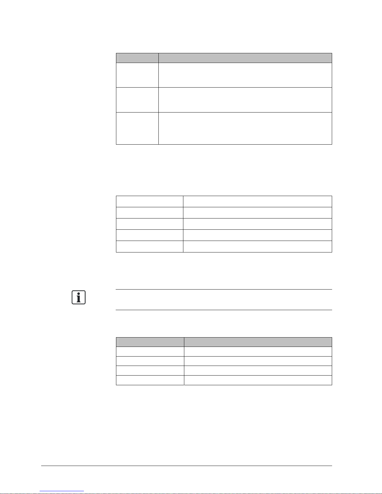
Signal word
The signal word classifies the danger as defined in the following table:
Signal word Danger level
DANGER DANGER identifies a dangerous situation, which will result
directly in death or serious injury if you do not avoid this
situation.
WARNING WARNING identifies a dangerous situation, which may
result in death or serious injury if you do not avoid this
situation.
CAUTION CAUTION identifies a dangerous situation, which could
result in slight to moderately serious injury if you do not
avoid this situation.
NOTICE
NOTICE
identifies possible damage to property that may
result from non-observance.
How risk of injury of presented
Information about the risk of injury is shown as follows:
WARNING
Nature and origin of the danger
Consequences if the danger occurs
Measures / prohibitions for danger avoidance
How possible damage to property is presented
Information about possible damage to property is shown as follows:
NOTICE
Nature and origin of the danger
Consequences if the danger occurs
Measures / prohibitions for danger avoidance
Page 11

Safety
11
Building Technologies 007025_i_en_--
Fire Safety & Security Products 07.05.2010
2.2 Safety regulations for the method of operation
National standards, regulations and legislation
Siemens products are developed and produced in compliance with the relevant
European and international safety standards. Should additional national or local
safety standards or legislation concerning the planning, assembly, installation,
operation or disposal of the product apply at the place of operation, then these
must also be taken into account together with the safety regulations in the product
documentation.
Electrical installations
WARNING
Electrical voltage
Electric shock
Work on electrical installations may only be carried out by qualified
electricians or by instructed persons working under the guidance and
supervision of a qualified electrician, in accordance with the electrotechnical
regulations.
Wherever possible disconnect products from the power supply when carrying
out commissioning, maintenance or repair work on them.
Lock volt-free areas to prevent them being switched back on again by mistake.
Label the connection terminals with external external voltage using a
'DANGER External voltage' sign.
Route mains connections to products separately and fuse them with their own,
clearly marked fuse.
Fit an easily accessible disconnecting device in accordance with IEC 60950-1
outside the installation.
Produce earthing as stated in local safety regulations.
Assembly, installation, commissioning and maintenance
If you require tools such as a ladder, these must be safe and must be intended
for the work in hand.
When starting the fire control panel ensure that unstable conditions cannot
arise.
Ensure that all points listed in the 'Testing the product operability' section below
are observed.
You may only set controls to normal function when the product operability has
been completely tested and the system has been handed over to the customer.
Page 12

Safety
12
Building Technologies 007025_i_en_--
Fire Safety & Security Products 07.05.2010
Testing the product operability
Prevent the remote transmission from triggering erroneously.
If testing building installations or activating devices from third-party companies,
you must collaborate with the people appointed.
The activation of fire control installations for test purposes must not cause
injury to anyone or damage to the building installations. The following
instructions must be observed:
‒ Use the correct potential for activation; this is generally the potential of the
building installation.
‒ Only check controls up to the interface (relay with blocking option).
‒ Make sure that only the controls to be tested are activated.
Inform people before testing the alarm devices and allow for possible panic
responses.
Inform people about any noise or mist which may be produced.
Before testing the remote transmission, inform the corresponding alarm and
fault signal receiving stations.
Modifications to the system layout and products
Modifications to the system and to individual products may lead to faults,
malfunctioning and safety risks. Written confirmation must be obtained from
Siemens and the corresponding safety bodies for modifications or additions.
Modules and spare parts
Components and spare parts must comply with the technical specifications
defined by Siemens. Only use products specified or recommended by
Siemens.
Only use fuses with the specified fuse characteristics.
Wrong battery types and improper battery changing lead to a risk of explosion.
Only use the same battery type or an equivalent battery type recommended by
Siemens.
Batteries must be disposed of in an environmentally friendly manner. Observe
national guidelines and regulations.
Disregard of the safety regulations
Before they are delivered, Siemens products are tested to ensure they function
correctly when used properly. Siemens disclaims all liability for damage or injuries
caused by the incorrect application of the instructions or the disregard of danger
warnings contained in the documentation. This applies in particular to the following
damage:
Personal injuries or damage to property caused by improper use and incorrect
application
Personal injuries or damage to property caused by disregarding safety
instructions in the documentation or on the product
Personal injury or damage to property caused by poor maintenance or lack of
maintenance
Page 13

Safety
13
Building Technologies 007025_i_en_--
Fire Safety & Security Products 07.05.2010
Disclaimer
We have checked that the content of this document matches the hardware and
software described. Despite this, we cannot rule out deviations and cannot
therefore assume liability for them matching completely. The details in this
document are checked regularly and any corrections needed included in
subsequent editions.
We are grateful for any suggestions for improvement.
2.3 Standards and directives complied with
A list of the standards and directives complied with is available from your Siemens
contact.
2.4 Release Notes
Limitations to the configuration or use of devices in a fire detection installation with
a particular firmware version are possible.
WARNING
Limited or non-existent fire detection
Personal injury and damage to property in the event of a fire.
Read the 'Release Notes' before you plan and/or configure a fire detection
installation.
Read the 'Release Notes' before you carry out a firmware update to a fire
detection installation.
NOTICE
Incorrect planning and/or configuration
Important standards and specifications are not satisfied.
Fire detection installation is not accepted for commissioning.
Additional expense resulting from necessary new planning and/or configuration.
Read the 'Release Notes' before you plan and/or configure a fire detection
installation.
Read the 'Release Notes' before you carry out a firmware update to a fire
detection installation.
Page 14

Setup and function
14
Building Technologies 007025_i_en_--
Fire Safety & Security Products 07.05.2010
3 Setup and function
3.1 Setup
The sounder base FDSB291 serves to provide an acoustic alarm in an addressed
fire detection system FS20.
The loud sound of the sounder base can be clearly heard as a danger signal when
a fire alarm sounds.
Eleven tones are programmed in the sounder base. Two tones can be activated for
different events (e.g. alarm and evacuation).
Features
Supply via detector line
The base sounder is activated via the connection for the external alarm
indicator
Communication with the control panel via the detector line
Compatible with all 'Sinteso' point detectors
Only functions when a point detector is inserted
Sounds are synchronized with all alarm sounders and sounder bases
FDSB291 on the same detector line (product version ≥30 and higher)
3.1.1 Details for ordering
Type Order no. Designation
FDSB291 A5Q00001647 Sounder base (FDnet) including two micro
terminals DBZ1190-AA
Page 15

Setup and function
15
Building Technologies 007025_i_en_--
Fire Safety & Security Products 07.05.2010
3.1.2 Product version ES
The product version ES provides the technical status of a device in terms of
software and hardware. The product version is provided as a two-digit number.
The details of your device's product version can be found:
On the packaging label
On the product label or the type plate
Product version on the packaging label
Details of the product version can be found directly on the packaging label in the
barcode:
ES
Example of a packaging label with details of the product version
Product version on the product label and the type plate
Details of the product version can be found after the device order number:
04
ES
Example of a product label with details of the product version
Depending on the product and various approvals, the product labels may differ in
terms of the information type and layout.
Look for your device's order number on the product label.
You will find the product version after the order number.
Page 16

Setup and function
16
Building Technologies 007025_i_en_--
Fire Safety & Security Products 07.05.2010
3.2 Function
3.2.1 Activation levels and sound intensity
The sounder base can be activated for two selectable event categories (e.g. prealarm or alarm). The tone and sound intensity can be configured individually for the
two selectable event categories. Eleven tones are available, each with two sound
intensities.
The base sounder is connected to the connection for the external alarm indicator. It
does not therefore take up an address on the detector line. The control panel
communicates with the point detector via the detector line. The point detector
communicates with the sounder base.
When testing the function with a detector exchanger and tester FDUD292 or an
intelligent detector tester FDUD293, a quiet test sound can be activated.
A function test is only possible if a point detector is inserted in the sounder base
FDSB291.
Base sounders with product version ≥30, which are operated on point detectors
with product version ≥30, are synchronized to alarm sounders (product version ≥30
and higher). Base sounders and alarm sounders must be connected to the same
detector line for this to happen.
As of point detectors and sounder bases with a product version ≥ 30, when
commissioning, the presence of the sounder base is detected automatically with
certain control panels, e.g. with the FS20.
3.2.2 Line separator
All FDnet devices are equipped with a line separator.
The FDnet device is equipped with electronic switches which isolate the defective
part in case of a short-circuit on the detector line. The rest of the detector line
remains serviceable. On a loop line all FDnet devices remain fully functional after a
simple error.
3.2.3 Interface to service devices
A proximity interface (MC link) is available for commissioning and maintenance in
order to communicate with the detector exchanger and tester FDUD292 and the
intelligent detector tester FDUD293.
For details, see Documents 007227 and 009718.
Page 17

Setup and function
17
Building Technologies 007025_i_en_--
Fire Safety & Security Products 07.05.2010
3.2.4 Diagnosis levels
The FDSB291 sounder base monitors its operation largely autonomously.
The following diagnosis levels are derived from the different control measurements:
Normal
Observe information
Fault
For details, see table below.
When a fatal error occurs, which impairs the proper function of the sounder base, a
fault message is signaled. To remedy the cause, additional information is available
in the sounder base. This can be displayed by the detector exchanger and tester
FDUD292 or the intelligent detector tester FDUD293, for example.
For details, see Documents 007227 and 009718.
Information displayed on the
detector exchanger and
tester
Meaning Measures
'no deviation' Normal, no fault is present
The sounder base is fully functional
None
'maybe excha.' 1 Observe information
Sounder base present, but parameters not
set
Set permissible parameters
Fault present
Invalid parameter settings (e.g. no sounder
base present)
Set valid parameters
Connect sounder base
Sounder base defective (Piezo monitoring) Replace sounder base
Any fault message
Short-circuit on sounder base connection Remedy short-circuit
The status 'Any fault message' can be displayed together with another status,
e.g. 'needed excha.' (replacement necessary).
1
The information displayed on the detector exchanger and tester is always in
English; no translation into the corresponding language.
Page 18

Setup and function
18
Building Technologies 007025_i_en_--
Fire Safety & Security Products 07.05.2010
3.2.5 Behaviour in degraded mode
Applicable for the FDnet:
If the main processor of the fire control panel fails, the control panel enters
degraded mode operation. Depending on the control panel, the fire control panel
may continue to provide the main alarming functions and signaling functions in
degraded mode operation.
Base sounders with a product version ES ≥ 30 which are operated on point
detectors with a product version ES ≥ 30 are also activated and deactivated in
degraded mode operation in the event of a fire alarm.
Degraded mode operation on the FDnet is not supported in the same way by all
control panels. The information in the 'List of compatibility' and in the corresponding
control panel documentation must be taken into account during project planning.
3.3 Accessories
3.3.1 Designation plate FDBZ291
To identify the location
Compatible with:
– Addressable detector base FDB221/FDB221-AA
– Flat, addressable detector base FDB222
– Detector base FDB271
– Sounder base FDSB29x
– Base attachment FDB291
Order no.: A5Q00002621
See also
Designation plate FDBZ291 [ 24]
3.3.2 Micro terminal DBZ1190-AA
Auxiliary terminal for connecting cables
For T-branches of additional cabling for detector
heating units, sounder base, external alarm
indicators, etc.
For wire diameters of 0.28 … 0.5 mm
2
4-pin
Order no.: BPZ:4677080001
Page 19

Setup and function
19
Building Technologies 007025_i_en_--
Fire Safety & Security Products 07.05.2010
3.3.3 Connection terminal DBZ1190-AB
Auxiliary terminal for connecting cables
For T-branches of additional cabling for cable
shielding, detector heating units, sounder base,
external alarm indicators, etc.
For wire diameters of 1 … 2.5 mm
2
3-pin
Order no.: BPZ:4942340001
3.3.4 Dummy detector FDX291
F
D
X
2
9
1
S
5
4
3
1
9
-
F
2
-
A
1
To protect the detector base from dirt
External labelling for identification
Does not open the contact in the detector base
Compatible with:
– Detector base FDB2xx
– Sounder base FDSB29x
Order no.: S54319-F2-A1
Page 20

Project planning
20
Building Technologies 007025_i_en_--
Fire Safety & Security Products 07.05.2010
4 Project planning
Please always take the country-specific provisions and the alarm organization for
project planning into account. In addition, the connection factors stated in the
specifications must also be taken into account.
See also
Technical data [ 30]
4.1 Compatibility
Compatible with control panels that support the FDnet detector line.
For details see 'List of compatibility'.
4.2 Range of application
Living rooms and lounges
Hotel rooms
Sick rooms
4.3 Restrictions
No direct interface to detector exchanger and tester FDUD292 and to intelligent
detector tester FDUD293. A function test of the sounder base FDSB291 with a
detector exchanger and tester FDUD292 or an intelligent detector tester
FDUD293 is only possible if a point detector is inserted in the sounder base
FDSB291. Communication between test device and sounder base is via the
point detector.
Not compatible with detector heating unit FDBH291
Cannot be synchronized with the alarm sounder FDS221 (only for product
version <30)
Cannot be installed in wet areas
Cannot be operated on a collective detector line
WARNING
Operating the sounder base on a collective detector line prevents alarms and
faults from being recorded and processed.
Fire may spread unhindered.
Do not use the sounder base FDSB291 on a collective detector line.
Page 21

Mounting / Installation
21
Building Technologies 007025_i_en_--
Fire Safety & Security Products 07.05.2010
5 Mounting / Installation
5.1 Assembly
The sounder base is fitted directly on the ceiling. The recess-mounted cable entry
or surface-mounted cable entry is as for a standard detector base.
1. Insert cables.
2. Use two screws to secure sounder base to ceiling.
− Ensure that the cables aren't pinched.
2
4
Ø max. 6 mm
2
1
3
Installing a sounder base
1 Recessed box 3 Screws
2 Sounder base 4 Designation plate
See also
Designation plate FDBZ291 [ 24]
Page 22

Mounting / Installation
22
Building Technologies 007025_i_en_--
Fire Safety & Security Products 07.05.2010
5.2 Electric connection
Note the positive and negative connections.
Only connect one wire per terminal. This is the only way of ensuring a problem-
free connection over the device's entire service life.
You will need at least one auxiliary terminal to connect the base sounder. Two
micro terminals DBZ1190-AA are included in the scope of supply for the
sounder base.
The external alarm indicator must always be connected using auxiliary
terminals.
Use unshielded cables if possible.
Select auxiliary terminals of the appropriate wire diameter.
Position the auxiliary terminals in the sounder base (see figure).
If using shielded cables:
‒ Connect the shielding of the detector line cables using an auxiliary terminal.
‒ Connect the shielding of the external alarm indicator cable with the positive
pole of the external alarm indicator connection.
‒ The shielding must not touch any external potentials.
For more information about using shielded cables, see document 007004.
Page 23

Mounting / Installation
23
Building Technologies 007025_i_en_--
Fire Safety & Security Products 07.05.2010
Procedure
1. Connect sounder base as shown in connection diagram.
2. Press the wires flat into the sounder base so they don't get pinched when
installing the point detector.
Connection diagram
+-+-+
-
-
+
FDSB29x
LINE
4
1
5
-
+
6
2
3
7
+
-
FDB2xx
+-+-+
-
4
5
89
Connection for sounder base
1 Control panel 6 Alarm indicator
2 Sounder base 7 Red
3 Detector base 8 Black
4 Connection terminals 9 Green
5 Micro terminals
See also
Micro terminal DBZ1190-AA [ 18]
Connection terminal DBZ1190-AB [ 19]
Page 24

Mounting / Installation
24
Building Technologies 007025_i_en_--
Fire Safety & Security Products 07.05.2010
5.3 Designation plate FDBZ291
1. Label designation plate FDBZ291 with location address of point detector or
alarm sounder.
2. Note the small mark on the installed point detector or alarm sounder and slide
designation plate into detector base or sounder base.
Installation of designation plate FDBZ291
1 Designation plate FDBZ291 3 Marks on point detector/alarm
sounder
2 Base attachment FDB291 4 Detector base/sounder base
See also
Designation plate FDBZ291 [ 18]
Page 25

Commissioning
25
Building Technologies 007025_i_en_--
Fire Safety & Security Products 07.05.2010
6 Commissioning
WARNING
Operating the sounder base on a collective detector line prevents alarms and
faults from being recorded and processed.
Fire may spread unhindered.
Do not use the sounder base FDSB291 on a collective detector line.
The device is commissioned via the control panel. The exact procedure is
described in the control panel documentation.
Conduct a performance check once commissioning is complete.
Page 26

Configuration
26
Building Technologies 007025_i_en_--
Fire Safety & Security Products 07.05.2010
7 Configuration
The following chapters contain the specifications of the different tones. The
specifications differ for sounder bases with product version <30 and product
version ≥30.
7.1 Sounder base with product version <30
Adjustable sound
intensity levels (typ.
values in [dBA/1 m] 1)
No. Tone Frequency
pattern
Sweep from
→ to
Pulse pattern
12 V 32 V
Norm
1 Continuous 970 Hz
85
79
90
83
'Evacuate'
BS 5839 Part 1
2 Intermittent 950 Hz 85
79
90
83
'Alert'
BS 5839 Part 1
3 Sweep-down 1200 Hz →
500 Hz
84
77
90
81
DIN tone
DIN 33404 Part 3
4 Slow-whoop
Sweep-up,
linear
500 Hz →
1200 Hz
85
78
90
82
NEN 2575
(Netherlands)
5 Pulse tone 500 Hz
79
72
85
77
Swedish Standard
SS 03 17 11, No. 1
'Imminent Danger'
6 Intermittent 500 Hz
78
70
83
75
Swedish Standard
SS 03 17 11, No. 3
'Important Message'
7 Continuous 500 Hz
81
74
86
78
Swedish Standard
SS 03 17 11, No. 4
'All clear'
Page 27

Configuration
27
Building Technologies 007025_i_en_--
Fire Safety & Security Products 07.05.2010
Adjustable sound
intensity levels (typ.
values in [dBA/1 m] 1)
No. Tone Frequency
pattern
Sweep from
→ to
Pulse pattern
12 V 32 V
Norm
8 Alternating 560 Hz
440 Hz
81
74
87
78
'French fire sound'
NF S 32-001 -1975
9 Intermittent 420 Hz
80
73
85
77
Australia 'Alert'
AS 2220 -1978
10 Slow-whoop
Sweep-up,
linear
500 Hz →
1200 Hz
85
78
90
82
Australia 'Action'
AS 2220 -1978
11 Intermittent 970 Hz
85
79
90
82
ISO 8201
US Temporal Tone LF
1
Details of sound intensity ±2 dBA
7.2 Sounder base with product version ≥30
Adjustable sound intensity
levels (typ. values in [dBA/1
m] 1)
No. Tone Frequency
pattern
Sweep from →
to
Pulse pattern
12 V 32 V
Norm
1 Continuous 970 Hz
85
79
90
83
'Evacuate'
BS 5839 Part 1
2 Intermittent 950 Hz
85
79
90
83
'Alert'
BS 5839 Part 1
3 Sweep-down 1200 Hz →
500 Hz
84
77
90
81
DIN tone
DIN 33404 Part 3
Page 28

Configuration
28
Building Technologies 007025_i_en_--
Fire Safety & Security Products 07.05.2010
Adjustable sound intensity
levels (typ. values in [dBA/1
m] 1)
No. Tone Frequency
pattern
Sweep from →
to
Pulse pattern
12 V 32 V
Norm
4 Slow-whoop
Sweep-up,
linear
500 Hz →
1200 Hz
85
78
90
82
NEN 2575
(Netherlands)
5 Pulse tone 500 Hz
79
72
85
77
Swedish Standard
SS 03 17 11, No. 1
'Imminent Danger'
6 Intermittent 500 Hz
78
70
83
75
Swedish Standard
SS 03 17 11, No. 6
'Local warning'
7 Continuous 500 Hz
81
74
86
78
Similar to
Swedish Standard
SS 03 17 11, No. 4
'All clear'
8 Alternating 560 Hz
440 Hz
81
74
87
78
'French fire sound'
NF S 32-001 -1975
9 Intermittent 420 Hz
80
73
85
77
Australia 'Alert'
AS 2220 -1978
10 Slow-whoop
Sweep-up,
linear
500 Hz →
1200 Hz
3.75 s
0.25 s
85
78
90
82
Australia 'Action'
AS 2220 -1978
11 Intermittent 970 Hz
85
79
90
82
ISO 8201
US Temporal Tone LF
1
Details of sound intensity ±2 dBA
Page 29

Maintenance / Repair
29
Building Technologies 007025_i_en_--
Fire Safety & Security Products 07.05.2010
8 Maintenance / Repair
8.1 Status retrieval
The FDSB291 sounder base has a proximity interface (MC link).
Using this interface, it is possible to read out data from the device in a proximity
method over short distances with the detector exchanger and tester FDUD292 or
the intelligent detector tester FDUD293.
For details, see Documents 007227 and 009718.
The following actions can be performed from the control panel:
Configure sounds
Commissioning
Activate / deactivate sound
Read error list / status register
8.2 Function check
The devices are automatically subjected to a performance check during the selftest. Nevertheless, it is necessary to check the devices on site at regular intervals.
Recommendation:
Check the devices every year.
Replace heavily soiled or damaged devices.
No other special maintenance work is necessary.
More information can be found in the control panel documentation.
Page 30

Specifications
30
Building Technologies 007025_i_en_--
Fire Safety & Security Products 07.05.2010
9 Specifications
9.1 Technical data
Operating voltage 12 … 33 VDC Detector line
Operating current:
Quiescent condition
Sound activated
150 μA
1.2 mA
Maximum current connection factor 5
Quiescent current connection factor 0,5
Address connection factor 0
Separator connector factor 0
Protocol FDnet
Compatibility See 'List of compatibility'
Number of external alarm indicators that
can be connected
1 External alarm indicators
Specifications See document 007004
Number of sounds 11 Base sounder
Activation levels 2
Sound level Depending on the set tone; see chapter
'Configuration' for details
Communication protocol EAI link, only with detectors and sounder bases
with product version ≥30 and with automatic
detection
Detector line and external alarm
indicator:
Design
Spring clips
Connections
Cable cross section 0.2 … 1.5 mm²
Operating temperature -25 … +70 °C Ambient conditions
Storage temperature -30 … +75 °C
Air humidity ≤95 % rel.
Protection category according to
EN 60529/IEC 60529
IP43
Electromagnetic compatibility:
1 MHz … 1 GHz
1 GHz … 2 GHz
50 V/m
30 V/m
Dimensions (W x H x D) 153 x 27 x 93 mm Mechanical data
Housing material ABS
Colour ~RAL 9010 pure white
Page 31

Specifications
31
Building Technologies 007025_i_en_--
Fire Safety & Security Products 07.05.2010
Standards EN 54-3 Standards
VdS approvals G204062
Certificates 0786-CPD-20013
CE conformity mark Yes
Protection categories IEC 60529
QA Standards
Siemens Standard SN 36350
ISO 9001
ISO 9004
9.2 Dimensions
153 mm
27 mm93 mm
Sounder base dimensions
9.3 Environmental compatibility
Reusable materials
Electronic parts and synthetic materials can be easily separated
Halogen-free synthetic materials, marked by embossed code
The synthetic materials used do not generate any toxic substances during
combustion.
The larger plastic parts are labeled according to ISO 11469. The basic polymer
abbreviations comply with ISO 1043. The materials can be separated and recycled
on this basis.
Page 32

Annex technical data
32
Building Technologies 007025_i_en_--
Fire Safety & Security Products 07.05.2010
10 Annex technical data
10.1 Tones and sound intensities of the alarm sounder (32 VDC)
Sound intensity measured in dBA/1 m with -0/+4 dBA (32 VDC)
Tone No. 1: Continuous
Sound
intensity
Horizontal Vertical
15° 45° 75° 105° 135° 165° 15° 45° 75° 105° 135° 165°
0 (max.) 79 80 83 84 81 79 80 80 83 85 80 82
1 (low) 70 72 75 75 73 70 72 70 75 76 71 73
Tone No. 2: Intermittent
Sound
intensity
Horizontal Vertical
15° 45° 75° 105° 135° 165° 15° 45° 75° 105° 135° 165°
0 (max.) 78 80 84 84 82 78 81 80 83 84 80 82
1 (low) 70 72 77 77 74 70 73 72 76 77 72 75
Tone No. 3: Sweep-down
Sound
intensity
Horizontal Vertical
15° 45° 75° 105° 135° 165° 15° 45° 75° 105° 135° 165°
0 (max.) 80 81 85 85 81 80 81 82 85 86 77 82
1 (low) 70 72 75 74 72 69 72 72 75 76 71 73
Tone No. 4: Slow-whoop Sweep-up, linear
Sound
intensity
Horizontal Vertical
15° 45° 75° 105° 135° 165° 15° 45° 75° 105° 135° 165°
0 (max.) 79 82 86 86 80 76 83 81 85 86 82 83
1 (low) 70 71 76 76 71 67 72 72 76 76 72 74
Page 33

Annex technical data
33
Building Technologies 007025_i_en_--
Fire Safety & Security Products 07.05.2010
Tone No. 5: Pulse tone
Sound
intensity
Horizontal Vertical
15° 45° 75° 105° 135° 165° 15° 45° 75° 105° 135° 165°
0 (max.) 75 75 80 80 74 72 77 77 80 80 77 79
1 (low) 66 66 70 70 65 64 68 68 70 71 68 68
Tone No. 6: Intermittent
Sound
intensity
Horizontal Vertical
15° 45° 75° 105° 135° 165° 15° 45° 75° 105° 135° 165°
0 (max.) 75 75 79 79 74 71 77 77 79 79 76 76
1 (low) 65 65 69 70 64 64 68 68 70 70 67 67
Tone No. 7: Continuous
Sound
intensity
Horizontal Vertical
15° 45° 75° 105° 135° 165° 15° 45° 75° 105° 135° 165°
0 (max.) 77 77 80 81 75 74 79 79 80 81 78 78
1 (low) 67 67 76 72 66 64 69 69 71 72 69 69
Tone No. 8: Alternating
Sound
intensity
Horizontal Vertical
15° 45° 75° 105° 135° 165° 15° 45° 75° 105° 135° 165°
0 (max.) 75 77 81 82 75 72 68 68 81 81 77 77
1 (low) 66 68 72 73 66 64 69 69 72 72 68 68
Tone No. 9: Intermittent
Sound
intensity
Horizontal Vertical
15° 45° 75° 105° 135° 165° 15° 45° 75° 105° 135° 165°
0 (max.) 75 76 79 80 75 72 78 78 80 80 78 78
1 (low) 65 66 70 70 66 64 68 69 70 70 69 69
Page 34

Annex technical data
34
Building Technologies 007025_i_en_--
Fire Safety & Security Products 07.05.2010
Tone No. 10: Slow-whoop Sweep-up, linear
Sound
intensity
Horizontal Vertical
15° 45° 75° 105° 135° 165° 15° 45° 75° 105° 135° 165°
0 (max.) 79 80 84 85 79 76 81 81 84 84 81 81
1 (low) 70 71 71 76 71 67 72 72 76 76 72 72
Tone No. 11: Intermittent
Sound
intensity
Horizontal Vertical
15° 45° 75° 105° 135° 165° 15° 45° 75° 105° 135° 165°
0 (max.) 76 80 84 85 79 76 80 81 85 85 81 80
1 (low) 67 71 75 76 70 66 71 72 76 76 72 72
Page 35

Index
35
Building Technologies 007025_i_en_--
Fire Safety & Security Products 07.05.2010
11 Index
B
Base sounder
Connection, 22
C
Cable entry, 21
Collective detector line, 20
Compatibility, 20
Collective detector line, 20
Detector, 14
Detector exchanger and tester FDUD292, 20
Detector heating unit FDBH291, 20
Intelligent detector tester FDUD293, 20
Compatibility with control panels, 20
Control panel, 25
D
Degraded mode operation
Failure of fire control panel, 18
Detector exchanger and tester FDUD292, 17
MC link, 16, 29
Detector exchanger and tester FDUD29x, 20
Detector heating unit FDBH291
Compatibility, 20
E
ES
Product version, 15
F
Failure of fire control panel
Degraded mode operation, 18
Function test
Test sound, 16
I
Intelligent detector tester FDUD293, 17, 20
MC link, 16, 29
Interface
MC link, 29
L
Line separator
Function, 16
List of compatibility, 7, 18, 20
M
Maintenance intervals, 29
MC link, 29
Detector exchanger and tester FDUD292, 16, 29
Intelligent detector tester FDUD293, 16, 29
Proximity interface, 16
P
Packaging label
Product version, 15
Product label
Product version, 15
Proximity interface
MC link, 16
S
Short-circuit
Line separator, 16
Supply, 14
T
Type plate
Product version, 15
W
Wet area, 20
Page 36

Issued by
Siemens Switzerland Ltd
Industry Sector
Building Technologies Division
International Headquarters
Gubelstrasse 22
CH-6301 Zug
Tel. +41 41-724 24 24
www.siemens.com/buildingtechnologies
© 2004-2010 Copyright Siemens Industry, Inc.
Technical specifications and availability subject to change without notice.
Document ID 007025_i_en_-- Manual FD20
Edition 07.05.2010 Register 6
 Loading...