

Page 1

Induction Motors/
Generators
Installation
Operation
Maintenance
Large Frame Vertical
680, 800, 1120 Frames
Types CGV, CGHS, CGIIV, CGIIHS, CGGV, CGGHS, CAZV, CAZHS, CAZBV, CAZBHS
ANIM-03535-0814
(Supercedes all previous issues of ANIM-03535)
©2014 Siemens Industry, Inc. All rights reserved.
Page 2

Table of Contents
Page
Page
TABLE OF CONTENTS
1
OPERATION
11
SAFETY PROCEDURES
2
Initial Start
11
INTRODUCTION
3
Out of Service/Storage
11
Warranty
3
Normal Operation
12
Receiving
3
Trouble Shooting
13
Handling
4
MAINTENANCE
15
Temporary Storage
4
Preventive Maintenance
15
Description
4
Inspection
15
Type Designations
4
Corrective Maintenance
16
INSTALLATION
5
Rotor Cleaning
17
Location
5
Stator Cleaning
17
Foundation
5
Insulation Resistance
17
Mounting
5
Drying Insulation
17
External Wiring
6
Bearings
18
Changing Direction of Rotation
7
Bearing Replacement
20
Vibration
7
Kingsbury-type Bearin gs
22
System Frequency (Resonance)
7
Shaft or Flange Face Runout
27
Alignment
7
SPARE PARTS
28
Shimming Technique
8
Identification
28
Tests Before Operation
9
Vertical Solid & Hollow Shaft Nomenclature
34
Typical Motor Control Settings
10
MOTOR SERVICE RECORD
35
Note - Thes e instructions do not purport t o cover all details or variations in equipment, nor to prov ide for every
possible contingency to be met in connection with installation, operation or maintenance. Should further
information be desired or should particular problems arise which are not covered sufficiently for the user’s
purposes, the matter should be referred to;
1. Your local Siemens Sales Office.
--Or--
2. Siemens Technical Support Communication Center:
Inside the U.S.: 1-800-333-7421
Outside the U.S.: +1 423-262-5710
Online: www.industry.usa.siemens.com/industry and click on Industry Services
The contents of this instruction manual shall not become part of or modify any prior or existing agreement,
commitment or relationship. The sales contract contains the entire obligation of Siemens. The warranty
contained in the contract b etween the parties is th e sole warranty of Siem ens. Any statements cont ained herein
do not create new warranties or modify the existing warranty.
Siemens machines are built in accordance with the latest applicable revision of the National Electric Code,
Underwriters Laborator ies Standards and Proce dures, and NEMA (Nati onal Elect rical Manuf acturers Associatio n)
Standards. These p ublications and this instruction manual should be thoroughly rea d and understood prior to
beginning any work on this equipment.
The information contained within is int ended to as sist operat ing pers onnel b y providin g infor m ation on the genera l
characteristics of the pur chased equipment. It does not relieve th e user of the responsibility of using acc epted
engineering practices in the installation, operation and maintenance of this equipment.
Should a conflict arise between the general information in this manual and the contents of the drawings and
supplementary material, the latter shall take precedence.
The illustrations in this book show typical machines. Special features deviate from those pictured.
- 1 -
Page 3
Safety Procedures
DANGER
this equipment.
the machine will be referred to as a “motor”.
This equipment contains hazardous voltages. Death,
serious personal injur y or property damage c an result
if safety instructions are not followed.
The successful and safe operation of motors and
generators is dependent upon proper handling,
installation, operation and maintenance, as well as
upon proper design and manufacture. Failure to
follow certain fundamental installation and
maintenance requirements may lead to persona l inj ury
and the failure and loss of the motor as well as
damage to other property.
Only qualified personnel should work on or around
this equipment after becoming t horoughl y fam iliar with
all warnings, safety notices and maintenance
procedures contained herein. Only qualified
personnel should be involved in the inspection,
maintenance and repair pr ocedure a nd all plant saf ety
procedures must be observed.
Qualified Person: For the purpose of this manual
and product labels, a Qualified per son is one who is
familiar with the installation, construction and
operation of the equ ipment, an d the hazards involved.
In addition, he or she has the following qualifications:
a. Is trained and authorized to energize, de-energize,
clear, ground and tag circuits and equipment in
accordance with established safety practices.
b. Is tra ined in the proper care and us e of protective
equipment, such as rubber gloves, hard hat,
safety glasses, fac e shields , flash cloth ing, etc., in
accordance with established safety practices.
c. Is trained in rendering first aid.
Danger: For the pur pose of this manual and product
labels, Danger indicates an imminently hazardous
situation which, if not avoided, will result in death or
serious injury.
Warning: For the purpose of this manual and product
labels, Warning indicates a potentially hazardous
situation which, if not avoided, may result in minor or
moderate injury.
Caution: For the purpose of this manual and prod uct
labels, Caution indicates a potentially hazardous
situation which, if not avoided, may result in minor or
moderate injury. It is also used to alert a gains t unsaf e
practices.
Motors should be installe d and gro und ed per l ocal an d
national codes.
Do not operate this equipment in excess of the va lues
given on nameplate or contrary to the instructions
contained in this manual. The equipment (or a
prototype) has been factory tested and found
satisfactory for the condition for which it was sold.
Operating in excess of these conditions can cause
stresses and strains beyond design limitations.
Failure to heed this war ning may result in equipment
damage and possible personal injury.
Hazardous voltage.
Will cause death, serious injury,
electrocution or property damage.
Disconnect all power before working on
NOTE
Squirrel cage induction machines can be driven by
various types of prime movers. These will act as induction
generators. This instruction manual applies to both motors
and induction generators. However, for clarity reasons,
- 2 -
Page 4

DANGER
equipment.
Introduction
Hazardous voltage.
Will cause death, serious injury, electrocution
or property damage.
Disconnect all power before working on this
These instructions present general recommendations for
installation, operation and maintenance of induction motors
built at the Norwood plant. If additional information is
required, contact Siemens Energy & Automation.
Warranty
See your sales contract for warranty coverage.
Documentation of storage maintenance, alignment
and regreasing may be required for certain warranty
considerations.
Receiving
Motors are shipped in first class condition. They have been
inspected and are skidded to prevent damage from ordinary
handling during shipment.
Inspect new motors for shipping invoice. Make the
examination before removing from cars or trucks. If damage
or indication of rough handling is evident, file a claim with
the carrier at once, and notify your Siemens sales
representative.
Remove only the shipping invoice. Do not remove tags
pertaining to lubrication, operation and storage instructions.
Read and follow all instructions to insure that no damage to
motor bearings, (due to condensation) and motor windings
occurs during storage.
Use care in handling. Dropping the motor or otherwise
imposing shock loads can cause unseen and undetected
damage to bearings. This damage such as false brinelling
of the races of anti-friction bearings can result in early
bearing failure.
If supplied, energize space heaters to help prevent
condensation within the motor enclosur e.
Motors having oil lubricated bearings are shipped WITHOUT
OIL in the bearing reservoir. These bearings and journal
surfaces are protected during shipment by a TEMPORARY
film of rust inhibiting oil.
Immediately upon receiving a unit with oil lubricated
bearings:
1. Check for moisture accumulation. Remove any traces
of oxidation before putting the motor in service.
2. Fill bearing reservoirs to normal level with a nonfoaming, non-detergent turbine oil (See Maintenance
Section).
3. Rotate the shaft several turns, by hand, to distribute the
oil over bearing parts.
- 3 -
Page 5

WARNING
and spreaders.
NOTE
information.
Totally-Enclosed Water-to-Air
Cooled
Totally-Enclosed Air-to-Air
Cooled with shaft-mounted fan
Totally-Enclosed Air-to-Air
Cooled using auxiliary blower
Introduction
Heavy equipment.
Improper handling may cause death, serious injury or property
damage.
Check lifting devices before lifting. Use proper slings, chains
Note any warning plates on motor and follow instructions on
each plate.
Handling
Lifting devices are provided for handling only. An
experienced rigger should be used to install motors.
To avoid damage, the use of spreader bars is recommended
on other than single point lifts. Lifting devices are provided to
facilitate handling with shackles and cables. Avoid pounding
or bumping shaft, coupling or bearing parts, as shocks may
damage bearings.
NOTE WEIGHT BEFORE LIFTING. The weight is indicated
on the outline drawing. Apply tension gradually to cables.
Do not jerk or attempt to move the unit suddenly.
Temporary Storage
If the equipment is not to be installed and operated soon after
arrival, store it in a clean, dry, well- ventilated place, free from
vibration and rapid or wide variations in temperature. Rotate
the shaft a minimum of 10 complete turns by hand each
month to coat the bearings with lubricant which will retard
oxidation or corrosion, and prevent possible false brinelling.
If drain plugs are provided in enclosed motors, they must be
removed periodically to drain any water accumulation from
the motor. Consider a unit in storage when:
1. It has been delivered to the job site and is awaiting
installation.
2. It has been installed but operation is delayed over 30
days pending completion of plant construction.
3. There are long (30 day) periods between operating
cycles.
4. The plant (or department) is shut down for 30 days.
Energize space heaters, if supplied.
5.
Description
"P" flanged, vertical type units above NEMA frames
680/800/1120 are the subjects of this manual. The
instructions include high thrust, oil lubricated spherical roller
or Kingsbury-type bearings.
Check rating plate for your particular type construction.
Type Designations
The motor type designation consists of a basic letter or
letters indicating the motor enclosure type to which other
letters may be added denoting modifications.
Motor Type Motor Enclosure
CGV, CGHS
CGIIV, CGIIHS Weather Protected Type II
CGGV, CGGHS
CAZV, CAZHS
CAZBV, CAZBHS
Open Drip Proof or Weather
Protected Type I
Storage requirements vary, depending on the length of
storage and the climate. For storage periods of thirty (30)
days or longer or climate variations, consult Siemens
Storage Recommendations ANIM-03114. Storage
maintenance is to be documented for warranty
- 4 -
Page 6

Installation
NOTE
regulations, including OSHA.
and the foundation.
NOTE
the motor.
NOTE
accumulate and drain into motor connection box.
Mounting
The information contained in this book is intended to
assist operating personnel by providing information on
the general characteristics of the purchased equipment.
IT DOES NOT relieve the user of the responsibility of
using accepted engineering practices in the installation,
operation and maintenance of this equipment , and
complying with Federal, State and local rules and
Location
Select a location for the motor and driven unit that will:
1. Be clean, dry, well ventilated, properly drained, and
provide accessibilit y for inspection, lubrication and
maintenance. Outdoor installations may require
protection from the elements.
2. Provide adequate space f or motor removal witho ut
shifting the driven unit.
3. Permit the motor to saf ely deliver ad equate power .
Temperature rise of a s tandard motor is based on
operation at an altitude not higher than 3,300 feet
above sea level.
4. Avoid condensation of m oisture in bear ings and on
windings. Motors should not be s tore d or oper ated
in areas subject to rapid temperature changes
unless motors are energized or protected with
space heaters.
Foundation
Concrete (reinforced as required) makes the best
foundation, particularly for large motors and driven
units. In sufficient mass it provides rigid support that
minimizes deflection a nd vibration. It may be located
on soil, structural stee l, or building floors provided t he
total weight (motor, driven unit, foundation) does not
exceed the allowable bearing load of the support.
Allowable bearing loads of structural steel and floors
can be obtained from engineering handbooks. Building
codes of local communities give the recommended
allowable bearing loads f or different types of soil. For
rough calculation the foundation should be
approximately 2-1/2 times total unit weight.
NOTE
If normal vibration or noise will be objectionable (as in
office buildings), it may be advisable to use vibration
dampeners between the machine or driven/drive unit,
Mount the machine securely and align accur ately with
the driven equipment.
1. Direct mounted to dr iven/drive equi pment: the two
units must be firmly secured and the driven
equipment placed on an adequate foundation.
2. Floor plate mounted equ ipment must be very rigid
and free from vibration.
Any excessive vibration of either method will cause
loss of alignment, premature bearing wear and
eventual breakdown.
If motor is driving a pump and the back pressure is
maintained after shut-down, protect the motor with quickacting check values or non-reverse mechanism within
Flange Mounting
Solid Shaft Motors
To m ount round fram e motor to driven unit proc eed as
follows:
Round frame motors can be rotated within flange
mounting bolt spacing to gain a satisfactory position for
grease fittings and conduit attachments, and to mate
run-out differences to avoid shimming flange fits.
Terminal boxes without accessory devices can be turned
to four equally spaced positions for access to conduit
system; arrange the system so that water will not
1. Use a hoist; rig a sling around the lifting lugs.
2. Position motor (per note a bove) and move toward
driven unit - engaging cleaned flanged surfaces.
3. Insert flange mounting bolts and tighten to snug
tight.
4. Secure attachments bet ween motor and shaft and
load. (i.e. set screws tightened against shaft key.)
5. Turn shaft by hand; check for f r ee rotation; b in din g;
scraping; sticking.
6. Tighten all flange bolts. (Avoid warping or
springing the flange.)
7. Turn shaft again to check for free rotation.
- 5 -
Page 7

NOTE
allow coupling to operate.
Eliminate upthrust before operating.
stating or storing motor.
DANGER
this equipment.
NOTE
Section.
wrong direction of rotation.
Installation
Hollow Shaft Motors
The motor should be set on its base first, and the
driven shaft inserted through the hollow shaft. There
are times, however, when these motors are lifted an d
lowered over the driven shaft. In either case, do not
cause damage to the shaf t by bending or scrapin g the
threads.
Proceed as follows:
External Wiring
Hazardous voltage.
Will cause death, serious injury,
electrocution or property damage.
Disconnect all power before working on
1. Remove coupling cover and raise motor with sling
and hoist.
2. Slowly lower motor; carefully engage stud ( if
used) and rabbet. (Position motor to allow access
for power connection and lubrication.) Install
flange nuts (bolts, if used) and snug.
3. Insert pump drive shaft into hollow shaft; arrange
coupling and driven shaft in line with Gib Key Slot.
4. Insert Gib Key, connect driven shaft to coupling
and adjust pump nut for proper impeller clearance.
(Remove Locking Bar if provided.)
5. Turn shaft by hand to check for free rotation and
shaft alignment. There must be no binding,
scraping, or sticking.
6. If used, check the operation of the non-reverse
device: also check action of self-release coupling,
if that type of coupling is used (see Figure 12).
A self-release coupling is shipped with three bolts
holding it in place. These bolts must be removed to
7. After alignment, uniformly and securely tighten all
flange nuts (bolts).
8. Turn shaft by hand again; check for free rotation.
9. Replace coupling cover.
CAUTION
Continuous upthrust may damage motors.
CAUTION
Improper lubrication can cause damage to bearings.
Check oil reservoir for proper oil grade and level before
Before running motor, see Initial Start in Operation
CAUTION
FOR MOTORS EQUIPPED WITH BACKSTOP OR
NON-REVERSE DEVICE
Attempting to rotate motor with non-reverse device
in wrong direction may result in severe damage to
the motor.
Connect power supply phases to motor terminals exactly
as indicated on motor nameplate to insure proper
direction of rotation. Any other connection will result in
Starting and overload c o ntr ol dev ic es must be matched
to motor rating. For safety or convenience they may
need to be installed some distance from the motor.
Follow the control m anufacturer’s instructions to m ake
proper installations and connections. Observe the
following:
1. Connect electrical power supply to conform to
National Electric Code and any local regulations.
Line voltage and wire capacity must match motor
rating stamped on the nameplate.
2. With the driven equipment disconnected,
momentarily energize the motor to check rotation.
3. If motor is three-phase type, reverse rotation (if
required) by interchanging any two of the three
power leads.
- 6 -
Page 8
or change fans.
rotation is changed, the ratchets must be changed.
Speed,
RPM
Rotational
Frequency/Hz
Velocity,in/s Peak
(mm/s)
3600
60
0.15 (3.8)
1800
30
0.15 (3.8)
1200
20
0.15 (3.8)
900
15
0.12 (3.0)
720
12
0.12 (3.0)
600
10
0.12 (3.0)
Installation
Changing Direction of Rota t ion
Look for rotation plates usually mounted on opposite
drive end of the motor.
CAUTION
Excessive heat.
Motor may overheat if motor cooling fans run in the
wrong direction. Run mot or in direction shown on motor
NOTE
If open or enclosed units have non-reverse ratchet s and
The internal rotor fan direction must be considered if
changing direction of rotation.
To reverse rotation – consult factory.
Vibration
After flange mounting b olts hav e be en t ig hten ed, c h eck
end play. Run the un it at a minimum load and check
vibration.
The standard unfilter ed vibratio n limits per NEMA MG 1
for a resiliently mounted motor are:
If vibration is excess ive, loosen flange m ounting bolts
and shift within mounting flange clearance. If this
shifting does not reduce vibration to acceptable limit,
and unit is coupled to load, check shaft alignment and
system reed frequency.
System Frequency (Resonance)
To achieve reasonable vibration levels when a motor,
pump, and support are operating together, the
responsibility is with the system designer.
If the probable vibration c haracteristic s of a s ystem are
calculated before construction begins proper design
can often reduce trouble before it becomes a costly
reality. The effec t of most pum p heads beca use of th e
access openings for coupling, bearing, and pump
adjustments, will lower the system reed frequency.
Generally, the reed frequency of the unit alone
mounted on an infinite mass is at least 15% above or
below the unit operating speed. If the system reed
frequency is at or near operating speed, a decision
must be made to raise or lower the system reed
frequency by altering the rigidity of the motor-support
structure.
Alignment
Accurate shaft alignment between motor and driven
equipment is essential. Improper alignment may result
in vibration, bearing overloads and excessive shaft
stresses. Flexible couplings will not compensate for
excessive misalignment.
Alignment Procedure (Solid Shaft)
The following checking procedure applies to a unit
consisting of motor/generator, coupling, and a
driven/drive component. Although applicable to most
types of couplings, it is primarily intended for the
rabbet-fit type. For oth er types, where the procedures
differ, refer to the coupling manufacturer's Installation
and Maintenance Instructions.
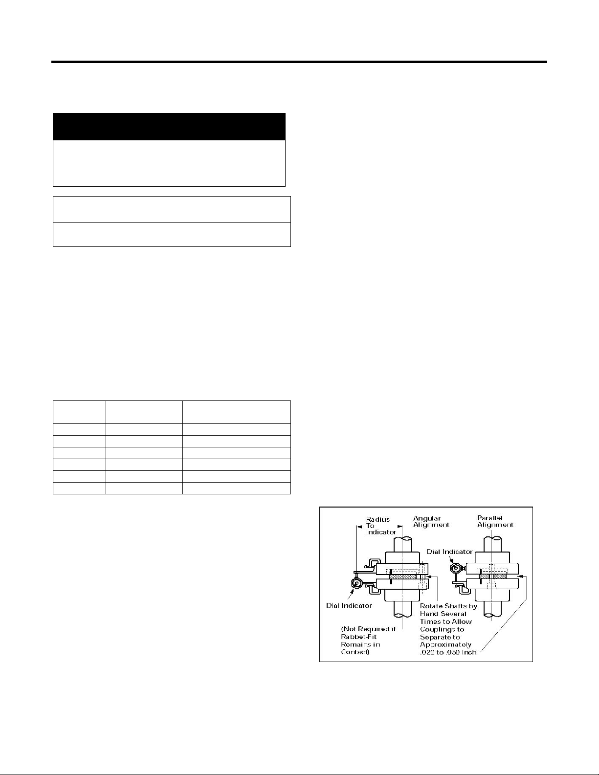
Work in one plane at a time and test for parallel or
angular alignment with a dial indicator mounted as
shown in Figure 1. Proceed as follows:
1. Set indicator dial to zero, at starting point.
2. Slowly turn both coupling halves a complete turn.
3. Observe dial reading at 90 degre e increm ents f rom
starting point.
4. Acceptable parallel alignment occurs when the
total indicator readings do not exceed 0.002
inches.
5. Acceptable angular alignment occurs when the
total indicator readin gs do not exceed 0.002 in./ft.
radius to dial indicator.
Figure 1
- 7 -
Page 9

operating.
Figure 2
Installation
Alignment Procedure (Hollow Shaft)
Hollow shaft units require accurate alignment with
respect to the unit shaf t an d the driven/drive equipment
shaft. The pump s haft acts as a pendulum supported
by the top coupling and unit bearing.
Align the unit as follows:
1. Clamp dial indicator to pum p s haf t, alig n with bas ebolt plane and set dial indicator to zero (Figure 2).
2. Remove top cover and rot ate both unit and pump
shafts.
3. Read dial indicator at 90 degree increments from
starting point.
4. Acceptable alignment occurs when indicator
readings do not exceed 0.0005 inches.
5. Shim flange faces if necessary (Figure 3).
When alignment and v ibration of unit are within lim its,
engage drive. Run un it at m inimum load and ch eck for
vibration - continue to increase load and checking
vibration until full load is obtained.
Shimming Technique
To avoid the possibility of twisting the flange when
shimming between the f langes, minor s hims should be
one-half the thickness of the major shim. Shims
should not penetrate deeper than the bolt hole circle
and not be wider than twice the penetration distance
(Figure 3).
CAUTION
Excessive vibration may cause damage to bearings
or other motor components.
Determine and correct cause(s) of vibration before
Figure 3
- 8 -
Page 10
Installation
DANGER
with manufacturer’s instructions.
Test only in accordance with IEEE Std. 43.
NOTE
Devices" - IEEE Publication No. 119.)
5.234)5.234( −+= t
r
R
T
5.234)255.234(
50.0
61.0
−+=T
82=T
Tests Before Operation
Insulation Resistance
Check insulation resistance prior to connecting motor
to power supply. A hand cranked or solid state
electronic insulation resistance tester, at least 500 volts
d.c., but not over rated voltage, is usually used (see
Maintenance).
See IEEE Recommended Practice for Testing
Insulation Resistance Rota t ing Mach inery IEEE Std 43.
Dielectric (Hi-Pot) Tests
All motors receive a factory dielectric test in
accordance with ANSI and IEEE Standar ds.
Dielectric testing may result in
personal injury or death.
Operate dielectric test equipment only
with qualified personnel, in acc ordance
If a dielectric test is made on an old or repaired
winding, to evaluate service reliability, the test voltage
applied may vary from the rated terminal voltage to
some higher value. The factory should be consulted
when establishing the tes
old or repaired equipment.
t voltage and procedure for testing
If normal vibration or noise will be objectionable (as in
Instruments that operate on the principle of the Kelvin
Bridge are preferred. (See "Temperature Measuring
The cold resistance, or the resistance at normal room
temperature, must be measured after the machine has
been idle for some time, usually before starting, or cold
resistance value may be obtained from the factory.
The cold temperature of the coils should be measured
because coil temperature may not be the same as the
surrounding air.
The average temperature of the winding is obtained by
taking resistance measurements, at the motor load
terminals and using the following equation:
Where T = hot temperature in degrees C
R = hot resistance
r = cold resistance at temperature t
t = cold temperature of winding in deg C (amb)
As an example, assume the cold resistance of 0.50
ohms at 25°C, and the hot resistance (taken
immediately after motor is de-energized, and has
stopped rotating) is 0.61 ohms, then:
CAUTION
Excessive dielectric testing may cause damage to
insulation.
Winding Resistance (Temperature)
The change in resistance of a winding provides an
accurate measure of the average temperature of a
winding, and is generally used to determine the
temperature of the stator windings. The
measurements must be made carefully with
instruments known to be accurate, and preferably with
the same instruments for both hot and cold
measurements.
The temperature measured by imbedded detectors or
by the change in resistance is generally higher than
thermometer measurements and is closer to the true
hottest spot temperature in the machine. For this
reason, the Standards permit higher observable
temperatures when measurements are taken in this
manner.
- 9 -
Page 11

Installation
Trip
(Shutdown)
Timer Trip
Setting
Winding Temperature
• Class F Insulation
155°C
170°C
(Thermocouple or RTD’s)
Sleeve Bearing
90°C
95°C
Antifriction Bearing
100°C
105°C
4 Amps
(2)
Circuit
8 Amps
(2)
Circuit
0.2 sec.
(2)
Instantaneous Overcurrent
• With ½ Cycle Delay
1.8 times Locked Rotor Amps
(2)
• Without Time Delay
2.4 times Locked Rotor Amps
(2)
Maximum Voltage
110 % of Rated Voltage
10 sec.
Minimum Voltage
specified)
(3)
(3)
Suggested Vibration Limits
RPM
3600
1800
1200
900 and
Slower
Shaft (mils, pk-to-pk) – Alarm
(4)
2.8
3.2
3.8
4.5
Shaft (mils, pk-to-pk) – Trip
(4)
3.3
3.7
4.3
5.0
Housing (in./sec.) - Trip
0.25
0.25
0.25
0.25
Typical Motor Control Settings
• Class B Insulation
Motor Bearing Temperature
•
•
Ground Fault
(the minimum voltage
also applies to starting unless otherwise
Alarm
130°C
Primary
155°C
Primary
90 % of Rated Voltage 10 sec.
(1)
Maximum Frequency D ev i ati on ±5% 10 sec.
Maximum of Voltage Plus Frequency Deviation ±10% 10 sec.
Maximum Voltage Unbalance
Maximum Current Unbalance
(1)
Maximum time at maximum condition before control device is to operate.
(2)
Increase as necessary to avoid nuisance trips.
(3)
This is the maximum deviation from the average of the three phases.
(4)
Applies only when vibration probes are supplied.
1% 15 sec.
8% 15 sec.
- 10 -
Page 12

Operation
WARNING
instructions in this manual.
rotor cage to cool.
wrong direction of rotation.
WARNING
compressed air.
NOTE
Service
Initial Start
Improper operation may cause personal injury or
damage to equipment.
Operate within nameplate ratings and in accordance with
CAUTION
Do not exceed number of Siemens specified hot and
cold starts per hour.
Will cause overheating.
Allow time between starts to permit stator windin gs and
If motor has been out of service or in storage for more
than 30 days, consult Siemens Storage
Recommendations ANIM-03114, Preparation for
CAUTION
FOR MOTORS EQUIPPED WITH BACKSTOP OR NONREVERSE DEVICE
Attempting to rotate motor with non-reverse device in
wrong direction may result in severe damage to the
motor.
Connect power supply phases to motor terminals exactly
as indicated on motor nameplate to insure proper
direction of rotation. Any other connection will result in
After installation is com pleted, but before motor is put
in regular service, make an initial start as follows:
1. Check that motor, starting, and control device
connections agree with wiring diagrams.
2. Check that voltage, phase, and frequency of line
circuit (power supply) agree with motor nameplate.
3. If motor has been out of service or in storage
(installed or uninst alled) se Out of Service/Stor age
Section before proceeding.
4. Check motor service record and tags
accompanying motor. Be certain bearings have
been properly lubricated and oil wells are filled.
See motor outline drawing to determine proper oil
level.
5. If possible, remove externa l load (dis con nect dri ve)
and turn shaft by hand to assure free rotation. This
may have been done d uring inst allation procedure;
if so, and conditions have not changed, th is check
may not be necessary.
6. If drive is disc onnected, run motor at no load long
enough to be certain that no unusual condition
exists. Listen and monitor for excessive noise,
vibration, clicking or pounding an d tha t oil rings are
turning if so equipped. If present, stop motor
immediately. Investigate the cause and correct
before putting motor in service.
7. If drive cannot be disconnected, interrupt the
starting cycle after motor has accelerated to low
speed. Carefully observe for unusual conditions as
motor coasts to a stop. Repeat several times if
necessary. Refer to motor’s Starting Duty
nameplate (if so eq ui ppe d) or Mot or Dat a She et f or
recommended number of starts and cooling per iod
between starts.
8. If both bearings are insulated, make sure ground
strap or brush is connected so rotor is grounded.
Disconnect ground str ap, if used, only when u nit is
not operating to check bearing insulation integrity.
9. When checks are satisfactory, operate at lowest
load possible and look for any unusual condition.
Increase load slowly to m aximum , checking unit for
satisfactory operation.
Out of Service/Storage (over 30 Days)
Cleaning
Both the interior and exterior of the motor should be
free of spilled oil, water, dust and dirt. The exterior
should be wiped and the interior blown out with
compressed air at reduced pressure or with a small
hand bellows.
Flying dirt, dust or other particles.
May cause eye injury.
Wear safety glasses and dust mask when using
Make sure that the bearing s and lubricant cavities are
free of dust and dirt, and that oil plugs are tight.
Scratches, bruises, or rus t on t he sh aft j ournal m us t be
carefully removed.
- 11 -
Page 13

Operation
Relubricate Bearings (see Bearings Section).
Remove Desiccant (if present).
Test Insulation Resistance (see Tests Before
Operation).
Regardless of the m ethod of storage, the windings of
every motor should be tested prior to placing in
service. See Insulation Resistance Section under
Corrective Maintenance Section.
Normal Operation
Start the motor in accordance with standard
instructions for the starting equipment used.
Sometimes the load should be reduced to the
minimum, particularly for reduced voltage starting,
and/or high inertia connected loads.
Voltage/Frequency Variat ion
Motors will operate successfully under the following
conditions of voltage and f requency variation, but not
necessarily in accordance with the standards
established for operating under rated conditions:
1. If the variation in voltage does not exceed
10% above or below rated voltage, with all
phases balanced. Voltage unbalance should not
exceed 1%.
2. If the variation in frequency does not exceed 5%
above or below rated frequency.
3. If the sum of the voltage and f requency variations
does not exceed 10% abo ve or be low rated valu es
provided the frequency variation does not exceed
5%.
- 12 -
Page 14

Operation
TROUBLE
POSSIBLE CAUSES
CORRECTION
housing.
repair.
shifted on rotor.
DANGER
this equipment.
Trouble Shooting
Between regular maintenance inspections, be
alert for signs of motor trouble. Common
symptoms are listed in the following table.
Correct any trouble immediately and AVOID
COSTLY REPAIR AND SHUT DOWN.
Hazardous voltage.
Will cause death, serious injury,
electrocution or property damage.
Disconnect all power before working on
Motor will not start. Usually line trouble. Single phasing at starter. Check power source. DO NOT check with motor
Under Voltage. Check voltage at motor terminals. Compare to
Excessive Load. Disconnect motor from load to see if it starts without
Excessive hum. High Voltage. Check input voltage. Check for proper connections.
Unbalanced rotor. Balance rotor.
Excessive wear of bearings. Replace bearings. Check to determine cause of
Regular clicking. Foreign matter in air gap. Remove foreign matter.
Rapid knocking. Bad anti-friction bearing or dirt in lubricant. Replace bearing, clean wells and renew lubricant.
Vibration. Misalignment in coupling or flange. Realign m otor and driven equipment.
Accumulation of dirt on fan. Clean motor.
Vibration in driven machine. Run motor disconnected from driven load and check
System natural frequency (Reed critical).
Twisted base or flange
Excessive end play.
Shaft bent or flange face runout.
energized! Check overloads, controls and fuses.
Check voltage and compare with nameplate rating.
nameplate.
load. Reduce load or replace motor with unit of
greater capacity.
wear and replace as necessary. Check alignment.
for vibration. Eliminate source in driven equipment.
Alter rigidity of base structure.
Check flange alignment and shims.
Adjust end play.
Straighten or replace shaft. Reface or replace
Vibration following motor
Motor overheating. (Check
with thermocouple or by
resistance method, do not
depend on touch).
Rotor out of balance; balance weights of fans
Overload. Measure load and compare with nameplate rating.
Single phase. Check current, all phases.
Dirt in motor. Check flow of air. Check
Unbalanced voltage. Check voltage, all phases.
Rotor rubbing on stator. Check air gap. Repair motor as necessary.
Balance rotor.
Check for excessive friction in motor or complete
drive. Reduce load or replace motor with unit of
greater capacity.
filters, if so equipped. Clean motor.
- 13 -
Page 15

Operation
TROUBLE
POSSIBLE CAUSES
CORRECTION
in all three phases for balance.
Check air inlet temperature.
Ground.
Locate with test lamp or insulation tester and repair.
diameter using proper expansion tool.
instruction book to determine proper oil level.
Too much grease (ball or roller bearing).
Relieve supply to point set by manufacturer.
Loose heat exchanger tubes.
proper expansion tool.
Check oil seal gap for uniformity.
Improper oil used.
Use non-foaming oil.
High oil level.
Correct oil level as indicated on sight gauge.
Moisture in oil.
Clean and replace oil.
DANGER
this equipment.
Trouble Shooting
Hazardous voltage.
Will cause death, serious injury,
electrocution or property damage.
Disconnect all power before working on
Motor overheating
(continued…)
Fine dust under coupling
having rubber buffers or pins.
Bearing overheating. Oil level too high or low.
Oil leakage or excessive oil
usage.
High ambient. Check air inlet temperature.
Open stator windings. Disconnect motor from load. Check idle amps for
Air Recirculation. Check air intake and exhaust for obstructions.
Over voltage/under voltage. Check voltage and compare to rating plate.
Improper electrical connections. Recheck electrical connections.
Heat exchanger tubes blocked. Clean tubes, if so equipped.
Loose heat exchanger tubes. If so equipped, Roll tubes to expand tube inside
Misalignment. Realign motor and driven equipment.
Misalignment. Realign motor and driven equipment.
Excessive end thrust. Reduce thrust. Recheck mounting and alignment.
Excessive pressure or vacuum in bearing cavity:
1. Heat exchanger tubes blocked.
2. Oil stand pipe eccentric or out of round.
3. Parts not properly sealed.
balance in all three phases. Check stator resistance
Inspect coupling.
Correct oil level. See Maintenance section of this
Clean tubes.
Straighten or replace pipe and reseal fits.
Seal parts;
Drains: condensate and/or breather vent.
Conduit boxes (auxiliary and motor leads).
Partings: joints and oil guards
4. Loose heat exchanger tubes. Roll tubes expanding tube inside diameters using
Excessive oil level fluctuation. High pressure or vacuum in bearing cavity. Measure pressure or vacuum using manometer (See
Excessive oil foaming
“Cavity Pressures” under Bearings).
Check atmospheric vents for obstructions.
- 14 -
Page 16
Maintenance
DANGER
only by qualified personnel.
compressed air.
Can result in product failure or serious property damage.
WARNING
qualified personnel.
NOTE
unit is reassembled after a maintenance check.
Preventive Maintenance
Motors are designed to give many years of reliable
service with a minimum of attention. Trouble-free
operation cannot be expected if proper maintenance
is postponed or neglected.
Provide proper maintenance on the equipment.
Follow carefully the ins tr uct ions c ont ai ned h erei n. B e
certain personnel review, understand, and follow
these procedures during periodic maintenance
inspections.
Hazardous voltage.
Will cause death, serious injury,
electrocution or property damage.
Disconnect all power before working
on this equipment.
Maintenance should be performed
A definite schedule of preventive maintenance
inspections should be established to avoid
breakdown, serious damage and extensive
downtime. The schedule will depend on operating
conditions and experience with similar equipment.
To assure adequate maintenance, and warranty
consideration, it is essential that complete records
be kept for each motor including description and
rating, maintenance schedule and repairs required
or carried out.
This checklist does not represent an exhaustive
survey of maintenance steps necessary to ensure
safe operation of this equipment. Particular
applications m ay require f ur ther proc edures . S hould
further information be desired or should particular
problems arise which are n ot covered suffic iently for
the purchaser’s purposes, the matter should be
referred to the local Siemens Sales Office.
CAUTION
Flying dirt, dust or other particles.
May cause eye injury.
Wear safety glasses and dust mask when using
CAUTION
Loose parts or fire.
Maintenance Checklist
1. Verify motor is clean and verify that stator and
rotor ventilation passages are unobstructed.
2. Check for excessive loading or service factor.
3. Verify winding tem perature rise not in excess of
rated value.
4. Verify insulation resistance is above
recommended minimum.
5. Verify voltage and frequency variation.
6. Check air gap.
7. Verify that bearing tem peratures are within l imits
and that lubricant is clean and proper level
maintained.
8. Verify no unusual vibration or noise exists.
9. Check alignment.
10. Check for proper lubrication.
Improper maintenance can cause death, serious
injury or property damage.
Use only factory authorized parts for repair of
equipment. Maintenance should be performed only by
Inspection
Each motor should be i nspected at r egular interva ls.
The frequency and thoroug hness will depend on th e
operating hours, nature of service, and the
environment.
Cleanliness
The exterior should be kept free of oil, dust, dirt,
water, and chemical. It is particularly important to
keep the air intake and exhaust openings free of
obstructions.
If equipment is operated intermittently in very damp
locations, it should be protected by space heaters. To
retard corrosion, grease all machined fits when the
- 15 -
Page 17

Maintenance
B F H
Over
7000V
Over
7000 V
Class of Insulation System
B F H
1500HP
Over
7000V
Over
7000 V
compressed air.
Loading
Overloading causes overheating and reduces
insulation life. A winding subjected to a 10°C
temperature rise above the maximum limit for its
class may have its insulation life halved.
Under loading a motor is improper as it lowers the
motor power factor and efficiency which results in
higher power cost.
Temperature
Electrical apparatus operating under normal
conditions becomes quite warm. Although some
places may feel hot to the touch, the unit may be
within limits. If checking total temperature by
winding resis tance or imbedded det ector (RTD), the
total temperature should not exceed the following:
When operating at full load:
Class of Insulation System
Temp. by
Resistance
All HP
1500HP
or less
120°C
(248°F)
130°C
(266°F)
145°C
(293°F)
155°C
(311°F)
165°C
(329°F)
180°C
(356°F)
Vibration
Most problems can be detected when inspected
visually. Check for;
1. Loose or missing parts, such as fan blades,
nuts, bolts, screws, couplings, etc.
2. Accumulation of dirt on fan or rotor.
3. Associated equipment - Disconnect equipment
to determine where the vibration is being
generated.
4. Foundation construction - Base, grouting and
associated equipment supporting drives must be
in good condition. Vibra tion can be am plified by
weak construction. Vibrati on of base just below
motor feet should not exceed 25% of motor
vibration.
5. History - W hen was vibration first noted? Was
there a change in loading and/or duty of
equipment? Has ambient vibration changed?
More important than the actual vibration is the
vibration change over a period of time.
Corrective Maintenance
Temp. by
Embedded
Detector
1500HP
-Under
1500HP
-Over
125°C
(257°F)
120°C
(248°F)
150°C
(302°F)
145°C
(293°F)
175°C
(347°F)
165°C
(329°F)
When operating at 1.15 service factor load:
Temp. by
Resistance
Temp. by
Embedded
Detector
All HP
or less
1500HP
-Under
1500HP
-Over
130°C
(266°F)
140°C
(284°F)
135°C
(275°F)
130°C
(266°F)
155°C
(311°F)
165°C
(329°F)
160°C
(320°F)
155°C
(311°F)
175°C
(347°F)
190°C
(373°F)
185°C
(365°F)
175°C
(347°F)
These temperatures represent the maximum
temperature for each c lass of insulation and include
a 40°C ambient temperature. Operation above
these temperatures will result in reduced insulation
life.
Two factors that require c orrective maintenance are
electrical failure or mechanical fai lure. The f irst sign
of electrical failure is usually low insulation
resistance. Mechanical failures are usually
preceded by excessive bearing noise or heat.
Low Insulation Resistance
Factors that usually cause low insulation readings
are:
1. Dirty windings (oil, dust, grease, salt, etc.).
2. Excessive moisture.
3. Mechanically damaged insulation.
4. Heat deterioration
Dirty windings can be cleaned and moist windings
dried; however, items 3 and 4 require extensive
repairs by a certified service center.
CAUTION
Flying dirt, dust or other particles.
May cause eye injury.
Wear safety glasses and dust mask when using
- 16 -
Page 18
Maintenance
DANGER
on this equipment.
resistance.
*Class “F” and “H” insulated units should be baked at 70%
six hours, before temperature is raised to drying temperature.
NOTE
continues.
Cleaning
Clean the inside and outside of the motor regularly.
Actual conditions existing around the motor dictate
the frequency of cleaning operations. Use the
following procedures as they apply.
1. Wipe off dust, dirt, o il, water, etc., from external
surfaces of the m otor. These materials c an work
into or be carried into the motor windings and
may cause overheating or insulation breakdown.
2. Remove dirt, dust, or oth er debr is f r om venti latin g
air inlets and exhausts. Do not operate motor
with air passages blocked or restricted.
Rotor Cleaning
Remove rotor. Inspect air vents and remove any
obstructions.
Stator Cleaning
MICLAD™ form wound VPI (vacuum pressure
impregnated) insulated coils may be cleaned with a
quick drying solvent and lint free cloths or steam
cleaned with low-pressure steam, then the entire
stator oven baked at 200°F for 12 hours and then
230°F for 12 hours.
The stator winding insulation resistance should be
measured before and after any cleaning operation.
The windings may be cleaned with a solvent
compatible with the ins u lat i on s ystem and oven dried.
Water and detergents with an ov en drying cycle may
be used as an alternate on MICLAD™ VPI ins ulation
systems.
MICLAD™ is a Siemens trademark.
Insulation Resistance
Check insulation res istance peri odically. U se a hand
cranked or solid sta te ins ul ation res istanc e tes ter and
test with at least 500 volts , but not great er than m otor
rated voltage.
For motors with newer insulation systems such as
MICLAD™ VPI, the insulation resistance after one
minute should be greater than 1000 megohms.
(Values in excess of 5000 megohms are common.)
For older motors, t he minimum value recommended
in IEEE Standard 43 can be used. The value in
megohms, when corrected to 40°C, is equal to the
motor rated voltage in k ilovolts plus 1. For ex ample,
for a motor with a rated voltage of 2300 volts, the limit
value would be:
2.3 + 1 = 3.3 (megohms).
Drying Insulation
If the insulation resistance is less than satisfactory,
and the cause is b el ieve d t o be ex c es siv e moisture in
the windings, dry the windings by applying heat from:
1. A warm air oven.
2. Electric strip heaters.
3. Circulating currents through the coils.
The heat should be applied slowly so the desired
temperature will not be obtained in less than six
hours.
Insulation Drying Temperature*
Class “B” Class “F” Class “H”
200°F
245°F*
275°F*
Hazardous voltage.
Will cause death, serious injury,
electrocution or property damage.
Disconnect all power before working
CAUTION
High Voltage.
May damage semi-conductor s , small tran sfor mers,
voltage regulators, and other devices.
Disconnect from circuit before testing ins ulation
94°C 118°C 135°C
specified temperature (to avoid steam inside winding) for about
Insulation resistanc e should be measur ed before the
heat is applied, and every six to eight hours
thereafter.
Insulation resistance will decrease as the motor warms
up; but will begin to increase as the drying process
- 17 -
Page 19

Maintenance
Avoid hot spots and radiant type heat
Avoid hot spots and radiant type heat
A uniform temperature must be maintained in the
motor to obtain constant re sistance readings. When
the megger readings remain constant, the drying
process is complete and may be discontinued.
Check for other causes if readings are still low.
Warm Air Oven Drying
1. Remove bearing housings.
2. Remove rotor.
Bake in oven at tem peratures specified in Insulat ion
Drying Temperature table, and follow procedures
described for drying insulation.
Electric Strip Heater Drying
1. Remove bearing housings.
2. Remove rotor.
3. Direct a fan on stator to carry away the moisture.
4. Attach temperature indicators to winding and
apply heat as specified in the Insulation Drying
Temperature table and follow procedures
described for drying insulation.
5. Radiant type heaters are not recommended
because some parts may become scorched
before remote parts reach desired temperature.
Circulating Current Drying
1. Remove bearing housings.
2. Center the rotor in the stator core.
3. Wedge fiber strips into the lower part of the air
gap so rotor does not touch stator core, or
remove rotor.
4. Direct fan on unit to blow away excessive
moisture.
5. Attach temperature indic ator s to windings . Do not
exceed the drying temper atures in the Insulation
Drying Temperature table.
6. An external source of current can be used to
circulate direct current thr ough the windin g of an y
type of alternating curr ent motor. A portable low
voltage motor-genera tor set, such as is used f or
welding, is usually suitable.
CAUTION
High temperatures.
May cause damage to insulation.
When this method is used on the stator, the stator
phases may be connected in series or in parallel to
suit the available power supply if both ends of all
phases are accessible. If only three leads are
brought out of the motor, the current may be
circulated between one terminal and the other two
connected together. If this is done, the temperature
of the single lead connection must be checked
frequently, and it is desirable to shift the leads
occasionally. Usuall y 50 to 100% of full load curr ent
will produce the required temperature. T he dc volt ag e
required for this current will be 0.25 - 5.0% of the
normal voltage per phase, and the corresponding
power will be 0.50 - 3.25% of the rating.
Alternating current can be used on the stators of
squirrel cage induction motors if the rotors are
removed. Alternatin g current is usually not as eas y
to control as required voltage control, and a.c.
requires a higher volta ge source, appr oximatel y 10 to
30% of the rated winding voltage. In addition, care
must be taken that miscellaneous parts adjacent to
the windings, such as lead studs, core supporting
member, etc., do no overheat due to induced
currents and the lack of normal ventilation.
CAUTION
High temperatures.
May cause damage to insulation.
Bearings
Long life of bearin gs is assured only by maintaining
proper alignment and good lubrication at all times.
Some factors that can caus e excessive bearing no ise
and heat are:
1. Incorrect alignment of couplings.
2. Excessive or wrong direction of thrust.
3. Improper lubrication.
Bearing Lubricants - Grease
Prior to shipment, bearings are lubricated with the
proper amount and grade of grease to provide
satisfactory service under normal operation and
conditions. See the lubr ication plate m ounted on the
motor for regreasing intervals and recommended
type of grease. It is goo d p rac tic e, h o wever, to check
bearings of newly installed machines for proper
lubrication.
- 18 -
Page 20
Maintenance
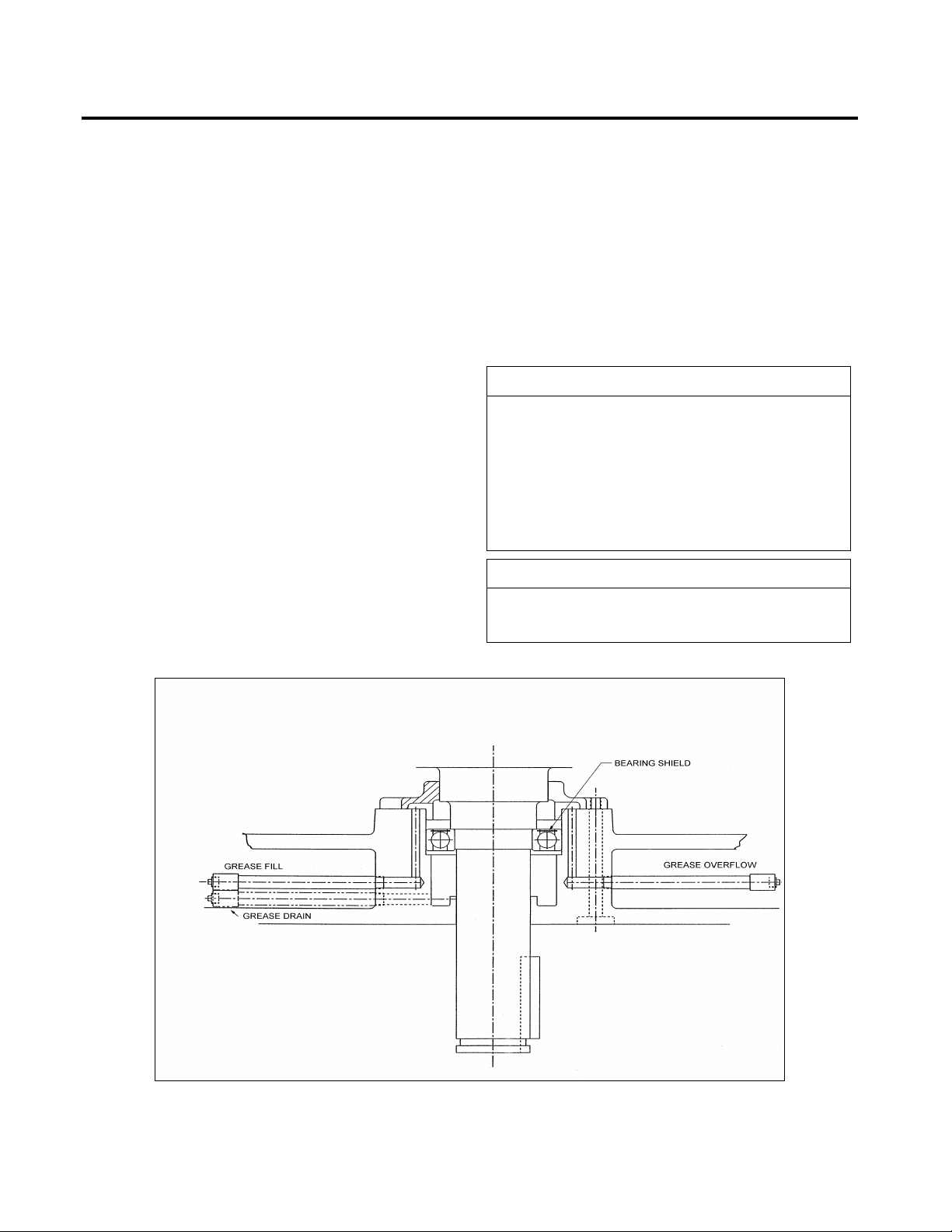
NOTE
inlet, overflow, and drain grease pipes.
NOTE
motor is run for some time.
For best results, grease sh ould be compounded of a
polyurea type and a good grade of petroleum oil an d
stabilized against oxidation.
The frequency of relubricating bearings and the
amount added each time depends on two factors speed and service.
All grease lube bearing motors will have affixed a
plate with lubricating ins tr u ctions . The instructions on
this plate should be followed to achieve optimum
bearing life and to avoid consequential damage to
rotating parts.
Relubricate with the type of grease specified on the
lubrication plate mounted on t he m otor, or compatible
grease. Mixing of non-compatible greas es c an c aus e
bearing failure.
Relubricate bearings with the proper gra de of grease
as follows:
1. Stop the motor and lock out the switch.
2. Thoroughly clean the grea se inlet fitting or plug.
If the motor has a plug, remove plug and clean
the inlet.
3. Remove the drain plu g (and overflow plug, if so
equipped) and clean out any hardened greas e.
4. Slowly pump the correct amount of grease into
the grease inlet, per the lubrication plate mounted
on the motor. Replace inlet plug (and overflow
plug, if so equipped).
5. Start motor and allow to ru n at least one (1) hour
to expel any excess grease from the drain
opening before re-installing the drain plug.
6. Stop the motor and lock out the switch.
7. Re-install the drain plug.
8. Put the motor back in operation.
If unit has been in operation for several years the old
grease can harden. If this occurs remove bolts
holding bottom inside end cap, raise end cap and
wipe out hardened grease. Reassemble and add a
small am ount of fresh grease.
If machine is a totally-enclosed or weather-protected
type disassembly of the lower bearing may be
required to remove old grease. Also clean and refill
Because the lower bearing is single shielded, the
grease will not pass through the drain port unless the
Figure 4
- 19 -
Page 21
Maintenance
SSU at
Typical
ISO VG
Bearing Type
300-350
68
Antifriction Bearing
700-800
150
Spherical Roller
300-350
68
Kingsbury
300-350
68
Sleeve Guide Bearing
Avoid adding oil while unit is running.
Bearing Lubricants - Oil
100°F
The preceding table lists “typic al” lubric ating oils onl y.
See the lubrication plate mounted on the motor for
the correct oil and relubrication frequency for your
motor.
Before starting the machine, fill bearing chamber to
the correct oil level as indic ated on the motor outline
drawing. Always fill through the pipe or plug at the
side of the motor. D o not overfill , as the oil m ay then
escape along the s haft and enter th e unit. T o change
oil, drain the oil reser voir by removing the pipe plug.
Clean and flush with solvent and refill with fresh
filtered oil every three to twelve months, depending
upon severity of service. Use a high grad e turbine oil
having a viscosit y indicated on the motor lubrication
data plate..
Always correct oil or water leaks and replace lost
lubricant promptly.
Oil
5. Angular contact type bearing r eplacements must
be equivalent in angle of contact. 40% contact
angle is standard.
6. The complete A.F.B.M.A. bearing number from
the motor nameplate.
Spherical Roller Bearings
External thrust transmitted from the driven unit is
normally carried b y the top beari ng. If replac em ent is
necessary, the new bearing must be the same type
as the original (See Figure 5).
CAUTION
Improper oil level reading may cause improper
lubrication of machine.
Bearing Replacement
Replacement bearings may be of a different
manufacturer; but m ust be equal to the or igina ls used
on the motor. See nameplate on unit or outline
drawing for bearing numbers. When ordering
bearings specify as follows:
1. Identify numerals and manuf acturer s tamp on the
bearing (number is also on motor nameplate).
2. Bearing Tolerance Class, i.e. (A.B.E.C.-1)
Annular Bearing Engineer’s Committee Tolerance Class One.
3. Electric motor quality.
4. If deep groove bearings, specify the internal
radial clearance, i.e. (A.F.B.M.A.-3) Antifriction
Bearing Manufacturers Association, Clearance
Class Three.
Figure 5
- 20 -
Page 22

Maintenance
Do not subject bearing to impact.
Protect the shaft end with a cap. If bearing is reusable,
the bearing and the puller hooks.
Figure 6. Removing Bearing with a Puller
Grease Repacking Table
Grease Quantity
Type
Operating
(Shaft)
Outer
Inner
Outer
Inner
Open
Groove
Angular
Contact
2/3
Full
1/3
Full
1/3
Full
2/3
Full
Single
Shielded
1/3
Full
1/3
Full
2/3
Full
1/3
Full
1/3
Full
2/3
Full
To Replace Bearings
1. Remove bolts holding bearing housing to yoke.
2. Remove bolts holding end caps to housings.
3. Remove end housings. Observe location of
bearing shims, and remove shims if necessary.
4. Remove snap ring or locknut in front of bearing.
5. Use bearing puller and exert force only on inner
race to remove bearing from shaft.
6. Check shaft and housing d iameter for proper size
with micrometer. Clean or replace inner bearing
cap, and slide cap onto shaft.
7. Heat the new bearing in an oven (200°F). W hile
hot, slide the bear ing onto shaft (high thrust un its
using angular contact beari ngs having a slip-fit on
shaft and need not be hea ted). Make certain the
inner race makes a firm even contact with shaft
shoulder.
8. Let bearing cool - if grease lubricated bearing,
pack caps per Grease Repacking Table with
proper grade of grease. Pack all open bearings
full between balls or rollers, but remove excess
grease from the outside of the retainers. Pack ing
of a cap or bearing h ousing c avity sho uld be don e
with a grease gun.
9. Before reassembling the top end cap after
installing new bearings, check the top edges of the
inner and outer races with a dial indicator for
squareness of mounting. To assure quiet
operation and good bearing life, total indicator
reading in each case must be within 0.001 in.
10. Indicate the outer race, attach the indicator body
to the shaft, allow the button to bear o n the outer
race, and then rotate the shaft slowly by hand.
11. Indicate the inner race, attach the indicator body
to the bearing bracket, all ow the button to be ar on
the top edge of the inner r ace, an d then r otate the
shaft slowly by hand.
12. Reinstall bearing shims; if used; reassemble end
caps and end housings.
CAUTION
Striking outer race exposes the race to brinelling
make certain the puller applies pressure against the
bearing inner race only. If puller will not hook the bearing
inner race, fabricate a split bushing and instal l it betw een
Bearing
Deep
Roller Vertical
Position
Vertical
Vertical
Vertical Full
Top End
Cap
2/3
Full
1/3
Full
Bottom End
Cap
1/3
Full
2/3
Full
Full
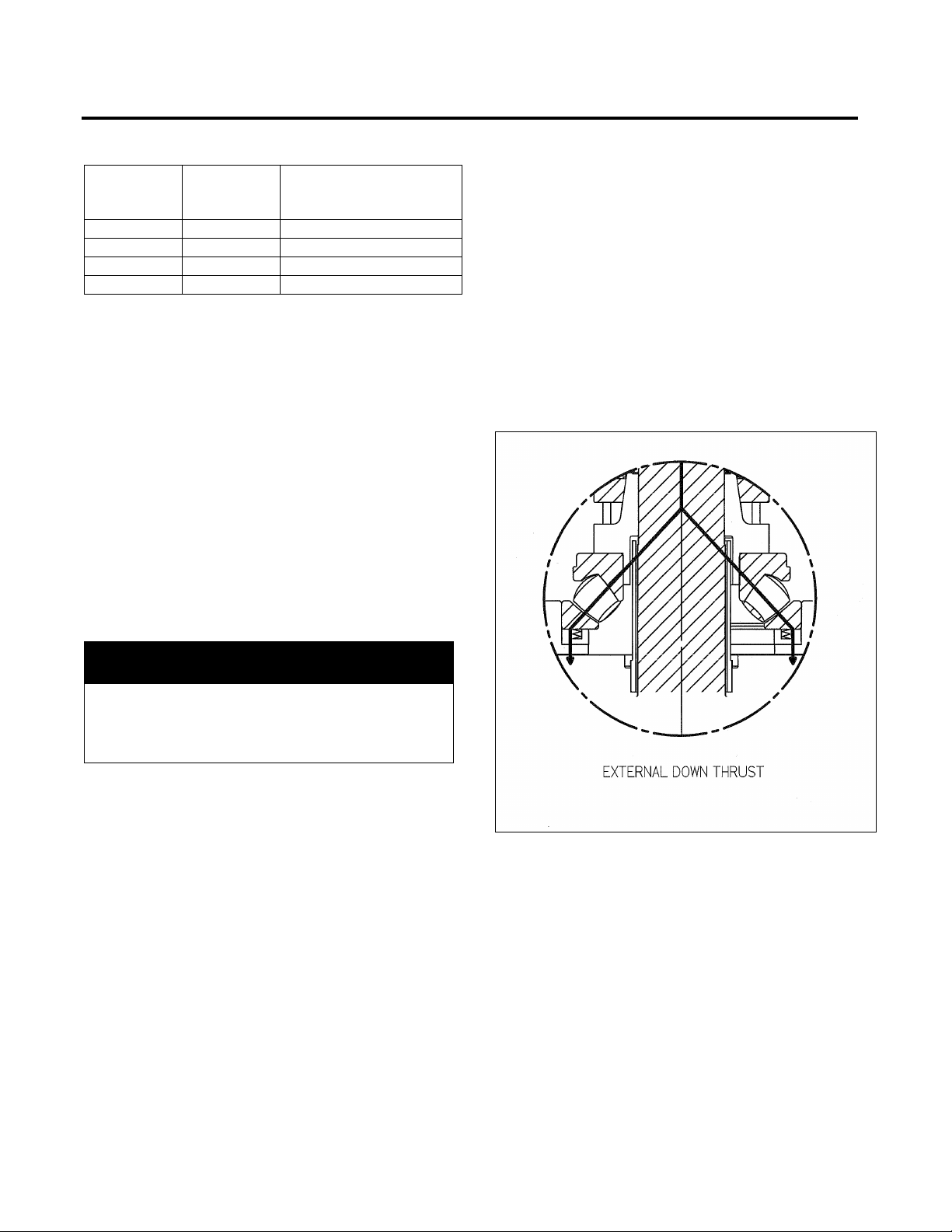
End Play
Machines designed for applications invo lving primarily
continuous heavy downthrust but having momentary
upthrust are equipped with angular contact or
spherical roller bearings. Spherical roller bearings
may be preloaded with springs (See Figure 8). The
end play is most often 0.005 to 0.0 08 in. but see the
motor outline for the exact value for your motor. The
bottom bearing takes the momentary upthrust and
prevents reverse loading of the top bearings. End
play is limited by shims when the thrust block is
shrunk on the shaft or b y tightening the locknut on the
shaft above the beari ng mounting sleeve. The thrust
bearings on 2 pole motors are mounted directl y on the
shaft and do not require an adjustment by the shims or
locknut.
- 21 -
Page 23

Maintenance
NOTE
(See Figure 8).
NOTE
as close to the babbitt as possible.
Upper Guide (Upthrust) Bearing
Spherical roller thrust bearings are spring loaded and
require a positive down thrust in addition to the rotor
weight to prevent up thrust on lower guide bearing
Measure axial end p lay by jacking the shaft upward
while measuring th e shaft axial m ovement with a dial
indicator attached to the upper bearing housing. For
motors with spring loaded spherical roller bearings,
the rotor end play will m ost often be downward. T he
downward rotor displacement can be measured by
jacking the rotor downward using a hydraulic jack
placed between the top of the shaft and a beam
fastened to the upper bearing housing.
When jacking the rotor upward or downward
CAUTION should be taken not to exert excessive
force on the rotor as this ma y dam age the end c ap or
add structural deflections to the axial end play
measurement.
Adjust the end pla y us ing shim s of proper design and
thickness under the end c ap of the lower bearing in
motors with shrink fit thrust block design or by
adjusting the thrust b lock travel by loosening the nut
above the thrust block in the slip fit thrust block
design. It is a good practice to check the end play
after final adjustments.
Kingsbury-type Bearings
Thrust Bearing
Principle elements of the Kingsbury-type thrust
bearing are the rotating thrust runner and the
stationary pivotal thrust shoes (See Figure 7) The
runner is the highly polished bottom surface of the
thrust block and receives the thrust load through a
massive nut above t he thrust block threaded on the
top end of the shaft. The pivotal thrust shoes are
faced with tin-hard Babbitt and machined to form an
accurate surface plate.
During operation, th e thrust bear ing rev olves in an oil
bath which covers the bearing. Each shoe is free to
tilt slightl y in any direction and sets its elf by pivoting
at a minute angle causing a wedge-shape d film of oil
to form between the shoe and the runner. An end
play of 0.012 – 0. 017 inches is preset at the factory
by shims between the thrust plate and the upper
guide (upthrust) bearing.
The upper guide (up thrust) bear ing with a Kingsburytype bearing is locate d just above the rotating thrust
runner and is mounted in the s tationary thrust plate.
This bearing is babbitted on the inside diameter
surface which bears on a ground and polished
surface of the thrust block. This bearing is also
babbitted on the bottom surface which bears on the
ground and polished surf ace of the thrust block. This
bearing locates the shaft in the radial direction and
transfers upthrust from the shaft through the thrust
block to the thrust plate. The thrus t bearing and the
lower half of the upper gu id e bear ing ar e im mersed in
oil. The upper portion of the upper guide bearing
receives oil through radial holes in the thrust block
and discharges oil thro ugh radial and hel ical grooves
in the guide bearing surface. The discharged oil is
deflected through the o il cooler tubes by an oil baffle
mounted on the bottom of the thrust plate.
Lower Guide Bearing
The function of the lower guide bearing with a
Kingsbury-type beari ng is to pr ovide rad ial locati on of
the shaft with no thr ust or end p lay lim it. This beari ng
may be one of three types – grease-lubricated ball
bearing, oil-lubricated ball bearing, or oil-lubricated
sleeve bearing (See Figures 9, 10 and 11).
Oil Operating Temperature
The normal temperature of the oil should be about
50°C to 70°C. The maximum safe temperature for
most bearings is 95°C to 100°C at the babbitt.
Bearing temperature should not be judged by feeling
the bearing with the hand; temperature should be
measured by a thermometer or thermocouple placed
The thrust bearing is cooled by water passing
through the heat exchanging copper tubes in the
bearing oil bath. The r ate of water f low is dependent
on water temperature, volume of oil, and the total
friction losses (load) of the bearing. Supply the
necessary amount of water required to cool the
bearing, but not to exceed the amount specified on
the outline drawing.
- 22 -
Page 24

Maintenance
the runner face
Allow time between starts to permit windings to cool.
To test the tubing for water-tightness empty the oil
reservoir, and if possible raise water pressure 50%
above normal and observe for a period of time for
leaks. Another way is to leave oil in reservoir,
pressurize tubes with air and look for bubbles.
If a hot bearing is disc ov er ed, or if the o il t emperature
climbs abnormall y fast, the c ause must be found and
corrected immediatel y. The most comm on causes of
hot bearings are:
1. Stoppage or reduction of cooling water.
2. Lack of oil (low oil level).
3. Contaminated (dirty) oil.
4. Misalignment (couplings or bearings).
5. Plugged oil passages.
6. Rough spots on shaft or bushings.
7. Improper internal clearances (radial or axial).
Installation / Inspection of Kingsbury-type
Thrust Bearings
Rotor Removal
1. Drain oil, unbolt and lift off the upper bearing
housing cover.
2. Unbolt inner end cap in lower bear ing hous ing .
3. Unbolt and remove outer end cap in lower
bearing housing.
4. Lift upper bearing housing along with the rotor
only far enough to reach the air deflector bolts by
using the openings provided in the housing
5. Unbolt air deflector and remove, if necessary.
6. Lift upper bearing and rotor completely free of
stator.
Thrust Bearing Removal
1. Support rotor weight at sh aft extension with jack
or block.
2. Unbolt and lift off upper bearing housing cover.
3. Unbolt thrust plate f rom bearing housing and lift
off thrust plate and upper guide bearing.
4. Remove lock nut from shaft and pu ll thrust block
from shaft.
5. Lift off the Kingsbury-type thrust bearing from
bearing housing or adapter ring.
Cleaning
All parts of the bearing and housings must be
thoroughly cleaned before as sem bl y.
Remove anti-rust co atings with an appro ved solvent.
Use lint-free rags or cloths for cleaning. Rem ove all
burrs, bruises or nicks, and rust from bearing
surfaces. Bruises or dents on shoe f aces should be
removed with a scraper.
Slight rusting of the runn er f ac e m a y be remove d with
a fine oil-stone. If deep rusting occurs, ref inishin g will
be necessary.
CAUTION
Indentations on face of bearing runner may cause
bearing failure or improper operation.
Never use a coarse-grained stone, scraper, or a file on
Assembly Notes: Do wels, keys, and b olts must not
bottom or bind. Each shoe should be free to tilt in
any direction. Oil th e runner face. Seal with Sil icone
RTV or equivalent, all housing joints previously
sealed.
Start Up: Make sure oil is at the pro per level (chec k
sight gauge). After the bearing has been turned a
few times under load, inspect the shoe faces - high
spots should be removed by scraping.
CAUTION
Excessive heat may cause damage to insulation or
lubrication.
- 23 -
Page 25

Maintenance
Figure 7
Figure 8
UPPER BEARING ARRANGEMENTS
- 24 -
Page 26

Maintenance
Figure 9
Figure 10
Figure 11
LOWER BEARING ARRANGEMENTS
- 25 -
Page 27

Maintenance
Self Release Coupling Arrangement At Top Of Motor
Figure 12
- 26 -
Page 28

Maintenance
NOTE
effect of bearing clearances.
Figure 13 – Shaft Runout Check
Figure 14 – Eccentricity and Face Runout Check
Shaft or Flange Face Runout
Because inspection of flange faces, eccentricity and
shaft runout is rigorously enforced at the factory,
vibrations caused by this alignment pr oblem are rare
and usually if shaft r unout, f ac e r uno ut, or ec c entricity
are excessive; the equipment has been m istreated in
some way.
The method f or chec king shaf t and flan ge fac es is as
follows:
On antifriction bearings, it is recommended that the
test be made with the shaft vertical to minimize the
Shaft Runout
The shaft runout is measured with the indicator
stationary with respect to the machine and with its
point at the end of the fin ished surface of the shaft.
See Figure 13 for typical fixture.
Read the maximum and minimum values on the
indicator as the shaft is rotated slowly through 360
degrees. The differ ence between the readings shall
not exceed 0.003 inches.
Eccentricity and Face Runout of
Mounting Surfaces
The eccentricity and face runout of the mounting
surfaces is measur ed with indicators m ounted on the
shaft extension. The point of the eccentricity
indicator shall be at approximately the middle of the
rabbet surface, and the point of the face runout
indicator shall be appr oximatel y the outer d iameter of
the mounting face. See F igure 14 for typic al fixture.
Read the maximum and minimum values on the
indicators as the shaft is r otated slowly through 360
degrees. The differ ence between the readings shall
not exceed 0.007 inches.
- 27 -
Page 29

Spare Parts
Identification
All units have an identif icat ion nam eplate af f ixed to the
frame (Figure 15). All the necessary information
pertaining to the motor can be found on this plate
including;
1. Serial Number
2. Type and Frame Size
3. Horsepower and Speed
4. Bearing Designations
It is important when or dering s pare parts or discus sing
service to have as much data from this plate as
possible.
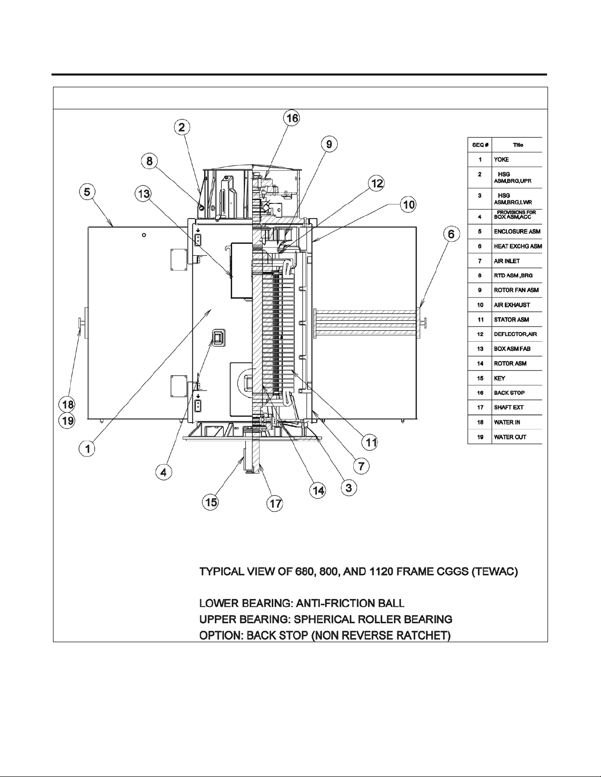
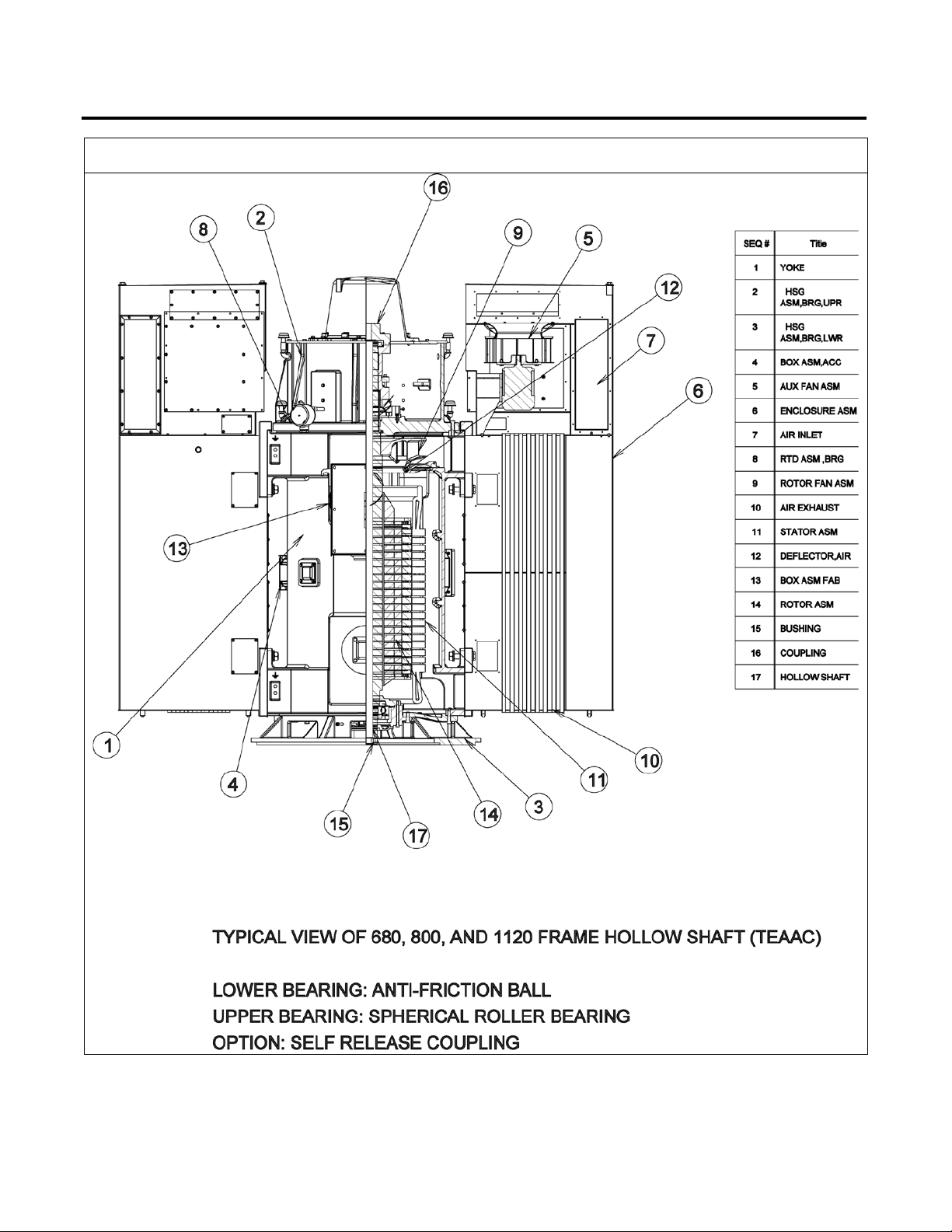
Parts Identification
Figures 16 through 20, are of a standard design. Your
motor may differ slightly.
A recommended list of spare parts is available upon
request.
Figure 15. Identification Plate
- 28 -
Page 30

Spare Parts
Figure 16
- 29 -
Page 31

Spare Parts
Figure 17
- 30 -
Page 32
Spare Parts
Figure 18
- 31 -
Page 33

Spare Parts
Figure 19
- 32 -
Page 34
Spare Parts
Figure 20
- 33 -
Page 35

Spare Parts
Vertical Solid & Hollow Shaf t
Nomenclature
Angular Contact Bearing - An antifriction thrust
bearing capable of taking high thrust in one axial
direction only.
DT Bearing - Two (2) angular contact bearings
mounted together to take extra high thrust in one
axial direction only.
DB Bearings - Two (2) angular contact bearings
mounted together such that each one will take high
thrust in opposite directions.
End Play - The axial movement of the shaft.
Four Point Bearing - An angular contact bearing
which will take thrust in both directions.
Guide Bearing - The bearing mounted in the
housing opposite the thrust bearing. Most are deep
groove antifriction bearings.
Thrust block or Bearing Mounting Sleeve - The
member keyed to the motor shaft on which the inner
race of the thrust bearing is mounted.
Continuous Down Thrust - The thrust developed by
the weight of the pump shaft and hydraulic
unbalance. This is the thrust value to which the
motor thrust bearings are sized.
Maximum Down Thrust - the momentary down
thrust that can be developed during shut down of
the pump.
Momentary Upthrust - This thrust may develop in
some shallow settings during startup. Momentary
upthrust is mostly carried by the Guide Bearing in
most vertical motors.
Non-Reverse Ratchet or Backstop - A device that
permits motor to turn in only one direction. It is
used mostly in conjunction with Rigid Coupl ings to
prevent turbine pump backspin caused by the water
column receding when the motor is de-energized.
Applicable to Hollow Shaft Only
Rigid Coupling or Bolted Coupling - The member to
which the pump shaft is keyed. Coupling is bolted
to the Thrust Block so that during startup the Guide
Bearing will carry the momentary upthrust.
Self-Release Coupling - Similar to the Rigid
Coupling except that it will release from the Thrust
Block in the event an accidental reversal begins to
unscrew the pump shaft. After being disengaged,
the motor is free to revolve without damage to the
motor or pump.
Coupling Bore or Clutch Bore - That bore or hole in
the coupling in which the pump shaft fits.
Pump Adjusting Nut - The nut mounted on the pump
shaft above the coupling used to raise and lower the
pump shaft to set the impeller to its proper position.
After the impeller is set, the nut is bolted to the
coupling. The nut is supplied by the pump
company.
Hold Down Bolts for Self-Release Coupling - Bolts
used to hold the coupling in place during shipment.
They must be removed during installation.
Locking Bar - A bar used to prevent the motor shaft
from turning while the pump adjusting nut is being
turned.
Pump Shaft Guide Bushing - A bronze bushing
pressed in a counterbored hole in the bottom of the
hollow shaft. This bushing supports the pump shaft
from lateral movement. Supplied only upon request.
NOTE: If the lower bearing is insulated this bushing
must also be insulated.
- 34 -
Page 36

Motor Service Record
Serial No
______________________
Horsepower
______________
Type
___________
°C
MACHINE TYPE
BEARINGS
SHAFT EXTENSION
Weather Protected
Date
Installed
Date Repaired
or Replaced
Repaired
by
Total
Cost
No. Per
Motor
Qty
Repl.
Qty
Repl.
Rotor
Stator Coils
Bearing, DE
Bearing, ODE
Other
INSPECTION
Date Checked
Bearings
Lubrication
Excess Heat
Excess Noise
Speed
Voltage
Amps
Insulation
Clean
Alignment
Vibration
Temperature
Speed
________
Insulation Class
Owner Order No
Horizontal
Vertical
Open Drip-Proof
Totally-Enclosed
Explosion Proof
Volts
_______
_____________
Temperature Rise
_________________
Ball Roller Sleeve
Size:
Drive End (DE) _____________ ___ __ ___
Opposite Drive End (ODE) ____________
Lubrication ___________________________
Location Application
Repairs or Parts Replaced
Amperes
_____________
_______
Item No
(1)
Fault
_____
Hertz
Frame Size
Date Of Manufacture
Length ___________________
Diameter _________________
Internal Thread ____________
External Thread ____________
Keyway __________________
_______
____________
_________
(1)
Name of Part
Siemens No. Date
Cost Date
Cost
- 35 -
Page 37

- 36 -
Notes
__________________________________________________________________________________________
__________________________________________________________________________________________
__________________________________________________________________________________________
__________________________________________________________________________________________
__________________________________________________________________________________________
__________________________________________________________________________________________
__________________________________________________________________________________________
__________________________________________________________________________________________
__________________________________________________________________________________________
__________________________________________________________________________________________
__________________________________________________________________________________________
__________________________________________________________________________________________
__________________________________________________________________________________________
__________________________________________________________________________________________
__________________________________________________________________________________________
__________________________________________________________________________________________
__________________________________________________________________________________________
__________________________________________________________________________________________
__________________________________________________________________________________________
__________________________________________________________________________________________
__________________________________________________________________________________________
__________________________________________________________________________________________
__________________________________________________________________________________________
__________________________________________________________________________________________
__________________________________________________________________________________________
Page 38

Siemens Industry, Inc.
Norwood Motor Plant
4620 Forest Avenue
Norwood, OH 45212-3396
(513) 841-3100
ANIM-03535-0814
(Supercedes all previous issues of ANIM-03535)
©2014 Siemens Industry, Inc. All rights reserved.
 Loading...