

Page 1
IP-Module
IP-Module CFVA-IP
IP-Module CVVA-IP
User manual
Issue 07/2005
Fire Safety & Security Products
Siemens Building Technologies
Page 2

Equipment availability and technical specifications subject to change without notice.
Data and design subject to change without notice. Supply subject to availability.
© Copyright by
Siemens Building Technologies AG
Wir behalten uns alle Rechte an diesem Dokument und an dem in ihm dargestellten Gegenstand vor. Der Empfänger anerkennt diese
Rechte und wird dieses Dokument nicht ohne unsere vorgängige schriftliche Ermächtigung ganz oder teilweise Dritten zugänglich machen
oder außerhalb des Zweckes verwenden, zu dem es ihm übergeben worden ist.
We reserve all rights in this document and in the subject thereof. By acceptance of the document the recipient acknowledges these rights
and undertakes not to publish the document nor the subject thereof in full or in part, nor to make them available to any third party without our
prior express written authorization, nor to use it for any purpose other than for which it was delivered to him.
Page 3

Contents
1 Introduction .............................................................................................5
2 General Safety Precautions ...................................................................6
3 Ordering data...........................................................................................7
3.1 Ordering data for IP-Module CFVA-IP ......................................................7
3.2 Ordering data for IP-Module CVVA-IP......................................................7
4 Norms and Directives .............................................................................8
5 Technical data .........................................................................................9
5.1 Technical data for IP-Module CFVA-IP.....................................................9
5.2 Technical data for IP-Module CVVA-IP ..................................................10
6 Installing the IP-Module........................................................................11
6.1 Installing IP-Module type CFVA-IP .........................................................11
6.2 Installing IP-Module type CVVA-IP .........................................................12
7 Establishing initial communication with the device..........................14
7.1 Changing the IP address of the client PC...............................................14
7.2 Mapping a network route ........................................................................14
8 Checking device accessibility .............................................................16
9 Device homepage .................................................................................17
9.1 Calling up the device homepage.............................................................17
9.1.1 Calling up the device homepage using Microsoft Internet Explorer .......17
9.1.2 Calling up the device homepage using the Web-Cam IP Manager........17
9.2 Components of the device homepage ....................................................19
10 Configuring network settings .............................................................. 20
10.1 Changing the device IP address.............................................................21
9.1.1. Changing the device IP address via the device homepage....................21
9.1.2 Changing the IP address using the Web-Cam IP Manager....................22
11 Configuring image parameters............................................................24
11.1 Configuring general image parameters ..................................................24
11.2 Configuring text overlay ..........................................................................24
11.3 Configuring JPEG encoder settings........................................................ 25
12 Setting the date and time .....................................................................27
13 Configuring user names and passwords ...........................................28
14 Restarting the IP Module......................................................................29
15 Live video...............................................................................................31
15.1 Displaying live video ...............................................................................31
15.2 Setting live video resolution ....................................................................32
15.3 Storing still pictures.................................................................................32
16 Establishing access to the device via internet ..................................33
17 Embedding live video images in a dedicated HTML page................35
18 Service mode.........................................................................................36
19 Index.......................................................................................................37
Siemens Building Technologies
Fire Safety & Security Products
3
Page 4

Page 5

1 Introduction
Thank you for deciding to buy this IP-Module.
We wish you every success in using this product. If you have any questions about
the product, please contact your local SIEMENS branch office.
This IP-Module allows you to display live video images from a dome camera on
your PC via an internet connection.
The live video images are transmitted via a TCP/IP based network and displayed
using an http browser (e.g. Netscape 7.0, Mozilla or Internet Explorer).
The image parameters and network settings of the dome camera can be
configured via the network.
About this manual
This user manual explains how to install and configure the IP-Module. Please read
the manual carefully to familiarize yourself with the device.
Introduction
Siemens Building Technologies
Fire Safety & Security Products
5
Page 6

General Safety Precautions
2 General Safety Precautions
Read these instructions carefully before connecting the camera and the IP-
Module in order to avoid damage caused by improper installation or use.
Installation may be done only by authorized personnel according to the local
safety regulations.
Operate the camera and the IP-Module only with the designated voltage.
Follow the safety instructions for the camera and for the IP-Module.
Never use the camera and the IP-Module for purposes other than those
designated.
Repairs and adjustments to the camera and the IP-Module may be done only by
authorized personnel.
If liquids or objects get into the housing, disconnect the camera and the IP-
Module from the power supply and have it checked by your authorized dealer
before using it again. (Danger of electric shock!)
This equipment has been tested and found to comply with the limits for a Class
B digital device. These limits are designed to provide reasonable protection
against harmful interference in a residential installation.
This equipment may generate, uses and can radiate radio frequency energy
and, if not installed and used according to instructions, may cause harmful
interference with radio communications.
Be aware that any modifications not explicitly approved in this manual may void
your equipment warranty.
The shielded interface cable recommended in this manual must be used with
this equipment in order to comply with the limits for a digital output device.
6
Siemens Building Technologies
Fire Safety & Security Products
Page 7

Ordering data
3 Ordering data
3.1 Ordering data for IP-Module CFVA-IP
Type Item no. Description Weight
CFVA-IP 2GF1086-8AL IP-Module for 12 V DC / 24
V DC indoor fix dome
camera
PSU230-12 2GF1800-8BE 12 V DC camera power
CAPA2410-P230 2GF1800-8BJ 24 V AC camera power
Extra accessories, not included in the standard
supply!
supply
supply
3.2 Ordering data for IP-Module CVVA-IP
Type Item no. Description Weight
CVVA-IP 2GF1185-8AG IP-Module for 12 V DC / 24
V DC vandal-proof fix dome
camera
PSU230-12 2GF1800-8BE 12 V DC camera power
CAPA2410-P230 2GF1800-8BJ 24 V AC camera power
Extra accessories, not included in the standard
supply!
supply
supply
0.40 kg
0.12 kg
0.30 kg
0.62 kg
0.12 kg
0.30 kg
Siemens Building Technologies
Fire Safety & Security Products
7
Page 8

Norms and Directives
4 Norms and Directives
EU Directive
The following applies for the device described in this manual:
The product satisfies the requirements of the EU Electromagnetic Compatibility
Directive 89/336/EEC. The EU declarations of conformity can be made available to
the relevant authorities by:
Siemens Building Technologies
Fire & Security Products GmbH & Co. oHG
Siemensallee 84
D-76187 Karlsruhe
Application in accordance with the Electromagnetic Compatibility Directive
The device has been designed for industrial use and satisfies the following
requirements:
Electromagnetic
emissions:
Electromagnetic
immunity:
EN 61000-6-3
EN 50130-4 +A2
8
Siemens Building Technologies
Fire Safety & Security Products
Page 9

Technical data
5 Technical data
5.1 Technical data for IP-Module CFVA-IP
Electrical supply 12 V DC/24 V AC
Power requirement max. 6.0 W
Operating temperature range -10 – +45 °C, max. relative humidity 90%
Storage temperature range -20 – +60 °C
Dimensions (H x Ø) 35.5 x 140 mm
Weight 400 g
Material Aluminum
System requirements All systems, which feature TCP/IP network functions and
provide an http browser (Microsoft Internet Explorer from
version 5.5 with Java plug-in or Mozilla or Netscape from
version 7.0).
Protocols ARP, BOOTP/DHCP, TCP/IP, HTTP, ICMP, SNMP, FTP
and DNS
Installation IP address configurable via ARP, BOOTP/DHCP,
connection to twisted-pair RJ45 Ethernet.
Network connection 10BaseT Ethernet or 100BaseTX Fast Ethernet, auto-
sensing, full/half duplex
Image formats QCIF (176x144),
CIF (352x288),
4CIF (704x576) (interlaced).
Image transmission Motion JPEG (multipart/x-mixed-replace content type),
user configurable JPEG single image frame quality,
streaming up to 25 images per second with QCIF and
CIF or up to 10 images per second with 4CIF.
Security Separate passwords for image access and system
configuration.
Hardware 8 MB RAM, 16 MB flash ROM
Siemens Building Technologies
Fire Safety & Security Products
9
Page 10

Technical data
5.2 Technical data for IP-Module CVVA-IP
Electrical supply 12 V DC/24 V AC
Power requirement max. 6.0 W
Operating temperature range -10 – +50 °C, max. relative humidity 90%
Storage temperature range -20 – +60 °C, max. relative humidity 70%
Dimensions (H x Ø) 48 x 135 mm
Weight 620 g
Material Aluminum
IP rating IP66
System requirements All systems, which feature TCP/IP network functions and provide an
http browser (Microsoft Internet Explorer from version 5.5 with Java
plug-in or Mozilla or Netscape from version 7.0).
Protocols ARP, BOOTP/DHCP, TCP/IP, HTTP, ICMP, SNMP, FTP and DNS
Installation IP address configurable via ARP, BOOTP/DHCP, connection to twisted-
pair RJ45 Ethernet.
Network connection 10BaseT Ethernet or 100BaseTX Fast Ethernet, auto-sensing, full/half
duplex
Image formats QCIF (176x144),
CIF (352x288),
4CIF (704x576) (interlaced).
Image transmission Motion JPEG (multipart/x-mixed-replace content type), user
configurable JPEG single image frame quality, streaming up to 25
images per second with QCIF and CIF or up to 10 images per second
with 4CIF.
Security Separate passwords for image access and system configuration.
Hardware 8 MB RAM, 16 MB flash ROM
10
Siemens Building Technologies
Fire Safety & Security Products
Page 11
6 Installing the IP-Module
6.1 Installing IP-Module type CFVA-IP
Installing the IP-Module
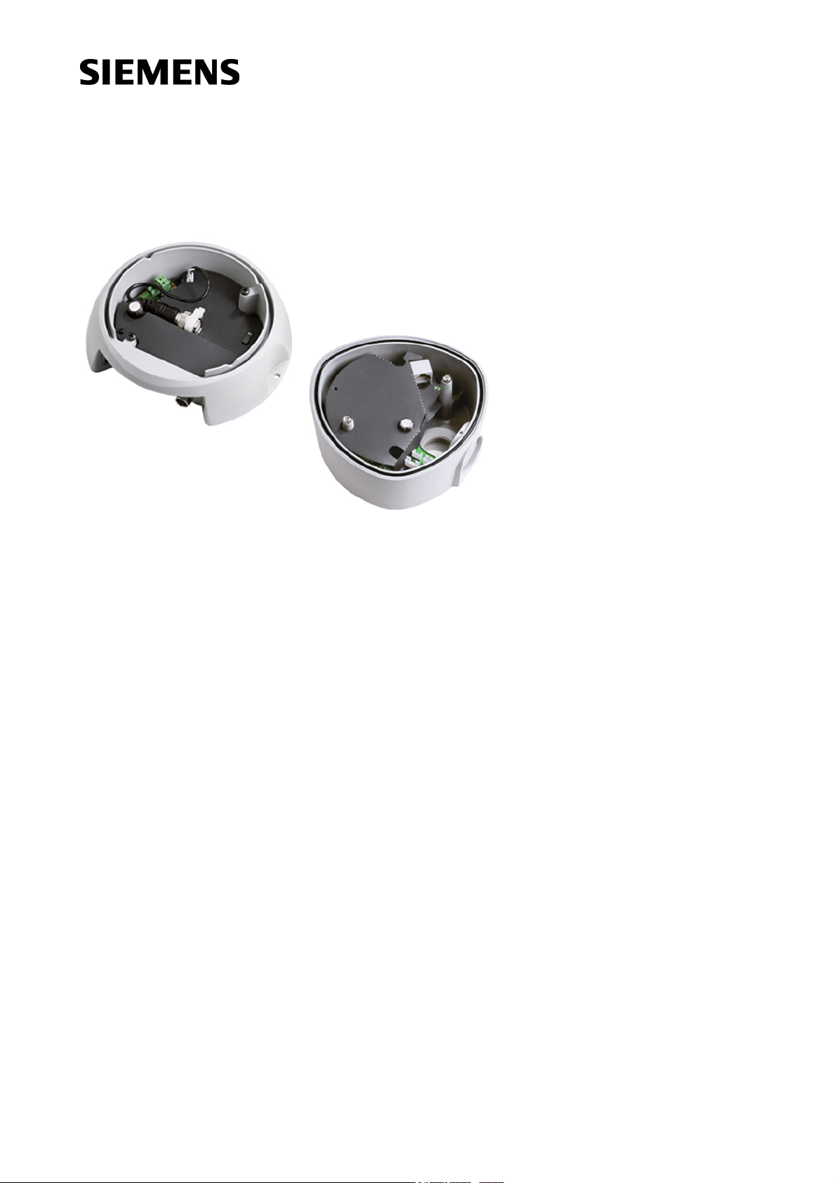
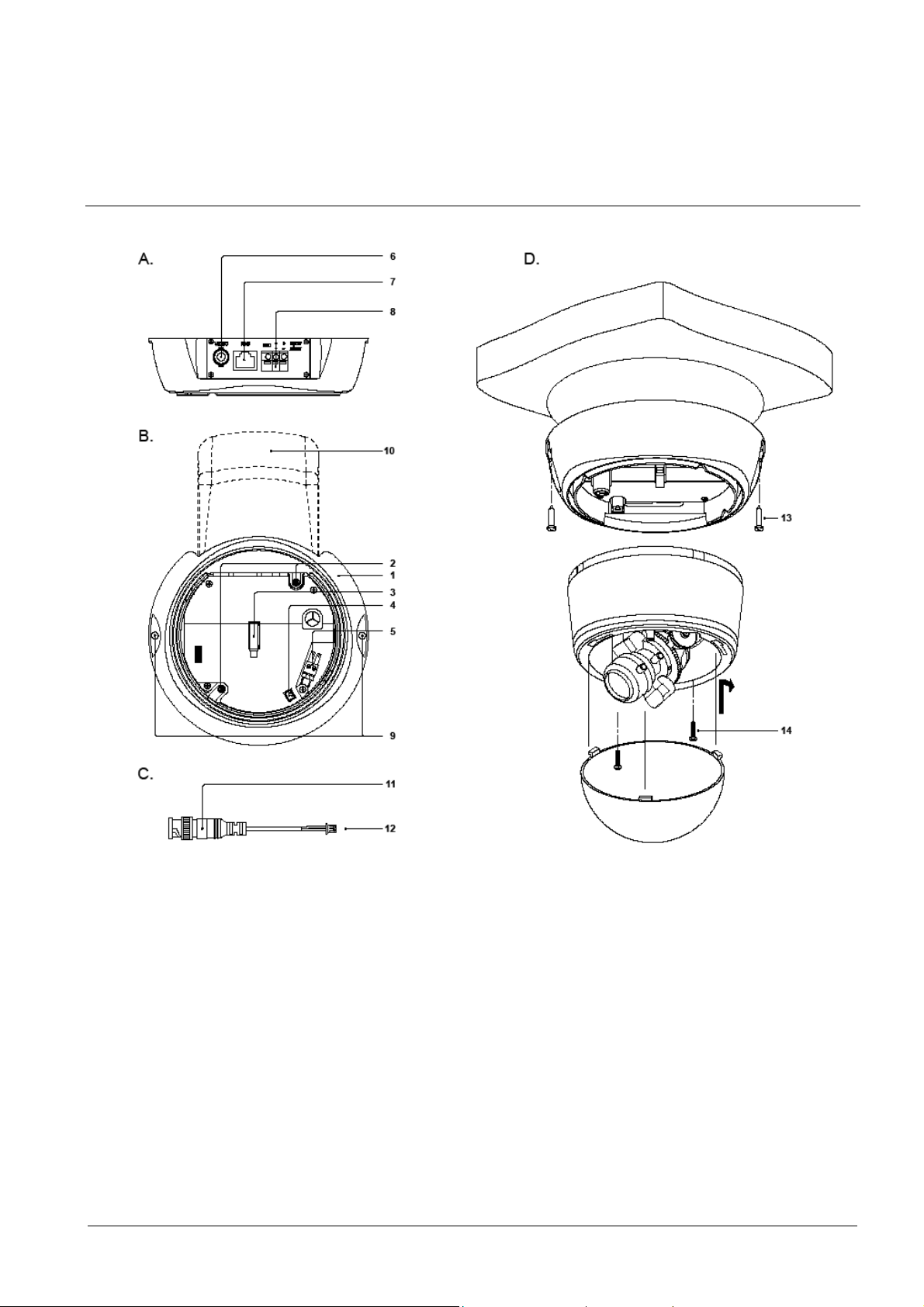
Fig. 1 Exploded view of IP-Module CFVA-IP
IP-Module fixing
1. Use the drilling template to drill two holes in the ceiling/wall and insert the wall
plugs.
2. Mount the IP-Module to the ceiling/wall.
3. Connect the BNC cable (12) to the connector socket (4) in the IP-Module.
Installation and connection of the dome camera
4. Connect the video output from the dome camera to the BNC cable video input
(11).
5. Connect the electrical supply for the dome camera to connector socket (5).
6. Remove the dome from the camera body (illustration D).
11
Siemens Building Technologies
Fire Safety & Security Products
Page 12
Installing the IP-Module
7. Place the camera body on the IP-Module and screw both units together using
the two screws supplied.
8. Connect the LAN cable to the RJ45 socket (7).
9. Connect the (12 V DC / 24 V AC) electrical supply (8).
WARNING
Ensure correct polarity if using a 12 V DC supply, as incorrect connection may
damage the dome camera or cause the unit to operate abnormally.
10. Establish communication with the device for the first time. See section 7:
Establishing initial communication with the device.
11. A test monitor can be connected to the BNC socket (6) when configuring the
camera.
12. Configure the dome camera as required. Refer to the dome camera manual for
set-up instructions.
13. Place the dome back on the camera and screw it in position.
Clean the dome after installation using a soft, lint-free cloth to remove dust and greasy finger marks.
6.2 Installing IP-Module type CVVA-IP
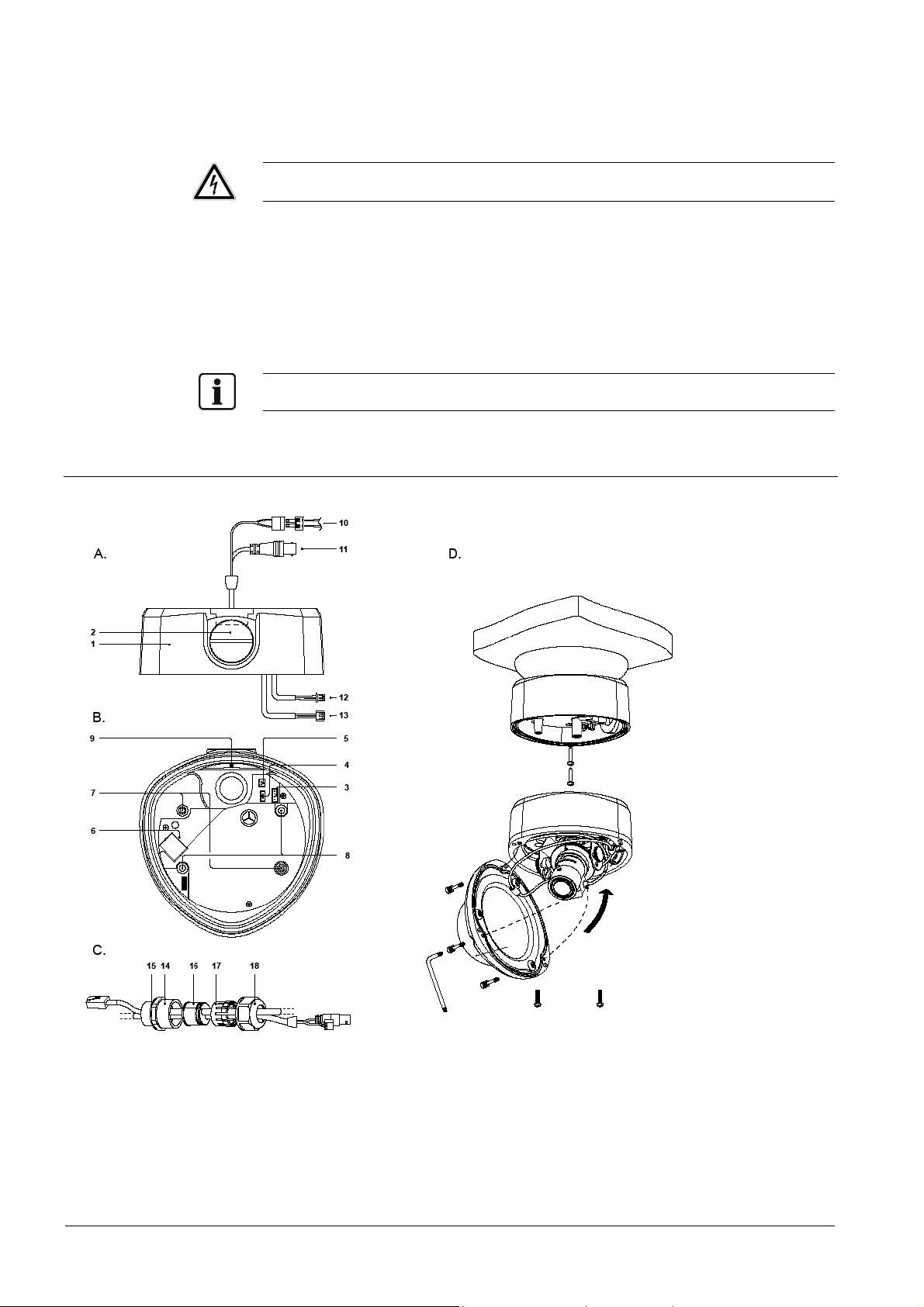
Fig. 2 Exploded view of IP-Module CVVA-IP
12
Siemens Building Technologies
Fire Safety & Security Products
Page 13

Installing the IP-Module
IP-Module fixing
The IP-Module features two apertures through which you can feed the cables:
An aperture in the base
An aperture in the side
If you wish to use the side aperture:
– Loosen the fixing screw (9) inside the IP-Module.
– Remove the blanking screw from the side cable aperture and screw this into the
cable aperture in the base of the unit.
1. Use the drilling template to drill two holes in the ceiling/wall and insert the wall
plugs.
2. If IP66 installation is required, use silicone sealant to seal the joint at the base of
the IP-Module.
3. Mount the IP-Module to the ceiling/wall.
4. If vandal-proof installation is required, protect the feed cables using suitable
protective conduits. Make sure you use a suitable 3/4" conduit on the cable
infeed. Seal the threads as required.
You can use the cable infeed arrangement supplied (illustration C) for other
applications.
5. Pass the cables (RJ45 LAN cable, electrical supply cable and BNC cable)
through the desired cable infeed (side aperture or base aperture).
6. Connect the LAN cable to the RJ45 socket (6).
7. Connect the Y cable supplied to the connector socket (3) in the IP-Module.
8. Connect the electrical supply to the connector socket (4).
9. If an analog video output is required, connect the outgoing BNC cable to the
BNC connection line (5).
Installation and connection of the dome camera
10. Open the dome housing (illustration D).
11. Gently pull the dome cables (electrical supply cable and BNC cables) out of the
dome camera.
12. Connect the Y cable lead (12) to the dome camera video output.
13. Connect the Y cable lead (13) to the dome camera video input.
14. Connect the (12 V DC / 24 V AC) electrical supply to the electrical supply cable
connection terminal (10).
WARNING
Ensure correct polarity if using a 12 V DC supply, as incorrect connection may
damage the dome camera or cause the unit to operate abnormally.
15. Place the camera body on the IP-Module and screw both units together using
the two screws supplied (7).
16. Establish communication with the device for the first time. See section 7:
Establishing initial communication with the device.
17. A test monitor can be connected to the BNC socket (11) when configuring the
camera.
18. Configure the dome camera as required. Refer to the dome camera manual for
set-up instructions.
19. Place the dome back on the camera and screw it in position.
Clean the dome after installation using a soft, lint-free cloth to remove dust and greasy finger marks.
13
Siemens Building Technologies
Fire Safety & Security Products
Page 14

Establishing initial communication with the device
7 Establishing initial communication with the device
The factory settings for the IP address and subnet mask are 192.168.100.100 and
0.0.0.0 respectively.
Communication between the device and the client PC is only possible if both the
client PC and the device are located in the same network segment. There are two
possible methods of achieving this:
Changing the IP address of the client PC. See section 7.1: Changing the IP
address of the client PC.
Mapping a network route. See section 7.2: Mapping a network route.
The service mode can be used to establish communication with the device if it is
no longer configured to use the factory-set IP address and the current IP address
is not known. See section 18: Service mode.
7.1 Changing the IP address of the client PC
WARNING
You must change the network settings of your client PC temporarily in order to
perform the following steps!
So make sure you note your original client PC settings (= original IP address
and original subnet mask setting).
1. Establish network connection via the Windows Start Menu Start > Settings >
Control panel > Network connections.
2. Right-click on the chosen connection and select Properties in the context menu.
3. Select Internet protocol (TCP/IP) in the "Properties" dialogue window and click
the Properties button.
4. Activate the check box for Use the following IP address in the "TCP/IP
properties" dialogue window.
5. Enter 192.168.100.101 for the IP address and 255.255.255.0 for the subnet
mask.
6. Click on OK.
7. Restart your client PC.
The client PC is now located in the same network segment as the device.
8. You must now allocate the desired IP address to the device via the device's
homepage. See section 10.1: Changing the device IP address.
9. If applicable, restore the client PC IP address to the original settings. Repeat
steps 1 to 7. When performing step 5, use your original client PC settings.
7.2 Mapping a network route
Mapping an appropriate network route informs the computer that it can reach IP
address 192.168.100.100 in its own network segment and does not need to use a
router.
Network routes can be set using the operating system "route" command. The exact
command syntax depends on the operating system used and may sometimes be
affected by the computer's hardware configuration. The following example is valid
for the Windows 2000 operating system:
First of all, enter the client PC IP address from which the device is to be accessed.
1. To do so, open the command prompt screen via the Windows Start Menu.
2. Type ipconfig and press the Enter key.
14
Siemens Building Technologies
Fire Safety & Security Products
Page 15

Establishing initial communication with the device
The client PC IP address is now displayed. In this example, we have assumed
IP address 10.11.12.13.
3. Type route add 192.168.100.0 mask 255.255.255.0 10.11.12.13 and press the
Enter key.
The ensuing network route ensures device accessibility.
Note that you should enter your own client PC IP address instead of
10.11.12.13.
4. Check that there is communication with the device by typing ping
192.168.100.100.
5. You must now allocate the desired IP address to the device via the device's
homepage. See section 10.1 Changing the device IP address.
15
Siemens Building Technologies
Fire Safety & Security Products
Page 16

Checking device accessibility
8 Checking device accessibility
Your device is accessed in the network via its IP address. The IP address is either
preset at the factory (IP address 192.168.100.100) or set by you when allocating a
new IP address to your device. See section 10.1: Changing the device IP address.
1. Type the following command in the your client PC's command prompt screen:
2. ping xxx.xxx.xxx.xxx
xxx.xxx.xxx.xxx = 192.168.100.100
if the IP address set by the factory is used
xxx.xxx.xxx.xxx = the IP address you have allocated to the device;
e. g. 141.73.31.3.
3. Press the Enter key.
16
Siemens Building Technologies
Fire Safety & Security Products
Page 17

Device homepage
9 Device homepage
9.1 Calling up the device homepage
There are two ways of calling up the device homepage:
Using Internet Explorer
Using the Web-Cam IP Manager
9.1.1 Calling up the device homepage using Microsoft Internet Explorer
1. Type the IP address that is allocated to the device in the http address line in
Internet Explorer. See section 10.1: Changing the device IP address.
e. g.:
http://141.73.31.3/
2. Press the Enter key.
The device homepage will be displayed.
9.1.2 Calling up the device homepage using the Web-Cam IP Manager
This assumes that:
The Web-Cam IP Manager and all the devices are located in the same network
segment. If a device and the Web-Cam IP Manager are not located in the same
network segment, you must ensure that associated gateway (router) passes the
SSDP multicast messages sent by the Web-Cam IP Manager to the network
segment where the device is located.
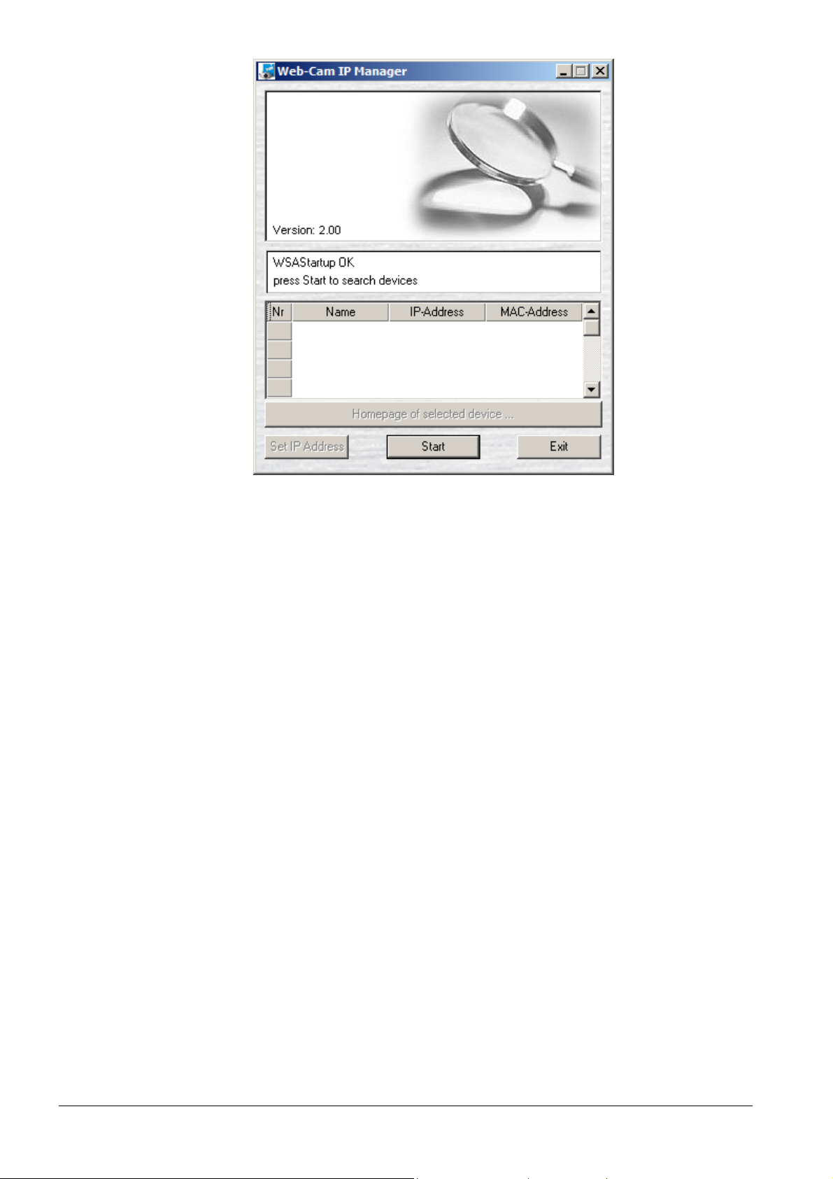
1. Start the Web-Cam IP Manager by loading IP Manager.exe. This application
can be found on the CD.
The Web-Cam IP Manager program window will open:
17
Siemens Building Technologies
Fire Safety & Security Products
Page 18
Device homepage
2. Click on the Start button.
The Web-Cam IP Manager program window will now display a list of all the
devices available for communication along with their IP addresses and MAC
addresses.
Each device's IP address or MAC address is unique.
3. Select the device whose homepage you want to call up.
4. Click on the Home page of selected device... button
The homepage of the selected device is now called up. See section 9.2:
Components of the device homepage.
18
Siemens Building Technologies
Fire Safety & Security Products
Page 19

9.2 Components of the device homepage
Device homepage
Fig. 3 Device homepage
1 Buttons for displaying live video images. See section 15.1: Displaying live video
2 Submenu
3 Language selection list box. Standard setting: English
4 Main menus
5 Display area for live video images. See section 15.1: Displaying live video
19
Siemens Building Technologies
Fire Safety & Security Products
Page 20

Configuring network settings
10 Configuring network settings
1. Call up the device homepage. See section 9.1: Calling up the device homepage.
2. Select Network settings in the Configuration menu.
The Network settings dialogue window opens:
Fig. 4 Network settings
3. Enter the desired settings in this dialogue window.
4. The settings are described in detail below.
5. Click on Save.
6. Restart your IP-Module. See section 14: Restarting the IP Module.
The network settings will be adopted.
Firmware Version Display of the Firmware Version
Hostname The hostname entered here appears in the Web Cam IP Manager as
Automatic network
configuration (DHCP)
IP-Address Enter the device IP address in this box. See section 9.1.1: Changing
Subnet mask Enter the device subnet mask in this box. See section 9.1.1: Changing
the name of the device. See section 9.1.2: Calling up the device
homepage using the Web-Cam IP Manager.
If you activate automatic network configuration, a DHCP or BOOTP
server will automatically allocate an IP address, a subnet mask and a
gateway to your device. See section 9.1.1: Changing the device IP
address via the device homepage.
the device IP address via the device homepage.
the device IP address via the device homepage.
20
Siemens Building Technologies
Fire Safety & Security Products
Page 21

Configuring network settings
Gateway (Next Hop) Enter the gateway IP address in this box. The gateway is the
MAC-Address Displays the network card ID.
Link Speed Choose the speed from the list. Automatic is the preferred setting.
computer in the network, which establishes the connection between
different network segments. If the device is only to be accessed by
other devices in the same network segment, enter 0.0.0.0 here.
10.1 Changing the device IP address
There are two ways of changing the device IP address:
Changing the device IP address via the device homepage.
Changing the IP address using the Web-Cam IP Manager
If the current IP address setting is not known, communication with the device can
be re-established in the service mode. See section 18: Service mode.
9.1.1. Changing the device IP address via the device homepage.
There are two methods of allocating a new IP address to the device using the
device homepage:
Automatic address designation by the DHCP or BOOTP server
By allocating an IP address manually
Automatic address designation by the DHCP or BOOTP server
1. Call up the device homepage. See section 9.1: Calling up the device homepage.
2. Select Network settings in the Configuration menu.
The Network settings dialogue window opens:
3. Activate the Automatic network configuration (DHCP) check box
Each time the device is restarted, the DHCP or BOOTP server will automatically
reinstate the network settings (IP address, subnet mask and gateway, if
applicable).
4. Restart your IP-Module. See section 14: Restarting the IP Module.
Manual IP address and subnet mask allocation
1. Call up the device homepage. See section 9.1: Calling up the device homepage.
2. Select Network settings in the Configuration menu.
The Network settings dialogue window opens:
3. Enter the device IP address in the IP-Address box.
The IP address is made up of four numbers in the range 0 - 255, which are
separated from each other by decimal points. The IP address must be
compatible with an existing network and a given address may only be allocated
to one device. In the case of new networks, which do not use the official internet
address space, we recommend you use the ranges 192.168.x.x and 10.x.x.x.
Each x represents a number in the range 0 to 255. If the device is to be
connected directly to internet, you must use an officially registered IP address,
which will be notified to you by your internet service provider. See section 16:
Establishing access to the device via internet.
4. Enter the device subnet mask in the Subnet Mask box.
21
Siemens Building Technologies
Fire Safety & Security Products
Page 22

Configuring network settings
Like the IP address, the subnet mask also consists of four numbers in the range
0 – 255, all separated from each other by decimal points. The subnet mask tells
the device which other IP addresses in the connected network (subnet) can be
dialed directly and which addresses have to be dialed through the gateway. To
indicate this, the target IP address is logically linked to the network mask by an
AND expression and the result compared to the logical AND-link between the
device's own IP address and the network mask. If these match, the target device
is located in the same network segment. Many networks use 255.255.255.0 as
the value for the network mask.
5. Enter the gateway in the list box. See section 10: Configuring network settings.
6. Restart your IP-Module. See section 14: Restarting the IP Module.
Example
If you set the device IP address to, for example, 141.73.31.3 and the subnet mask
to 255.255.255.128, the device can be accessed by a client PC with IP address
141.73.31.162 (and subnet mask 255.255.255.128). The client PC IP address and
that of the device are both located in the same network segment.
9.1.2 Changing the IP address using the Web-Cam IP Manager
You may only change the device IP address in the first 20 minutes after initial start-up.
This assumes that:
The Web-Cam IP Manager and all the devices are located in the same network
segment. If a device and the Web-Cam IP Manager are not located in the same
network segment, you must ensure that associated gateway (router) passes the
SSDP multicast messages sent by the Web-Cam IP Manager to the network
segment where the device is located.
1. Start the Web-Cam IP Manager by loading IP Manager.exe. This application
can be found on the CD.
The Web-Cam IP Manager program window will open:
2. Click on the Start button.
The Web-Cam IP Manager program window will now display a list of all the
devices available for communication along with their IP addresses and MAC
addresses (printed on the underside of the device).
22
Siemens Building Technologies
Fire Safety & Security Products
Page 23

Configuring network settings
Each device's IP address or MAC address is unique.
3. Select the device whose IP address you want to change.
4. Click on the Set IP Address button.
The following dialogue window opens:
5. Either manually enter the desired IP address, subnet mask and gateway (if
required), or activate the check box if you want the DHCP server to determine
these parameters.
The settings will be adopted immediately.
This process takes about 40 seconds. Next, the device homepage will be
displayed, allowing you to check the entries in Network settings in the
Configuration menu.
23
Siemens Building Technologies
Fire Safety & Security Products
Page 24

Configuring image parameters
11 Configuring image parameters
11.1 Configuring general image parameters
1. Call up the device homepage. See section 9.1: Calling up the device homepage.
2. Select Image parameters in the Configuration menu.
The Image parameters dialogue window opens:
3. Enter the desired settings in this dialogue window.
Brightness Live video image brightness (0% to 100%)
Contrast Live video image contrast (0% to 100%)
Saturation Live video image saturation (0% to 100%)
Flip picture Activate the check box to rotate the image through 180 degrees (the image now
appears upside down).
4. Click on Save.
11.2 Configuring text overlay
1. Call up the device homepage. See section 9.1: Calling up the device homepage.
2. Select Image parameters in the Configuration menu.
The Image parameters dialogue window opens:
3. Enter the desired settings in this dialogue window.
Name Enter a name for the video source here. This is the name that will be
overlaid on the live video image if you have activated the appropriate
setting.
24
Siemens Building Technologies
Fire Safety & Security Products
Page 25

Configuring image parameters
Overlay text You can select the parameters that are to be overlaid on the live video
Overlay text position You can select the position of the text overlay on the live video image
Overlay text color Choose the color for the text overlay here.
image here.
The following options are available:
– (no text overlay)
Time
Time and date
Video source
Video source and time
Video source + time + date
here.
The following options are available:
Top left
Top right
Bottom left
Bottom right
The following options are available:
White
Yellow
Pink
Red
Turquoise
Green
Blue
Black
11.3 Configuring JPEG encoder settings
The live video image can be displayed at the following resolutions:
Low
Standard
High
You can allocate a quality level to each resolution.
The table below shows guideline values in kilobytes for the size of data stream
required for image transmission. The size of the data stream depends on the
resolution setting and the chosen quality level.
Image size Low quality Medium quality High quality
176 x 144 4 KB 5 KB 12 KB
352 x 288 9 KB 11 KB 34 KB
704 x 576 26 KB 37 KB 137 KB
The values shown relate to a color image of average complexity.
1. Call up the device homepage. See section 9.1: Calling up the device homepage.
2. Select Image parameters in the Configuration menu.
The Image parameters dialogue window opens:
25
Siemens Building Technologies
Fire Safety & Security Products
Page 26

Configuring image parameters
3. Enter the desired settings in this dialogue window.
4. Select the quality level for each resolution from the options in the Quality list
5. We recommend you to set the quality level to Medium.
6. Select the font size for the text overlay from the options in the Diplay Font Size
– (no text overlay)
Small
Large
7. Select the input signal from the options in the Video Standard list box.
PAL/CCIR
NTSC/EIA
8. Click on Save.
box.
list box:
The following options are available:
The following options are available:
26
Siemens Building Technologies
Fire Safety & Security Products
Page 27

12 Setting the date and time
1. Call up the device homepage. See section 9.1: Calling up the device homepage.
2. Select Date and Time in the Configuration menu.
The Date and Time dialogue window opens:
Fig. 5 Date and time
The time and date that were current when the device start page was loaded
appear in the relevant boxes.
You can set the device's built-in real-time clock here.
3. Choose the desired settings from the list of options for each field.
4. Click on Save.
Setting the date and time
27
Siemens Building Technologies
Fire Safety & Security Products
Page 28

Configuring user names and passwords
13 Configuring user names and passwords
You can define user names and passwords for device configuration and image
access (live image access rights).
Factory set user names
For configuration:
– User name: config
For image access:
– User name: image
1. Call up the device homepage. See section 9.1: Calling up the device homepage.
2. Select Security in the Configuration menu.
The Security dialogue window opens:
Fig. 6 Security
3. Enter the desired user name (max. 32 characters).
4. Enter the desired password (max. 32 characters).
5. Confirm the password.
6. Click on Save.
28
Siemens Building Technologies
Fire Safety & Security Products
Page 29

14 Restarting the IP Module
Certain settings changes (e.g. network settings) will only come into effect after a
device restart.
1. Call up the device homepage. See section 9.1: Calling up the device homepage.
2. Select Restart in the Configuration menu.
The Restart dialogue window opens:
Restarting the IP Module
Fig. 7 Restart
There are three ways of performing a restart:
Manual restart
Time controlled restart
Restart by Ping Watchdog
Manual restart
1. Click on the Restart now button.
The device will restart immediately.
The device requires about 40 seconds for the restart. No communication can
take place with the device during this period.
Time controlled restart
1. Activate the Enable time controlled restart check box.
2. Enter the time in the box (HH:MM), e. g. 12:00.
3. Click on Save.
The device will restart at the set time every day.
4. Restart the device to adopt the new settings.
29
Siemens Building Technologies
Fire Safety & Security Products
Page 30

Restarting the IP Module
The watchdog is not active when the camera transmits a video stream.
1. Activate the Enable restart by Ping-Watchdog check box.
2. Enter the IP-Address of the Gateway (Next Hop) in the Remote Host to Ping
box. See Fig. 4: Network settings.
3. Enter the desired cycle time in seconds in the Frequency box, e. g. 30.
Restart by Ping Watchdog
The device will ping the Remote Host to Ping you have entered every 30
seconds.
4. Enter the desired cycle time in seconds in the Timeout box, e. g. 125.
A restart will be triggered if the return ping from the Remote Host for Ping you
have entered is not received within 125 seconds.
The time-out value must be a multiple of the cycle time (the value entered in
Frequency).
In the event of an unexpected system problem, this ensures the device becomes
available again after 2 to 3 minutes.
5. Restart the device to adopt the new settings.
30
Siemens Building Technologies
Fire Safety & Security Products
Page 31

15 Live video
15.1 Displaying live video
The data stream consists of individual JPEG-coded images, separated from each
other by markers (boundaries).
The software automatically selects the best possible live video display modus for
the browser that is used:
Netscape and Mozilla support multipart JPEG. In this case, the live images are
displayed directly without the use of an extra plug-in.
As Internet Explorer does not support the multipart JPEG format, Java applets
are used to display the live images.
This assumes that:
You have installed a Gecko-based browser (Mozilla, Netscape 7+). This
browser can be downloaded from:
http://mozilla.org/, http://netscape.com/download/.
Or
You have installed Microsoft Internet Explorer (5.5 or later). This browser can
be downloaded from:
http://microsoft.com/windows/ie/
In addition to Microsoft Internet Explorer (5.5 or later), you will need to install
Java Runtime. Java Runtime can be found on the CD supplied.
Live video
Displaying live video
1. Call up the device homepage. See section 9.1: Calling up the device homepage.
The live video image is displayed using the standard settings:
31
Siemens Building Technologies
Fire Safety & Security Products
Page 32

Live video
1 Resolution submenu
2 Text overlay. See section 11.2: Configuring text overlay.
3 Display area for live video
4 Status.
Playing
Pause
5 Pause button
Switches from live video display to still picture display
6 Display live video button
Switches from still picture display to live video display
15.2 Setting live video resolution
Select the size of the live video display window in the Resolution submenu (as a
function of the selected image quality).
The following options are available:
Low
QCIF, 176 x 144 pixels
Standard
CIF, 352 x 288 pixels
High
4CIF, 704 x 567 pixels
The default resolution is Standard.
The image quality is set in Image Parameters in the Configuration menu. See
section 11.1: Configuring general image parameters.
15.3 Storing still pictures
You can store still pictures in JPG and BMP format.
1. Click on the Pause button.
2. Choose Save image to in the context menu (right-click with the mouse).
The Save image dialogue window opens.
3. Indicate the storage location and the image file name here.
4. Click on the Save button.
32
Siemens Building Technologies
Fire Safety & Security Products
Page 33

Establishing access to the device via internet
16 Establishing access to the device via internet
If it is necessary to be able to access your device via Internet, you must ensure
that your IP address is internet-enabled. An Internet Service Provider (ISP) can
supply you with an internet-enabled IP address. The ISP will offer you static or
dynamic IP addresses.
Connecting to internet
Fig. 8 Connecting to internet
Static IP address
The ISP will supply you with an IP address once only. This address does not
change.
Dynamic IP address
Shared IP addresses are normally used when accessing internet through an
ISP. Your router will be allocated dynamic IP addresses for internet access by
your ISP, i.e. when dialing in via an ISP, the client (the computer attempting to
make the connection) will automatically be assigned a temporary, free IP
address when logging on. This means that the client acts as an internet server
for the time it is on-line.
The term 'dynamic' means that the connection to the ISP will be broken off
briefly at regular intervals, every 24 hours for example. When the connection is
re-established, your IP address may have changed. When the connection is
terminated, this IP address becomes available for use by another device and is
allocated to another connection that is established via the ISP. When the
33
Siemens Building Technologies
Fire Safety & Security Products
Page 34

Establishing access to the device via internet
connection is interrupted, the newly allocated IP address must be assigned to
your domain name, e.g. <www.myWebCam.de> , so that your device can still be
accessed using your domain name.
Example of access using a dynamic IP address
Requirements:
Your device is part of a local network (LAN) and is connected to internet by a
ROUTER, e.g. a TDSL router.
An ISP (Internet Service Provider) has already allocated you an IP address.
An ISP (Internet Service Provider) has already allocated you a domain name.
You have assigned an IP address to your domain name via a DNS server.
Establishing access to the device via internet
1. Allocate a fixed IP address to your device, e. g. 192.168.100.100. See section
10.1: Changing the device IP address.
2. Set the time and duration of the dynamic IP address change cycle used by the
ISP via the router.
3. Register your domain name with a Domain Name Server (DNS) e.g.
www.DynDns.org, so that the IP address can be assigned to the domain name.
Each time the connection to the ISP is reestablished, your router will be notified
of the new IP address. The router must be configured to notify the DNS of the
new IP address as soon the router receives it.
If it is now attempted to establish a connection to your domain name,
www.myWebCam.de for example, the connection to your router will be built up
via your ISP. The router must be configured to pass all incoming requests to the
device.
34
Siemens Building Technologies
Fire Safety & Security Products
Page 35

Embedding live video images in a dedicated HTML page
17 Embedding live video images in a dedicated HTML
page
Live video images cannot be embedded using Microsoft Internet Explorer!
The live video images delivered by the device can be embedded in dedicated
HTML pages using the following HTML tag, e. g.:
<IMG SRC="http://192.168.1.100/cgi-bin/livejpeg" BORDER=8>
Changing live video image parameters
The parameters are hung behind the URL for embedding the images as follows:
For example: http://192.168.1.100/cgibin/livejpeg?Parameter1=value1&Parameter2=value2
The table shows the available parameters:
Embedding live video images
Parameter Settings
size Image size
szX Image width in pixels
szY Image width in pixels
ofX Image offset, measured horizontally from the left-hand side of the digital image
ofY Image offset, measured vertically from the top edge of the digital image
qual JPEG coding quality in the range 0-100
bw Black/white display properties
limit Band width limit in kilobits per second
size=0 QCIF input (176 x 144),
size=1 CIF input (352 x 288),
size=2 4CIF input (704 x 576),
1: black/white,
0: color
Tab. 1 Changing parameters
Example for an executable HTML page
<!DOCTYPE HTML PUBLIC "-//W3C//DTD HTML 4.0 Transitional//EN">
<html>
<head>
<title> Show Live Video with a resolution of 352*288</title>
<head>
<body>
<img src="http://141.73.46.35/cgi-bin/livejpeg?size=1>
<body>
<html>
Embedding still pictures
Still pictures can be embedded in a dedicated HTML page as follows, e. g.:
<IMG SRC="http://192.168.1.100/cgi-bin/livejpeg" BORDER=8>
Use the parameters in the table above.
35
Siemens Building Technologies
Fire Safety & Security Products
Page 36

Service mode
18 Service mode
The service mode allows the device IP address to be reset even if the IP address
that is currently allocated to the device is not known.
If, for example, the Automatic Network Configuration (DHCP) option is activated
when communication with the device is first established, the device will
automatically be allocated an IP address by the DHCP server following each
restart. This address is not known prior to the event and can change each time a
restart takes place. Devices configured in this way can normally be accessed via
the Web-Cam IP Manager. See section 9.1.2: Calling up the device homepage
using the Web-Cam IP Manager.
However, if you are unable to call up the device via the Web-Cam IP Manager (this
can occur when the gateway (router) fails to pass SSDP multicast messages to the
device), you will have no other means of accessing the device as the IP address is
not known. The only recourse is to reset IP address in the service mode.
Proceed as follows to reset the IP address in the service mode:
Requirements:
The device's MAC Address must be known. Your device's MAC address is printed
on a sticker on the device itself.
1. Open your PC's command prompt screen via the Windows Start Menu and use
the following command to create a static link between the desired IP address
and the device's MAC address (must occur within 60 seconds):
arp –s IP address MAC address
e.g: arp –s 192.168.1.100 00-d0-4a-00-10-01
The IP address you use must be located in the same network segment as the
client PC that you have used to create the link. If in doubt, refer to the following
example: The client PC's IP address is 192.168.1.1 and the subnet mask is
255.255.255.0. You should allocate IP address 192.168.1.100 to the device. The
subnet mask setting of 255.255.255.0 is automatically used in the service mode.
In this example, 00:d0:4a:00:10:01 is assumed to be the device's MAC address.
2. Interrupt the electrical supply and withdraw the LAN cable from the device.
3. Reconnect the electrical supply to the device. The device will switch to service
mode after 40 seconds. The device will enter the service mode for 60 seconds.
4. Reconnect the LAN cable to the device.
5. You can now set the IP address using the ping command (e.g. ping
192.168.1.100). Successful adoption of the IP address setting is indicated when
the ping command indicates that data packages are returning to the client pc.
6. An IP address allocated in this way will only remain valid until the next time the
device is restarted. For this reason, you should now re-assign a permanent IP
address to the device via the device homepage. See section 9.1.1: Changing the
device IP address via the device homepage.
36
Siemens Building Technologies
Fire Safety & Security Products
Page 37

19 Index
Index
A
Accessibility
Checking device accessibility, 16
B
Brightness
Configuring brightness, 24
C
Contrast
Configuring contrast, 24
D
Declaration of conformity, 8
Device homepage
Calling up the device homepage, 17
Components of the device homepage, 19
E
EMC Directive, 8
EU Directive, 8
Exploded view IP-Module
Exploded view of IP-Module CFVA-IP, 11
Exploded view of IP-Module CVVA-IP, 12
F
Flip picture, 24
I
Image parameters
Configuring image parameters, 24
IP address
Changing IP address of client PC, 14
changing the device IP address, 21
IP Module
Restarting the IP Module, 29
IP-Module
Installing CFVA-IP, 11
Installing CVVA-IP, 12
J
JPEG encoder settings
Configuring JPEG encoder settings, 25
L
Live video
Displaying live video, 31
Live video images
Embedding live video images in a dedicated
HTML page, 35
N
Network route
Mapping a network route, 14
P
Password
Configuring passwords, 28
R
Resolution
Setting live video resolution, 32
S
Saturation
Configuring saturation, 24
Service mode, 36
Setting date and time, 27
Storing still pictures, 32
T
Text overlay
Configuring text overlay, 24
U
User name
Configuring user names, 28
37
Siemens Building Technologies
Fire Safety & Security Products
Page 38

Herausgegeben von
Siemens Building Technologies
Fire & Security Products GmbH & Co. oHG
D-76181 Karlsruhe
www.sbt.siemens.com
Dokument Nr. A24205-A336-B383
Ausgabe 07.2005
Liefermöglichkeiten und technische Änderungen vorbehalten.
Siemens Building Technologies AG
© Copyright by
Gedruckt in der Bundesrepublik Deutschland
auf umweltfreundlich chlorfrei gebleichtem Papier.
 Loading...