

Page 1
SIEMENS
CF62 Level 2 Service Manual
BE INSPIRED
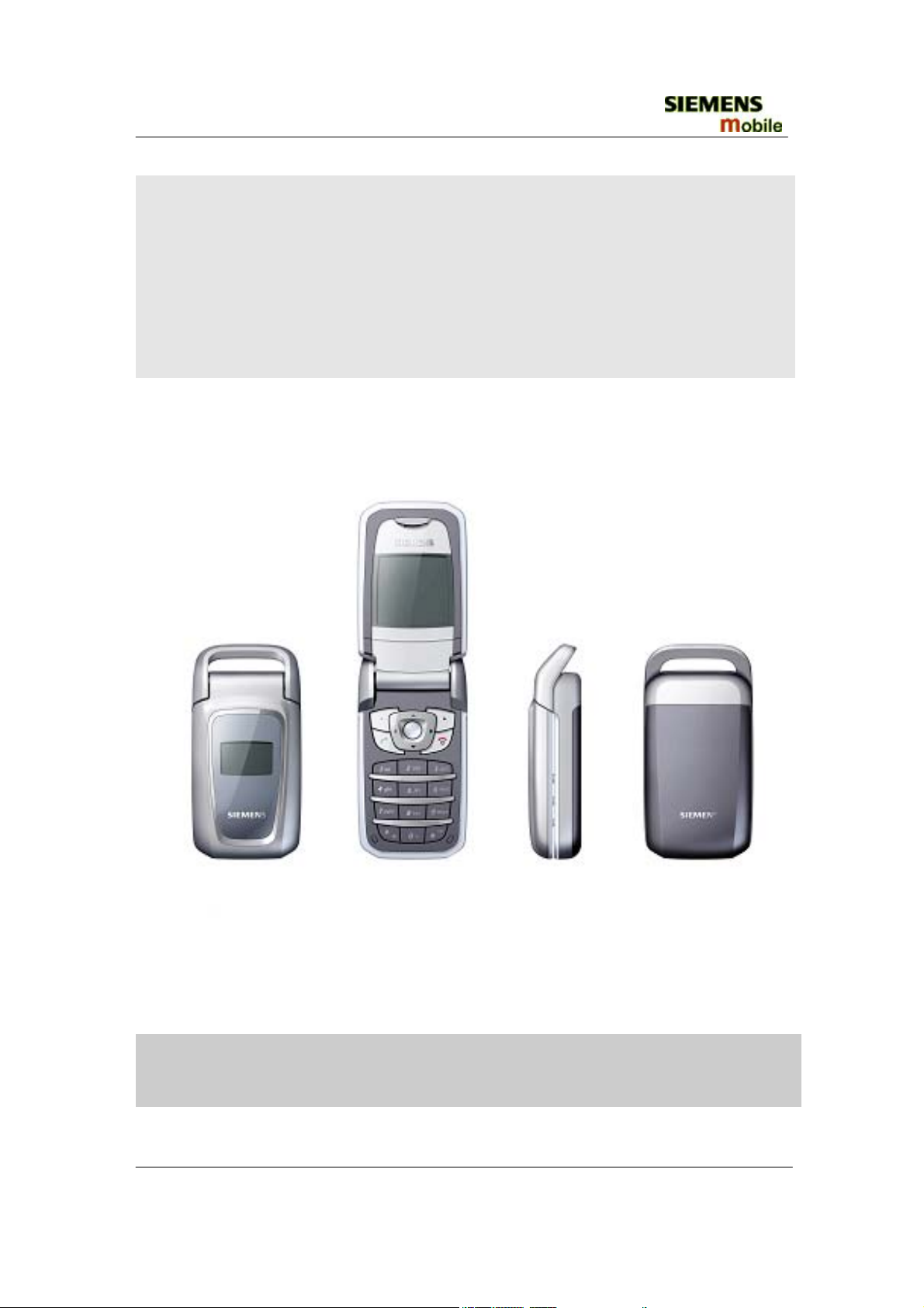
CF62 Leopard
Clean & distinctive design
Copyright © Siemens Mobile
All rights reserved
Siemenes Shanghai Technical Support Center
1 of 42
SSMC MD CCQ
Internal Service Use Only
Page 2
SIEMENS
CF62 Level 2 Service Manual
Table of Content
1 Cellular Communication ……………………………………………………….. 3
1.1 Coverage Concept ………………………………………………………… 3
1.2 GSM Network Architecture ……………………………………………… 4
1.3 Subscriber Identity Module ……………………………………………… 5
1.4 WAP ( Wireless Application Protocol )
…………………………………..
1.5 GPRS (GENERAL PACKET RADIO SERVICE) …………………….. 7
1.6 K-JAVA APPLICATION …………………………… ………………….. 8
2 CF62 Technical Information
…………………………………………….………
2.1 Key Features ………………………………………………………………9
2.2 Comparison With Previous Products ……………………………………10
3 Accessories……………………………………………………………………….. 11
4 Unit Description CF62 Leopard .............................................................……12
4.1 Assembling concept for the customer .................................................. 12
4.2 Interface CF62 Leopard to accessories ……………………...…………. 12
4.3 Exploded view of CF62 Leopard ………………………… ……………… 13
4.4 Handset parts and defined service parts …………………………………15
4.5 PCB top-side ……………………………………………………………… 16
4.6 PCB bottom-side …………………………………………………………. 16
5 Disassembly of CF62 Leopard ……………………………… …………………...17
6 Assembly of CF62 Leopard ………………………………………………………23
7 Mobile Software Programming ………………………………………………….27
7.1 Introduction …………………………………………………………………27
7.2 Mobile Software Updating …………………………………………………28
7.3 Flow chart for S/W upgrading ………………………………….………….29
8 Siemens Service Equipment User Manual ………………………….……………30
9 JPICS (Java based Product Information Controlling System)………………….31
10 International Mobile Equipment Identity, IMEI ……………………………….36
11 General Testing Information …………………………………………………….37
Annex 1………………………………………………………………………………….41
6
9
Annex 2………………………………………………………………………………….42
Copyright © Siemens Mobile
All rights reserved
Siemenes Shanghai Technical Support Center
2 of 42
SSMC MD CCQ
Internal Service Use Only
Page 3
SIEMENS
T
CF62 Level 2 Service Manual
1 Cellular Communication
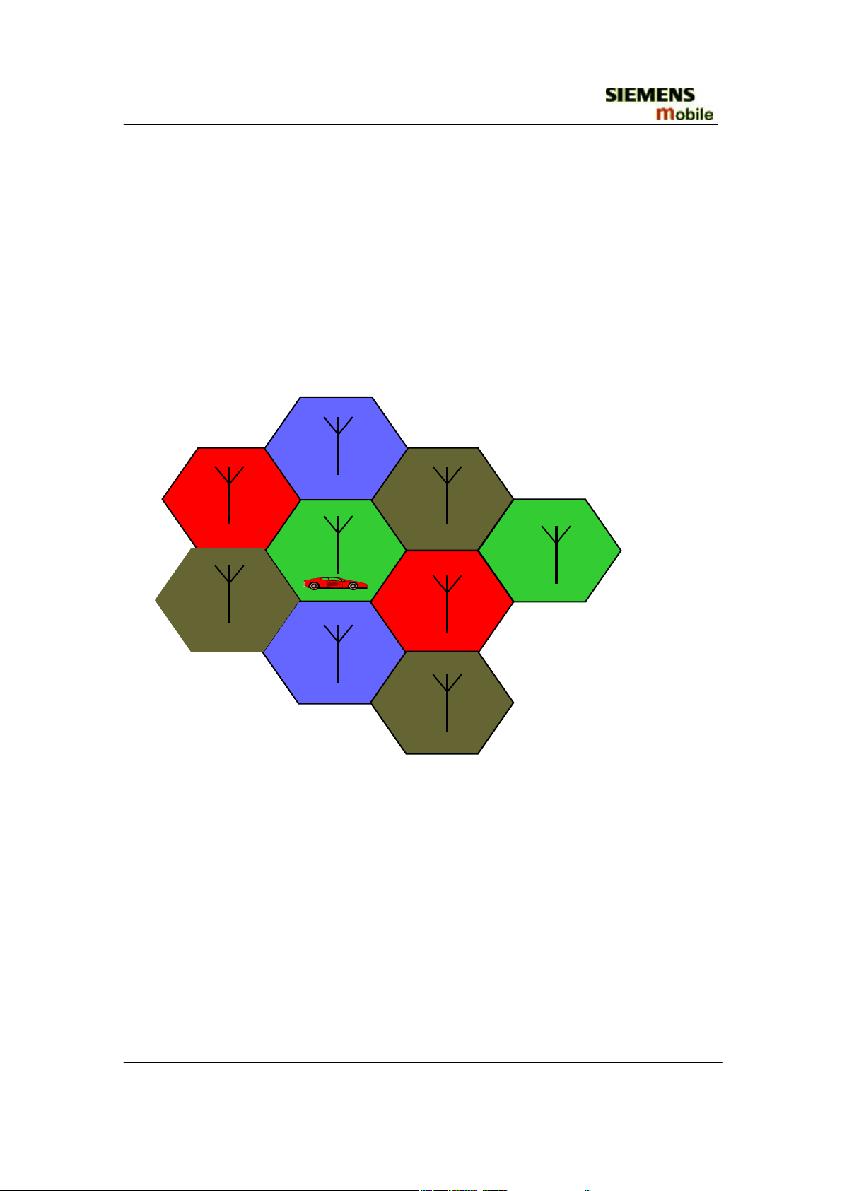
1.1 Coverage Concept
he cellular systems is made up of numerous transmitting and receiving sites, whose
individual coverage areas partially overlap. The concept of frequency re-use, same
frequency is used by several sites, allows a high traffic density in a wide area. Due
to the limited transmission range of the terminals, cellular systems are based on a
large number of base stations on the infrastructure side, scattered over the area to cover,
with each covering a fairly small geographical zone called cell. Cells are often
represented by hexagons (see figure 1.1.).
Figure 1.1 CELLULAR COVERAGE REPRESENTATION
Copyright © Siemens Mobile
All rights reserved
Siemenes Shanghai Technical Support Center
3 of 42
SSMC MD CCQ
Internal Service Use Only
Page 4
SIEMENS
CF62 Level 2 Service Manual
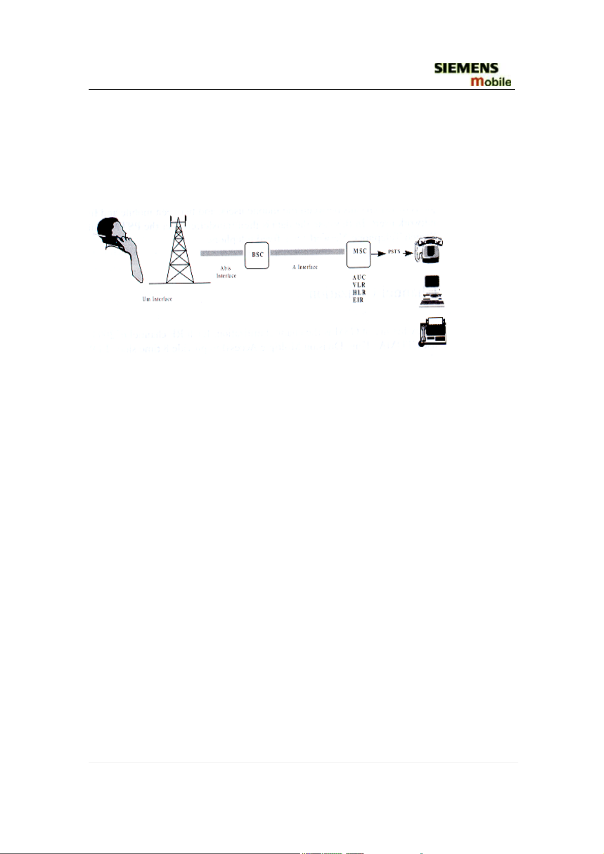
1.2 GSM Network Architecture
GSM network can be broadly divided into three broad parts, namely:
1. Mobile Station(MS) carried by the subscriber
2. Base Station Sub-system(BSS) which controls the radio link with the mobile station.
3. Mobile Switching Center(MSC) which performs the switching of calls between the
mobile users, and between mobile and fixed network users.
FIGURE 1.2 GSM ARCHITECTURE
Each mobile station is given a unique identity. As soon as the mobile phone is turned on,
it registers with the network and is authenticated, as such the network could always find
the mobile phone. Larger amount of data is being exchanged to and from the following
functional blocks in the MSC:
Visitor Location Register, VLR
Contain relevant data of all mobiles located in the serving MSC, but not belong to the
area.
Home Location Register, HLR
Stores identity and user data of all the mobile users belonging to the area.
Authentication Center, AUC
Provides the HLR with different sets of parameters to complete the authentication of the
mobile station.
Equipment Identity Register, EIR
An option the network operator can use to enforce security. With this feature the network
can identify defective or stolen mobile that may not be used in the network.
Copyright © Siemens Mobile
All rights reserved
Siemenes Shanghai Technical Support Center
4 of 42
SSMC MD CCQ
Internal Service Use Only
Page 5
SIEMENS
CF62 Level 2 Service Manual
1.3 Subscriber Identity Module (SIM)
SIM is a smart card which has a computer and memory chip that is permanently installed
in the mobile equipment. It comes in either the size of a credit card or smaller version
known as the plug-in SIM.
SIM card using 5V technology is not supported.
The subscriber information, which includes a unique number called the International
Mobile Subscriber Identity (IMSI) is stored in the SIM card. SIM card identifies the
subscriber to the network.
To protect the SIM card from improper use, a security feature, a four digits personal
identification number (
by the subscriber. PIN2 Is required for additional functions available with a special SIM
card (Consult the operator for more Information about the PIN 2).
A code (PUK) is provided for unlocking the SIM card if the SIM card is blocked
.
), is built in. The PIN is stored in the card and can be changed
PIN
Copyright © Siemens Mobile
All rights reserved
Siemenes Shanghai Technical Support Center
5 of 42
SSMC MD CCQ
Internal Service Use Only
Page 6
SIEMENS
CF62 Level 2 Service Manual
1.4 WAP ( Wireless Application Protocol )
Wireless Application Protocol takes a client-server approach that uses the in-built microbrowser to make a request, in wireless markup language (
WML
service. The request is passed to a WAP Gateway, which then retrieves the information
from a Internet server, in HTML format, and translate it into WML. The requested
information is then sent to from the
WAP
Gateway to
WAP
available and most appropriate mobile network bearer services.
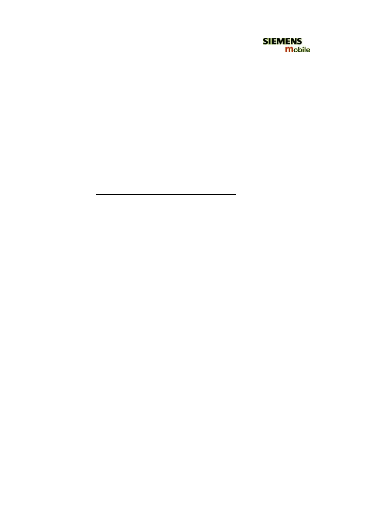
Wireless Protocol Stack.
Wireless Application Environment (WAE)
Wireless Session Protocol (WSP)
Wireless Transaction Protocol (WTP)
Wireless Transport Layer Security (WTLS)
Wireless Datagram Protocol (WDP)
Bearers e.g. Data, SMS, USSD
TABLE 1.1 WAP PROTOCOL STACK
1. Wireless Application Environment
Defines the user interface on the phone. WAE contains the WML,WML,script and
the wireless telephony application (WTA).
2. Wireless Session Protocol
Link the WAE to two session services – one connection oriented operating above the
WTP and a connectionless service operating above WDP.
3. Wireless Transaction Protocol
Runs on top of the datagram service and part of the standard suite of TCP/IP
protocols, to provide a simplified protocol suitable for low bandwidth mobile station.
4. Wireless Transport Layer Security
WTLS incorporates security features that are based upon the established Transport
layer Security (TLS) protocol standard, that include data integrity checks, privacy on
the WAP Gateway to client leg and authentication.
5. Wireless Datagram Protocol
Allows
laying bearer. WDP presents a consistent data format to the higher layer on the WAP
stack.
WAP Internet access via the CF62 is possible with the inclusion of Wireless Application
Protocol (WAP) browser 1.2.1.
to be bearer independent by adapting the transport layer of the under-
WAP
), for information or
client (mobile) using the
Copyright © Siemens Mobile
All rights reserved
Siemenes Shanghai Technical Support Center
6 of 42
SSMC MD CCQ
Internal Service Use Only
Page 7
SIEMENS
CF62 Level 2 Service Manual
1.5 GPRS (GENERAL PACKET RADIO SERVICE)
GPRS is a new non-voice value added services that a llows information to be sent and
received across a GSM mobile telephone network. It supplements today’s Circuit Switched
Data (CSD) and Short Message Services (SMS). GPRS involves overlaying a packet based
air interface on the existing circuit switched GSM network. This gives the option to use a
packet-based data service. The information is split into separated but related “packets” before
being transmitted and reassembled at the receiving end. Theoretically, maximum speeds of
up to 171.2 kilobits per second (kbps) are achievable with GPR S using all eight timeslots at
the same time. This is about 3 times as fast as the data transmission speed possible over
today’s fixed telecommunications networks and 10 times as fast as current Circuit Switched
Data services on GSM networks
.
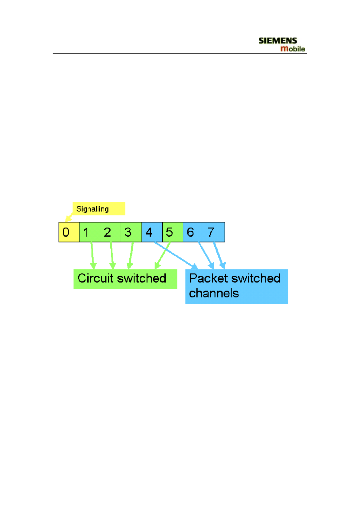
Example: Cell with 1 Frequency channel:
1 physical channel for signaling, 4 physical channels for Circuit switched and 3 physical
channels
for Packet switched.
Copyright © Siemens Mobile
All rights reserved
Siemenes Shanghai Technical Support Center
7 of 42
SSMC MD CCQ
Internal Service Use Only
Page 8
SIEMENS
CF62 Level 2 Service Manual
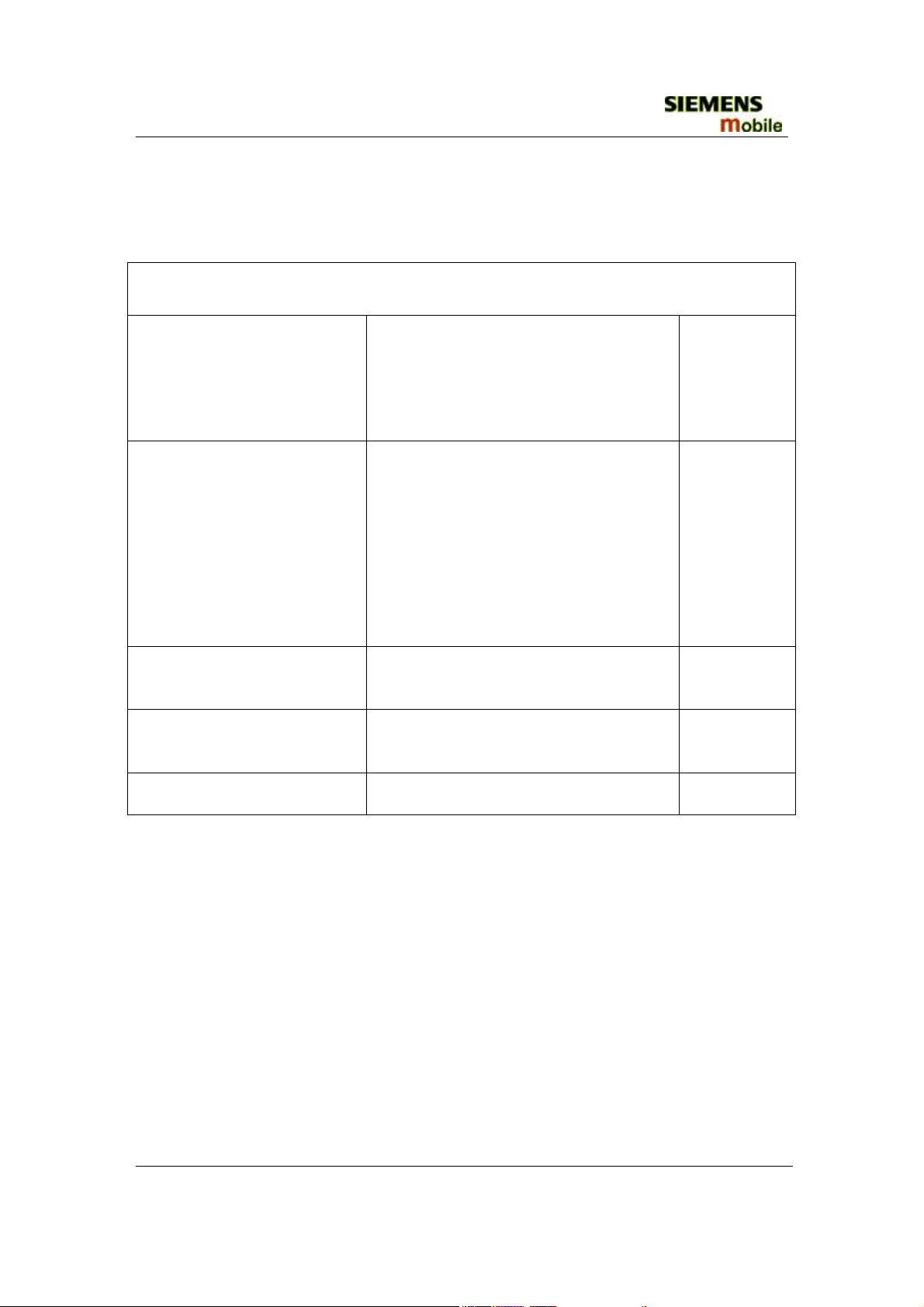
1.6 K-JAVA APPLICATION
Java-based game system
Java Application Manager
(JAM)
RAM for Java applications
MIDP 1.0, CLDC 1.0
‘OEM extensions’
HTTP API over GPRS
Application launcher and download
manager.
yes
Supports HTTP-based OTA
download of applications over GPRS
and CSD.
Available RAM for Java applications
(i.e. Program code and data) during
yes
application runtime:
Minimum 100 Kbytes (Has to be
taken as working assumption for
application development).
Goal: 145 Kbytes as SL45i (not
committed).
As SL45i, including performance
optimizations from SL45i-Infusio.
yes
Proprietary API extension as SL45i.
Including ‘Siemens Game API’.
yes
Sl45i: only CSD yes
Copyright © Siemens Mobile
All rights reserved
Siemenes Shanghai Technical Support Center
8 of 42
SSMC MD CCQ
Internal Service Use Only
Page 9
SIEMENS
CF62 Level 2 Service Manual
2 CF62 Technical Information
2.1 Key Features
System/Standards:
Volume:
Weight:
Antenna:
General:
Battery:
Stand-by Time:
Talk Time:
SIM Card:
Speech Coder:
Main Display:
Sub Display:
Keypad:
• Triple-band
• GSM900/1800/1900
• US:850/1800/1900
•
78cm3
•
85g
•
External Loop
•
SMS, EMS & MMS
• Java MIDP 1.0
• GPRS Multislot Class 10
•
WAP 1.2.1, parts of 2.0
•
Hands free operation
•
Lilon Battery Pack 600mAh
• Power Input:2A(0.6ms)/0.25A(4ms)
• Cut-off Threshold 3.2V
• Up to 220 h
•
Up to 5 h
•
Small (=”Plug in”) 1.8V or 3V-SIM card(Phase II).
•
Half Rate ,Full Rate, Enhanced Full Rate and Adaptive Multi
Rate speech coders are available as standard.
• Type: Full Graphic
•
Resolution: 130 X 130 Pixel
• Technology: CSTN
• No of Colours: 64K
• Frame Rate: 15 frames/sec
•
Pixel size /mm: 0.21mm X 0.21mm
• Active area /mm: 27.3mm X 27.3mm
• Illumination: White (3 LEDs integrated)
• Type: Full Graphic
•
Resolution: 64 X 96 Pixel
• Technology: STN
• No of Colours: Black & White
• Frame Rate: 15 frames/sec
•
Pixel size / mm: 0.21mm x 0.21mm
• Active area / mm: 20.2mm x 13.4mm
• Illumination: Blue (2 LEDs integrated)
• backside-printed-foil-technology
•
12-key-block (0-9, #, *)
• two function keys (SEND, END)
• ON/OFF key combined with the END key; the symbol (I
inside O) is used as a symbol for ON/OFF.
Copyright © Siemens Mobile
All rights reserved
Siemenes Shanghai Technical Support Center
9 of 42
SSMC MD CCQ
Internal Service Use Only
Page 10
SIEMENS
CF62 Level 2 Service Manual
• 4 way-navikey
•
2 soft-keys for different SW-enabled functions
• tactile finder on key “5“
• 11 amber LEDs for keypad
Night Design:
Acoustics:
• 7 amber LEDs for magic ring
• Three-in-one-earpiece for handset, handsfree and ringing
tones
• Omnidirectional microphone
•
Loud signal emitter (soundringer) (>100dB(A) SPL @5cm,
'Hongkong-Spec.') only for rectangular sound signals (NOT
POSSIBLE for Soundringer melodies)
• Polyphonic ringer tones 16 voices
• different selectable volume levels for handsfree, handset and
ringer mode (for the amount see SW product description)
2.2 Comparison With Previous Products
Feature A60 Lion AE65/A66 Leopard
Triple Band
Triple Band
Supported Systems
EGSM900/GSM1800/GSM19
00
Stand-by Time Up to 250 h Up to 220 h
Talk Time Up to 5 h Up to 5 h
Battery Technology
Battery Capacity
Li-Ion Battery Pack
NOMINAL CAP:700 MAH
Weight Approx. 85 g Approx. 85 g
Volume Approx. 91 cm3 Approx. 78 cm3
Length 110 mm 81.5 mm (w/o Antenna)
EGSM 900/GSM1800/
GSM1900 (EMEA, APAC)
GSM 850/GSM1800/
GSM1900 (NAFTA)
Li-Ion Battery Pack
NOMINAL CAP:600 MAH
Width 47 mm 45.2 mm (max.)
Thickness 23 mm 21.9 mm (max.)
SIM Plug-In 3V Plug-In 1.8V/3V
Antenna Integrated Internal within the handle
Antenna
Performance in
comparison to S35:
-0,8 dB @ 900 MHz
-0,5 dB @ 1800 MHz
-0,8 dB @ 900 MHz
-0,5 dB @ 1800 MHz
Antenna
Performance in
0 dB @ 1900 MHz -1,5 dB @ 1900MHz
comparison to C56
Half Rate Yes Yes
Enhanced Full Rate Yes Yes
Copyright © Siemens Mobile
All rights reserved
Siemenes Shanghai Technical Support Center
10 of 42
SSMC MD CCQ
Internal Service Use Only
Page 11
SIEMENS
CF62 Level 2 Service Manual
Feature A60 Lion AE65/A66 Leopard
AMR Yes Yes
Fax/Data No Yes
GPRS Yes (Class 8) Yes (Class 10)
Keypad Illumination Yes (amber) Yes (amber)
Display /
Display Illumination
CSTN 4k colours (101x80
dots)
Main: CSTN 64k colours (13x130);
Subdisplay: STN B/W (96x64)
Min. 95 dB(A) @ 5cm
Typ. ≥98dB(A) @ 5cm
(for dedicated Siemens-standard
melodies)Min. 100dB(A) @ 5cm
Ringer volume level
Min. 100 dB(A) @ 5cm
Typ. >103 dB(A) @ 5cm
(only for rectangular sound signals)
3 Accessories
Accessories Parts
u
L36104-F3090-X903 Handsfree Loudspeaker
L36146-A2053-D Con.Cable Battery Install. Comfort GPS/rat
L36158-A91-C16 Mounting plate for Basemodule KFZ-Cradle C55/M55/S
L36254-Z6-C95 Handsfree Micro CarKit Comf. aktiv S45/ME45/C45/M5
L36280-Z4-C404 Power Supply EU
L36880-N5601-A103 SyncStation DSC-500 C55/S55/S57/SL55/M55/MC60/SX1/
L36880-N5601-A104 Travel Charger EU ETC-500
L36880-N5601-A105 Travel Charger UK ETC-510
L36880-N5601-A108 Headset PTT HHS-510
L36880-N5601-A109 Car Kit Portable HKP-500
L36880-N5601-A111 Data Cable USB DCA-510
L36880-N5601-A149 Tour Case FCT-650 C60/A60/CF62/CX65/CXT65
L36880-N6501-A102 Data Cable USB DCA-540 SX1/CX65/CXT65/CXV65/CF62
L36880-S5601-A800 Data Cable Serial without Blister Packaging
Copyright © Siemens Mobile
All rights reserved
Siemenes Shanghai Technical Support Center
11 of 42
SSMC MD CCQ
Internal Service Use Only
Page 12

SIEMENS
CF62 Level 2 Service Manual
4. Unit Description CF62 Leopard
The CF62 Leopard is designed as a clamshell with non-exchangeable housing. The lift
cover,base lower and battery cover are lacquered parts (1shot-molding;1color). Base
upper assembly is composed of base upper and light loop by ultra-sonic welding (The
base upper is lacquered 1shot-molding part.The light loop is a 2shot-molding part by light
loop and galvanized ribs).
4.1 Assembling concept for the customer
SIM-card
Clamshell assembly
Battery-Pack
Clamshell assembly
4.2 Interface CF62 Leopard to accessories
There are no specific mechanical interfaces to the car cradle. The car cradle is
designed to fit the existing design. The I/O-Connector (Lumberg-slim-connector) is
in use. The compatible interface is suitable to use the travel charger.
Copyright © Siemens Mobile
All rights reserved
Siemenes Shanghai Technical Support Center
12 of 42
SSMC MD CCQ
Internal Service Use Only
Page 13
SIEMENS
CF62 Level 2 Service Manual
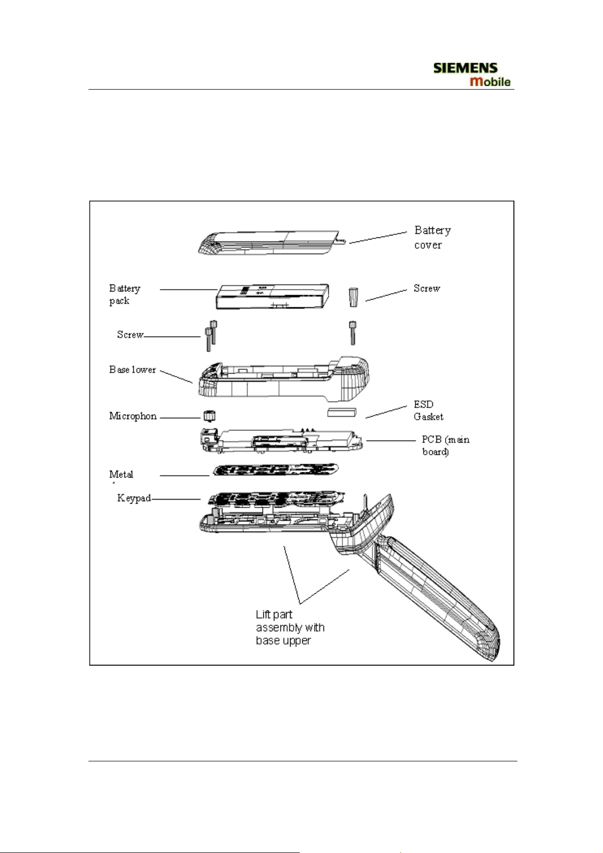
4.3 exploded view of CF62 Leopard
• Assembly in total with lift assembly
Copyright © Siemens Mobile
All rights reserved
Siemenes Shanghai Technical Support Center
13 of 42
SSMC MD CCQ
Internal Service Use Only
Page 14

SIEMENS
r
CF62 Level 2 Service Manual
• Lift part assembly
Display lens front
Lift cove
Lift cover
Hinge Vibra FPCB
Receiver
Magnet
LCD module
Lift frame
Display lens main A
Screw
LCD Cushion main
Display lens main B
Copyright © Siemens Mobile
All rights reserved
Siemenes Shanghai Technical Support Center
14 of 42
SSMC MD CCQ
Internal Service Use Only
Page 15

SIEMENS
CF62 Level 2 Service Manual
4.4 handset parts and defined service parts
Description Part-Nr
Battery pack CF62 V30145-K1310-X289
Repair
Lever
Level0
Qty.
1
Screw cover CF62 C39158-A120-C400 Level0 1
Battery cover CF62 C39158-A120-B501 Level0 1
Level1
Base upper assembly
CF62
C39158-A120-B201
1
Keypad CF62 C39158-A120-B600 Level1 1
Metal dome CF62 C39158-A120-C60 Level1 1
Base lower C39158-A120-B251
Level1
1
Screw 1,6x5,8 L55 C39158-A84-C94-1 Level1 1 For handset
Microphone CF62 C39254-Z6-F402 Level1 1
Level1
Lift cover assembly
CF62
C39158-A120-B1
1
Hinge CF62 C39158-A120-C350 Level1 1
Vibra CF62 V39197-F5009-F887 Level1 1
LCD module CF62 V39197-F5102-F402 Level1 1
FPCB CF62 Level1 1
Receiver assembly
CF62
LCD Cushion
main
C39158-A120-C40
Level1
Level1
1
1
Level1
Lift frame assembly C39158-A120-B21
1
Comments
( concerned sub-parts )
Base upper
(C39158-A120-B201)
Bumper
(C39158-A120-C330)
Triple band antenna
(C39158-A120-C80)
Antenna lid
(C39158-A120-B801),
Light loop
(C39158-A120-B211).
C39158-A120-B251
(C39158-A120-C42)
Lift cover
(C39158-A120-B1),
Lift cover adhesive
(C39158-A120-C37),
LCD Cushion front
(C39158-A120-C41),
Display lens front
(C39158-A120-B351)
(C39158-A120-C340).
C39158-A120-B321
C39158-A120-C342
Magnet
(V39190-F105-F751),
Lift frame
(C39158-A120-B21),
Display lens main A
(C39158-A120-B301)
(C39158-A120-C341)
(C39158-A120-C35).
Copyright © Siemens Mobile
All rights reserved
Siemenes Shanghai Technical Support Center
15 of 42
SSMC MD CCQ
Internal Service Use Only
Page 16

SIEMENS
CF62 Level 2 Service Manual
Level1
Display lens main B C39158-A120-B321
Screw 1,6x4,5 CF62 C39158-A120-C90
Level1
PCB (Main board) Level2 1
4.5 PCB top-side
1
6
C39158-A120-B321
(C39158-A120-C342)
(C39158-A120-C36)
Only for Lift part
assembly
4.6 PCB bottom-side
Copyright © Siemens Mobile
All rights reserved
Siemenes Shanghai Technical Support Center
16 of 42
SSMC MD CCQ
Internal Service Use Only
Page 17

SIEMENS
CF62 Level 2 Service Manual
5 Disassembly of CF62 Leopard
ESD concept; the internal circuits will be more susceptible to ESD because of the use of
exchangeable housing. The constru ction of the intern al block must b e/is designed, in the b est
possible way, to protect the circuit against sparks.
The keypad and the metal dome must be c ompletely cl osed to preven t any occurre nce of an E SD
disruptive discharge.
The SIM contacts may be open, thus reachable for ESD contact discharge. This could lead to
damage or destruction of the IC pins.
It is a requirement for the service personnel to observe ESD protection rules while performing
servicing the CF62.
Disassembly tools:
Copyright © Siemens Mobile
All rights reserved
Siemenes Shanghai Technical Support Center
17 of 42
SSMC MD CCQ
Internal Service Use Only
Page 18

SIEMENS
CF62 Level 2 Service Manual
Step 1:
Step
2:
Front view of the CF62.
Step
3:
Release the battery cover by placing your thumb
in the top centre and press downwards.
Step
5:
Back View of the CF62.
Step
4:
Release the battery pack by pressing upwards
Step
6:
Release the screw cover.
Copyright © Siemens Mobile
All rights reserved
Siemenes Shanghai Technical Support Center
Remove the three Base lower screws in the corners
with the screwdriver.
18 of 42
SSMC MD CCQ
Internal Service Use Only
Page 19

SIEMENS
CF62 Level 2 Service Manual
Step 7:
Step 8:
The lower edge of the Base lower has now been
detached from the phone as shown.
Step
9:
Remove the Microphone from the Base upper
assembly.
Step
11:
Remove the Base lower by carefully lifting it up.
Note: Be careful not to break or bend the top
plastic pin.
Step
10:
Detach the FPCB-cable connector from the PCB
(Main board) Assembly.
Remove the PCB Assembly by holding it of both in the middle and lifting it straight up.
Copyright © Siemens Mobile
All rights reserved
Siemenes Shanghai Technical Support Center
19 of 42
SSMC MD CCQ
Internal Service Use Only
Page 20

SIEMENS
CF62 Level 2 Service Manual
Step 12:Detach the PCB Assembly:
A:
B:
Remove the Keypad from the PCB (main board)
with the tweezers.
C:
Fully disassembled the PCB Assembly.
Step 13:
Remove the Metal dome from the PCB (main
board) with the tweezers.
Step 14:
To separate the Lift part assembly from the Base
upper assembly, push the hinge catch inwards
with a pair of special driver.
Copyright © Siemens Mobile
All rights reserved
Siemenes Shanghai Technical Support Center
Lift part assembly and Base upper assembly can be
seen after disassembled.
20 of 42
SSMC MD CCQ
Internal Service Use Only
Page 21

SIEMENS
CF62 Level 2 Service Manual
Step 15:Detach the Lift part assembly:
A:
B:
Remove the Display lens main B from the Lift
part assembly by using the driver.
C:
Remove the two screws from the Lift part
assembly by using the screwdriver.
E:
Lift part assembly and Display lens main B can be
seen after disassembled.
D:
To separate the Lift cover assembly from the Lift
part assembly.
F:
Remove the Hinge and the Vibra from the Lift
cover assembly.
Remove the LCD module from the Lift frame
assembly.
Copyright © Siemens Mobile
All rights reserved
Siemenes Shanghai Technical Support Center
21 of 42
SSMC MD CCQ
Internal Service Use Only
Page 22

SIEMENS
CF62 Level 2 Service Manual
G:
H:
Remove the FPCB-cable from the LCD module
by using the tweezers.
I:
Remove the LCD Cushion main from the Lift
frame assembly.
Step
16:
Remove the Receiver assembly from the Lift
frame assembly.
J:
Fully disassembled the Lift part assembly.
Fully disassembled CF62
Copyright © Siemens Mobile
All rights reserved
Siemenes Shanghai Technical Support Center
22 of 42
SSMC MD CCQ
Internal Service Use Only
Page 23

SIEMENS
CF62 Level 2 Service Manual
6 Assembly of CF62 Leopard
Step 1:
For the reassembly of the CF62 Lift part assembly, reverse the disassembly procedures Step 14
from J to A. Reassembled Lift part assembly as shown. Set torque to 16 Ncm.
Step 2:
To fix the Lift part assembly to the Base upper assembly, push the hinge catch inwards with a pair of
special driver.
Step 3:Reassemble the PCB Assembly
A:
B:
Take a PCB (Main board) and detach the protection
Take a new Metal dome.
foil from the new Metal dome with the tweezers.
Take care its two hole (marked with arrows)
position.
Copyright © Siemens Mobile
All rights reserved
Siemenes Shanghai Technical Support Center
23 of 42
SSMC MD CCQ
Internal Service Use Only
Page 24

SIEMENS
CF62 Level 2 Service Manual
C:
Press the Metal dome to ensure it is properly
glued on the PCB (main board), then prepare a
new Keypad.
E:
D:
Place the new Keypad in the assembled Base upper
assembly with the glue surface upwards, Detach the
protection foil from the new Keypad with the
tweezers.
F:
Place the assembled PCB (main board) onto the
assembled Base upper assembly with the
Keypad through the three pins(marked with
arrows), which align the PCB on the correct
position.
Remove the PCB Assembly by holding it alongside
the center and lifting it straight up, Press the Keypad
to make it glued properly.
Step 4:
Place the PCB Assembly onto the Base upper assembly. The three pins (marked with arrows) align the
PCB Assembly in its correct place.
Copyright © Siemens Mobile
All rights reserved
Siemenes Shanghai Technical Support Center
24 of 42
SSMC MD CCQ
Internal Service Use Only
Page 25

SIEMENS
CF62 Level 2 Service Manual
Step 5:
Step 6:
Step 7:
Push the FPCB-cable connector downwards until locked in the junction.
Take a new microphone and mount it in its place of the Base lower.
Step 8:
Put the Base lower assembly into the top of the
Base upper assembly and align the Base lower
assembly to the Base upper assembly. Check
that the Base lower assembly is ok and all the
components are in their places.
Place the three screws in the holes tightly then install
screw cover.
Copyright © Siemens Mobile
All rights reserved
Siemenes Shanghai Technical Support Center
25 of 42
SSMC MD CCQ
Internal Service Use Only
Page 26

SIEMENS
CF62 Level 2 Service Manual
Step 9:
Put the battery into the Base lower as shown.
Step 11:
Step 10:
Slide the Battery cover upwards until the cover
locked.
Unfold the Lift part press ON/OFF key as shown.
Copyright © Siemens Mobile
All rights reserved
Siemenes Shanghai Technical Support Center
26 of 42
SSMC MD CCQ
Internal Service Use Only
Page 27

SIEMENS
CF62 Level 2 Service Manual
7 Mobile Software Programming
7.1 Introduction
The common mobile software available is divided into language groups. However, this
software does not contain the specific settings, such as ringing tones, greeting text, short
dial list etc., required by the operator(s) or service provider(s). Therefore, it is not
uncommon to have some menu item(s) differ in different variants or are not visible at all.
These settings are stored in different memory area of the mobile and will be activated
depending on the customer specific model or variant of the phone by a separate test step
during the production process.
Due to this separation of common mobile software and customer specific initialization, it
is possible to fulfill the demands of the market requiring customization and flexibility. As
a consequence the software programming process in the LSO is divided into two different
steps as followed:
- Software update to actual version and appropriate language group
- Programming of customer specific initialization. Include mapping and FFS.
FIGURE 7.1 CF62 SERIES SOFTWARE PROGRAMMING SETUP
Copyright © Siemens Mobile
All rights reserved
Siemenes Shanghai Technical Support Center
27 of 42
SSMC MD CCQ
Internal Service Use Only
Page 28

SIEMENS
CF62 Level 2 Service Manual
7.2 Mobile Software Updating
The software of the mobile, CF62 series, is loaded from a PC directly. Hardware
interconnection between the mobile and the PC is shown in Figure 7.1
Because of the new type of external connector used in L55 (Slim-Lumberg type) an additional
adaptor cable between mobile and boot adaptor is required if the “black boot adaptor” is used.
Table 7.1 listed all the hardware requirements
If you use the battery dummy, make sure that the power supply voltage is correctly adjusted.
Description Part No.
Bootadapter 2000 incl. AC-Adapter, serial
cable and mobile connection cable
IBM Compatible PC – Pentium -
TABLE 7.1 EQUIPMENT LIST FOR SOFTWARE PROGRAMMING.
L36880-N9241-A200
Copyright © Siemens Mobile
All rights reserved
Siemenes Shanghai Technical Support Center
28 of 42
SSMC MD CCQ
Internal Service Use Only
Page 29

SIEMENS
CF62 Level 2 Service Manual
7.3 Flow chart for S/W upgrading
Copyright © Siemens Mobile
All rights reserved
Siemenes Shanghai Technical Support Center
29 of 42
SSMC MD CCQ
Internal Service Use Only
Page 30

SIEMENS
CF62 Level 2 Service Manual
8. Siemens Service Equipment User Manual
Introduction
Every LSO repairing Siemens handset must ensure that the quality standards are
observed. Siemens has developed an automatic testing system that will perform all
necessary measurements. This testing system is known as:
Siemens Mobile Service Equipment
Using this system vastly simplifies the repair of the phones and will make sure that:
1. All possible faults are detected
2. Sets, which pass the test, will be good enough to return to customer.
Starting from the P35 Series, Siemens will introduce a simpler and faster testing platform
for testing a repaired Siemens mobile phone. The testing platforms are either base on
R&S CMD 53/55 , CTS30/55 or CMU200GSM test set.
There is also test software under development for testing with the Wavetek 4201S / 44xx
and the 4107 GSM test set.
Copyright © Siemens Mobile
All rights reserved
Siemenes Shanghai Technical Support Center
30 of 42
SSMC MD CCQ
Internal Service Use Only
Page 31

SIEMENS
CF62 Level 2 Service Manual
9. JPICS (Java based Product Information Controlling
System)
Figure 1. JPICS log-in page
Overview
The following functions are available for the LSO:
General mobile information
•
• Generate PINCODE
• Generate SIMLOCK-UNLOCK-Code
• Print IMEI labels
• Lock, Unlock and Test the BF-Bus
Copyright © Siemens Mobile
All rights reserved
Siemenes Shanghai Technical Support Center
31 of 42
SSMC MD CCQ
Internal Service Use Only
Page 32

SIEMENS
CF62 Level 2 Service Manual
Overview
The following functions are available for the LSO:
• General mobile information
•
Generate PINCODE
• Generate SIMLOCK-UNLOCK-Code
• Print IMEI labels
• Lock, Unlock and Test the BF-Bus
The access to the JPICS server which is located in Kamp-Lintfort is protected by chip
card and in addition using secure socket layer (SSL) connection.
The JPICS server is only available for authorized users with a specially coded chip card.
These chip cards and the administration of the JPICS web server and the PICS
database-server can only be provided by the JPICS-TRUST-Center of the responsible
department in Kamp-Lintfort.
In case of any questions or requests concerning chip cards or administration of
the databases please ask your responsible Siemens Customer Care Manager.
Copyright © Siemens Mobile
All rights reserved
Siemenes Shanghai Technical Support Center
32 of 42
SSMC MD CCQ
Internal Service Use Only
Page 33

SIEMENS
CF62 Level 2 Service Manual
Installation overview
The following installation description assumes that a web browser is already installed.
JPICS is tested with the following browsers
1. Internet Explorer Version 5.5 and higher
2. Netscape Version 6 and higher
For further information regarding supported browsers, browser version and supported
operating systems, see the Sun FAQ's.
Here is a step by step instruction to install all the required components:
It is necessary to follow this order!
1. Card reader (Omnikey)
2. CardOS interface (Siemens)
3. JPICS Certificates
4. Java Plugin JVM/JRE (Sun)
5. Java additional components
Every user is responsible for a proper installation matching the license agreements.
For installation and further access you need the following:
1. The JPICS Installation-CD
2. A chip card. Chip cards can be ordered via your responsible Customer Care
Manager within Siemens.
3. A supported chip card reader (Smarty or Siemens B1) in order to access your chip
card.
Remark:
We recommend using Siemens B1 reader. Similar device to B1 is Cardman 9010.
In the module “Generate Codes“you can choose to generate:
- Master phone codes
- Simlock Unlock – Codes
Copyright © Siemens Mobile
All rights reserved
Siemenes Shanghai Technical Support Center
33 of 42
SSMC MD CCQ
Internal Service Use Only
Page 34

SIEMENS
CF62 Level 2 Service Manual
Master phone codes
The Master Phonecode is used to unlock blocked mobiles.
Master Phonecodes can only be supplied for mobiles which have been delivered in a
regular manner.
Figure 3. Master phone code page
Simlock Unlock - Code
The Simlock-Unlock-Codes can only be generated if the following conditions are given:
•
Mobile must have an active Simlock inside.
•
The user must be given the authorization to obtain Simlock Unlock- Codes for the
variant of the operator to which the mobile was delivered last time.
Copyright © Siemens Mobile
All rights reserved
Siemenes Shanghai Technical Support Center
34 of 42
SSMC MD CCQ
Internal Service Use Only
Page 35

SIEMENS
CF62 Level 2 Service Manual
Printing IMEI label
The module “Print IMEI label” offers the possibility to re-print IMEI labels for mobiles
again.
Copyright © Siemens Mobile
All rights reserved
Siemenes Shanghai Technical Support Center
35 of 42
SSMC MD CCQ
Internal Service Use Only
Page 36

SIEMENS
CF62 Level 2 Service Manual
You are able to print 1 label in just one step.
To prevent that misaligned labels are being printed, the setting "test printer = Yes" is
activated as default. After having printed a well-aligned test label you can switch setting
to "No" and print the correct label.
Hint:
For correct printing of IMEI labels you must have a
that fits for label printing. This printer has to be connected to local LPT1 printer port (also see
Installation of IMPRINT) and MUST feature a printing resolution of 300dpi.
Zebra – label printer
with special material
10. International Mobile Equipment Identity, IMEI
The mobile equipment is uniquely identified by the International Mobile Equipment Identity
IMEI, which consists of 15 digits. Type approval granted to a type of mobile is allocated 6
digits. The final assembly code is used to identify the final assembly plant and is assigned with
2 digits. 6 digits have been allocated for the equipment serial number for manufacturer and the
last digit is spare.
The part number for the CF62 is S30880-S6050-Axxx where the last 4 letters specify the
housing and software variant.
CF62 series IMEI label is accessible by removing the battery.
Re-use of IMEI label is possible by using a hair-dryer to remove the IMEI label.
On this IMEI label, Siemens has also includes the date code for production or service, which
conforms to the industrial standard DIN EN 60062. The date code comprises of 2 characters:
first character denotes the Year and the second character denotes the Month. For example, the
IMEI above show date code RD.
Year Date Code Month Date Code
2003 R
June 6
2004 S July 7
2005 T August 8
2006 U September 9
2007 V October O
2008 W November N
2009 X
December D
TABLE 8.1 DIN EN 60062 DATE CODE
Copyright © Siemens Mobile
All rights reserved
Siemenes Shanghai Technical Support Center
36 of 42
SSMC MD CCQ
Internal Service Use Only
Page 37

SIEMENS
CF62 Level 2 Service Manual
11.
General Testing Information
General Inf ormation
The technical instruction for testing GSM mobile phones is to ensure the best repair quality.
Validity
This procedure is to apply for all from Siemens AG authorized level 2 up to 2.5e workshops.
Procedure
All following checks and measurements have to be carried out in an ESD protected environment
and with ESD protected equipment/tools. For all activities the international ESD regulations have
to be considered.
Get delivery:
Ensure that every required information like fault description, customer data a.s.o. is
available.
Ensure that the packing of the defective items is according to packing requirements.
Ensure that there is a description available, how to unpack the defective items and what
to do with them.
Enter data into your database:
(Depends on your application system)
Ensure that every data, which is required for the IRIS-Reporting is available in your
database.
Ensure that there is a description available for the employees how to enter the data.
Incoming check and check after assembling:
!! Verify the customers fault description!!
After a successful verification pass the defective item to the responsible
troubleshooting group.
If the fault description can not be verified, perform additional tests to save time
and to improve repair quality.
- Switch on the device and enter PIN code if necessary unblock phone.
- Check the function of all
- Check the
- Check the ringer/loudspeaker acoustics by individual validation.
-
Perform a
display
GSM Test
for error in line and row, and for illumination.
keys.
as described on page 56.
Copyright © Siemens Mobile
All rights reserved
Siemenes Shanghai Technical Support Center
37 of 42
SSMC MD CCQ
Internal Service Use Only
Page 38

SIEMENS
CF62 Level 2 Service Manual
Check the charging capability:
Check internal resistance and capacity of the battery.
Check battery charging capability of the mobile phone.
Check charging capability of the power supply.
Check current consumption of the mobile phone in different mode.
Visual inspection:
Check the entire board for liquid damages.
Check the entire board for electrical damages.
Check the housing of the mobile phone for damages.
SW update:
Carry out a software update and data reset according to the master tables and
operator/customer requirements.
GSM Test:
Connect the mobile/board via internal antenna (antenna coupler) to a GSM
tester.
Use a Test SIM.
Skip GSM 900/GSM1800 or GSM1900 test cases if not performed by the mobile
phone.
Copyright © Siemens Mobile
All rights reserved
Siemenes Shanghai Technical Support Center
38 of 42
SSMC MD CCQ
Internal Service Use Only
Page 39

SIEMENS
CF62 Level 2 Service Manual
Copyright © Siemens Mobile
All rights reserved
Siemenes Shanghai Technical Support Center
39 of 42
SSMC MD CCQ
Internal Service Use Only
Page 40

SIEMENS
CF62 Level 2 Service Manual
Copyright © Siemens Mobile
All rights reserved
Siemenes Shanghai Technical Support Center
40 of 42
SSMC MD CCQ
Internal Service Use Only
Page 41

SIEMENS
CF62 Level 2 Service Manual
Final Inspection:
The final inspection contains:
1. A 100% network test (location update, and set up call).
2.
A random sample checks of:
- data reset (if required)
- optical appearance
- complete function
Check if PIN-Code is activated (delete the PIN-Code if necessary).
3.
Remark:
All sample checks must be documented.
Annex 1
Test SIM Card
There are two different “Test SIM Cards” in use:
Test SIM Card from the company “ORGA”
1.
Pin 1 number: 0000
PUK 1 : 12345678
Pin 2 number: 0000
PUK 2 : 23456789
Test SIM Card from the company “T-D1”
2.
Pin 1 number: 1234
PUK1 : 76543210
Pin 2 number: 5678
PUK 2 : 98765432
Copyright © Siemens Mobile
All rights reserved
Siemenes Shanghai Technical Support Center
41 of 42
SSMC MD CCQ
Internal Service Use Only
Page 42

SIEMENS
CF62 Level 2 Service Manual
Annex 2
Battery Date Code overview
Copyright © Siemens Mobile
All rights reserved
Siemenes Shanghai Technical Support Center
42 of 42
SSMC MD CCQ
Internal Service Use Only
 Loading...