

Page 1
Service Manual
Level 1-2
for
CF61
Release Date Department Notes to change
R 1.0 12.07.2006 BenQ Mobile CC S CES New document
Technical Documentation
TD_Repair_L1-L2_CF61_R1.0.pdf Page 1 of 42
Created by inservio GmbH for BenQ mobile GmbH & Co. OHG - Company Confidential2006©inservio
08/2006
Page 2

Table of Content
1 Key Feature................................................................................................................................3
2 Spare Part Overview of CF61 ...................................................................................................4
3 Disassembly of CF61................................................................................................................6
4 Assembly of CF61...................................................................................................................16
5 BenQ Service Equipment User Manual.................................................................................26
6 Setup of the Software..............................................................................................................27
7 Software basic settings ..........................................................................................................28
8 Software Download procedure...............................................................................................29
9 Download PPF (Handset configuration)................................................................................31
10 Backup and Restore of Wap and Network Setting...............................................................32
11 Backup and Restore of Media Center content......................................................................33
12 Unlock Tool..............................................................................................................................34
14 International Mobile Equipment Identity, IMEI......................................................................36
15 General Testing Information...................................................................................................37
Technical Documentation
TD_Repair_L1-L2_CF61_R1.0.pdf Page 2 of 42
Created by inservio GmbH for BenQ mobile GmbH & Co. OHG - Company Confidential2006©inservio
08/2006
Page 3
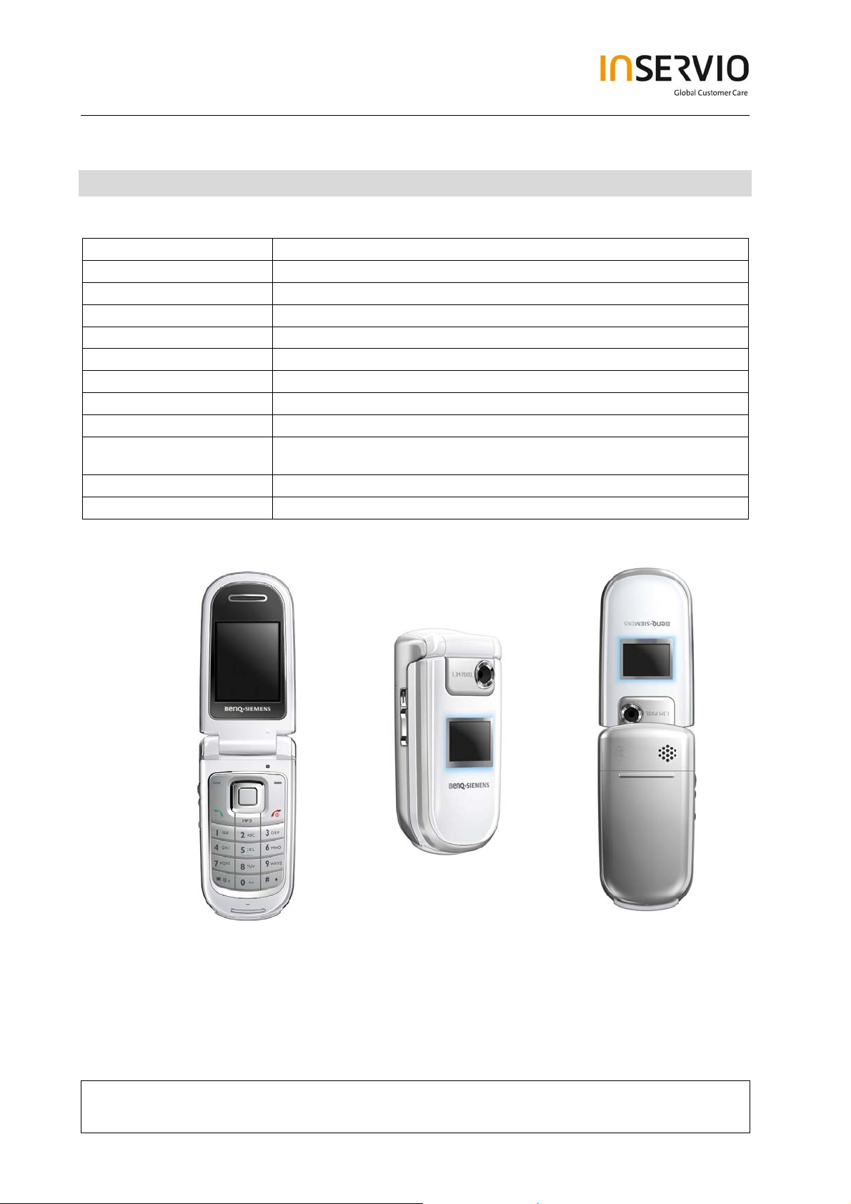
1 Key Feature
System
Battery
Stand – by Time
Talking Time
Antenna
Main Display
Sub - Display
Storage
Camera
Connectivity
Memory Slot
Processor
Technical Documentation
• Tri-Band GSM 900/1800/1900
• Li-Ion 750 mAh
• Up to 225h
• Up to 3 h
• Integrated
• 262, 144 TFT, 128x160 pixels, 1.8 inches
• 4,096 CSTN, 96x64 pixels
• 1.5 MB
• 1.3 megapixel, 4x linear digital zoom
• USB 1.1, Bluetooth: Object Push Profile, Object
Exchange, Handsfree Profile, Headset Profile
• MicroSD
• TI
08/2006
TD_Repair_L1-L2_CF61_R1.0.pdf Page 3 of 42
Created by inservio GmbH for BenQ mobile GmbH & Co. OHG - Company Confidential2006©inservio
Page 4
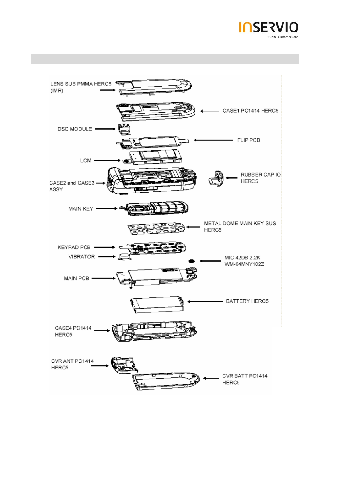
2 Spare Part Overview of CF61
Exploded View
Technical Documentation
TD_Repair_L1-L2_CF61_R1.0.pdf Page 4 of 42
Created by inservio GmbH for BenQ mobile GmbH & Co. OHG - Company Confidential2006©inservio
08/2006
Page 5
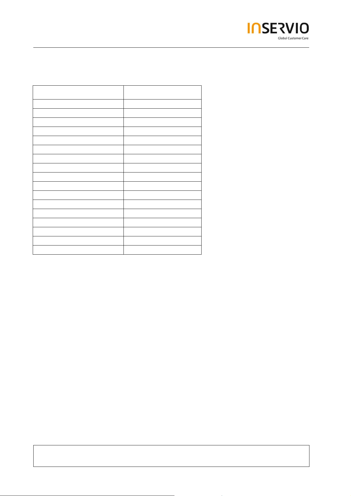
Order Number ( can be different by Variant specific parts)
Location E-commerce number:
BATTERY V30145-K1310-X457
MIC L50654-Z6-C146
VIBRATOR
METAL DOME MAIN KEY L50658-A220-A18-1
CVR BATTERY L50658-A220-A19-1
MAIN KEY L50658-A220-A2-1
RUBBER CAP I/O L50658-A220-A23-1
Flip PCB L50658-A220-A33-1
MAIN PCB S30880-Q3180-A1
KEYPAD PCB S30880-Q3183-A1
LCM L50658-A220-A24-1
DSC Module
Assy. CASE1 L50658-A220-A26-1
Assy. CASE2+3 L50658-A220-A27-1
Assy. CASE4 L50658-A220-A28-1
LENS SUB PMMA L50658-A220-A29-1
CVR ANT L50658-A220-A31-1
Technical Documentation
TD_Repair_L1-L2_CF61_R1.0.pdf Page 5 of 42
Created by inservio GmbH for BenQ mobile GmbH & Co. OHG - Company Confidential2006©inservio
08/2006
Page 6
3 Disassembly of CF61
All repairs as well as disassembling and assembling have to be carried out in an ESD
protected environment and with ESD protected equipment/tools. For all activities the
international ESD regulations have to be considered.
For more details please check information in c – market
https://market.benqmobile.com/SO/welcome.lookup.asp
There you can find the document “ESD Guideline”.
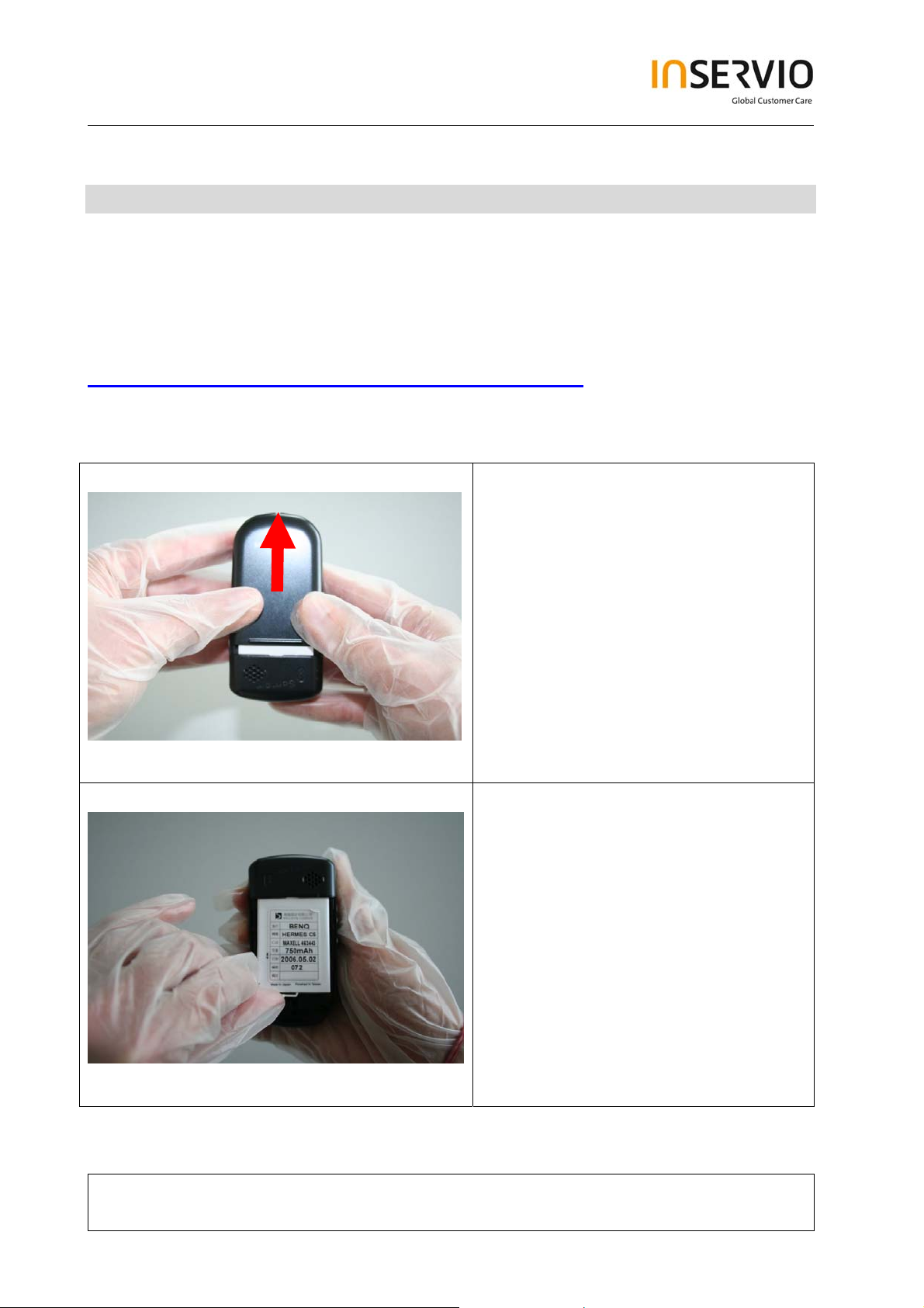
Step 1
Step 2
Remove Battery Cover.
Remove Battery.
Technical Documentation
TD_Repair_L1-L2_CF61_R1.0.pdf Page 6 of 42
Created by inservio GmbH for BenQ mobile GmbH & Co. OHG - Company Confidential2006©inservio
08/2006
Page 7
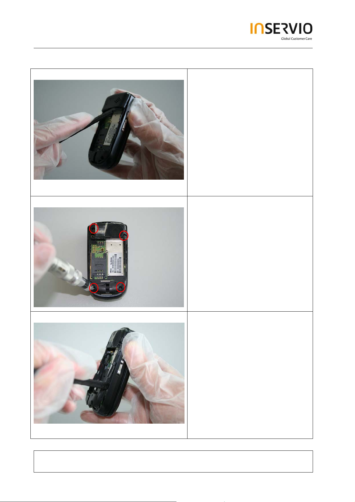
Step 3
Step 4
Remove Rear Cover by using the
Alternative Opening Tool carefully.
Remove screws by using the Torque
– Screwdriver.
T5+.
Step 5
Remove Lower Base Case Shell by
using the Alternative Opening Tool.
Technical Documentation
TD_Repair_L1-L2_CF61_R1.0.pdf Page 7 of 42
Created by inservio GmbH for BenQ mobile GmbH & Co. OHG - Company Confidential2006©inservio
08/2006
Page 8
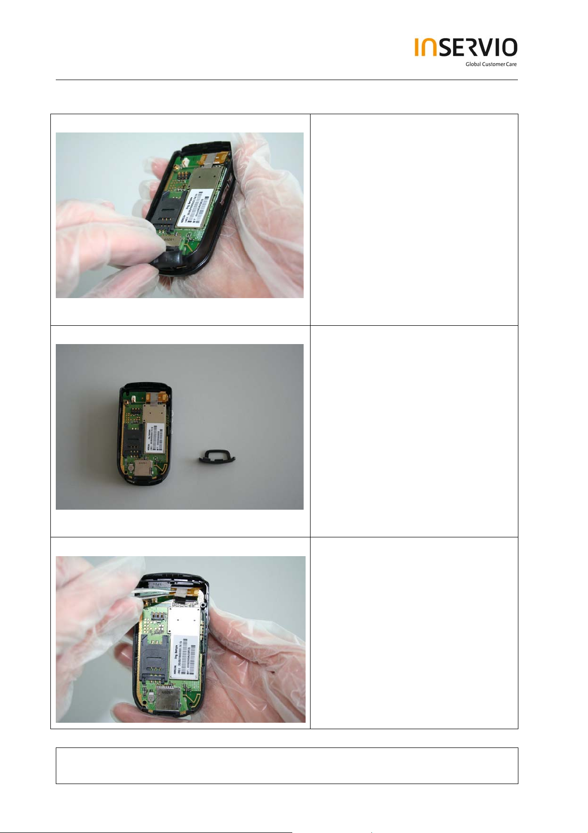
Step 6
Step 7
Remove MMI Slot Cap.
Step 8
Disconnect the Flex Cable by using
Tweezers.
Technical Documentation
TD_Repair_L1-L2_CF61_R1.0.pdf Page 8 of 42
Created by inservio GmbH for BenQ mobile GmbH & Co. OHG - Company Confidential2006©inservio
08/2006
Page 9
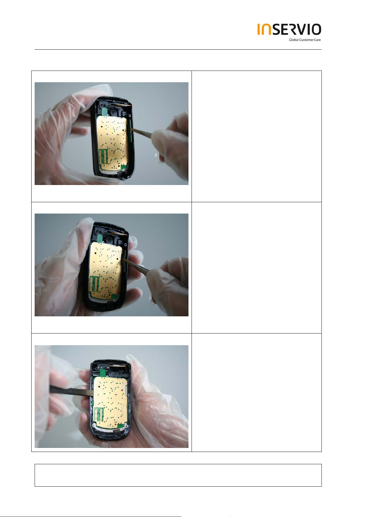
Step 9
Step 10
Remove the RF Control Board by
using the Alternative Opening Tool
carefully.
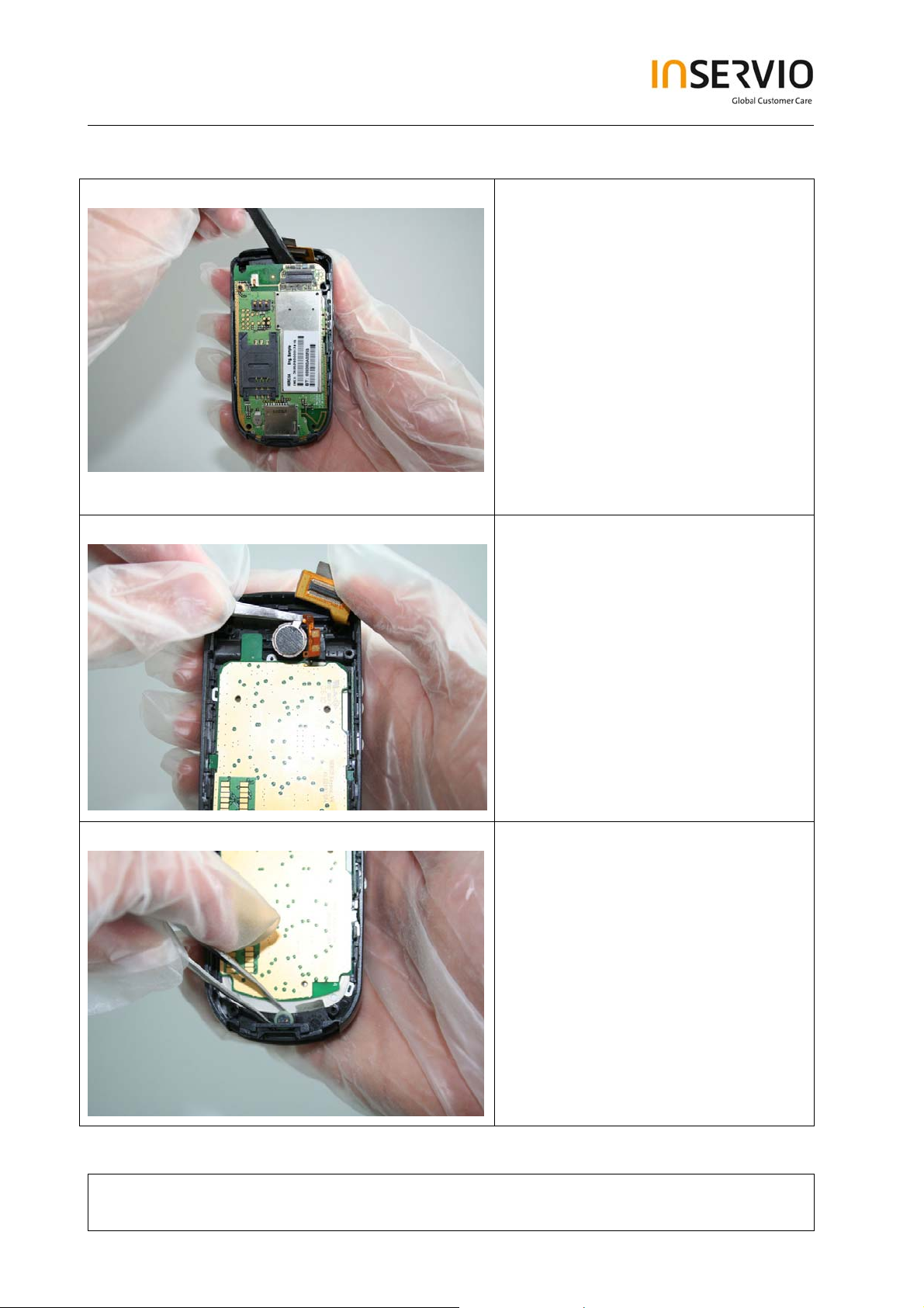
Remove the Vibra-Alert by using
Tweezers.
Step 11
Remove the Microphone by using
Tweezers. Take care of the spring
contact.
Technical Documentation
TD_Repair_L1-L2_CF61_R1.0.pdf Page 9 of 42
Created by inservio GmbH for BenQ mobile GmbH & Co. OHG - Company Confidential2006©inservio
08/2006
Page 10
Step 12
Step 13
Remove the Side Key PCB.
Remove the Side Key Left.
Step 14
Remove the Keypad PCB.
Technical Documentation
TD_Repair_L1-L2_CF61_R1.0.pdf Page 10 of 42
Created by inservio GmbH for BenQ mobile GmbH & Co. OHG - Company Confidential2006©inservio
08/2006
Page 11
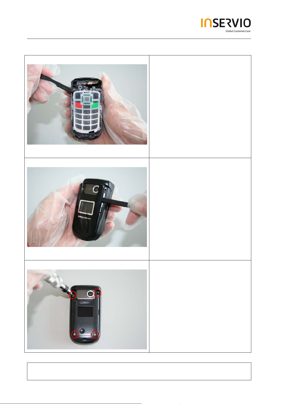
Step 15
Step 16
Remove the Keypad by using the
Alternative Opening Tool.
Remove Lower Lift Case Cap by
using the Alternative Opening Tool
carefully.
Step 17
Remove Screws by using the Torque
– Screwdriver. T5+.
Technical Documentation
TD_Repair_L1-L2_CF61_R1.0.pdf Page 11 of 42
Created by inservio GmbH for BenQ mobile GmbH & Co. OHG - Company Confidential2006©inservio
08/2006
Page 12
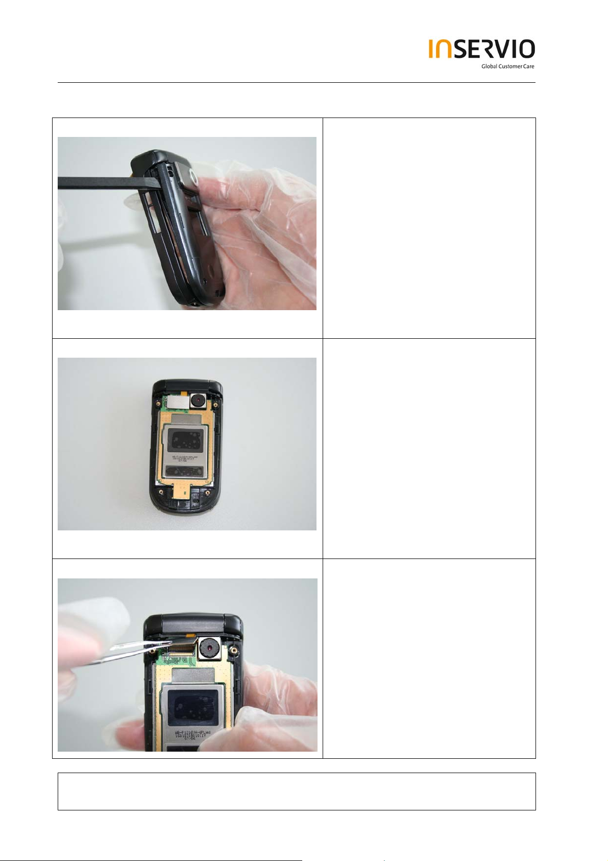
Step 18
Step 19
Remove Upper Lift Case Shell by
using the Alternative Opening Tool
carefully.
It is mandatory to place a Protection
Foil onto the Display to avoid
scratches.
Step 20
Disconnect the Flex Cable.
Technical Documentation
TD_Repair_L1-L2_CF61_R1.0.pdf Page 12 of 42
Created by inservio GmbH for BenQ mobile GmbH & Co. OHG - Company Confidential2006©inservio
08/2006
Page 13
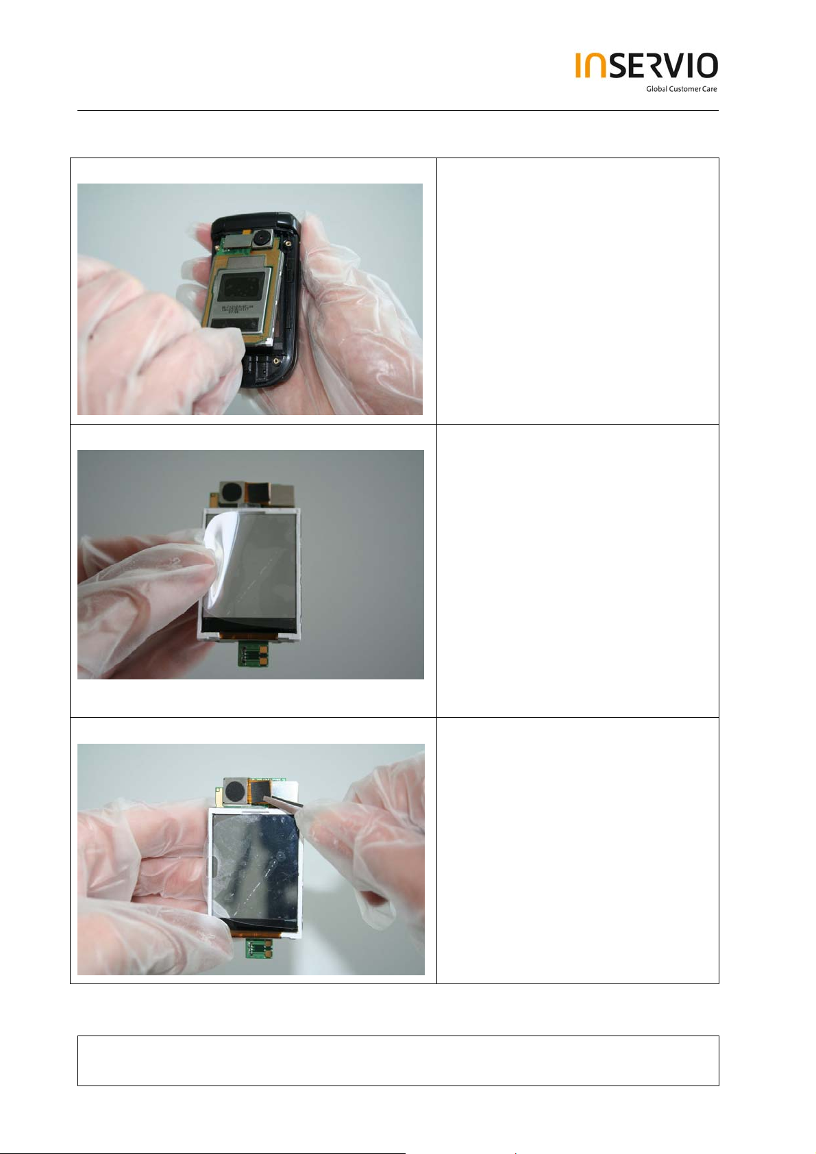
Step 21
Step 22
It is mandatory to place a Protection
Foil onto the Display to avoid
scratches.
Step 23
Technical Documentation
Remove the Camera Module by
disconnecting it from the socket.
08/2006
TD_Repair_L1-L2_CF61_R1.0.pdf Page 13 of 42
Created by inservio GmbH for BenQ mobile GmbH & Co. OHG - Company Confidential2006©inservio
Page 14

Step 24
Remove the Earpiece.
Step 25
Step 26
Use the Hinge Tool very carefully to
remove the Upper Base Case Shell
from the Lower Lift Case Shell.
Technical Documentation
TD_Repair_L1-L2_CF61_R1.0.pdf Page 14 of 42
Created by inservio GmbH for BenQ mobile GmbH & Co. OHG - Company Confidential2006©inservio
08/2006
Page 15

Step 27
Step 28
Take care of the Flex Cable, it easily
rips.
Remove the Flex Cable carefully.
Step 29
Remove the Hinge by using the
Hinge Tool.
Technical Documentation
TD_Repair_L1-L2_CF61_R1.0.pdf Page 15 of 42
Created by inservio GmbH for BenQ mobile GmbH & Co. OHG - Company Confidential2006©inservio
08/2006
Page 16

Step 30
Remove the Ringer by using
Tweezers carefully.
4 Assembly of CF61
Step 1
Step 2
Assemble the Ringer.
Assemble the Hinge.
Technical Documentation
TD_Repair_L1-L2_CF61_R1.0.pdf Page 16 of 42
Created by inservio GmbH for BenQ mobile GmbH & Co. OHG - Company Confidential2006©inservio
08/2006
Page 17

Step 3
Step 4
Assemble the Flex Cable. Take care
of it!
Insert the Flex Cable into the Lower
Lift Case Shell.
Step 5
Assemble the Lower Lift Case Shell
and the Upper Base Case Shell by
using the Hinge Tool.
Technical Documentation
TD_Repair_L1-L2_CF61_R1.0.pdf Page 17 of 42
Created by inservio GmbH for BenQ mobile GmbH & Co. OHG - Company Confidential2006©inservio
08/2006
Page 18

Step 6
Step 7
Assemble the Earpiece by using the
Tweezers.
Assemble the Camera Module by
connecting it with the socket.
Step 8
Remove Display Foil.
Technical Documentation
TD_Repair_L1-L2_CF61_R1.0.pdf Page 18 of 42
Created by inservio GmbH for BenQ mobile GmbH & Co. OHG - Company Confidential2006©inservio
08/2006
Page 19

Step 9
Step 10
Assemble the Display Module.
Connect the Flex Cable with the
socket.
Step 11
Remove Display Foil.
Technical Documentation
TD_Repair_L1-L2_CF61_R1.0.pdf Page 19 of 42
Created by inservio GmbH for BenQ mobile GmbH & Co. OHG - Company Confidential2006©inservio
08/2006
Page 20

Step 12
Assemble Upper Lift Case and Lower
Lift Case.
Step 13
Place screws by using the Torque –
Screwdriver T5+.
Step 14
Technical Documentation
Assemble the Lower Lift Case Cap.
08/2006
TD_Repair_L1-L2_CF61_R1.0.pdf Page 20 of 42
Created by inservio GmbH for BenQ mobile GmbH & Co. OHG - Company Confidential2006©inservio
Page 21

Step 15
Step 16
Assemble Keypad.
Assemble Keypad PCB.
Step 17
Assemble the Side Key Left by using
Tweezers.
Technical Documentation
TD_Repair_L1-L2_CF61_R1.0.pdf Page 21 of 42
Created by inservio GmbH for BenQ mobile GmbH & Co. OHG - Company Confidential2006©inservio
08/2006
Page 22

Step 18
Step 19
Assemble the Side Key PCB by
using Tweezers.
Assemble the Microphone by using
Tweezers.
Step 20
Assemble the Vibra-Alert by using
Tweezers.
Technical Documentation
TD_Repair_L1-L2_CF61_R1.0.pdf Page 22 of 42
Created by inservio GmbH for BenQ mobile GmbH & Co. OHG - Company Confidential2006©inservio
08/2006
Page 23

Step 21
Assemble the RF Control Board.
Step 22
Step 23
Connect the Flex Cable with the
socket.
Assemble the MMI Slot Cap.
Technical Documentation
TD_Repair_L1-L2_CF61_R1.0.pdf Page 23 of 42
Created by inservio GmbH for BenQ mobile GmbH & Co. OHG - Company Confidential2006©inservio
08/2006
Page 24

Step 24
Assemble the Lower Base Case
Shell.
Step 25
Step 26
Place screws by using the Torque –
Screwdriver T5+.
Assemble the Rear Cover.
Technical Documentation
TD_Repair_L1-L2_CF61_R1.0.pdf Page 24 of 42
Created by inservio GmbH for BenQ mobile GmbH & Co. OHG - Company Confidential2006©inservio
08/2006
Page 25

Step 27
Assemble Battery.
Step 28
Assemble Battery Cover.
Technical Documentation
TD_Repair_L1-L2_CF61_R1.0.pdf Page 25 of 42
Created by inservio GmbH for BenQ mobile GmbH & Co. OHG - Company Confidential2006©inservio
08/2006
Page 26

5 BenQ Service Equipment User Manual
Introduction
Every LSO repairing BenQ handset must ensure that the quality standards are
observed. BenQ has developed an automatic testing system that will perform all
necessary measurements. This testing system is known as:
BenQ Mobile Service Equipment
• For disassembling / assembling
Torque – Screwdriver
Part Number: F 30032 – P 228 – A1
Opening tool
(Case opening without destroying)
Part Number: F 30032 – P 38 – A1
Alternative Opening tool
Part Number: F30032 – P583 – A1
Tweezers
• For testing
All mobile phones have to be tested with the GRT – Software. The service partner
is responsible to ensure that all required hardware is available.
For additional Software and Hardware options as well as the supported GRT
equipment, please check the GRT User manual.
Technical Documentation
TD_Repair_L1-L2_CF61_R1.0.pdf Page 26 of 42
Created by inservio GmbH for BenQ mobile GmbH & Co. OHG - Company Confidential2006©inservio
08/2006
Page 27

6 Setup of the Software
Download of the required software:
Download the driver, the XCSD software mobile software (core-software and language files)
from the Technical Support Page:
https://market.benqmobile.com/so/welcome.lookup.asp
Installation of USB – Serial converter boot cable:
Start the “DataCableDrvInstaller.exe” file and follow the instructions of the installer.
Plug in the Data cable and follow the installation instructions to complete the process.
Check the Comport number of the data cable in the device manager.
(XCSD tool supports only Comport 1 to 10)
Technical Documentation
TD_Repair_L1-L2_CF61_R1.0.pdf Page 27 of 42
Created by inservio GmbH for BenQ mobile GmbH & Co. OHG - Company Confidential2006©inservio
08/2006
Page 28

Installation of XCSD tool:
Start “setup.exe” file and follow the instructions.
The installer creates a shortcut in the start menu bar. Start – Programs – XCSDTool_L1 BenQS
7 Software basic settings
Start the software (BenQS.exe). The XCSD tool will be shown on the screen
Select Model (for example see the screenshot below):
Select Com port (Setting – Com port):
Technical Documentation
TD_Repair_L1-L2_CF61_R1.0.pdf Page 28 of 42
Created by inservio GmbH for BenQ mobile GmbH & Co. OHG - Company Confidential2006©inservio
08/2006
Page 29

8 Software Download procedure
Select Download Option (View – Download):
Technical Documentation
TD_Repair_L1-L2_CF61_R1.0.pdf Page 29 of 42
Created by inservio GmbH for BenQ mobile GmbH & Co. OHG - Company Confidential2006©inservio
08/2006
Page 30

Select Program Code (example: E22 1 11710.mot) and
Language Pack (example E22 L 11711.mot)
Status bar colour scheme:
yellow waiting for update
blue update in progress
red error occurred
black Comport not
available
green Update successful
Connect mobile phone with data cable. Phone must be switched off. Click on “Start”
button and press the power on button on the handset to start the download. During
download process status bar shows the state of the process of P = Program code,
L = Language file and S = Set default (if activated). After successful SW download, the
status bar of the used Com port is changed to green.
Erase of customer data:
Select the “Power-off set default” option to erase all customer data of the phone during the
download process.
Click the “Set E2p” to erase the customer data without software update.
SW files naming rules:
Program Code E22111710
Language Pack E22L11711
E22 Project name
117 Program Code
L Language Pack
117 Version 1.17
10/11 Program Code ID
Technical Documentation
08/2006
TD_Repair_L1-L2_CF61_R1.0.pdf Page 30 of 42
Created by inservio GmbH for BenQ mobile GmbH & Co. OHG - Company Confidential2006©inservio
Page 31

9 Download PPF (Handset configuration)
Select write PPF option (View – Write PPF):
Select Database File (example: E22111710.bin) and
PPF File (example benq_m315_twn.ppf)
Connect mobile phone with data cable. Phone must be switched on. Click to “Write PPF”
button to start the process.
Confirmation about successful write of PPF appears after process is completed.
Don’t activate
Technical Documentation
TD_Repair_L1-L2_CF61_R1.0.pdf Page 31 of 42
Created by inservio GmbH for BenQ mobile GmbH & Co. OHG - Company Confidential2006©inservio
08/2006
Page 32

10 Backup and Restore of Wap and Network Setting
Select Back and Restore of Wap and Network Settings option
(View – Wap/Network Bkp/Restore):
Technical Documentation
TD_Repair_L1-L2_CF61_R1.0.pdf Page 32 of 42
Created by inservio GmbH for BenQ mobile GmbH & Co. OHG - Company Confidential2006©inservio
08/2006
Page 33

Select Database File (example: E22111710.bin) and
Setting File (create new txt file and rename it to ntk file for settings
backup)
Connect mobile phone with data cable. Phone must be switched off.
Click to “Backup” button to start the transfer the settings into the selected file.
Click to “Restore” button to start the transfer from selected file into handset.
11 Backup and Restore of Media Center content
Select Back and Restore of Media center (View – Media center Bkp/Restore):
Technical Documentation
TD_Repair_L1-L2_CF61_R1.0.pdf Page 33 of 42
Created by inservio GmbH for BenQ mobile GmbH & Co. OHG - Company Confidential2006©inservio
08/2006
Page 34

Select Media File (create new txt file and rename it to mmd file)
Connect mobile phone with data cable. Phone must be switched on.
Click to “Backup” button to start the transfer the settings into the selected file.
Click to “Restore” button to start the transfer from selected file into handset.
12 Unlock Tool
Select Unlock tool function (View – Unlock Tool):
Technical Documentation
08/2006
TD_Repair_L1-L2_CF61_R1.0.pdf Page 34 of 42
Created by inservio GmbH for BenQ mobile GmbH & Co. OHG - Company Confidential2006©inservio
Page 35

Select Database File (example: E22111710.bin)
Click to “Show PW” button to get the codes.
Unlock the codes in the mobile phone menu.
Click to “Hide PW” button to hide the codes.
Technical Documentation
TD_Repair_L1-L2_CF61_R1.0.pdf Page 35 of 42
Created by inservio GmbH for BenQ mobile GmbH & Co. OHG - Company Confidential2006©inservio
08/2006
Page 36

14 International Mobile Equipment Identity, IMEI
The mobile equipment is uniquely identified by the International Mobile Equipment
Identity, IMEI, which consists of 15 digits. Type approval granted to a type of mobile is
allocated 6 digits. The final assembly code is used to identify the final assembly plant
and is assigned with 2 digits. 6 digits have been allocated for the equipment serial
number for manufacturer and the last digit is spare.
CF61 series IMEI label is accessible by removing the battery.
Re – use of IMEI label is possible by using a hair – dryer to remove the IMEI label.
Date code is shown on IMEI label: Detailed description on how to read date code is
given in Annex 2.
To display the IMEI number, exit code and SW/HW version, key: * # 300 #
Code *#301# activates self diagnosis.
Technical Documentation
TD_Repair_L1-L2_CF61_R1.0.pdf Page 36 of 42
Created by inservio GmbH for BenQ mobile GmbH & Co. OHG - Company Confidential2006©inservio
08/2006
Page 37

15 General Testing Information
General Information
The technical instruction for testing GSM mobile phones is to ensure the best repair
quality.
Validity
This procedure is to apply for all from Siemens AG authorized level 2 up to 2.5e
workshops.
Procedure
All following checks and measurements have to be carried out in an ESD protected
environment and with ESD protected equipment/tools. For all activities the international
ESD regulations have to be considered.
Get delivery:
¾ Ensure that every required information like fault description, customer data a.s.o.
is available.
¾ Ensure that the packing of the defective items is according to packing
requirements.
¾ Ensure that there is a description available, how to unpack the defective items
and what to do with them.
Enter data into your database:
(Depends on your application system)
¾ Ensure that every data, which is required for the IRIS-Reporting is available in
your database.
¾ Ensure that there is a description available for the employees how to enter the
data.
Technical Documentation
TD_Repair_L1-L2_CF61_R1.0.pdf Page 37 of 42
Created by inservio GmbH for BenQ mobile GmbH & Co. OHG - Company Confidential2006©inservio
08/2006
Page 38

Incoming check and check after assembling:
!! Verify the customers fault description!!
¾ After a successful verification pass the defective item to the responsible
troubleshooting group.
¾ If the fault description can not be verified, perform additional tests to save time
and to improve repair quality.
- Switch on the device and enter PIN code if necessary unblock phone.
- Check the
- Check the display for error in
function of all keys including side keys.
line and row, and for illumination.
- Check the ringer/loudspeaker acoustics by individual validation.
- Perform a GSM Test as described on page 36.
Check the storage capability:
¾ Check internal resistance and capacity of the battery.
¾ Check battery charging capability of the mobile phone.
¾ Check charging capability of the power supply.
¾ Check current consumption of the mobile phone in different mode.
Visual inspection:
¾ Check the entire board for liquid damages.
¾ Check the entire board for electrical damages.
¾ Check the housing of the mobile phone for damages.
SW update:
¾ Carry out a software update and data reset according to the master tables and
operator/customer requirements.
Repairs:
The disassembling as well as the assembling of a mobile phone has to be
carried out by considering the rules mentioned in the dedicated manuals. If
special equipment is required the service partner has to use it and to ensure
the correct function of the tools.
If components and especially soldered components have to be replaced all
rules mentioned in dedicated manuals or additional information e.g. service
information have to be considered
Technical Documentation
TD_Repair_L1-L2_CF61_R1.0.pdf Page 38 of 42
Created by inservio GmbH for BenQ mobile GmbH & Co. OHG - Company Confidential2006©inservio
08/2006
Page 39

GSM Test:
With the availability of the GRT Test /Alignment software, this tool has to be used to
perform the outgoing test!
>Connect the mobile/board via internal antenna (antenna coupler) and external antenna
(car cradle/universal antenna clip) to a GSM tester
>Use a Test SIM
For Triple Band phones use a separate test case, if the test software allows only one
handover.
Skip the GSM Band test cases if not performed by the mobile phone
Example: 1. Test file Band 1 = GSM900 / Band 2 = GSM1800
2. Test file Band 1 = GSM1900
Internal Antenna
Test case Parameter Measurements Limits
1 Location Update • GSM Band 1
• BS Power = -55 dBm
• middle BCCH
2 Call from BS • low TCH
• highest PCL
• BS Power = -75 dBm
• middle BCCH
3 TX GSM Band 1 • low TCH
• highest PCL
• BS Power = -75 dBm
• middle BCCH
4 Handover to GSM Band 2
Including Handover
Check
5 TX GSM Band 2 • low TCH
6 Call release from BS
• highest PCL0
• BS Power = -75 dBm
• middle BCCH
• Display check • individual
check
• Ringer/Loudspeaker
check
• Frequency Error
• Phase Error RMS
• Phase Error Peak
• Average Power
• Power Time Template
• Frequency Error
• Phase Error RMS
• Phase Error Peak
• Average Power
• Power Time Template
• individual
check
• GSM Spec.
• GSM Spec.
Technical Documentation
08/2006
TD_Repair_L1-L2_CF61_R1.0.pdf Page 39 of 42
Created by inservio GmbH for BenQ mobile GmbH & Co. OHG - Company Confidential2006©inservio
Page 40

External Antenna
7 Call from MS • GSM900
• high TCH
• second highest PCL
• BS Power = -75 dBm
• middle BCCH
8 TX GSM Band 1 • high TCH
• second highest PCL
• BS Power = -75 dBm
• middle BCCH
9 RX GSM Band 1 • high TCH
• BS Power = -102 dBm
• 50 Frames
• middle BCCH
10 Handover to GSM Band 2
Including Handover
Check
11 TX GSM Band 2 • high TCH
12 RX GSM Band2 • high TCH
13 Call release from MS
• second highest PCL
• BS Power = -75 dBm
• middle BCCH
• BS Power = -102 dBm
• 50 Frames
• middle BCCH
• Keyboard check • individual
check
• Frequency Error
• Phase Error RMS
• Phase Error Peak
• Average Power
• Power Time Template
• RX Level
• RX Qual
• BER Class Ib
• BER Class II
• BER Erased Frames
• Frequency Error
• Phase Error RMS
• Phase Error Peak
• Average Power
• Power Time Template
• RX Level
• RX Qual
• BER Class Ib
• BER Class II
• BER Erased Frames
• GSM Spec.
• GSM Spec.
• GSM Spec.
• GSM Spec.
Final Inspection:
The final inspection contains:
1) A 100% network test (location update, and set up call).
2) Refer to point 3.3.
3) A random sample checks of:
- Data reset (if required)
- Optical appearance
- complete function
4) Check if PIN-Code is activated (delete the PIN-Code if necessary).
Basis is the international standard of DIN ISO 2859.
Use Normal Sample Plan Level II and the Quality Border 0,4 for LSO.
Remark: All sample checks must be documented.
Technical Documentation
08/2006
TD_Repair_L1-L2_CF61_R1.0.pdf Page 40 of 42
Created by inservio GmbH for BenQ mobile GmbH & Co. OHG - Company Confidential2006©inservio
Page 41

Annex 1
Test SIM Card
There are two different “Test SIM Cards” in use:
1) Test SIM Card from the company “ORGA”
Pin 1 number: 0000
PUK 1 : 12345678
Pin 2 number: 0000
PUK 2 : 23456789
2) Test SIM Card from the company “T-D1”
Pin 1 number: 1234
PUK : 76543210
Pin 2 number: 5678
PUK 2 : 98765432
Technical Documentation
TD_Repair_L1-L2_CF61_R1.0.pdf Page 41 of 42
Created by inservio GmbH for BenQ mobile GmbH & Co. OHG - Company Confidential2006©inservio
08/2006
Page 42

Annex 2
Device Date Code overview
GSN rule:
(ex: GS11500001TG0)
GS 1 9 5 00001 TG0
Big class Date Month Year S/N Factory
Based on the definition above, GSC55... below means 2005/05/12.
Technical Documentation
TD_Repair_L1-L2_CF61_R1.0.pdf Page 42 of 42
Created by inservio GmbH for BenQ mobile GmbH & Co. OHG - Company Confidential2006©inservio
08/2006
 Loading...