

Page 1

Operation and Installation Instructions
CERBERUS PYROTRONICS
Model LP-30
Remote Station Module
TM
Cerberus Division
Operation
The CERBERUS PYROTRONICSTM Model LP-30
Remote Station (Leased Line) module, is designed to
transmit Alarm and Trouble signals from a protected
property to a fire headquarters, central station, or
other similar supervised control center, via leased
telephone lines. It meets the requirements of NEMA
Standards and NFP A Standard No. 72C for remote
station protective signaling systems so that it may be
used with a CERBERUS PYROTRONICSTM Model
LLA-5 receiving unit or with any other annunciator
designed to these same two standards. Actuation of
the module is from an alarm output signal from any
type ZU Zone Module or type TS Two Stage module,
along with that from the main control panel.
The module contains solid state circuitry to supply 24
VDC power for the alarm signal and supervision of the
dedicated lines. The unit, which has built-in surge
protection, operates on the polarity reversal principle.
Under normal operating conditions the supervisory or
alarm signal current is held between 3mA and 9mA
DC. The total maximum load resistance of the leased
line circuit, including the receiving equipment, is 5K
ohms. Two input activation terminals are provided for
flexibility of programming. The LP-30 must be used
with an LLM-1.
The module also contains a manually operated
disconnect switch which prevents an alarm signal from
being transmitted over the leased lines when desired
or during system tests. Operation of the switch will
illuminate the yellow Disconnect LED and cause a
system trouble condition. The LED will remain illuminated during an alarm condition, and can be lamp
tested by operating the disconnect switch.
Installation
1. Mount the module to the horizontal mounting
brackets in the control enclosure.
2. Install the Model JA-5 (5 in long) bus connector
cable assembly between receptacle P2 of the
module and receptacle P1 of the module or
control panel immediately preceding it on the
bus.
Note: If the preceding module is on another row
in the enclosure, a JA-24 (24 in long) bus
connector cable assembly will be required.
3. Modules are to be bus-connected from right to
left. For two-row enclosures, the modules in the
lower row are to be connected from left to right.
Succeeding rows are to be alternately connected, right to left, left to right, etc.
4. If a module is the last module in the system,
install either a JS-30 (30 in long) or JS-64 (64 in
long) bus connector assembly from the unused
receptacle of the last module to terminal 41* of
the CP-35 control panel. This completes the
module supervision circuit.
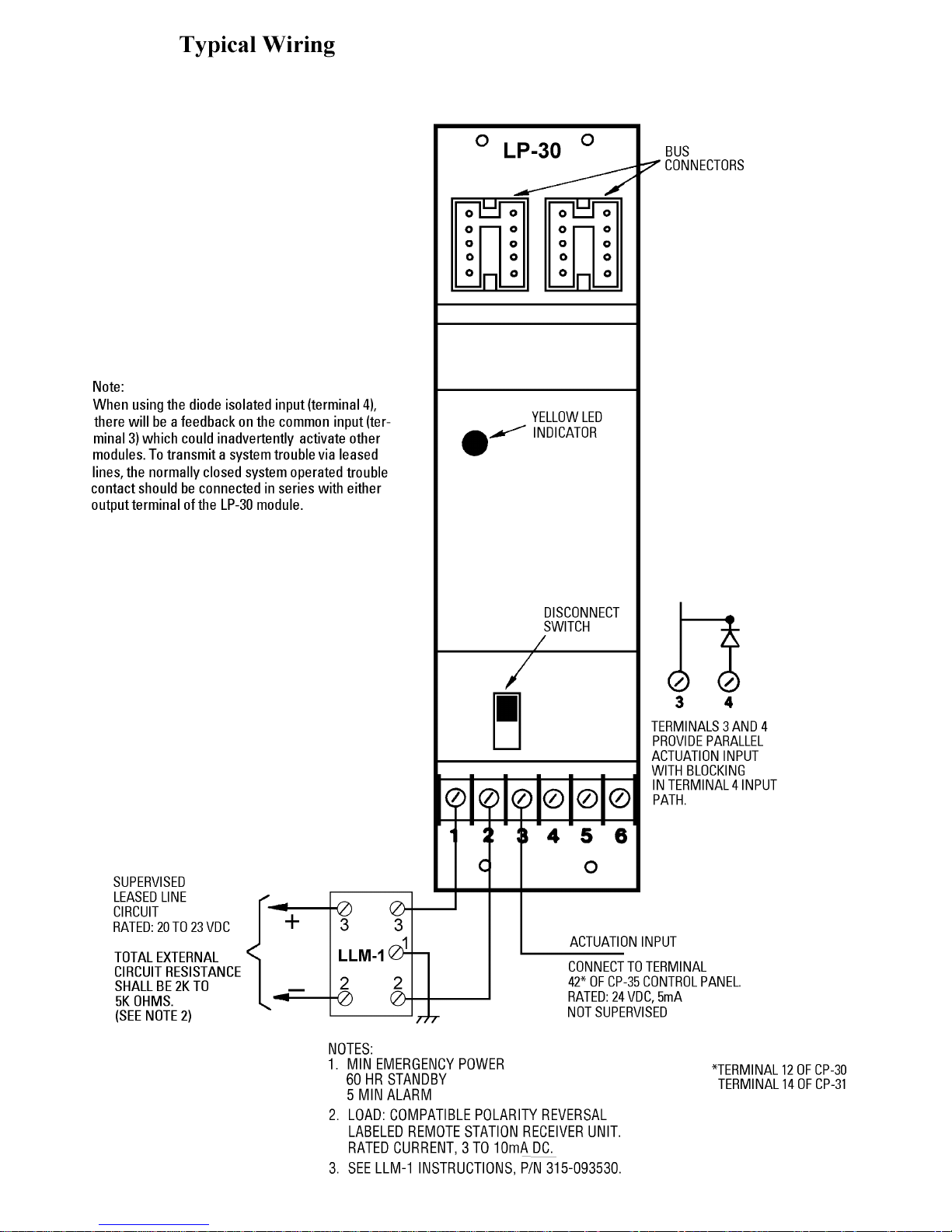
5. Wire terminals as shown in the Typical Wiring
illustration on the back of this sheet.
Troubleshooting
If a trouble condition is indicated in the LP-30, be sure
the disconnect switch is returned to Normal position.
*Terminal 17 of CP-30
Terminal 15 of CP-31
Siemens Building Technologies, Inc.
8 Fernwood Road
Florham Park, New Jersey 07932
P/N 315-021309-5
Siemens Building Technologies, Ltd.
50 East Pearce Street
Richmond Hill, Ontario L4B 1B7 CN
Page 2
P/N 315-021309-5
 Loading...