

Page 1

SiPass Entro / Bewator Entro
InfoPoint Terminal
Configuration Manual
Version 6.5
Building Technologies
Fire Safety & Security Products
Page 2

Liefermöglichkeiten und technische Änderungen vorbehalten.
Data and design subject to change without notice. / Supply subject to availability.
Sous réserve de modifications techniques et de la disponibilité.
Data och konstruktion kan komma att ändras utan föregående meddelande. / Leverans i mån av tillgång.
© 2009 Copyright by Siemens Building Technologies, Fire & Security Products GmbH & Co. oHG
Wir behalten uns alle Rechte an diesem Dokument und an dem in ihm dargestellten Gegenstand vor. Der Empfänger erkennt diese Rechte
an und wird dieses Dokument nicht ohne unsere vorgängige schriftliche Ermächtigung ganz oder teilweise Dritten zugänglich machen oder
außerhalb des Zweckes verwenden, zu dem es ihm übergeben worden ist.
We reserve all rights in this document and in the subject thereof. By acceptance of the document the recipient acknowledges these rights
and undertakes not to publish the document nor the subject thereof in full or in part, nor to make them available to any third party without our
prior express written authorization, nor to use it for any purpose other than for which it was delivered to him.
Nous nous réservons tous les droits sur ce document, ainsi que sur l'objet y figurant. La partie recevant ce document reconnaît ces droits et
elle s'engage à ne pas le rendre accessible à des tiers, même partiellement, sans notre autorisation écrite préalable et à ne pas l'employer
à des fins autres que celles pour lesquelles il lui a été remis.
Alla rättigheter till detta dokument och till föremålet för det förbehålles. Genom att acceptera dokumentet erkänner mottagaren dessa
rättigheter och förbinder sig att inte publicera dokumentet, eller föremålet därför, helt eller delvis, och att inte göra dem tillgängliga för tredje
part utan skriftligt tillstånd från oss, och att inte använda dem för något annat syfte än det för vilket de levererats.
Page 3

Contents (English)
1 Introduction .............................................................................................7
1.1 What is InfoPoint?.....................................................................................7
1.2 What equipment is needed? .....................................................................7
1.3 InfoPoint for Entro .....................................................................................8
2 The front panel ........................................................................................9
3 Installation .............................................................................................10
3.1 Mechanical installation............................................................................10
3.2 Electrical installation ...............................................................................10
3.2.1 Power supply...........................................................................................11
3.2.2 Installation...............................................................................................11
4 Set-up .....................................................................................................12
4.1 Factory settings – and to reset................................................................12
4.2 Restart of InfoPoint .................................................................................13
4.3 Updating firmware...................................................................................13
4.4 Change settings ......................................................................................13
4.5 Entering characters.................................................................................14
5 Technical data .......................................................................................15
Inhalt (Deutsch)
6 Einleitung...............................................................................................16
6.1 Was ist InfoPoint? ...................................................................................16
6.2 Erforderliche Ausrüstung ........................................................................16
6.3 InfoPoint für Entro ...................................................................................17
7 Frontseite...............................................................................................18
8 Installation .............................................................................................19
8.1 Mechanische Installation.........................................................................19
8.2 Elektrische Installation ............................................................................19
8.2.1 Stromversorgung.....................................................................................20
8.2.2 Anschluss................................................................................................20
9 Inbetriebnahme .....................................................................................21
9.1 Werkseitige Voreinstellungen und Reset................................................21
9.2 InfoPoint neu starten...............................................................................22
9.3 Softwareaktualisierung............................................................................22
9.4 Einstellungen ändern ..............................................................................22
10 Zeichen eingeben..................................................................................23
11 Technische Daten .................................................................................24
Building Technologies
Fire Safety & Security Products 06.2009
3
Page 4

Table des matières (Français)
12 Introduction ...........................................................................................25
12.1 Qu’est-ce que l’InfoPoint ?......................................................................25
12.2 Équipement requis ..................................................................................25
13 InfoPoint pour Entro .............................................................................26
14 Face avant..............................................................................................27
15 Installation .............................................................................................28
15.1 Installation mécanique ............................................................................28
15.2 Installation électrique ..............................................................................28
15.2.1 Alimentation.............................................................................................29
15.2.2 Installation ...............................................................................................29
16 Paramétrage ..........................................................................................30
16.1 Redémarrage d’InfoPoint ........................................................................31
16.2 Mise à jour du logiciel..............................................................................31
16.3 Modification des paramètres...................................................................31
16.4 Saisie de texte.........................................................................................32
17 Caractéristiques techniques................................................................33
Innehåll (Svenska)
18 Introduktion ...........................................................................................34
18.1 Vad är InfoPoint? ....................................................................................34
18.2 Vilken utrustning behövs?.......................................................................34
18.3 InfoPoint till Entro ....................................................................................35
19 Frontpanelen .........................................................................................36
20 Installation .............................................................................................37
20.1 Mekanisk installation ...............................................................................37
20.2 Elektrisk installation.................................................................................37
20.2.1 Strömförsörjning......................................................................................38
20.2.2 Inkoppling................................................................................................38
21 Driftsättning...........................................................................................39
21.1 Grundinställningar – och återställning till dessa......................................39
21.2 Omstart av InfoPoint ...............................................................................40
21.3 Uppdatering av programvara ..................................................................40
21.4 Ändra inställningar ..................................................................................40
21.5 Teckeninmatning.....................................................................................41
22 Tekniska data ........................................................................................42
4
Building Technologies
Fire Safety & Security Products 06.2009
Page 5

Building Technologies
Fire Safety & Security Products 06.2009
5
Page 6

Page 7

1 Introduction
This document is valid for both the Siemens and the Bewator branded products.
This manual describes how to install and set up the InfoPoint terminal. The product
is intended for use in reservation applications running within the Entro Access Control system. The unit is usually placed close to where it will reserve times e.g. a
conference room or a laundry room.
Note that the InfoPoint can exist in applications where ordinary PCs are also used
for similar functions.
1.1 What is InfoPoint?
The InfoPoint is a complete, intelligent TCP/IP-based terminal, which is similar to a
web browser in a PC.
Introduction
The terminal consists of a colour screen and navigation keys.
The InfoPoint has a proximity reader for identifying the user and has the ability to
send and receive information to and from a web server in much the same way as
you can with a newspaper web site.
Available functions and commands are software controlled by the host system.
1.2 What equipment is needed?
The InfoPoint is intended for integration within a system such as, for example, a
reservation system. InfoPoint requires a LAN connection and must have its own IPaddress. Furthermore the InfoPoint must be able to communicate with a web
server such as the Entro SR35i Segment Controller equipped with a CF8 memory
flash card.
Note that the InfoPoint can also operate with the older SR32i Segment Controller
but requires an upgrade of Entro software to version 4.7.
System Power supplies can be located centrally or locally to field hardware depending upon individual installation considerations.
The system requires the use of proximity cards or tags.
Building Technologies
Fire Safety & Security Products 06.2009
7
Page 8
Introduction
InfoPoint for Entro
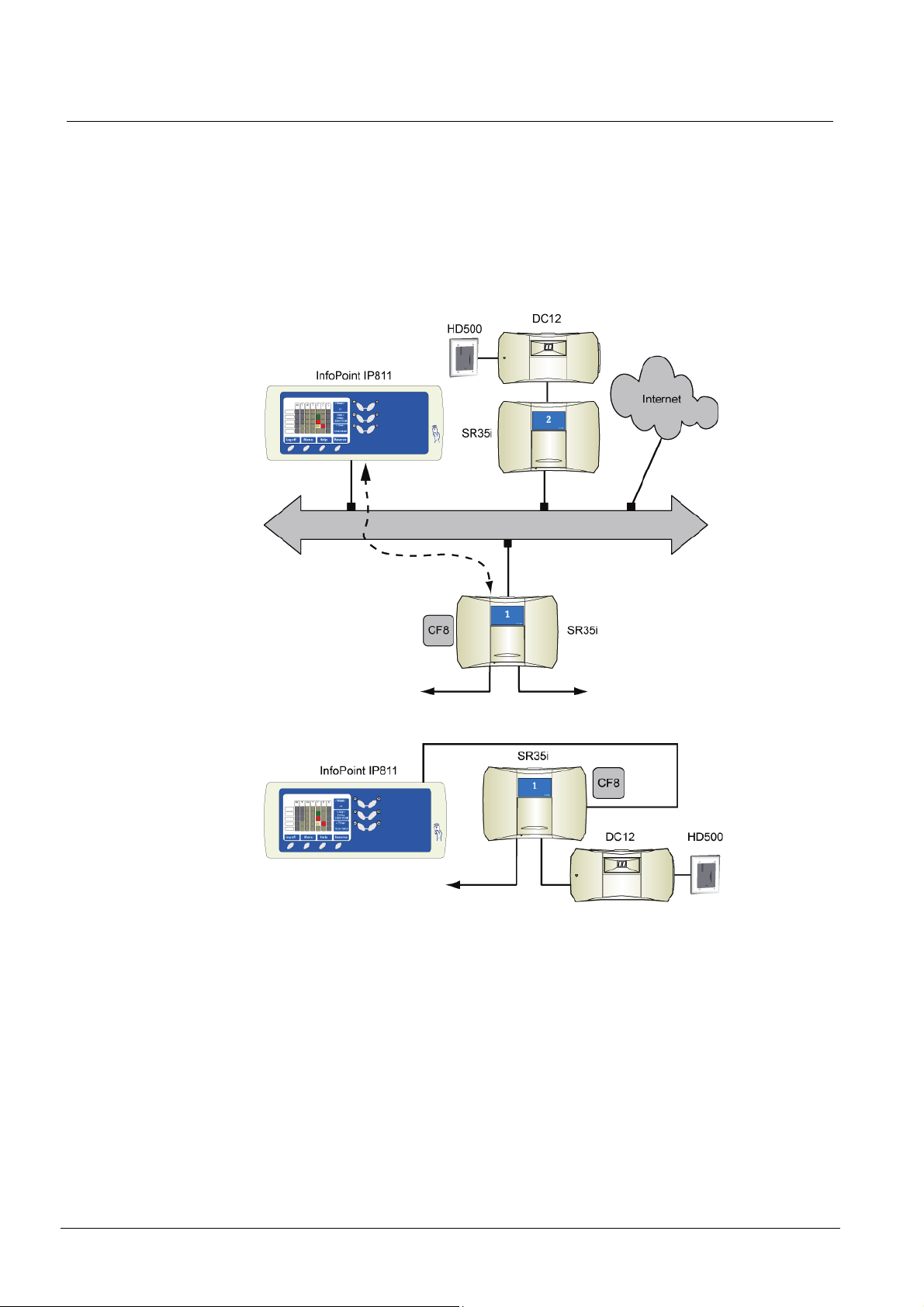
The SR35i Segment Controller acts as a web server for the InfoPoint. The SR35i
(or the older SR32i) must contain a CF8 memory flash card to store the information
(web pages), which would be displayed on the InfoPoint. It is important that the Entro system is set up with the appropriate information regarding reservation objects
and functions.
The InfoPoint can be used together with any element within the system, but in
practice it is most often used for the system component nearest to where it is
mounted.
Fig. 1 InfoPoint in Local Area Network and Internet
Fig. 2 InfoPoint directly connected to SR35i
In the above example the InfoPoint is used to reserve, cancel or control time intervals. The information is sent to the Access Control system which stores the time intervals etc. The user presents his/her card and can gain access to the reserved
door.
8
Building Technologies
Fire Safety & Security Products 06.2009
Page 9
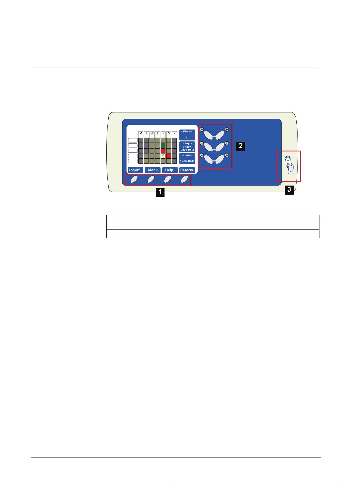
2 The front panel
The InfoPoint consists of a colour screen, navigation keys and an integrated software function for entering characters and digits (used for certain settings).
The InfoPoint has an integrated proximity reader.
The front panel
Fig. 3 Front panel
1. Function keys for commands
2. Keys for navigating
3. Embedded proximity reader
Building Technologies
Fire Safety & Security Products 06.2009
9
Page 10

Installation
3 Installation
The InfoPoint unit has all the connections at the rear and in normal circumstances
you should never need to open the unit.
3.1 Mechanical installation
The InfoPoint can be either surface-mounted or flush-mounted (in a flush-mounting
box BB7 ordered separately). Recommended height may be 140-150 cm. To cater
for disabled persons a suitable height is approximately 90-100 cm.
The InfoPoint is supplied with a wall mount kit as standard. It includes e.g. four
screws of type SecuFast Resitorx 3.5mm to fix the IP811. Please ensure you have
the necessary tools available.
Whether you intend to flush-mount it or not – remember that the cable hole must
allow sufficient clearance for the TCP/IP RJ45-connector. Alternatively the connector may be mounted on the free end of a Cat-5 cable.
It is important that the InfoPoint is mounted in such a way that light sources are not
reflected in the screen and the viewing angle is optimised for the user.
Mark the position and test mount the unit, but wait with the final mount, until you
have carried on with the further installation and set-up.
Remember that the terminal has an integrated proximity reader and considerations must be taken for electrical noise and disturbances.
3.2 Electrical installation
The terminal normally only has two connectors – one for the network and one for
the power supply.
The LAN connection (10BaseT) is made through a standard Cat-5 cable to a local
(or global) network with 10Mbit/s.
10
Building Technologies
Fire Safety & Security Products 06.2009
Page 11
3.2.1 Power supply
The power supply is connected via a special modular connector and cable assembly. This has a free end with connections for plus (+) and minus (-) for connection
to a suitable power source.
We recommend that the InfoPoint be powered from a battery-backed power supply
(in the access control system) via a junction box connected to the door controller.
If a local power supply is to be used, we recommend a PSU with filtered DC output
(12 or 24V DC).
Installation
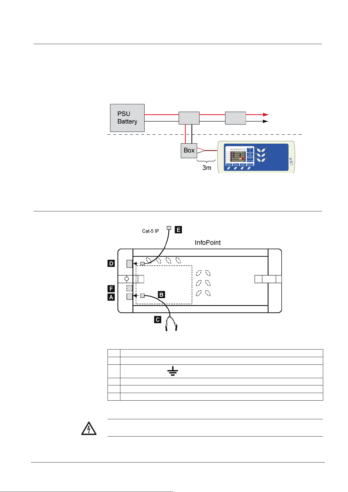
3.2.2 Installation
Fig. 4 Rear view of InfoPoint
A Power supply input (modular type connector).
B Supplied cable with modular type connector and with a free end. Length 3 metres.
C
Polarity
D Standard TCP/IP LAN connection, 10BaseT connector. Type RJ45.
E Standard Cat-5 cable for LAN connection
F Reserved for external unit.
+ = 24V, = 0V.
WARNING
The unit includes high-voltage driven components.
11
Building Technologies
Fire Safety & Security Products 06.2009
Page 12

Set-up
4 Set-up
The InfoPoint has integrated software for browsing the reservation functions in the
Segment Controller. It needs only to be set-up with the IP-address for the SR35i
Segment Controller in order to gain access to these functions.
In addition, the factory settings listed in the table on the next page will be used by
default. However, these parameters must be decided together with the IT-manager
and must be coordinated with the overall host computer network.
If there is a DHCP server (Dynamic Host Configuration Protocol) available in the
network, the InfoPoint networking parameters (such as IP address, Netmask and
Gateway) could be configured automatically. (This requires that the parameter
DHCP be set to YES).
4.1 Factory settings – and to reset
The first time you power up the InfoPoint, it has some factory set parameters according to the table below. To edit any of these - see Change settings.
To reset the factory settings:
1. Disconnect the power supply – or restart.
2. Press and hold the marked button (see figure). Hold it down until you hear
three beeps. z
3. Using the minus button furthest down, go down to the Factory settings and
press YES.
4. A warning message is displayed and you have to choose whether to proceed
(YES) - or not (NO).
Factory settings:
DHCP (NO or YES) ÆNO
- DHCP NO Æ Own IP address: 10.1.200.200 For InfoPoint
- DHCP NO Æ Netmask: 255.255.255.0 For InfoPoint
- DHCP NO Æ Gateway: 10.1.200.1 For InfoPoint
DNS Server 1 0.0.0.0 Name Server
DNS Server 2 0.0.0.0 Name Server
Server IP-address 10.1.200.101 IP-address for SR35i. Do not
Server Path /infopoint/ Search path to the CF8 memory
Start page index.iml Start page SR35i
DynDNS Server members.dyndns.org DHCP function
DynDNS Username <empty> DHCP function
DynDNS Password <empty> DHCP function
DynDNS Hostname <empty> DHCP function
enter a dot after the last digit!
If using names instead, the IP for
the DNS above must be set.
card of the SR35i.
12
Building Technologies
Fire Safety & Security Products 06.2009
Page 13

4.2 Restart of InfoPoint
If you need to restart the InfoPoint you do this by simultaneously pressing the three
keys shown in the figure (compare to Ctrl Alt Del in a PC).
Note that no parameters are changed – only a restart takes place in the same way
as you connect the power.
4.3 Updating firmware
If the Entro system offers a new firmware version for the InfoPoint you can
download this (from the SR35i) with a special command. The file is stored on the
CF8 card and the InfoPoint will check if it is a recent version. (If it is older it will not
be downloaded).
Remember that all address settings (such as IP, Server IP, Netmask etc) must be
correct in order for the download to take place. If Reservation has been working
before, the settings should of course be correct.
Set-up
You start the download by restarting (see above) and then press and hold down
the key furthest to the right. z
A message will be shown when downloading starts.
4.4 Change settings
If any parameters need to be changed (e g the IP-address) – proceed as follows:
1. Disconnect the power supply – or reboot and hold the marked button (see figure) to the right until you hear three beeps. z
2. Actual settings are displayed on the screen. There are two pages with settings
and you will see the next one by pressing “Next Page”.
3. Edit necessary changes accordingly.
4. Save by pressing the function button Save and Exit (or abort by pressing
Cancel). z
13
Building Technologies
Fire Safety & Security Products 06.2009
Page 14
Set-up
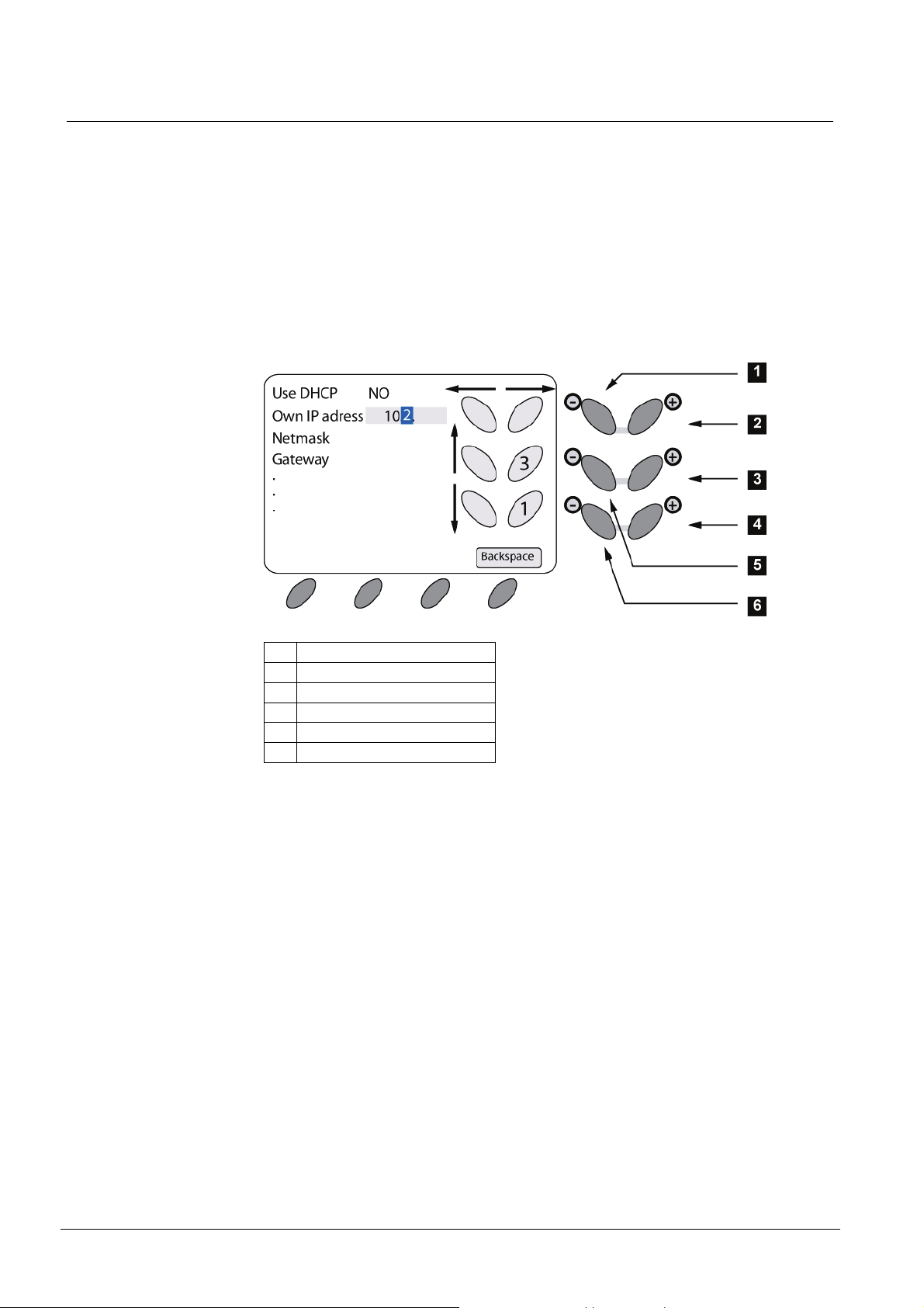
4.5 Entering characters
Several parameters allow/require that both digits and letters can be entered when
setting up the InfoPoint. The buttons to the right of the screen are used for navigating the cursor as well as choosing the character.
The “minus” buttons furthest to the left navigate up/down amongst the parameters
and the top “plus/minus” buttons move the cursor left/right. The “Backspace” button
erases one character and moves the cursor left.
When the cursor is in the correct position the “plus” buttons to the right are used for
scrolling through the character set. The current character is shown in the cursor
while the character before/after is displayed in the button symbols on the screen.
By moving the cursor right or left the character has been confirmed.
1. Move cursor left
2. Move cursor right
3. Choose next character
4. Choose previous character
5. Parameter up
6. Parameter down
The illustration shows how “2” is the current character and “1” or “3” can be selected with the “plus” buttons to the right.
14
Building Technologies
Fire Safety & Security Products 06.2009
Page 15

5 Technical data
Power supply: 12 – 35 V DC/AC
Power consumption: 350 mA 24V DC
Interface Standard TCP/IP LAN connection, 10BaseT
Keypad: 10 function keys
Screen: Colour screen with resolution 400 x 240 and 256
Lifetime background illumination: Approx. 10 years (at 3 hours use per day)
Temperature range: +5°C – + 40°C
Dimension - InfoPoint: 154 x 350 x 52 mm (HxWxD)
Dimension – Flush mounting box (outer dimen-
sion frame included):
Dimension – Cut-out hole for flush-mount (min): 140 x 354 x 40 mm (HxWxD)
Technical data
connector. Type RJ45.
colours
211 x 388 x 43 mm (HxWxD)
15
Building Technologies
Fire Safety & Security Products 06.2009
Page 16

Einleitung
6 Einleitung
Dieses Dokument gilt für das Produkt mit den Wahrenzeichen Siemens und
Bewator.
In diesem Handbuch werden Installation und Inbetriebnahme des Buchungsterminals InfoPoint beschrieben. Das Modell ist für die Nutzung mit EntroBuchungssystemen ausgelegt. Die Einheit wird meist in der Nähe des zu verwaltenden Objekts positioniert, z.B. ein Konferenzraum oder ein Waschkeller.
Beachten Sie, dass InfoPoint ebenfalls in Anlagen eingebunden sein kann, deren
Funktionen auch über PCs bedient werden.
6.1 Was ist InfoPoint?
InfoPoint ist ein umfassendes intelligentes Terminal mit Netzwerkanschluss, dass
zu großen Teilen mit einem Webbrowser auf einem PC verglichen werden kann.
Das Terminal ist mit einem Farbdisplay und Navigationstasten ausgestattet.
Zum Lieferumfang von InfoPoint gehört in der Regel auch ein Kartenleser, mit
dessen Hilfe der Nutzer der Einheit identifiziert wird.
InfoPoint ist in der Lage, Information von einem Webserver zu empfangen bzw. an
einen Webserver zu senden (wie z.B. beim Online-Banking).
Die ausführbaren Funktionen und Befehle richten sich größtenteils nach dem übergeordneten System.
6.2 Erforderliche Ausrüstung
InfoPoint ist stets Teil eines größeren Systems (z.B. für Buchungen). InfoPoint erfordert einen Netzwerkanschluss und erhält bei der Einrichtung eine eigene IPAdresse. InfoPoint muss über eine Datenverbindung mit einem Webserver verfügen, wie etwa Entro-Segmentcontroller SR35i mit CF8-Speicherkarte.
Beachten Sie, dass InfoPoint auch mit früheren Segmentcontrollern vom Typ
SR32i arbeitet. Die Entro-Software muss jedoch mindestens in Version 4.7 vorliegen.
Je nach Art der Installation ist eine lokale oder zentrale Stromversorgung möglich.
Um die Anlage nutzen zu können, müssen ihre Anwender über berührungslose Zutrittskarten oder Schlüsselanhänger verfügen.
16
Building Technologies
Fire Safety & Security Products 06.2009
Page 17

6.3 InfoPoint für Entro
Als Webserver für InfoPoint fungiert ein Segmentcontroller vom Typ Entro SR35i
(oder ein älterer Segmentcontroller vom Typ SR32i). Der Segmentcontroller muss
mit einer CF8-Speicherkarte ausgerüstet sein. Auf dieser werden die Informationen
(Webseiten) gespeichert, die per InfoPoint angezeigt werden. Das Entro-System
wird zuerst mit Informationen zu verschiedenen Objekten und sonstigen Buchungsfunktionen programmiert.
InfoPoint lässt sich für beliebige Objekte einsetzen. In der Praxis erfolgt jedoch eine Nutzung für das Objekt, das der Montageposition am nächsten liegt.
Einleitung
Fig. 5 InfoPoint im Netzwerk und mit Internetanbindung
Fig. 6 InfoPoint-Direktverbindung mit einem Segmentcontroller
In den oben beschriebenen Fällen kann InfoPoint zur Buchung, Stornierung oder
Steuerung von Zeiträumen genutzt werden. Die Informationen werden zum Einlasssystem übertragen, das die Zeiten speichert usw. Der Anwender kann nun per
Karte und Kartenleser die gebuchte Tür passieren.
17
Building Technologies
Fire Safety & Security Products 06.2009
Page 18

Frontseite
7 Frontseite
InfoPoint besitzt ein Farbdisplay und mehrere Navigationstasten sowie eine integrierte Software zur Eingabe von Buchstaben und Zahlen (erforderlich für bestimmte Einstellungen).
InfoPoint ist darüber hinaus mit einem integrierten und verborgenen berührungslosen Kartenleser für die Zutrittskontrolle ausgestattet.
InfoPoint ist darüber hinaus mit einem integrierten und verborgenen berührungslosen Kartenleser für die Zutrittskontrolle ausgestattet.
Fig. 7 Frontseite
1. Funktionstasten zur Befehlseingabe
2. Navigationstasten
3. Integrierter Kartenleser
18
Building Technologies
Fire Safety & Security Products 06.2009
Page 19

8 Installation
InfoPoint stellt eine komplette Einheit dar, an deren Rückseite alle Anschlüsse vorgenommen werden. Die Einheit wird normalerweise nicht vom Benutzer geöffnet.
8.1 Mechanische Installation
Für InfoPoint ist eine Auf- oder Unterputzmontage möglich. (Letztere erfolgt im Unterputzgehäuse BB7, das separat bestellt wird.) InfoPoint wird mit einer Wandhalterung und Schrauben (SecuFast Resitorx 3,5 mm) ausgeliefert. Dafür benötigen
Sie entsprechendes Werkzeug.
Die Montagehöhe liegt in der Regel zwischen ca. 140 und 150 cm. Bei behindertengerechter Montage gelten 90-100 cm als geeignete Höhe.
Ob Auf- oder Unterputzmontage: Beachten Sie, dass die Kabelöffnung für die
Durchführung eines RJ45-Netzwerksteckers ausgelegt sein muss. Andernfalls
muss der Anschluss mit einem losen Cat-5-Kabel verbunden werden.
Installation
InfoPoint muss so positioniert werden, dass die umgebende Beleuchtung nicht reflektiert wird und der Betrachtungswinkel für den Anwender möglichst optimal ausfällt.
Kennzeichnen Sie die Position und nehmen Sie eine Probemontage vor. Warten
Sie mit der endgültigen Montage, bis Anschluss und Inbetriebnahme erfolgt sind.
Bedenken Sie, dass das Terminal über einen integrierten berührungslosen Leser
verfügt, der nicht durch starken umgebende Magnetfelder gestört werden darf.
8.2 Elektrische Installation
Das Terminal besitzt normalerweise nur zwei Anschlüsse: einen für das Netzwerk
und einen für die Stromversorgung.
Der Netzwerkanschluss (10BaseT) wird über ein standardmäßiges Cat-5-Kabel mit
einem lokalen (oder globalen) Netzwerk mit 10 Mbit/s hergestellt.
19
Building Technologies
Fire Safety & Security Products 06.2009
Page 20

Installation
8.2.1 Stromversorgung
Die Stromversorgung erfolgt über einen speziellen Modularanschluss, mit dem das
beiliegende Kabel verbunden wird. Er weist ein offenes Ende mit Plus- (+) und Minusleitern (-) auf, die mit einer geeigneten Spannungsquelle verbunden werden.
Es wird empfohlen, die Stromversorgung für InfoPoint über eine Batteriesicherung
im System und eine Anschlusseinheit vorzunehmen, die mit einer Türzentrale verbunden wird.
Kommt stattdessen ein Transformator zum Einsatz, empfehlen wir eine gefilterte
Stromversorgung mit 24 V GS.
8.2.2 Anschluss
Fig. 8 Rückansicht von InfoPoint
A Spannungseingang mit Modularanschluss
B Beiliegendes Kabel mit Modularanschluss und offenem Ende, Länge: 3 m
C
Polarität
D Standardmäßiger TCP/IP-Netzwerkanschluss, 10Base T-Anschluss, Typ RJ45
E Standardmäßiges Cat-5-Kabel zum Netzwerkanschluss
F Reserviert für externe Einheiten
WARNUNG
Die Einheit umfasst Komponenten, die mit Hochspannung betrieben werden.
+ = 24V, = 0V.
20
Building Technologies
Fire Safety & Security Products 06.2009
Page 21

9 Inbetriebnahme
InfoPoint ist denkbar einfach in Betrieb zu nehmen. Da die Einheit eine hoch entwickelte Software für Webfunktionen enthält, muss sie lediglich mit der IP-Adresse
für SR35i programmiert werden.
Ansonsten gelten die werkseitigen Voreinstellungen in der folgenden Tabelle. Eine
Änderung dieser Einstellungen ist nach Rücksprache mit dem IT-Verantwortlichen
und unter Berücksichtigung der Systemkonfiguration vorzunehmen.
Befindet sich im Netzwerk ein DHCP-Server (Dynamic Host Configuration Protocol), kann InfoPoint automatisch eine eigene IP-Adresse, eine Netzmaske und ein
Gateway zugewiesen werden (wenn der DHCP-Server aktiviert ist).
9.1 Werkseitige Voreinstellungen und Reset
Wenn Sie InfoPoint zum ersten Mal einschalten, ist er mit den werkseitigen Voreinstellungen laut unten stehender Tabelle konfiguriert. Wie Sie diese ändern, entnehmen Sie dem folgenden Abschnitt Einstellungen ändern.
Inbetriebnahme
Um einen Reset auf die werkseitigen Voreinstellungen vorzunehmen, gehen Sie
wie folgt vor:
1. Unterbrechen Sie die Stromversorgung oder führen Sie einen Neustart aus.
2. Halten Sie die markierte Taste gedrückt (siehe Abb.) und schalten Sie die
Stromversorgung ein. Nachdem drei kurze Signaltöne ausgegeben wurden,
können Sie die Taste loslassen. z
3. Rufen Sie mit der untersten Minustaste den Eintrag Factory settings auf und
drücken Sie auf YES.
4. Es erscheint ein Warnhinweis. Mit YES setzen Sie den Vorgang fort, mit NO
brechen Sie ihn ab.
Es gelten folgende werkseitige Voreinstellungen:
DHCP (NO oder YES) Æ NO
DHCP NO Æ Own IP-address: 10.1.200.200 Für InfoPoint
DHCP NO Æ Netmask: 255.255.255.0 Für InfoPoint
DHCP NO Æ Gateway: 10.1.200.1 Für InfoPoint
DNS Server 1 0.0.0.0 Nameserver
DNS Server 2 0.0.0.0 Nameserver
Server IP-adress 10.1.200.101 IP-Adresse für SR35i. Geben
Server Path Pfad zu den Dateien der CF8-
Start page /infopoint/ SR35i-Startseite
DynDNS Server index.iml DHCP-Funktion
DynDNS Username members.dyndns.org DHCP-Funktion
DynDNS Password <empty> DHCP-Funktion
DynDNS Hostname <empty> DHCP-Funktion
Sie nach der letzten Zahl keinen Punkt ein. Bei Verwendung
eines Nameservers muss die IPAdresse für den DNS-Server
anzugeben.
Speicherkarte für SR35i.
21
Building Technologies
Fire Safety & Security Products 06.2009
Page 22

Inbetriebnahme
9.2 InfoPoint neu starten
Um InfoPoint neu zu starten, halten Sie die drei Tasten auf der Abbildung gleichzeitig gedrückt (vgl. STRG+ALT+ENTF unter Windows).
Hinweis: Dabei werden keine Einstellungen geändert. Es erfolgt lediglich ein Neustart wie beim Unterbrechen der Stromversorgung.
9.3 Softwareaktualisierung
Wenn im Entro-System eine neue Softwareversion für InfoPoint verfügbar ist, laden Sie diese (von SR35i) über einen Befehl während des Starvorgangs. Die betreffende Datei befindet sich auf der CF8-Speicherkarte. InfoPoint überprüft zuerst,
ob es sich um eine neuere Version handelt. (Bei einer älteren Datei findet keine
Datenübertragung statt.)
Beachten Sie, dass alle Adresseinstellungen (IP-Adresse, Server-IP-Adresse,
Netzmaske usw.) korrekt sein müssen, damit eine Datenübertragung stattfinden
kann. Wenn zuvor Buchungen ausgeführt werden konnten, sollten diese Angaben
stimmen.
Um die Datenübertragung zu starten, halten Sie nach einem Neustart die auf der
Abbildung markierte Taste gedrückt. z
Beim Aufspielen einer neuen Software erscheint eine entsprechende Meldung.
9.4 Einstellungen ändern
Wenn eine Einstellung geändert werden muss (z.B. IP-Adressen), gehen Sie wie
folgt vor:
1. Unterbrechen Sie die Stromversorgung oder führen Sie einen Neustart aus.
Halten Sie dabei die auf der Abbildung markierte Taste gedrückt, bis drei
kurze Signaltöne ausgegeben werden. z
2. Nun erscheinen die aktuellen Einstellungen auf dem Display. Durch Drücken
auf ”Next page” können Sie die folgende Bildschirmseite aufrufen.
3. Nehmen Sie die gewünschten Änderungen vor.
4. Zum Speichern klicken Sie auf Save and Exit. (Zum Abbrechen klicken Sie
auf Cancel.) z
22
Building Technologies
Fire Safety & Security Products 06.2009
Page 23

10 Zeichen eingeben
Mehrere Parameter zur InfoPoint-Einstellung ermöglichen bzw. erfordern die Eingabe von Zahlen oder Buchstaben. Die Tasten rechts neben dem Display können
verwendet werden, um den Cursor zu bewegen oder Zeichen auszuwählen.
Mit den linken Minustasten bewegen Sie sich innerhalb der Parameter auf oder ab.
Mit den obersten Plus/Minus-Tasten wird der Cursor nach links oder rechts bewegt. Mit der Taste ”Backspace” löschen Sie ein Zeichen und bewegen den Cursor
dabei nach links.
Wenn sich der Cursor an der korrekten Position befindet, bewegen Sie sich mit
den Plustasten zur Rechten vor oder zurück durch die verfügbaren Zeichen. Das
aktuelle Zeichen erscheint im Cursor. Das Zeichen davor bzw. danach wird grafisch in den Tastensymbolen auf dem Display dargestellt. Durch Weiterbewegen
des Cursors nach rechts bestätigen Sie Ihre Auswahl.
Zeichen eingeben
1. Cursor nach links
2. Cursor nach rechts
3. Nächstes Zeichen
4. Vorheriges Zeichen
5. Parameter auf
6. Parameter ab
23
Building Technologies
Fire Safety & Security Products 06.2009
Page 24

Technische Daten
11 Technische Daten
Stromversorgung: 12-35 V GS/WS
Stromverbrauch: 350 mA, 24 V GS
Schnittstelle Standardmäßiger TCP/IP-Netzwerkanschluss,
Tasten: 10 Funktionstasten
Display: Farbdisplay mit einer Auflösung von 400 x 240
Lebensdauer der Hintergrundbeleuchtung: Ca. 10 Jahre (bei 3 h Nutzung pro Tag)
Temperaturbereich: +5°C bis +40°C
Abmessungen InfoPoint: 154 x 350 x 52 mm (H x B x T)
Abmessungen Unterputzgehäuse (Außenmaße
einschl. Deckrahmen):
Min. Abmessungen Unterputzöffnung: 140 x 354 x 40 mm (H x B x T)
10BaseT-Anschluss, Typ RJ45
Bildpunkten und 256 Farben
211 x 388 x 43 mm (H x B x T)
24
Building Technologies
Fire Safety & Security Products 06.2009
Page 25

12 Introduction
Ce document s’applique pour les gammes Siemens et Bewator.
Ce manuel décrit l’installation et le paramétrage du terminal InfoPoint. Le modèle
conçus pour les applications spécifiques de restriction du système de contrôle
d’accès Entro. L’unité s’installe généralement à proximité de l’endroit où du temps
doit être restreint, par ex. près d’une salle de conférence ou d’une buanderie.
Remarque : l’InfoPoint peut également faire partie d’applications où des PC classiques sont également utilisés pour les mêmes fonctions.
12.1 Qu’est-ce que l’InfoPoint ?
L’InfoPoint est un terminal complet et intelligent basé sur le protocole TCP/IP dont
la fonction est similaire à un navigateur web sur un PC.
Il se compose d’un écran couleur et de touches de navigation.
Introduction
L’InfoPoint est doté d’un lecteur de proximité permettant d’identifier l’utilisateur. Il
peut en outre envoyer et recevoir des informations à destination et en provenance
d’un serveur web, fonctionnant à peu près de la même manière que le site d’un
journal en ligne.
Les fonctions et commandes disponibles sont contrôlées par le logiciel du système
hôte.
12.2 Équipement requis
L’InfoPoint est conçu pour être intégré à un système, par exemple un système de
restrictions. Il nécessite une connexion LAN et doit posséder sa propre adresse
IP. De plus, L’InfoPoint doit pouvoir communiquer avec un serveur web tel que le
Entro SR35i Segment Controller équipé d’une carte Memory Flash CF8.
Remarque : l’InfoPoint peut également être contrôlé avec l’ancien SR32i Segment
Controller pour autant que le logiciel Entro soit mis à jour avec la version 4.7.
L’alimentation du système peut être centralisée ou localisée au niveau de
l’équipement en fonction des besoins spécifiques de chaque utilisateur.
Le système fonctionne à l’aide de cartes de proximité ou de badges.
25
Building Technologies
Fire Safety & Security Products 06.2009
Page 26

InfoPoint pour Entro
13 InfoPoint pour Entro
Le Entro SR35i Segment Controller agit comme un serveur web pour l’InfoPoint.
Le SR35i (ou l’ancien SR32i) doit contenir une carte mémoire flash CF8 pour enregistrer les informations (pages web) qui s’afficheront sur l’InfoPoint. Il est important de paramétrer le système Entro à l’aide d’informations adéquates à propos
des fonctions et éléments sur lesquels portent les restrictions.
L’InfoPoint peut être utilisé en association avec tout élément du système, mais en
pratique, il est plus souvent utilisé pour le composant du système à proximité duquel il est installé.
Fig. 9 InfoPoint avec réseau local (LAN) et Internet.
Fig. 10 InfoPoint directement connecté au SR35i
Dans l’exemple ci-dessus, l’InfoPoint est utilisé pour restreindre, annuler ou contrôler les intervalles de temps. L’information est envoyée au système de contrôle
d’accès qui enregistre les intervalles, etc. Pour avoir accès à la porte restreinte,
l’utilisateur doit présenter sa carte.
26
Building Technologies
Fire Safety & Security Products 06.2009
Page 27

14 Face avant
L’InfoPoint se compose d’un écran couleur, de touches de navigation et d’un logiciel intégré permettant la saisie de lettres et de chiffres (utilisés pour certains paramètres). L’IP811 possède un pavé numérique permettant la saisie de chiffres
pour la « restriction de temps flexible ».
L’InfoPoint possède un lecteur de proximité intégré.
Face avant
Fig. 11 Face avant
1. Touches fonctions de commande
2. Touches de navigation
3. Touches de navigation
27
Building Technologies
Fire Safety & Security Products 06.2009
Page 28

Installation
15 Installation
Toutes les connexions s’effectuent à l’arrière de l’unité InfoPoint qui, en temps
normal, ne doit jamais être ouverte.
15.1 Installation mécanique
L’Infopoint peut être encastré ou monté en saillie (commander séparément un boîtier BB7 pour le montage encastré). La hauteur d’installation recommandée est de
140 à 150 cm. Lorsque le lecteur doit être utilisé par des personnes en fauteuil roulant, ramener la hauteur à environ 90-100 cm.
L’InfoPoint est fourni en standard avec le kit de montage mural. Il comprend notamment quatre vis de type SecuFast Resitorx 3.5mm pour fixer le IP811. Préparer
préalablement l’outillage requis.
Quel que soit le type de montage choisi, prévoir un passage de câble suffisamment grand pour le connecteur TCP/IP RJ45. Le connecteur peut également être
fixé sur l’extrémité libre d’un câble Cat-5.
Installer l’InfoPoint de telle manière que la lumière ne se reflète pas dans l’écran et
que l’angle de vision soit optimal pour l’utilisateur.
Marquer la position et tester le montage de l’unité. Ne pas la fixer définitivement
tant que l’installation et le paramétrage ne sont pas terminés.
Attention : le terminal intègre un lecteur de proximité. Il convient donc de prendre
les mesures qui s’imposent pour éviter les parasites et les interférences électriques.
15.2 Installation électrique
En principe, le terminal ne possède que deux connecteurs : l’un pour le réseau et
l’autre pour l’alimentation électrique.
La connexion LAN (10BaseT) s’effectue via un câble Cat-5 standard vers un réseau local (ou global) de 10Mbit/s.
28
Building Technologies
Fire Safety & Security Products 06.2009
Page 29

15.2.1 Alimentation
Installation
L’alimentation électrique est branchée via un câble et un connecteur modulaire
spécial. Une des extrémités est libre avec raccords plus (+) et moins (-) pour
connexion à une alimentation appropriée.
Nous conseillons de prévoir une alimentation de secours par batterie (dans le système de contrôle d’accès) via un boîtier de jonction connecté au contrôleur
d’accès.
En cas d’utilisation d’une alimentation locale, nous recommandons un PSU avec
sortie CC filtrée (12 ou 24V CC).
15.2.2 Installation
Fig. 12 Face arrière de l’InfoPoint
A Entrée alimentation (connecteur type modulaire).
B Cpable fourni avec connecteur modulaire, une extrémité libre.
Longueur 3 mètres
C
Polarité
+ = 24V, = 0V.
D Connexion standard TCP/IP LAN, connecteur 10BaseT. Type RJ45
E Câble standard Cat-5 pour connexion LAN.
F Réservé pour unité extérieure.
ATTENTION
L’unité contient des éléments sous haute tension..
29
Building Technologies
Fire Safety & Security Products 06.2009
Page 30

Paramétrage
16 Paramétrage
L’InfoPoint intègre un logiciel permettant de naviguer dans les fonctions de restriction du Segment Controller. Pour avoir accès à ces fonctions, il suffit de le paramétrer avec l’adresse IP du Segment Controller SR35i.
Les paramètres d’usine repris dans le tableau (voir page suivante) sont utilisés par
défaut. Toutefois, ces paramètres doivent être déterminés avec le manager IT et
correspondre au réseau informatique global.
Lorsqu’un serveur DHCP (Dynamic Host Configuration Protocol) est disponible
dans le réseau, les paramètres de mise en réseau de l’InfoPoint (tels que l’adresse
IP, Netmask et Gateway) peuvent être configurés automatiquement. (Pour cela, le
paramètre DHCP doit être réglé sur YES).
Paramètres d’usine – réinitialisation
Lors de la première mise sous tension, l’InfoPoint contient des paramètres d’usine
(voir tableau ci-dessous). Pour modifier ces paramètres, voir la rubrique Modification des paramètres.
Pour rétablir les paramètres d’usine :
1. Débrancher l’alimentation – ou redémarrer.
2. Maintenir enfoncé le bouton marqué (voir illustration) jusqu’à entendre trois
bips. z
3. À l’aide du bouton « moins », sélectionner les paramètres d’usine (Factory
settings) et appuyer sur YES.
4. Un avertissement s’affiche. Choisir YES pour poursuivre et NON pour annu-
ler.
Réglages d’usine :
DHCP (NO or YES) ÆNO
- DHCP NO Æ Own IP address: 10.1.200.200 Pour InfoPoint
- DHCP NO Æ Netmask: 255.255.255.0 Pour InfoPoint
- DHCP NO Æ Gateway: 10.1.200.1 Pour InfoPoint
DNS Serveur 1 0.0.0.0 Nom du serveur
DNS Serveur 2 0.0.0.0 Nom du serveur
Adresse IP du serveur 10.1.200.101 Adresse IP du SR35i. Ne tapez
Chemin d’accès du serveur /infopoint/ Chercher le chemin d’accès à la
Écran d’accueil index.iml Écran d’accueil SR35i
Serveur DynDNS members.dyndns.org Fonction DHCP
Nom d’utilisateur DynDNS <empty> Fonction DHCP
Mot de passe DynDNS <empty> Fonction DHCP
Nom d’hôte DynDNS <empty> Fonction DHCP
pas un point après le dernier
chiffre!
Lorsque des noms sont utilisés,
paramétrer l’IP du DNS cidessus.
carte mémoire CF8 du SR35i.
30
Building Technologies
Fire Safety & Security Products 06.2009
Page 31

16.1 Redémarrage d’InfoPoint
Pour redémarrer l’InfoPoint, appuyer simultanément sur les trois touches illustrées
(comparable à la combinaison Ctrl-Alt-Del sur un PC).
Remarque : aucun paramètre n’est modifié. Le redémarrage s’effectue comme à la
mise sous tension de l’appareil.
16.2 Mise à jour du logiciel
Lorsqu’une nouvelle version du logiciel Entro est disponible pour l’InfoPoint, elle
peut être téléchargée (à partir du SR35i) à l’aide d’une commande spéciale. Le fichier est enregistré dans la carte CF8 et l’InfoPoint vérifie si la version est plus récente. (Si la version est plus ancienne, elle n’est pas téléchargée.)
Remarque : pour que le téléchargement puisse s’effectuer, il faut que tous les paramètres d’adressage (IP, IP serveur, Netmask, etc.) soient corrects. Si le logiciel
de restriction fonctionnait précédemment, c’est que les paramètres étaient corrects.
Paramétrage
Pour lancer le téléchargement, redémarrer (voir ci-dessus) et maintenir enfoncée
la touche située tout à fait à droite. z
Un message s’affiche pour indiquer le début du téléchargement.
16.3 Modification des paramètres
Pour modifier des paramètres (par ex. l’adresse IP), procéder comme suit :
1. Débrancher l’alimentation ou réinitialiser l’appareil en maintenant enfoncé le
bouton marqué (voir figure) situé à droite jusqu’à entendre trois bips.
z
2. Les paramètres actifs s’affichent à l’écran. Les paramètres sont répartis sur
deux écrans. Pour passer à l’écran suivant, appuyer sur « Next Page ».
3. Effectuer les modifications souhaitées.
4. Enregistrer en appuyant sur la touche fonction Save and Exit (ou annuler en
appuyant sur Cancel). z
31
Building Technologies
Fire Safety & Security Products 06.2009
Page 32

Paramétrage
16.4 Saisie de texte
Plusieurs paramètres permettent et requièrent l’introduction de chiffres et de lettres
lors du paramétrage de l’InfoPoint. Les boutons à droite de l’écran servent à déplacer le curseur et à sélectionner les caractères.
Les boutons « moins » tout à fait à gauche permettent de se déplacer de haut en
bas dans les paramètres ; les boutons « plus/moins » situés au-dessus font bouger
le curseur de gauche à droite. La touche « Retour » (back space) efface un caractère précédent et déplace le curseur vers la gauche.
Lorsque le curseur est à la bonne place, les boutons « plus » situés à droite permettent de faire défiler les caractères. Le caractère actif s’affiche dans le curseur
tandis que le caractère qui le précède et celui qui le suit s’affichent dans les boutons représentés à l’écran. Pour confirmer le caractère, déplacer le curseur vers la
gauche ou la droite.
1. Curseur vers la gauche
2. Curseur vers la droite
3. Caractère suivant
4. Caractère précédent
5. Monter
6. Descendre
L’illustration indique que le « 2 » est le caractère actif, et que le « 1 » et le « 3 »
peuvent être sélectionnés à l’aide des boutons « Plus » situés à droite.
32
Building Technologies
Fire Safety & Security Products 06.2009
Page 33

17 Caractéristiques techniques
Alimentation : 12 – 35 V CC/CA
Consommation électrique : 350 mA 24 V CC
Interface Connexion TCP/IP LAN standard, connecteur
Pavé numérique : 10 touches fonctions.
Écran : Écran couleur, résolution 400 x 240 et 256 cou-
Durabilité du rétroéclairage Environ 10 ans (à raison de 3 heures par jour)
Plage de température : +5°C – + 40°C
Dimensions- InfoPoint : 154 x 350 x 52 mm (hxlxp)
Dimensions – Boîtier d’encastrement (y compris
cadre extérieur) :
Dimensions – Découpe pour montage encastré
(min):
Caractéristiques techniques
10BaseT. Type RJ45
leurs
211 x 388 x 43 mm (hxlxp)
140 x 354 x 40 mm (hxlxp)
33
Building Technologies
Fire Safety & Security Products 06.2009
Page 34

Introduktion
18 Introduktion
Detta dokument gäller för både den Siemens- och den Bewatormärkta produkten.
Denna handbok beskriver hur man installerar och driftsätter InfoPoint bokningsterminal. Produkten är avsedd för användning i bokningssystem till Entro. Oftast placeras den i närheten av det objekt som den ska hantera – t ex ett konferensrum eller en tvättstuga.
Observera att InfoPoint samtidigt kan ingå i anläggningar där även ordinära PC
används för liknande funktion.
18.1 Vad är InfoPoint?
InfoPoint är en komplett intelligent, nätverksansluten terminal som i många delar
kan liknas vid en webbläsare i en PC dator.
I terminalen finns en färgskärm och knappar för navigering.
InfoPoint innehåller normalt även en kortläsare för att kunna identifiera den person
som vill använda enheten.
InfoPoint har en inbyggd funktion för att kunna ta emot och sända information
från/till en s k webbserver (jfr när du ”surfar” med din hemdator till din bank).
Vilka funktioner och kommandon som kan göras bestäms till största delen av det
överordnade systemet.
18.2 Vilken utrustning behövs?
InfoPoint ingår alltid i ett större system med t ex bokning. InfoPoint kräver nätverksanslutning och använder en egen s.k. IP-adress. InfoPoint måste kunna
kommunicera med en webbserver som t ex Entro undercentral SR35i med CF8
minneskort.
Notera att InfoPoint även fungerar med tidigare undercentral SR32i men kräver
uppdatering till Entro programversion 4.7.
Strömförsörjning kan göras lokalt eller centralt beroende på hur installationen utförs.
Anläggningen kräver att användarna har tillgång till s.k. beröringsfria passerkort eller brickor.
34
Building Technologies
Fire Safety & Security Products 06.2009
Page 35

18.3 InfoPoint till Entro
Som webbserver för InfoPoint fungerar en Entro SR35i undercentral (eller äldre
SR32i). Undercentralen måste innehålla ett CF8 minneskort som används för att
lagra informationen (webbsidorna) som visas på InfoPoint. Entro systemet programmeras också först med information om olika objekt och övriga bokningsfunktioner.
InfoPoint kan användas för valfritt objekt men i praktiken nyttjas den för det objekt
som finns i närheten (där den är monterad).
Introduktion
Fig. 13 InfoPoint i nätverk och med Internet
Fig. 14 InfoPoint direkt till undercentral
I ovanstående fall kan InfoPoint användas för att boka, avboka eller kontrollera tider. Informationen skickas till passersystemet som lagrar tider osv. Användaren
kan sedan använda sitt kort i kortläsaren och passera den bokade dörren.
35
Building Technologies
Fire Safety & Security Products 06.2009
Page 36

Frontpanelen
19 Frontpanelen
InfoPoint har en färgskärm och ett antal knappar för navigering samt en inbyggd
programvarufunktion för att ange bokstäver och siffror (som behövs för vissa inställningar).
InfoPoint har även en inbyggd, dold beröringsfri kortläsare för inloggning.
Fig. 15 Frontpanelen
1. Funktions knappar för kommandon
2. Knappar för att navigera
3. Inbyggd kortläsare
36
Building Technologies
Fire Safety & Security Products 06.2009
Page 37

20 Installation
InfoPoint består av en komplett enhet där anslutningar görs i kontakter på baksidan. Du ska normalt inte öppna enheten.
20.1 Mekanisk installation
InfoPoint kan monteras både utanpåliggande eller infällt (i infällnadslåda BB7 som
måste beställas separat). InfoPoint levereras med ett väggfäste och skruvar av typen SecuFast Resitorx 3.5mm. Du bör ha tillgång nödvändiga verktyg för dessa.
Monteringshöjden kan normalt vara ca 140 – 150 cm. Om den istället ska handikappanpassas kan 90-100 cm vara lämplig höjd.
Oavsett om du ska fälla in terminalen eller inte – tänk på att hålet för kabel bör tillåta att RJ45-kontakten för nätverk kan dras igenom. I annat fall måste kontakten
monteras/klämmas på en lös kat-5 kabel.
Installation
Det är viktigt att InfoPoint placeras, så att inte omkringliggande belysning reflekteras samt att betraktningsvinkeln för användaren blir så god som möjligt.
Märk ut placeringen och gör en provmontering, men vänta med den slutliga monteringen, för att kunna fortsätta med inkoppling och driftsättning.
Tänk på att terminalen har en inbyggd beröringsfri läsare som inte får störas av
omgivande starka magnetfält.
20.2 Elektrisk installation
Terminalen har normalt endast två anslutningar – en för nätverk och en för strömförsörjning.
Nätverksanslutningen (10BaseT) görs med en standard kat-5 kabel till ett lokalt (eller globalt) nätverk med 10Mbit/s.
37
Building Technologies
Fire Safety & Security Products 06.2009
Page 38

Installation
20.2.1 Strömförsörjning
Strömförsörjning görs via en speciell modularkontakt där medföljande kabel kan
anslutas. Den har en fri ände med ledningar för plus (+) och minus (-) som kopplas
till lämplig spänningskälla.
Rekommendationen är att InfoPoint strömförsörjs från en batteribackup i systemet
via en kopplingsbox som ansluts till en dörrcentral.
Om en transformator används istället, rekommenderar vi en filtrerad 24V DC.
20.2.2 Inkoppling
Fig. 16 Vy från baksidan av InfoPoint
A Spänningsingång i modularkontakt.
B Medlevererad kabel med modularkontakt samt fri ände.
Längd 3 meter.
C
Polaritet
D Standard TCP/IP nätverksanslutning, 10BaseT kontakt. Typ RJ45.
E Standard Kat-5 kabel för nätverksanslutning.
F Reserverat för externa enheter.
VARNING
Enheten innehåller komponenter som drivs med högspänning.
+ = 24V, = 0V.
38
Building Technologies
Fire Safety & Security Products 06.2009
Page 39

21 Driftsättning
InfoPoint är mycket enkel att driftsätta. Eftersom den innehåller en avancerad programvara för webbfunktioner, så behöver den endast programmeras med IPadressen till SR35i.
I övrigt så har den de leveransinställningar som framgår av tabellen nedan. Ändringar av dessa ska bestämmas i samråd med IT-ansvarig – och samstämma med
systemet i övrigt.
Om en s.k. DHCP-server (Dynamic Host Configuration Protocol) finns i nätverket,
så kan InfoPoint automatiskt tilldelas en egen IP-adress, Netmask och Gateway
(förutsatt att inställningen DHCP är YES).
21.1 Grundinställningar – och återställning till dessa
Första gången du spänningssätter InfoPoint, så har den ett antal leveransinställningar enligt tabellen nedan. För att ändra dessa läser du nästa avsnitt Ändra inställningar
Driftsättning
Du kan alltid återställa till leveransinställningar genom att göra så här:
1. Bryt spänningen eller gör en omstart.
2. Tryck och håll inne den markerade knappen (se figuren) och slå på spänning-
en. Håll in knappen tills tre korta toner hörs. z
3. Stega med nedersta minus knappen till Factory settings och tryck på YES.
4. Ett varningsmeddelande visas och du kan välja att fortsätta (YES) - eller att
avbryta (NO).
Följande leveransinställningar (Factory settings) gäller:
DHCP (NO or YES) ÆNO
- DHCP NO Æ Own IP address: 10.1.200.200 För InfoPoint
- DHCP NO Æ Netmask: 255.255.255.0 För InfoPoint
- DHCP NO Æ Gateway: 10.1.200.1 För InfoPoint
DNS Server 1 0.0.0.0 Namnserver
DNS Server 2 0.0.0.0 Namnserver
Server IP-adress 10.1.200.101 IP-adress till SR35i. Ange inte
Om namn istället anges måste IP till
DNS anges ovan.
Server Path /infopoint/ Sökväg till filer på SR35i:s CF8
Start page index.iml Startsidan på SR35i
DynDNS Server members.dyndns.org DHCP funktion
DynDNS Username <empty> DHCP funktion
DynDNS Password <empty> DHCP funktion
DynDNS Hostname <empty> DHCP funktion
någon punkt efter sista siffran!
minneskort
39
Building Technologies
Fire Safety & Security Products 06.2009
Page 40

Driftsättning
21.2 Omstart av InfoPoint
Om du behöver starta om InfoPoint så kan du göra detta genom att samtidigt hålla
inne tre knappar enligt figuren (jämför Ctrl Alt Del på en PC).
Notera att inga inställningar förändras – utan bara en omstart görs på samma sätt
som när du slår på spänningen.
21.3 Uppdatering av programvara
Om Entro systemet erbjuder en ny version av programvaran för InfoPoint, så kan
du hämta detta (från SR35i) med ett kommando vid uppstart. Filen finns lagrad på
CF8 kortet och InfoPoint kontrollerar först att det är en senare version. (Skulle filen
varav äldre sker ingen nedladdning).
Tänk på att alla adressinställningar (IP, Server IP, Netmask osv.) måste vara korrekta för att nedladdning ska kunna ske. Om bokning har fungerat tidigare så bör
dessa givetvis vara korrekta.
Du startar nedladdning genom att efter omstart hålla inne den markerade knappen
(se figuren). z
Ett meddelande visas när en ny programvara laddas.
21.4 Ändra inställningar
Om någon inställning skall ändras (t ex IP-adresser) – gör på följande sätt:
1. Bryt spänningen eller gör en omstart och håll inne den markerade knappen
(se figuren) tills tre korta toner hörs. z
2. Nu visas aktuella inställningar på bildskärmen. Det finns två olika sidor när du
kan se nästa genom att trycka på ”Next page”.
3. Utför önskade ändringar av inställningar.
4. Spara genom att trycka på Save and Exit (eller avbryt med Cancel).
z
40
Building Technologies
Fire Safety & Security Products 06.2009
Page 41

21.5 Teckeninmatning
Flera parametrar medger/kräver att såväl siffror som bokstäver kan anges vid inställning av InfoPoint. Knapparna till höger om skärmen kan användas både för
navigering av markör respektive val av tecken.
De vänstra minusknapparna används för att navigering upp/ner bland parametrarna och översta plus-/minusknapparna flyttar markören vänster/höger. Knappen
”Backspace” raderar ett tecken och flyttar markören åt vänster.
När markören står i rätt position används plusknapparna till höger för att stega
framåt eller bakåt i teckenuppsättningen. Aktuellt tecken visas i markören medan
tecknet före/efter visas grafiskt i knappsymbolerna på skärmen. Genom att flytta
markören bekräftas valet.
Driftsättning
1. Flytta markör vänster
2. Flytta markör höger
3. Stega till nästa tecken
4. Stega till föregående tecken
5. Parameter uppåt
6. Parameter nedåt
Bilden visar hur ”2” är aktuellt tecken och ”1” eller ”3” kan anges med plusknapparna till höger. Genom att sedan stega åt sidan så har tecknet valts.
41
Building Technologies
Fire Safety & Security Products 06.2009
Page 42

Tekniska data
22 Tekniska data
Strömförsörjning: 12 – 35 V DC/AC
Strömförbrukning: 350 mA 24V DC
Gränssnitt Standard TCP/IP nätverksanslutning, 10BaseT
Knappsats: 10 funktionstangenter
Skärm: Färgskärm med upplösningen 400 x 240 och 256
Drifttid bakgrundsbelysning: Ca 10 år (vid 3 timmars användning per dag)
Temperaturområde: +5°C – + 40°C
Mått - InfoPoint: 154 x 350 x 52 mm (HxBxD)
Mått - Infällnadslåda (yttermått inkl täckram): 211 x 388 x 43 mm (HxBxD)
Mått – Hål för infällnad (min): 140 x 354 x 40 mm (HxBxD)
kontakt. Typ RJ45
färger
42
Building Technologies
Fire Safety & Security Products 06.2009
Page 43

Page 44

Issued by
Siemens Building Technologies
Fire & Security Products GmbH & Co. oHG
D-76181 Karlsruhe
www.buildingtechnologies.siemens.com/
Document no. A24205-A335-N335
Edition 06.2009
© 2009 Copyright by
Siemens Building Technologies,
Fire & Security Products GmbH & Co. oHG
Data and design subject to change without notice.
Supply subject to availability.
 Loading...