

Page 1
RM 4
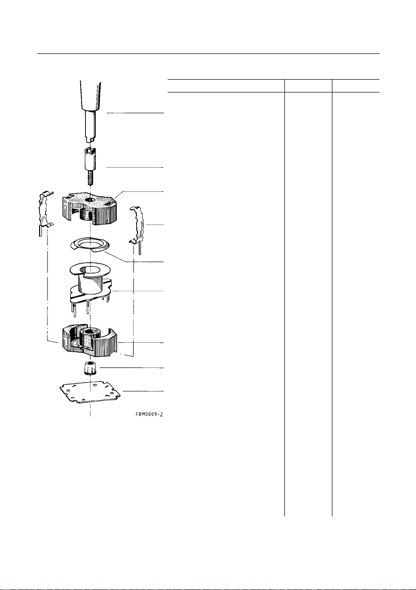
Core and Accessories
Individual parts Part no. Page
Adjusting screwdriver
(for assembly only)
Matching handle B63399 189
Adjusting screw B65539 189
Core B65803 185
Clamps B65806 188
Insulating washer 1 B65804 188
Coil former B65804 187
Core B65803 185
Threaded sleeve
(glued-in)
Insulating washer 2 B65804 188
B63399 189
Example of an assembly set
Also available: RM 4 low profile:
Core B65803-P 193
Coil former B65804 194
Clamp B65804 195
Insulating washer 1 + 2 B65804 195
SMD coil former B65804 196
184 Siemens Matsushita Components
Page 2
RM 4
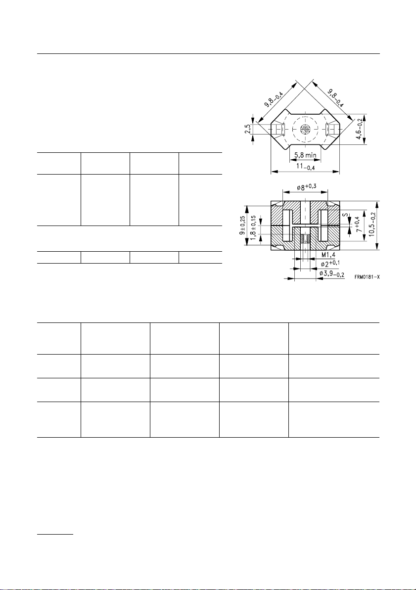
Core
● In accordance with IEC 60431
● Core without center hole
for transformer applications
● RM cores are supplied in sets
Magnetic characteristics (per set)
with
center hole
Σ
l/A
l
e
A
e
A
min
V
e
1,9
21
11
232
Approx. weight (per set)
m
1,45 1,65 g
Gapped
Material
A
value
L
nH
K1 16 ± 3 % 1,0 24,2 B65803-+16-A1
25 ± 3 % 0,40 37,8 B65803-+25-A1
M33 40 ± 3 % 0,36 60,4 B65803-+40-A33
63 ± 3 % 0,18 95 B65803-+63-A33
N48 63 ± 3 % 0,16 95 B65803-+63-A48
100 ± 3 % 0,10 151 B65803-+100-A48
160 ± 3 % 0,06 242 B65803-+160-A48
without
center hole
1,7
22
13
11,3
286
s
approx.
mm
mm
mm
mm
mm
mm
–1
2
2
3
µ
e
Ordering code
1)
-A with center hole
-N with threaded sleeve
B65803
1) Replace the + by the code letter “A” or “N” for the required version.
Siemens Matsushita Components 185
Page 3
RM 4
Core B65803
Ungapped
Material
A
value
L
µ
A
L1min
P
V
e
Ordering code
nH
nH
W/set
-J w/o center hole
N30 1900 + 30/– 20 % 2570 B65803-J-R30
T35 2800 + 40/– 30 % 3790 B65803-J-Y35
T38 3700 + 40/– 30 % 5000 B65803-J-Y38
N49 750 + 30/– 20 % 1010 450 0,04
B65803-J-R49
(50 mT, 500 kHz, 100 °C)
N87 1100 + 30/– 20 % 1480 650 0,20
B65803-J-R87
(200 mT, 100 kHz, 100 °C)
186 Siemens Matsushita Components
Page 4
RM 4
Accessories
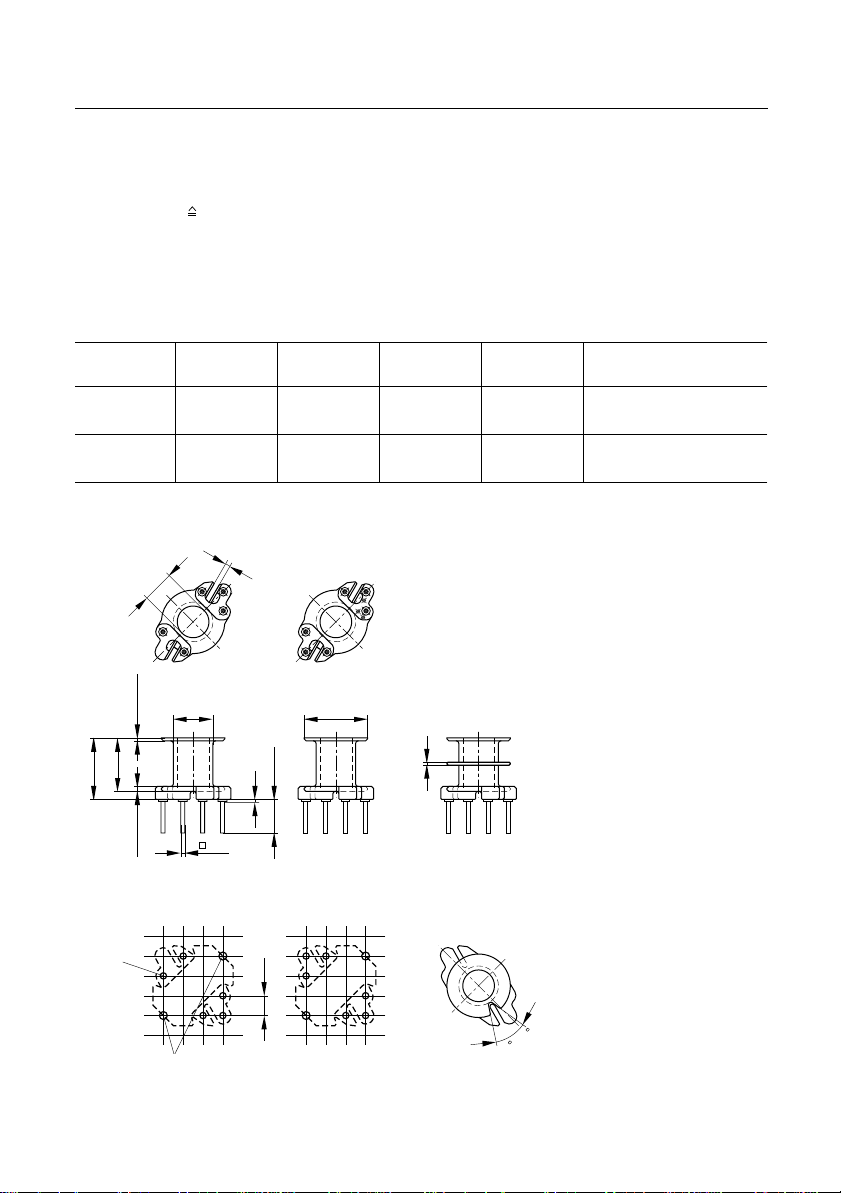
Coil former
Material: GFR thermosetting plastic (UL 94 V-0, insulation class to IEC 60085:
H max. operating temperature 180 °C), color code black
Solderability: to IEC 60068-2-20, test Ta, method 1 (aging 3): 235 °C, 2 s
Resistance to soldering heat: to IEC 60068-2-20, test Tb, method 1B: 350 °C, 3,5 s
Winding: see page 152
Squared pins
For matching clamp and insulating washers see page188
B65804
Sections
A
mm
N
2
l
N
mm
A
valueµΩPins Ordering code
R
1 8,7 20,1 80 5 B65804-N1005-D1
6 B65804-N1006-D1
2 8,1 20,1 85 5 B65804-N1005-D2
6 B65804-N1006-D2
5 pins 6 pins
0,6+0,1
6
4+0,15
5
3
ø4,9 0,1
0,42±0,050,65±0,05
0,17,65
_
_
6,85 0,1
0,45
Hole arrangement
Lochgrupppen
View in mounting direction
Ansicht in Montagerichtung
1
2
4,4±0,3
0,2
6
1
5
4
2
3
__
0,2ø7,9
0,4±0,05
ø1+0,1
2,54
_
10
Erdungspunkte ø1,3+0,1
Ground Ø 1,3+0,1
FRM0264-E
50
Siemens Matsushita Components 187
Page 5

RM 4
Accessories
B65804
B65806
Clamp
● With ground terminal, made of stainless spring steel (tinned), 0,335 mm thick
● Solderability to IEC 60068-2-20, test Ta, method 1 (aging 3): 235 °C, 2 s
● Also available as strip clamp on reels
Insulating washer 1 between core and coil former
● For tolerance compensation and for insulation
● Made of polycarbonate (UL 94 V-0, insulation class to IEC 60085: E 120 °C), 0,06 mm thick
Insulating washer 2 for double-clad PCBs
● Made ofpolycarbonate (UL 94 V-0, insulation class to IEC 60085: E 120 °C), 0,3 mm thick
Ordering code
Clamp (ordering code per piece, 2 are required) B65806-A2203
Insulating washer 1 (reel packing, PU = 1 reel) B65804-A5000
Insulating washer 2 (bulk) B65804-C2005
Clamp Insulating washer 1 Insulating washer 2
Clamping forces for RM 4
F
: Extension of clamp froma to
min
F
: Extension of clamp froma to
max
a
=
X
2
min
a
=
X
1
max
Clamp openinga (mm) 8,3 + 0,15
Core nose
Height of core pairX (mm)
Clamping forceF (N)
Z
(mm) 0,15
max
X
X
F
F
min
max
min
max
8,75
9,25
5
40
188 Siemens Matsushita Components
Page 6

RM 4
Accessories
Adjusting screw
● Tube core with thread and core brake made of GFR polyterephthalate
Plastic adjusting screwdriver (not shown)
Plastic handle for adjusting screwdriver (not shown)
Core RM 4 Adjusting screw Min.
Tube core
Material
K 1 16 1,81 × 2,0 Si 1 black 20 B65539-C1003-X101
M 33 40 1,81 × 2,0 Si 1 black 17 B65539-C1003-X101
N 48 63 1,81 × 2,0 Si 1 black 12 B65539-C1003-X101
Adjusting screwdriver B63399-B4
Handle B63399-B5
A
valuenH∅× lengthmmMaterial Color
L
25 1,81 × 2,0 K 1 yellow 21 B65539-C1003-X1
63 1,81 × 2,0 K 1 yellow 21 B65539-C1003-X1
100 1,81 × 2,0 K 1 yellow 17 B65539-C1003-X1
160 1,81 × 2,7 N 22 red 12 B65539-C1002-X22
code
adjusting
range
%
Ordering code
B65539
B63399
Adjusting screw
Siemens Matsushita Components 189
Page 7

RM 4
Inductance adjustment curves (nominal values)
Relative inductance change ∆
0 at least 1 turn engaged.
L/L
versus turnsNof adjusting screw.
Adjusting screw B65539-C1003-X101
Color code black
Adjusting screw B65539-C1002-X22
Color code red
Adjusting screw B65539-C1003-X1
Color code yellow
190 Siemens Matsushita Components
Page 8

B
B
RM 4
Q factor characteristics (typical values)
Material
K 1 25 nH 5,20
M 33 63 nH 770
A
L
valueLµH
183
Turns Wire; RF litz wire Sec-
14
2,65
1,27
10
7
100
52
54,5
29
45 × 0,04 CuLS
0,5 CuL
0,6 CuL
20 × 0,04 CuL
45 × 0,04 CuL
90 × 0,04 CuL
tions∅*mm
1
1
1
1
1
1
6,6
6,6
6,4
—
—
—
RF litz wire
Enamel copper
wire
K 1
A
= 25 nH
L
Flux density
in the core
< 0,5 mT
M 33
A
= 63 nH
L
Flux density
in the core
< 1 mT
Siemens Matsushita Components 191
Page 9

B
RM 4
Q factor characteristics (typical values)
Flux density in the core < 1 mT
Mate-
rial
A
N 48 —
1,00
3,24
9,60
3,25
= 100 nH
L
L
(mH) for Turns Wire; RF litz wire Sec-
A
= 160 nH
L
0,43
1,60
5,18
15,40
5,35
RF litz wire
Enamel copper
wire
52
100
180
310
183
45 × 0,04 CuLS
20 × 0,04 CuLS
0,18 CuL
0,14 CuL
10 × 0,05 CuL
tions
1
1
1
1
1
N 48
A
= 100 nH
L
N 48
A
= 160 nH
RF litz wire
Enamel coppe
wire
L
192 Siemens Matsushita Components
Page 10

RM 4 »Low Profile«
Core
● For compact transformers with high inductance
● Without center hole
● RM cores are supplied in sets
Magnetic characteristics (per set)
A
–1
2
2
3
value
L
µ
A
e
L1min
Σ
l/A
= 1,2 mm
l
= 17,3 mm
e
A
= 14,5 mm
e
A
= 11,3 mm
min
V
= 251 mm
e
Approx. weight 1,2 g/set
Ungapped
Material
B65803-P
P
V
Ordering code
nH
nH
W/set
T38 5000 + 40/– 30 % 4770 B65803-P-Y38
N49 860 + 30/– 20 % 820 630 0,03
B65803-P-R49
(50 mT, 500 kHz, 100 °C)
N87 1300 + 30/– 20 % 1234 950 0,09
B65803-P-R87
(200 mT, 160 kHz, 100 °C)
Siemens Matsushita Components 193
Page 11

RM 4 »Low Profile«
Accessories B65804
Coil former
Material: GFR thermosetting plastic (UL 94 V-0, insulation class to IEC 60085:
H max. operating temperature 180 °C), color code blue
Solderability: to IEC 60068-2-20, test Ta, method 1 (aging 3): 235 °C, 2 s
Resistance to soldering heat: to IEC 60068-2-20, test Tb, method 1B: 350 °C, 3,5 s
Winding: see page 160 (as SMD coil former)
Pins squared in the start-of-winding area
For matching clamp and insualting washers see page195
Sections
A
mm
N
2
l
N
mm
A
valueµΩPins Ordering code
R
1 4,7 20,1 147 6 B65804-R1006-D1
0,6+0,1
6
4+0,15
5
4
0,14,23
_
ø4,9 0,1
0,45±0,05
_
4,98 0,1
0,65±0,05
ø1+0,1
1
2
3
_
0,2ø7,9
_
ø0,52 max.
4,4±0,3
0,45 max.
2,54
_
Ground Ø 1,3+0,1
Erdungspunkte ø1,3+0,1
FRM0265-M
50
10
Hole arrangement
View in mounting direction
194 Siemens Matsushita Components
Page 12

RM 4 »Low Profile«
Accessories
Clamp
● With and without ground terminal, made of stainless spring steel, 0,3 mm thick, clamp with
ground terminal tinned
● Solderability to IEC 60068-2-20, test Ta, method 1 (aging 3): 235 °C, 2 s
● Clamping force 40 N per pair of clamps (typical value)
● Also available as strip clamp on reels on request
Insulating washer 1 between core and coil former
● For tolerance compensation and for insulation
● Made of polycarbonate (UL 94 V-0, insulation class to IEC 60085: E 120 °C), 0,06 mm thick
Insulating washer 2 for double-clad PCBs
● Made of polycarbonate (UL 94 V-0, insulation class to IEC 60085: E 120 °C), 0,3 mm thick
Ordering code
Clamp with ground terminal (ordering code per piece, 2 are required) B65804-P2203
Clamp without ground terminal (ordering code per piece, 2 are required) B65804-P2204
Insulating washer 1 (reel packing, PU = 1 reel) B65804-A5000
Insulating washer 2 (bulk) B65804-C2005
Clamp with ground terminal Clamp without ground terminal
B65804
Insulating washer 1 Insulating washer 2
Siemens Matsushita Components 195
Page 13

RM 4 »Low Profile«
Accessories B65804
SMD coil former with J terminals
Material: GFR liquid crystal polymer (UL 94 V-0, insulation class to IEC 60085:
F max. operating temperature 155 °C), color code black
Solderability: to IEC 60068-2-20, test Ta, method 1 (aging 3): 235 °C, 2 s
Resistance to soldering heat: to IEC 60068-2-20, test Tb, method 1B: 350 °C, 3,5 s
permissible soldering temperaturefor wire-wrapconnection on coil former: 400 °C,1s
Winding: see page 160
Clamp
● Without ground terminal, made of stainless spring steel, 0,3 mm thick
● Also available as strip clamp (each carton containing 2 reels), also on a reel on request
Sections
A
mm
N
2
l
N
mm
A
valueµΩTermi-
R
nals
1)
Ordering code
1 5,0 20,1 138 10 B65804-B6010-T1
2 4,4 20,1 157 10 B65804-B6010-T2
Clamp (ordering code per piece, 2 are required) B65804-P2204
Coil former Clamp
1 section 2 sections
Recommended
PCB layout
1) 6 and 8 terminals on request
196 Siemens Matsushita Components
 Loading...