

Page 1
AXIOM Iconos R200 with
fixed table height
Operator Manual
AXIOM Iconos R200 with
fixed table height
Operator Manual
ückenschild für Ordner A4 (50 mm Rückenbreite); Zuschneiden auf 205 mm x 50 mm
AXIOM Iconos R200 with
fixed table height
Operator Manual
AXIOM Iconos R200 with
fixed table height
Operator Manual
ückenschild für Ordner A4 (30 mm Rückenbreite); Zuschneiden auf 205 mm x 23 mm
XD3-340.620.13.01.02 AXD3-340.620.13.01.02 AXD3-340.620.13.01.02 AXD3-340.620.13.01.02
rucknummer zum Aufkleben
Page 2

Page 3
Safety
1
AXIOM
System Overview
System Operation
Examination
Generator
Digital Image Processing
Interventional Application
2
3
4
5
6
7
Operating Manual
AXIOM Iconos R200
with fixed table height
© Siemens AG 2002
All rights reserved
Stands/Tube Supports
Bucky Wall Unit
System Configuration/Options
Accessories
Exposure Table
8
9
10
11
12
13
Order No.: AXD3-340.620.13.01.02
Printed in the Federal Republic of Germany
AG 12.2007
Siemens AG Siemens AG, Medical Solutions AX
Wittelsbacherplatz 2 Siemensstrasse 1
DE-80333 Muenchen D-91301 Forchheim
Germany Germany
Contact Information:
Phone: +49 9191 18-0
Addendum/Current Information
Technical Description
14
15
Page 4
Important information from the
manufacturer
This product is provided with a CE marking in accordance with the
regulations stated in Appendix II of the Directive 93/42/EEC of June
14th, 1993 concerning medical devices.
In accordance with Appendix IX of the Directive 93/42/EEC, this
device is assigned to class II b.
The CE marking applies only to medical devices which have been
put on the market according to the above-mentioned EC Directive.
Unauthorized changes to this product invalidate this declaration.
Please observe the Safety Operator Manual.
Important information is given there.
The original version of this manual was written in English.
Page 5

AXIOM Iconos R200
Overall Table of Contents
Lists
Operator Manual
Overall Table of Contents
Part: Lists
Chapter: Overall Table of Contents....................................................................................................... 1
Part: System Overview
Chapter: System Description.................................................................................................................. 5
Application ............................................................................................................................................ 5
Product description ............................................................................................................................... 5
System configuration ............................................................................................................................ 6
System overview .................................................................................................................................. 7
Unit overview ........................................................................................................................................ 8
Chapter: Protective Measures.............................................................................................................. 11
Emergency Procedures ....................................................................................................................... 11
Cleaning and disinfection .................................................................................................................... 11
Radiation protection zones .................................................................................................................. 12
Mechanical safety ............................................................................................................................... 15
Safety-relevant parts subject to wear ................................................................................................. 22
Maintenance intervals ......................................................................................................................... 22
CAREWATCH ...................................................................................................................................... 22
Chapter: Operating and Display Elements ........................................................................................ 25
System remote control console .......................................................................................................... 25
Generator on/off console .................................................................................................................... 32
Foot switch for fluoroscopy and radiography in the control room ...................................................... 33
Tableside control panel ....................................................................................................................... 33
LCD Monitor ....................................................................................................................................... 35
Primary collimator ............................................................................................................................... 36
Part: System Operation
Chapter: On-Off/Emergency Stop......................................................................................................... 5
Switching the system on ...................................................................................................................... 5
Switching the system off ...................................................................................................................... 6
Emergency SHUTDOWN button (installed on-site) .............................................................................. 6
Standby power supply .......................................................................................................................... 6
Red Emergency STOP button ............................................................................................................... 7
Patient rescue ....................................................................................................................................... 8
AXIOM Iconos R200 AXD3-340.620.13.01.02 1 / 4
Page 6

AXIOM Iconos R200
Overall Table of Contents
Chapter: Functional and Safety Check................................................................................................. 9
Daily tests ............................................................................................................................................. 9
Monthly tests ...................................................................................................................................... 10
Legally required tests .......................................................................................................................... 10
Chapter: System Settings...................................................................................................................... 11
General notes ...................................................................................................................................... 11
Moving the X-ray system longitudinally .............................................................................................. 14
Tabletop .............................................................................................................................................. 15
Tube assembly stand .......................................................................................................................... 17
Tabletop .............................................................................................................................................. 18
Compression device (optional) ............................................................................................................ 21
Tomographic equipment (optional) ..................................................................................................... 22
Manual tube assembly rotation ........................................................................................................... 24
Moving the grid into / out of the beam path ....................................................................................... 24
Setting the source-image distance ..................................................................................................... 25
Chapter: Setting the Image Geometry ............................................................................................... 27
Limiting the radiation field (collimation) .............................................................................................. 27
CAREPOSITION (optional) .................................................................................................................. 29
Additional Cu filter ............................................................................................................................... 30
Image reversal .................................................................................................................................... 30
Switching over the image intensifier format ....................................................................................... 31
Part: Examination
Chapter: Transferring and Positioning the Patient ............................................................................ 5
General information .............................................................................................................................. 5
Positioning the patient .......................................................................................................................... 5
Chapter: Fluoroscopy ................................................................................................................................7
Fluoroscopy operating modes .............................................................................................................. 7
Selecting the fluoroscopy operating mode ........................................................................................... 7
Changing the selection of the fluoroscopy operating mode ................................................................. 7
Releasing fluoroscopy ........................................................................................................................... 9
Fluoroscopic data .................................................................................................................................. 9
Automatic fluoroscopic control ........................................................................................................... 10
Fluoroscopy time limit ......................................................................................................................... 11
Fluoroscopy warning signal ................................................................................................................. 11
Automatic format collimation in fluoroscopy ...................................................................................... 11
Fluoroscopy programs ........................................................................................................................ 11
Dose reduction .................................................................................................................................... 12
Chapter: Cassette Exposures in the Spotfilm Device (optional) ................................................. 13
Automatic format collimation in radiography ...................................................................................... 13
Cassette program ............................................................................................................................... 14
Loading / unloading the spotfilm device ............................................................................................. 16
2 / 4 AXD3-340.620.13.01.02 Operator Manual
Page 7

AXIOM Iconos R200
Overall Table of Contents
Exposure measurement for cassette exposures ................................................................................ 17
Releasing the exposure ...................................................................................................................... 19
Organ programs .................................................................................................................................. 19
Single exposures / serialography ........................................................................................................ 19
Bucky mode ........................................................................................................................................ 20
Spotfilming without tomography ........................................................................................................ 20
Tomography (optional) ........................................................................................................................ 21
Chapter: Digital Radiography................................................................................................................. 23
Automatic format collimation in digital radio-graphy ...........................................................................23
Exposure measurement in digital radiography ....................................................................................23
Spotfilming without tomography ........................................................................................................ 25
Tomography (optional) ........................................................................................................................ 27
Periscanning ........................................................................................................................................ 30
Peristepping (optional) ........................................................................................................................ 34
DR-Scanning (optional) ........................................................................................................................ 40
Chapter: Free Cassette Exposure ....................................................................................................... 49
Collimation on exposure ..................................................................................................................... 49
Selecting the exposure technique ...................................................................................................... 49
Releasing an exposure ........................................................................................................................ 50
Chapter: Cassette exposures with wall stand ................................................................................. 51
Collimation during exposure ............................................................................................................... 51
Selecting the exposure technique ...................................................................................................... 51
Releasing the exposure ...................................................................................................................... 52
Part: POLYDOROS SX 65/80
Chapter: Integrated Control Console .................................................................................................... 3
Application ............................................................................................................................................ 3
Configuration ......................................................................................................................................... 3
Overview of the controls and displays .................................................................................................. 4
Explanation of displays and controls ..................................................................................................... 9
Messages ........................................................................................................................................... 10
Tube load computer ............................................................................................................................ 10
Functional and safety checks .............................................................................................................. 12
Fluoroscopy ........................................................................................................................................ 13
Exposure ............................................................................................................................................. 15
Organ programs .................................................................................................................................. 32
Part: Accessories
Chapter: Preliminary Remarks ................................................................................................................ 3
Proper use of the product ..................................................................................................................... 3
Safety .................................................................................................................................................... 3
AXIOM Iconos R200 AXD3-340.620.13.01.02 3 / 4
Page 8

AXIOM Iconos R200
Overall Table of Contents
Orientation ............................................................................................................................................ 3
Use of several accessory components ................................................................................................. 4
Chapter: Standard Accessories.............................................................................................................. 5
Grip protection strip .............................................................................................................................. 5
Handgrip strip ....................................................................................................................................... 6
Handgrip ............................................................................................................................................... 8
Shoulder supports ................................................................................................................................. 9
Footboard ............................................................................................................................................ 10
Chapter: Optional Accessories............................................................................................................. 13
Head support ...................................................................................................................................... 13
Knee crutches ..................................................................................................................................... 15
Compression belt ................................................................................................................................ 17
Footboard Extension ........................................................................................................................... 21
Foot restraint ...................................................................................................................................... 23
Cup holder .......................................................................................................................................... 26
IV holder .............................................................................................................................................. 27
Lateral cassette holder ........................................................................................................................ 29
Foot switch assemblies for fluoroscopy and radiography ................................................................... 33
Armrest ............................................................................................................................................... 35
Lateral radiation shield ........................................................................................................................ 36
Holder for BABIX cradles .................................................................................................................... 38
BABIX cradles ..................................................................................................................................... 40
BABIX hanger ...................................................................................................................................... 42
Holder for pediatric cradle, manual ..................................................................................................... 43
Patient positioning mattress ............................................................................................................... 43
Compression cones ............................................................................................................................ 44
Radiation protection for tableside examinations ................................................................................. 47
Radiation protection for the upper body ............................................................................................. 49
Compensating filters ........................................................................................................................... 51
Holding device for eight filters ............................................................................................................ 53
Three-field templates .......................................................................................................................... 54
Part: Technical Description
Chapter: Identifying Labels...................................................................................................................... 3
Position of the labels ............................................................................................................................. 3
Chapter: Technical Data............................................................................................................................ 5
System .................................................................................................................................................. 5
Unit ....................................................................................................................................................... 6
Components ......................................................................................................................................... 8
X-ray generator .................................................................................................................................... 11
4 / 4 AXD3-340.620.13.01.02 Operator Manual
Page 9

System Overview
Table of Contents
Operator Manual
System Overview
Chapter: System Description
Application .......................................................................................................................... 5
Product description ............................................................................................................5
System configuration .......................................................................................................... 6
Standard version .................................................................................................... 6
Options ......................................................................................................................... 6
System overview ................................................................................................................7
Unit overview ..................................................................................................................... 8
Chapter: Protective Measures
Emergency Procedures .................................................................................................... 11
Cleaning and disinfection .................................................................................................. 11
Radiation protection zones ............................................................................................... 12
Position and size of the main operating area ....................................................................... 12
Stray radiation in the main operating area according to DIN EN 60601-1-3 ................................. 14
Mechanical safety ............................................................................................................. 15
Danger zones with unit in horizontal position ...................................................................... 15
Danger zones with unit in vertical position .......................................................................... 16
Warning signs .............................................................................................................. 16
Grip locations ............................................................................................................... 17
Danger zones ............................................................................................................... 17
Patient positioning ......................................................................................................... 18
Patient positioning with unit in vertical position ................................................................... 19
Remote compression (optional) ........................................................................................ 19
Safety devices .............................................................................................................. 19
Possible collisions of the system with a ceiling-mounted support ............................................ 20
Measures for avoiding equipment damage ......................................................................... 20
Measures for avoiding unwanted radiation ......................................................................... 21
AXIOM Iconos R200 AXD3-340.620.13.01.02 1 / 44
Page 10

System Overview
Table of Contents
Safety-relevant parts subject to wear ............................................................................... 22
Maintenance intervals ...................................................................................................... 22
CAREWATCH ................................................................................................................... 22
Display data ................................................................................................................. 22
Resetting the area dose product ...................................................................................... 23
Chapter: Operating and Display Elements
System remote control console ....................................................................................... 25
Displays general ........................................................................................................... 25
Indicators in the display .................................................................................................. 25
System settings ............................................................................................................ 26
Image intensifier formats ................................................................................................ 27
Automatic fluoroscopy control ......................................................................................... 28
Image reversal .............................................................................................................. 28
Additional filter ............................................................................................................. 28
Collimator settings ........................................................................................................ 28
Semitransparent filters ................................................................................................... 29
Radiation release .......................................................................................................... 29
Stop button ................................................................................................................. 29
General operating elements ............................................................................................ 29
Preselection functions .................................................................................................... 30
Operating modes .......................................................................................................... 30
Segmentation program ................................................................................................... 31
Generator on/off console .................................................................................................. 32
Foot switch for fluoroscopy and radiography in the control room .................................... 33
Tableside control panel ..................................................................................................... 33
Displays ...................................................................................................................... 33
System settings ............................................................................................................ 34
Image intensifier formats ................................................................................................ 35
Collimator settings ........................................................................................................ 35
LCD Monitor ..................................................................................................................... 35
Primary collimator .............................................................................................................36
Control elements and displays at the front ......................................................................... 36
Control elements at the underside .................................................................................... 38
Prefilter selection .......................................................................................................... 40
Motorized prefilter selection ................................................................................... 40
Manual prefilter selection ....................................................................................... 40
2 / 44 AXD3-340.620.13.01.02 Operator Manual
Page 11

System Overview
Table of Contents
Changing the bulb of the laser light localizer ....................................................................... 41
Testing the fit of the new bulb ................................................................................ 43
Accessories and auxiliary devices ..................................................................................... 43
AXIOM Iconos R200 AXD3-340.620.13.01.02 3 / 44
Page 12

System Overview
Table of Contents
4 / 44 AXD3-340.620.13.01.02 Operator Manual
Page 13

System Overview
System Description
Application
The ICONOS R200 is an X-ray system for universal use and is suitable both as
intensively used universal workstation and as a highly loaded special workstation.
You can perform examinations with the following techniques:
❏ Fluoroscopy through image intensifier and television system
❏ Cassette exposures with spotfilm device (optional)
– Spotfilms
– Bucky exposures
– Tomography (optional)
❏ Digital radiography DR
– Spotfilms
– Tomography (optional)
– Periscanning
– Peristepping (optional)
– DR scanning (optional)
– Digital subtraction angiography (optional)
❏ Tabletop cassette exposures
❏ Bed-side exposures
❏ Exposures onto the wall stand (optional)
Product description
ICONOS R200 universal X-ray diagnostic unit with swivelling overtable X-ray tube
assembly, oblique projection and tomography in all table positions and gently
starting and braking system movements.
Two-stage setting of the source-image distance.
Table tilt + 90° to - 17° with soft start and braking.
Motor-driven longitudinally and transversely moving tabletop.
Fully automatic spotfilm device with extensive subdivision program and 33 cm or
40 cm image intensifier or I.I. image receptor with 40 cm image intensifier, each
with a large axial travel range.
Fluoroscopy and imaging system with ergonomic remote control.
Integrated system movement control on the spotfilm device.
AXIOM Iconos R200 AXD3-340.620.13.01.02 5 / 44
Page 14

System Overview
System Description
System configuration
The label with MODEL NO.: 59 02 767 bears the CE 0123 marking for the entire
ICONOS R200 system and is attached to the back of the table frame.
Standard version
❏ ICONOS R200 system
❏ Cassette spotfilm device with image intensifier with SIRECON 33 cm or 40
cm image intensifier or I.I. image receptor with SIRECON 40 cm image intensifier
❏ VIDEOMED DH TV system (with DSA) or DHC (without DSA)
❏ OPTITOP X-ray tube assembly
❏ POLYDOROS SX X-ray generator
❏ Primary collimator
❏ Monitor trolley or ceiling suspension system
❏ 44 cm or 54 cm monitor(s)
❏ FLUOROSPOT Compact with DICOM Send and Storage Commitment
❏ Footswitch for fluoroscopy and radiography
Options
❏ DICOM functions:
–Get Worklist and MPPS
– Query/Retrieve
–Print
❏ Reference image monitor(s)
❏ VERTIX PRO/TOP Bucky wall unit
❏ 2nd X-ray tube assembly on the 3D-TOP ceiling-mounted support
❏ PACS/SIENET connection
❏ High-pressure contrast medium injector
❏ Measuring device for area dose product
❏ Mobile tableside console
6 / 44 AXD3-340.620.13.01.02 Operator Manual
Page 15
(2)
System Overview
System Description
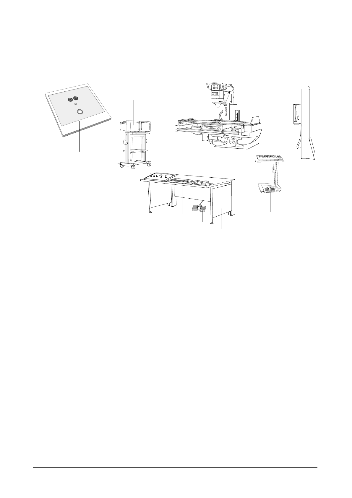
System overview
(1)
(3)
AXIOM
(4)
(5)
(6)
(7)
(8)
(9)
(1) ICONOS R200 examination unit
(2) Generator ON/OFF console
(3) Monitor trolley (optional)
(4) System remote control console
(5) FLUOROSPOT Compact keyboard
(6) Foot switch for fluoroscopy and radiography
(7) Desk (optional) for operating consoles
(8) Tableside control console with foot switch for fluoroscopy and radiography
(optional)
(9) Bucky wall unit (optional)
AXIOM Iconos R200 AXD3-340.620.13.01.02 7 / 44
Page 16
System Overview
System Description
(9)
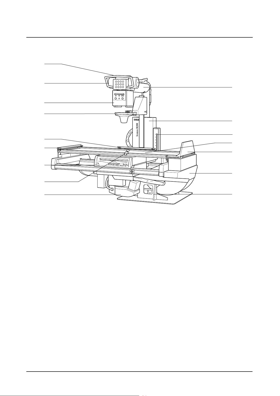
Unit overview
(8)
(7)
(6)
(5)
(4)
(3)
(2)
(1)
(10)
(11)
AXIOM
(12)
(13)
(14)
(15)
(16)
(1) Image intensifier TV system with safety shut-off device
(2) Handgrip (at the front), adjustable
(3) Cassette spotfilm device or I.I. receptor unit with tableside control panel and
removable scattered radiation grid
(4) Grip protection strip (head end), detachable
(5) Handgrip strip (located on back), adjustable, secure in all patient positions
(6) Compression device (optional)
for inserting a compression cone, continuously adjustable compression force
(7) Collimator with automatic format collimation and numerical format indication,
with integrated motor-driven additional Cu filters, motor-driven adjustable
semi-transparent filters (optional)
(8) X-ray tube assembly
air-cooled, partly enclosed, can be swivelled
(9) Handle for swivelling the tube assembly
(10) Tube assembly stand on the longitudinal carriage
coupled with the spotfilm device by centering rod, axially swivelling, telescopic (SID 115cm and 150cm)
(11) Longitudinal carriage with attached tube assembly stand
motorized longitudinal travel, precisely controllable speed
8 / 44 AXD3-340.620.13.01.02 Operator Manual
Page 17

System Overview
System Description
(12) Tomographic height display (option) with laser line light localizer
(13) Tabletop with flat accessory rails
motor-driven longitudinal and transverse travel
(14) Footboard
adjustable for use as seat,
with attachment points for foot restraints,
can be changed over from foot end to head end.
(15) Table frame
motor-driven adjustable in height, can be tilted + 90°/-17°
(16) Unit base with tilting drive on installation plate
AXIOM Iconos R200 AXD3-340.620.13.01.02 9 / 44
Page 18

System Overview
System Description
10 / 44 AXD3-340.620.13.01.02 Operator Manual
Page 19

System Overview
Protective Measures
Emergency Procedures
Warning
Due to the complexity of the system, the loss of X-ray imaging or other system
functions during an examination or procedure can not be completely excluded.
Risk of failure during interventions
◆ Consider therefore the need to establish emergency procedures in such cases.
Cleaning and disinfection
Caution
Use of harsh cleaning agents, liquids or sprays.
Risk of electrical hazard or damage to the system
◆ Use only substances for cleaning and disinfection, which are recommended.
◆ Do not let cleaning liquids seep into the openings of the system
(e.g. air openings, gaps between covers).
◆ Observe the following cleaning and disinfection instructions.
AXIOM Iconos R200 AXD3-340.620.13.01.02 11 / 44
Page 20
System Overview
Protective Measures
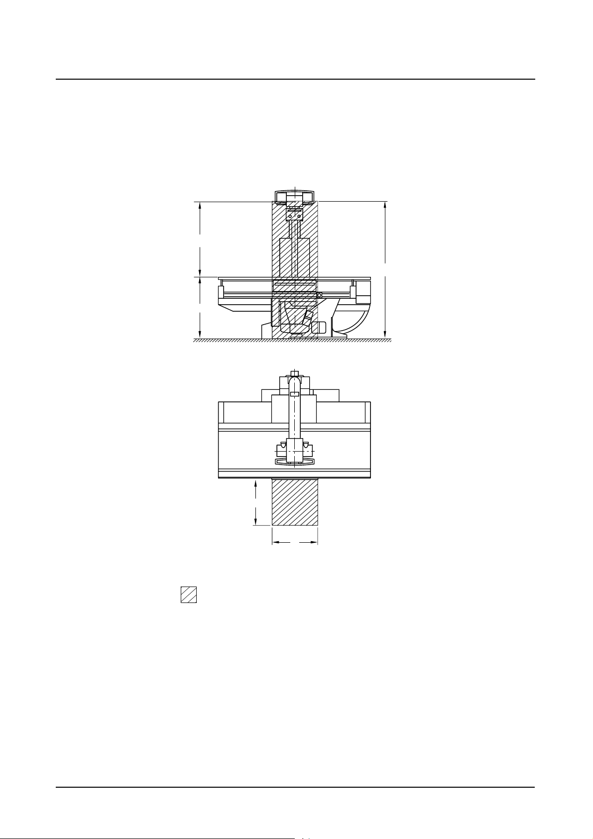
Radiation protection zones
Position and size of the main operating area
Horizontal patient table:
x
107
200
90
60
Main operating area
Dimensions in cm
60
12 / 44 AXD3-340.620.13.01.02 Operator Manual
Page 21
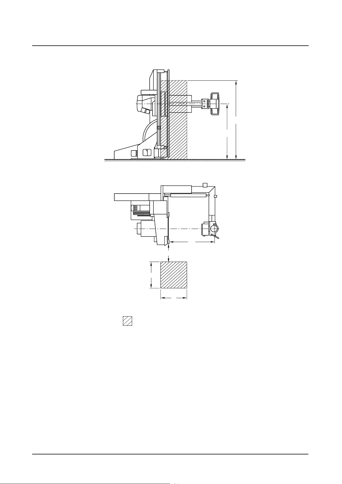
Vertical patient table:
System Overview
Protective Measures
x
200
140
40
60
60
Main operating area
Dimensions in cm
x
107
AXIOM Iconos R200 AXD3-340.620.13.01.02 13 / 44
Page 22
System Overview
Protective Measures
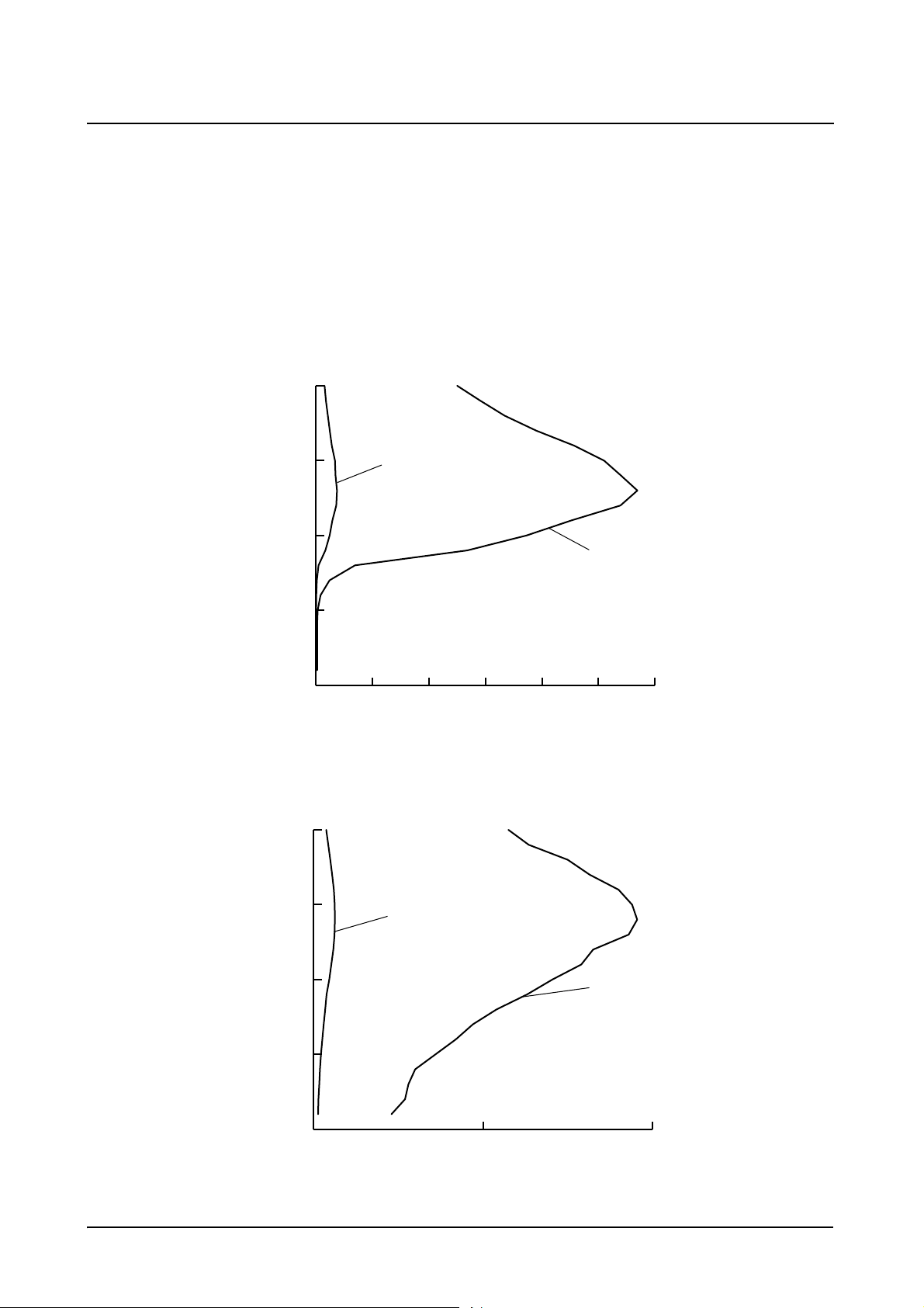
Patient table horizontal
Stray radiation in the main operating area according to DIN EN 60601-1-3
Tolerance of the air kerma measurements ± 5%
Characteristic A and C: continuous fluoroscopy 63kV, 0.8mA (antiisowatt)
Characteristic B and D: continuous fluoroscopy 110kV, 3mA
Height above floor
cm
200
Patient table vertical
150
100
50
0
0123456
Height above floor
cm
200
150
A
B
C
Air kerma
mGy/h
100
50
0
012
14 / 44 AXD3-340.620.13.01.02 Operator Manual
D
Air kerma
mGy/h
Page 23
System Overview
Protective Measures
Mechanical safety
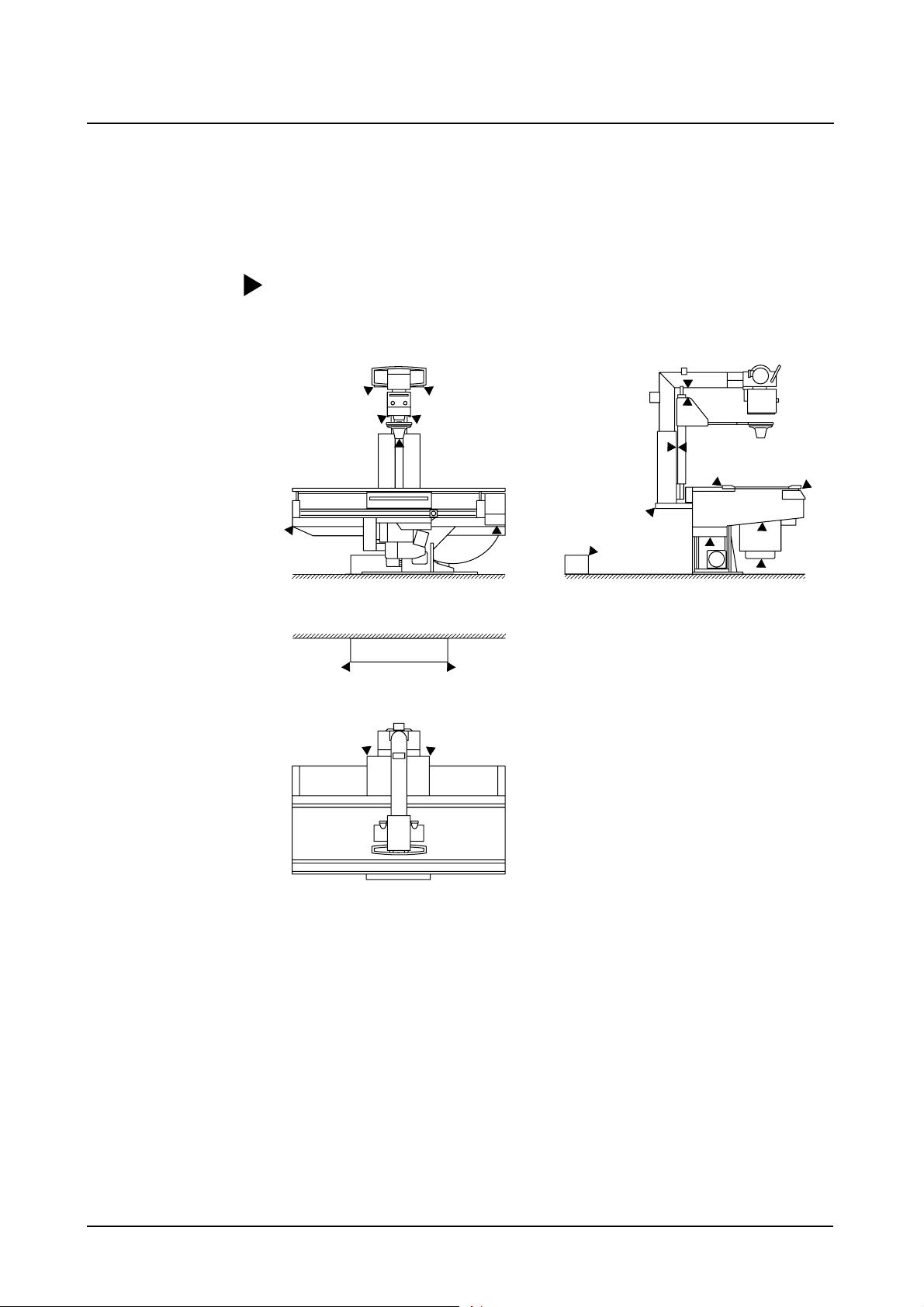
Danger zones with unit in horizontal position
The places marked in the illustrations show possible danger zones at which the
patient or operator can be injured.
AXIOM Iconos R200 AXD3-340.620.13.01.02 15 / 44
Page 24
System Overview
Protective Measures
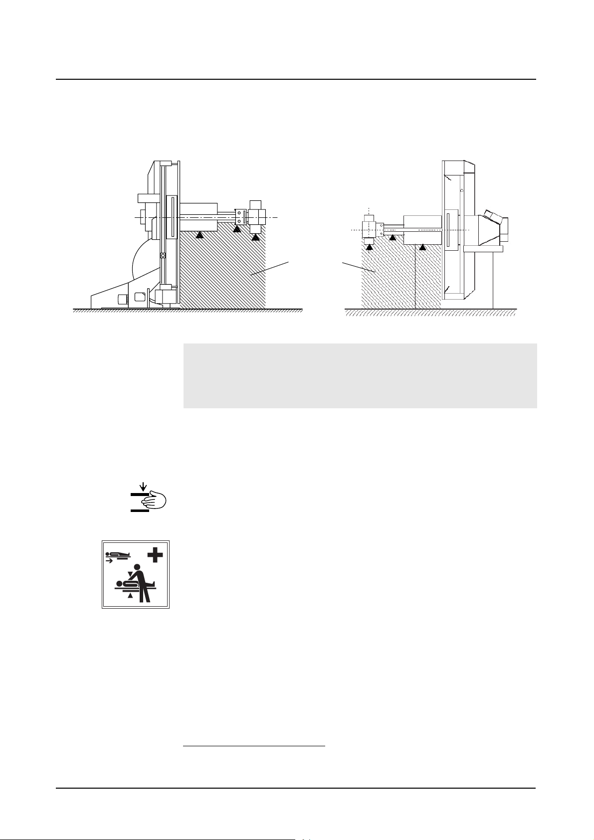
Danger zones with unit in vertical position
The places marked in the illustration indicate possible danger points where the
patient or operating personnel can be injured.
x
Danger zone
If the patient is located in the danger zone, it must always be ensured that the
operating personnel are in the room and within reach of an emergency stop.
If the operating personnel leaves the room and/or moves out of reach of an
emergency stop, then the patient has to be moved out of the danger zone.
1
Warning signs
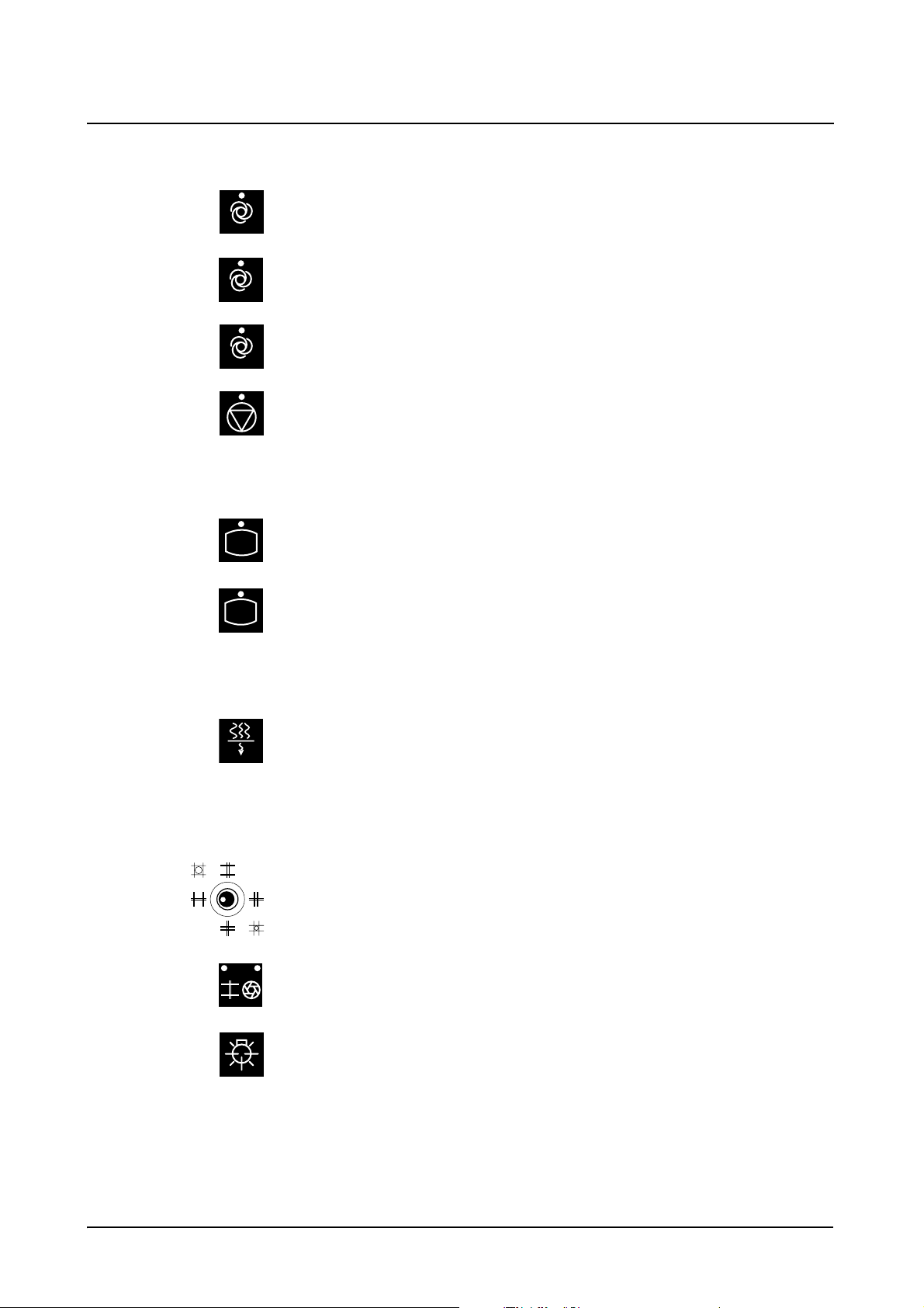
Special danger zones are marked on the unit with a warning sign.
This warning sign is a reference to a possible risk of injury by crushing for the patient and/or examiner.
This warning sign shows the position of the patient table in cardiopulmonary reanimation (CPR) with pressure compression up to 500N (50kg).
1
Between -90° and +90°, depending on the system version
16 / 44 AXD3-340.620.13.01.02 Operator Manual
Page 25
System Overview
Protective Measures
Grip locations
Warning
When handling the system correctly as well as when positioning the patient,
operators and patients should use only the grip locations
provided for this purpose.
The following grip locations are provided:
❏ 1 handgrip (front)
❏ Grip protection strip (head end)
❏ Handgrip strip (back)
◆ Ensure that the handgrip strip, the grip protection strip and the handgrip are
always attached.
If these grip locations cannot be used:
◆ Pay special attention to the stated possibilities of crushing between moving
parts and their guide openings.
◆ Ensure during the examination that the patient under no circumstances holds
on to the edges of the patient table.
Not intended as gripping point:
The handle for turning the tube assembly must not be used as grip location or
hold for the patient.
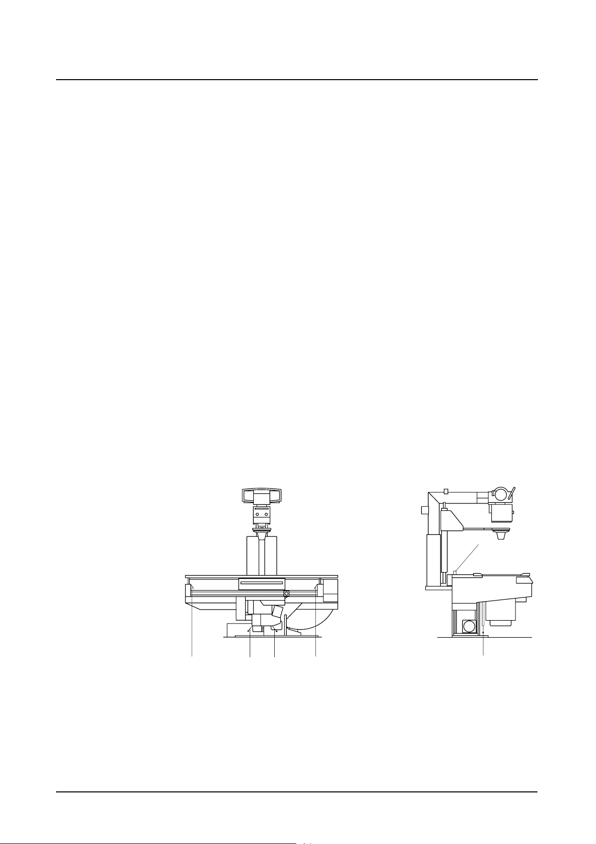
Danger zones
The dotted areas mark the danger zone, where no objects must be located during
tilting.
Danger zone
Movement range of the positioning table
◆ Prior to activating any movements of the unit, especially tilting of the unit,
make sure that there are no objects such as stairs, steps, stands, waste containers, instrument tables, beds, gurneys, monitor support systems, operating consoles or the like in its movement range.
AXIOM Iconos R200 AXD3-340.620.13.01.02 17 / 44
Page 26

System Overview
Protective Measures
These objects are not detected by the collision monitoring of the unit. Avoiding
collisions of the unit with these objects is subject to the operator’s duty to take
care.
If a collision of the unit with a rigid obstacle (e.g. step) has occurred,
◆ press one of the red emergency stop buttons,
◆ rescue the patient,
Warning
Under no circumstances must the unit be tilted down further or tilted up, since
externally invisible, but safety-relevant damage to the tilting drive may occur.
Severe consequential damage including personal damage cannot be excluded
in this case.
◆ immediately notify the SIEMENS Uptime Service.
❏ Avoid standing or sitting immediately adjacent to the system and especially
do not sit next to the system with your legs or knees under the cross-beam at
the head or foot end of the table.
❏ Take care that during system movements no one is in the area between the
unit base and table.
❏ Take care that with the footboard attached there is a risk of collision with the
extended cone (optional) when the tabletop and / or the longitudinal carriage
are moving.
❏ Do not grasp in the loading shaft of the spotfilm device because of the risk of
crushing.
Patient positioning
❏ All safety-related equipment must be installed and operable. In particular the
handgrip strips (head end and lateral), handgrip, footboard, foot restraints,
compression belt and shoulder supports.
❏ The patient’s hands, arms, legs, head and hair must not extend unsecured be-
yond the edge of the tabletop.
❏ Observe the patient while moving the tabletop and in system movements and
take care that any catheter is correctly located.
❏ In examinations with the table tilted up vertically, the footboard serves as an
adjustable step or seat.
– Ensure that the footboard is locked together with the tabletop on both
sides.
– Check the firm location of the footboard.
18 / 44 AXD3-340.620.13.01.02 Operator Manual
Page 27
System Overview
Protective Measures
Patient positioning with unit in vertical position
During examinations with the unit in the upright position there is a risk of crush
injuries to the patient if the X-ray system (stand with tube unit/receptor unit with
image intensifier) is moved in the longitudinal direction.
◆ Position the X-ray system approximately in the acquisition position.
◆ Move the patient into the acquisition position.
◆ Set the X-ray system to object height. Always watch the patient when initiat-
ing this movement.
Remote compression (optional)
❏ The motor-driven compression device requires special care on the part of the
examiner for the applied compression forces, especially in the case of frail
(e.g. infants), sick and elderly patients.
❏ Observe especially that both an increased risk of crushing for the patient with
consequential injury and considerable mechanical shearing forces with risk of
damage can occur between the compression cone and attached accessories,
e.g. shoulder supports, lateral support (optional) or motor-driven infant cradle
holder (optional) by collision during the motor-driven tabletop movement.
❏ When moving the compression carriage into the lowest position, the carriage
may collide with the patient’s hand on the grip protection strip.
– Use extreme caution when actuating the cone movement.
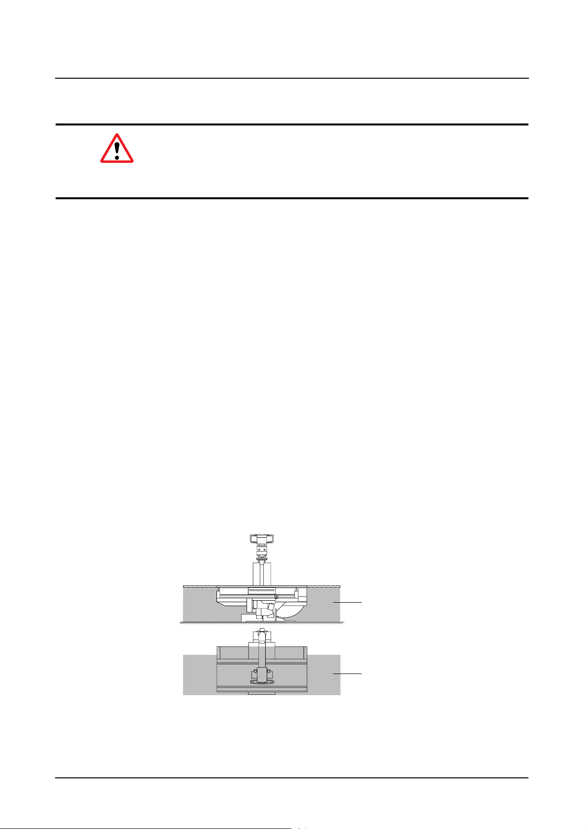
Safety devices
(1)
(3) (3)(2)
(1) Switch rail between tabletop and stand
(2) (3)
(2) Switch rails in each case at the end of the travel of the spotfilm unit
(3) Safety switching sensors on the image intensifier TV device (2 sensors))
AXIOM Iconos R200 AXD3-340.620.13.01.02 19 / 44
Page 28

System Overview
Protective Measures
On activation of one of the safety devices (shutdown devices) all system movements stop and are blocked.
This means that one cannot move out from the blockage oneself.
If it is not possible to remove the obstruction causing the problem, call in the Siemens Uptime Services.
Movements are possible again only after one of the safety devices has be deactivated.
Possible collisions of the system with a ceiling-mounted support
❏ System movements are possible only if the ceiling-mounted support is in its
park position or if the bypass switch is activated if necessary.
❏ Prior to actuating system movements with the bypass switch activated, verify
that no collision can take place with the ceiling-mounted support, the X-ray
tube assembly or the collimator. (No collision monitoring.)
1
Warning
If system movements are possible even though the ceiling-mounted support is
not in the park position and the bypass switch is not activated,
immediately press the emergency shutdown button and notify the
SIEMENS Uptime Service.
Measures for avoiding equipment damage
◆ Before activating system movements, especially tilting the table, make sure
that the movement range is free of obstructions.
◆ Move especially monitor support systems, operating consoles, gurneys, beds
and instrument tables out from the tilting range of the table and remove
chairs, steps, stands, waste containers and similar objects from the movement area. (No collision monitoring.)
◆ Do not place any objects or consumable material on the cover of the table support, on the spotfilm device and on the longitudinal guides of the stand carriage.
– Considerable forces which can damage these objects in the area of move-
ment of the systems arise during movements of the spotfilm device or of
the tabletop.
◆ Do not place any loose objects anywhere on the table.
– These objects could fall down when the table is tilted, causing injury or
damage.
1
optional
20 / 44 AXD3-340.620.13.01.02 Operator Manual
Page 29

System Overview
Protective Measures
◆ Do not stand at any place on the spotfilm device or on the covers of the table
support outside the marked areas provided for this.
– The covers can be deformed.
Components located underneath them are damaged and thus lead to operating disturbances.
◆ Place no objects on the operating areas of the control consoles and the tableside control.
Caution
Unintentional activation of control elements for movements
Collision with patient, operator or equipment
◆ Do not load the remote console with any objects, accessories, folders or
documents.
To avoid unintentional activation of control elements for movements concerning
bed exposure, please adhere to the following workflow:
◆ Select aquisition mode Bed exposure at the generator control console.
◆ Tilt the system and move it to the correct SID.
◆ Rotate the tube assembly accordingly.
◆ Position the patient.
◆ Control patient and system.
◆ Don’t let patient stay in system area during absence of operator.
◆ In vertical table positions do not use the stand column, the tube assembly sup-
port arm, the tube assembly cover or the primary collimator as seat or support.
– This unallowed loading can lead to material breakage and damage to bear-
ings.
◆ Never put contrast medium cups or open containers with liquid or pasty contents on the unit, on the remote console or on the control cabinets.
– Contrast medium can spill, leak or overflow into system parts and lead to
operational disturbances of the unit or to misinterpretation of exposures.
◆ When storing contrast medium in the cup holder on the compression carriage,
use only cups with a maximum volume of 0.25 liter made of unbreakable materials, i.e. under no circumstances glass or porcelain.
– Remove contrast medium traces immediately!
Measures for avoiding unwanted radiation
◆ Before starting system movements make sure that the foot switch for fluoroscopy and radiography (optional) in the examination room is not in the travel
range of the image intensifier light distribution system.
AXIOM Iconos R200 AXD3-340.620.13.01.02 21 / 44
Page 30

System Overview
Protective Measures
Safety-relevant parts subject to wear
This system contains no safety-relevant parts subject to wear.
Maintenance intervals
Maintenance must be performed annually in order to ensure the safety and functioning ability of the system.
If you have not concluded a maintenance contract, please notify the Siemens Uptime Service on time.
CAREWATCH
Display data
At the start of fluoroscopy/acquisition the following system parameters are displayed in the lower right area of the live monitor:
1st line
– Display of the prefilter in fluoroscopy
2nd line
– Display of the prefilter in radiography
With the area dose product meter (optional)
3rd line
– Area dose product in cGycm²
4th line
During fluoroscopy
– Display of the patient entrance dose
In the radiation pauses
– the percentage of the patient entrance dose reached related to a config-
1
urable limit
– the accumulated patient entrance dose in mGy is displayed.
of 0.5 to 5 Gy or
1
2
in mGy/min
The measuring device must be calibrated at regular intervals. This is done within
the scope of a maintenance contract. If no maintenance contract have been concluded, the measuring device can be calibrated by the Siemens Uptime Service
of the manufacturer.
1
can be configured by the SIEMENS Uptime Service
2
standardized to 30 cm above the tabletop
22 / 44 AXD3-340.620.13.01.02 Operator Manual
Page 31

System Overview
Protective Measures
Resetting the area dose product
Once the examination is finished,
◆ actuate the reset button at the integrated generator control console
– The displays for the area dose product and the patient entrance dose are
reset to zero.
➩ Refer to the Operator Manual of Fluorospot Compact.
AXIOM Iconos R200 AXD3-340.620.13.01.02 23 / 44
Page 32

System Overview
Protective Measures
24 / 44 AXD3-340.620.13.01.02 Operator Manual
Page 33

System Overview
Operating and Display Elements
DR DR DR
1 2 3
1 2 3
System remote control console
DR
R
R
Displays general
Start
1,50
1,15
1
STOP
❏ "Radiation ON" indicator
– Symbol lights up orange
❏ “Generator is busy” indicator
– Symbol lights up orange
Indicators in the display
+15 ˚
-10˚
8
0.1mm
E471
Lo
❏ Oblique projection angle
❏ Table tilt angle
2
5/3
DR
mm521
s2.1˚04
gelgn-<
2
1
User interface is identical for the optional mobile tableside control console
2
depending on the operating mode
AXIOM Iconos R200 AXD3-340.620.13.01.02 25 / 44
Page 34

System Overview
DR
Operating and Display Elements
❏ Display of the set compression level, only in connection with the compression
❏ Additional Cu filter swivelled in
❏ Cassette exposures available in film segmentation
device (optional)
– only with cassette spotfilm device
DR
E474 ❏ Error message
< - Longleg ❏ Scanning technique (DR scanning) selected
30 cm * 24 cm ❏ Display of the cassette size
❏ Current position and maximum possible exposure positions in Peristepping
(optional)
❏ Fulcrum height (axial oblique projection = isocenter) or tomographic height
(optional)
❏ Selected tomographic program (angle, time)
or
System settings
❏ Compression device (optional)
– decompress
– compress
❏ without function
❏ Joystick for table tilt down/tilt up
❏ Oblique projection (cranio-caudal/caudo-cranial)
26 / 44 AXD3-340.620.13.01.02 Operator Manual
Page 35

System Overview
Startt
Operating and Display Elements
❏ Oblique projection +/- 0º (orthogonal projection)
❏ Joystick for
– X-ray system longitudinal movement
– Tabletop transverse movement
❏ Coordinate switch for moving tabletop longitudinally/transversely
❏ Fulcrum height for oblique projection (= isocenter)
❏ Tomographic height setting above tabletop (optional)
1,50
1,15
Star
❏ Move cassette into unloading position
– only with cassette spotfilm device
❏ Source-image distance with cassette spotfilm device (115 cm, 150 cm)
❏ Source-I.I. distance with I.I. image receptor unit (115 cm, 150 cm)
❏ Automatic stop for tilt (0°) on/off
❏ Move to automatic position of all system movements for patient transfer
❏ Start position for various system settings in the operating modes
– Tomography (optional)
– Periscanning
– Scanning technique (optional)
– Peristepping (optional)
Image intensifier formats
❏ Image intensifier full format
❏ Image intensifier zoom formats (zoom stages 1, 2, 3)
1
AXIOM Iconos R200 AXD3-340.620.13.01.02 27 / 44
2
3
Page 36
System Overview
Operating and Display Elements
Automatic fluoroscopy control
❏ Automatic fluoroscopy program 1
1
❏ Automatic fluoroscopy program 2
2
❏ Automatic fluoroscopy program 3
3
❏ Automatic fluoroscopy stop
Image reversal
R
❏ Right/left image reversal (vertically mirrored)
R
❏ Top/bottom image reversal (horizontally mirrored)
Additional filter
❏ Select additional Cu filter (0.1 mm, 0.2 mm, 0.3 mm)
Collimator settings
❏ Coordinate switch for adjusting the primary collimator by motor drive (open/
close)
– Rectangular collimation
– Iris (octagonal) collimation in fluoroscopy and DR
❏ Select rectangular or iris (octagonal) primary collimator for manual collimation
❏ Switch light localizer of the primary collimator on/off
❏ Display of graphics for CAREPROFILE (option)
28 / 44 AXD3-340.620.13.01.02 Operator Manual
Page 37

System Overview
Operating and Display Elements
Semitransparent filters
❏ Semitransparent wedge filter
❏ Semitransparent double wedge filter
❏ Move semitransparent wedge filter and double wedge filter out from the
beam path
– LED lights up: no filter in the beam path
❏ Coordinate switch for right wedge filter (patient-related, a.p. projection) and
double wedge filter
– Move in/out
– Turn to the right/left
❏ Coordinate switch for left wedge filter (patient-related, a.p. projection) and
double wedge filter
– Move in/out
– Turn to the right/left
1
STOP
Radiation release
❏ Exposure release button with pre- and main contact
Stop button
❏ Red emergency stop button
General operating elements
❏ Room light on/off (on-site installation required)
1
only in operation with "DSA filter diaphragm” option
AXIOM Iconos R200 AXD3-340.620.13.01.02 29 / 44
Page 38

System Overview
DR
DR
DR
Operating and Display Elements
Preselection functions
❏ Automatic format collimation for cassette exposures (only with cassette spot-
❏ Object setting
❏ Switching over single image / series for digital radiography with seriolography
❏ Selection of fast series for exposure technique with cassette and cassette
film device)
– Height and width: both LEDs light up
– Height: left LED lights up
– Width: right LED lights up
– Without automatic format collimation: no LED lights up
– Oriented to the monitor: left LED lights up
– Oriented to the table: right LED lights up
– LED lights up: series
segmentation (only with cassette spotfilm device)
– LED lights up: fast series
DR
DR
DR
Operating modes
❏ Bucky mode1 (with temporary automatic format collimation)
❏ DR exposure technique (= digital fluororadiography) with image intensifier
❏ Periscanning exposure technique (native angiographic bolus tracking)
❏ Peristepping exposure technique (optional), (native pelvis-leg angiography)
1
❏ Exposure technique of spotfilm device with cassette
❏ Exposure technique of tabletop cassette exposure/free exposure
❏ Scanning technique with DR for displaying long objects (optional)
1
only with cassette spotfilm device
30 / 44 AXD3-340.620.13.01.02 Operator Manual
Page 39

System Overview
Operating and Display Elements
❏ Selection of tomographic program for DR or cassette1 (optional)
❏ Exposure technique with/without scattered radiation grid
– LED lights up: grid in the beam path
Segmentation program
❏ Full format
❏ Format segmented 2 on 1
❏ Format segmented 3 on 1
❏ Format segmented 4 on 1
1
1
only with cassette spotfilm device
AXIOM Iconos R200 AXD3-340.620.13.01.02 31 / 44
Page 40

System Overview
Operating and Display Elements
Generator on/off console
(1) System OFF button
(1)
(2)
(3)
(4)
(2) System ON button
(3) Radiation indicator
(4) Radiation release in Vertix (bucky wall stand) a n d Iconos Bed (free exposure)
mode
All other generator control functions are integrated in the FLUOROSPOT Compact imaging system.
➩ For more information refer to the FLUOROSPOT Compact Operator Manual.
32 / 44 AXD3-340.620.13.01.02 Operator Manual
Page 41

System Overview
P
Operating and Display Elements
Foot switch for fluoroscopy and radiography in the control room
1 2
(1) Switch for radiography in Iconos DFR and Iconos Cassette mode (without
precontact)
1
(2) Switch for fluoroscopy only with cassette spotfilm device
Tableside control panel
1,50
1 2 3
1,15
Displays
❏ Table tilt angle
˚ ˚
˚
or
❏ Display of a flashing “E” for an error message
❏ Oblique projection angle (max. +/- 40°)
˚
or
❏ Display of a flashing “E” for an error message
1
optional in the examination room without mobile tableside control panel
AXIOM Iconos R200 AXD3-340.620.13.01.02 33 / 44
Page 42

System Overview
P
Operating and Display Elements
System settings
❏ Oblique projection (cranio-caudal/caudo-cranial)
❏ Oblique projection +/- 0º (orthogonal projection)
1,50
1,15
❏ Source-image distance with cassette spotfilm device (115 cm, 150 cm)
❏ Source-I.I. distance with I.I. image receptor unit (115 cm, 150 cm)
❏ Fulcrum height for oblique projection (= isocenter)
❏ Tomographic height setting above tabletop (optional)
❏ without function
❏ Tilt table up/down
❏ Coordinate switch for moving tabletop longitudinally/transversely
❏ Move X-ray system longitudinally
❏ Move cassette into the unloading position
– only with cassette spotfilm device
❏ Move to automatic position of all system movements for patient transfer
❏ Bypass key for actuating system movements if the ceiling-mounted support
(optional) is not in park position.
34 / 44 AXD3-340.620.13.01.02 Operator Manual
Page 43

System Overview
Operating and Display Elements
Image intensifier formats
❏ Image intensifier full format
❏ Image intensifier zoom formats (zoom stages 1, 2, 3)
1
2
3
Collimator settings
❏ Coordinate switch for open/close
– Rectangular primary collimator
– Iris primary collimator
❏ Switch light localizer of the primary collimator on/off
LCD Monitor
Operating elements The buttons for adjusting the LCD monitor are located in the housing.
The necessary settings are made at start-up. No operation is required during operation.
Power on/off The unit has a power switch on the bottom which you must operate only if the
LCD monitor is not switched through a system.
AXIOM Iconos R200 AXD3-340.620.13.01.02 35 / 44
Page 44

System Overview
Operating and Display Elements
Operating indicator The unit has a green LED operating indicator on the right side above the adjusting
elements.
Errors ❏ If the LCD monitor displays no image or a blurred image, vertical lines or other
defects, please contact the SIEMENS Service.
❏ If no input signal is present, the ’No Signal’ message appears.
Primary collimator
Control elements and displays at the front
7
6
5
4
3
2
1
(1) Accessory rails
(2) Button for full-field light localizer and laser light localizer,
switches off automatically after 10 - 90 s (configurable)
(3) Manual setting of width and height of the radiation field
– Turning to the right opens the collimator
– Turning to the left closes the collimator
M
1011
8
9
1
(4) Motorized prefilter selection button
(5) Display field
(6) Selection of the collimated radiation field of the last exposure
1
(7) Stop lever for +/-45° rotation of the collimator about the vertical axis
stop position 0°
1
configurable by SIEMENS Uptime Service
36 / 44 AXD3-340.620.13.01.02 Operator Manual
,
Page 45

Display field
System Overview
Operating and Display Elements
(8) Buttons for entering the SID for free setting
(9) Tape measure for SID setting (cm and inch)
(10) Slide for covering the laser line light localizer
(11) Integrated measuring chamber for dose area product (optional)
(12) Manual prefilter levers at the left side (not shown )
(1)
(4)
(1)
(4)
(7) (2) (8) (3)
(5) (6)
(2) (3)
(5) (6)
(1) Selected = tube assembly selected
(2) Operating mode:
ACSS/PBL = with automatic format collimation,
Manual = without automatic format collimation
(3) Ready = system ready for exposure
(4) Display of the selected prefilter in mmCu if prefilter is selected using a button
or via remote control.
– Nothing is displayed in this field if the collimator is equipped with a manual
filter unit.
(5) Format display (height x width in cm or inches)
(6) Display of SID (in cm or inches)
1
(7) Display: Collimator centered on image receptor
(8) Display: Collimator rotated
2
1
2
1
can be configured in cm or inch by Siemens Uptime Service
2
Display function not available with all systems
AXIOM Iconos R200 AXD3-340.620.13.01.02 37 / 44
Page 46

System Overview
Operating and Display Elements
Control elements at the underside
M
(1)
(2)
Laser line light
localizer (2)
(4)
(3)
(1) Button for full-field light localizer and laser line light localizer,
switches off automatically after 10 - 90 s (configurable)
(2) Laser line light localizer with slider to cover the outlet opening
(3) Crosshairs in the light localizer window
(4) Locking spring for accessories
The laser line light localizer projects the axis mark for longitudinal centering,
which is aligned with the centering mark on the receptor.
If necessary, the laser radiation exit of the laser line light localizer can be
closed with the slider (2a).
(2a)
(2)
38 / 44 AXD3-340.620.13.01.02 Operator Manual
(2a)
Page 47

System Overview
Operating and Display Elements
Caution
Beam of laser light localizer strikes patient’s or user’s eye
Risk of visual disturbance
Eye injury
◆ Do not look into laser beam.
◆ Take care that neither you nor any other person look directly into the light
beam.
◆ Close the laser radiation exit of the Laser light localizer with the sliding cover
to protect the eyes of the patient or any other person.
Caution
Long operating time of light localizer lamp
Overheating of housing and danger of burns
◆ Take care when touching the collimator housing
◆ To switch the laser line light localizer on, press the button at the front of the
collimator.
◆ To switch the laser line light localizer off, press the button again.
– The laser line light localizer can also be switched off automatically by an
internal time switch.
Crosshairs ❏ The crosshairs project the longitudinal and transverse axis of the radiation field
onto the cassette or directly onto the patient.
◆ The full field light localizer for projecting the crosshairs is switched on with the
button at the front of the collimator.
◆ To switch it off press the button again.
– The full field light localizer can also be switched off automatically by an
internal time switch.
❏ The laser line light localizer and the full field light localizer cannot be
switched independently of one another.
Locking spring The locking spring is located on the left guide rail at the underside of the
collimator.
The locking spring locks the compensating filters, templates etc. inserted in the
accessory rails of the collimator, thus securing them against falling out.
◆ To remove the accessories, press the locking spring to the left until the compensating filter, template etc. can be removed from the collimator.
AXIOM Iconos R200 AXD3-340.620.13.01.02 39 / 44
Page 48

System Overview
Operating and Display Elements
Prefilter selection
Caution
Malfunctioning of prefilter
Incorrect radiation dose
◆ Take care of correct filter setting on manual prefilter
Motorized prefilter selection
◆ To select a prefilter press the prefilter selection button.
– The Cu prefilter changes to the next value each time the button is pressed
– Possible settings are:
0.0 mm Cu (no) prefilter
0.1 mm Cu prefilter
0.2 mm Cu prefilter
0.3 mm Cu prefilter
– The currently selected prefilter is shown in the display.
Manual prefilter selection
(1)
1
2
Manual prefilter selection is performed using two levers (1) on the left side of the
multileaf collimator.
Four combinations of lever positions are possible:
❏ 0.0 mm Cu (no) prefilter: Set both levers to the left
❏ 0.1 mm Cu prefilter: Set the upper lever to the right and the lower lever
to the left
❏ 0.2 mm Cu prefilter: Set the upper lever to the left and the lower lever
to the right
❏ 0.3 mm Cu prefilter: Set both levers to the right
1
Not with variant PBL II
2
Only with variant PBL II
40 / 44 AXD3-340.620.13.01.02 Operator Manual
Page 49

System Overview
Operating and Display Elements
Changing the bulb of the laser light localizer
As soon as the lamp brightness decreases, this symbol is shown in the collimator
display. It recommends to change the bulb.
Although you can continue working with less brightness, we recommend to
change the bulb as soon as possible.
To change the bulb proceed as follows:
◆ Switch the system off at the generator ON/OFF console.
◆ If necessary, turn the collimator to get better access.
➩ Refer to the description in the according system Operator Manual.
Lamp cover at the backside of the collimator
◆ Loosen the 3 screws on the lamp cover using a conventional slotted screwdriver.
◆ Remove the lamp cover.
(1)
(2)
Heat shield
AXIOM Iconos R200 AXD3-340.620.13.01.02 41 / 44
Page 50

System Overview
Operating and Display Elements
Heat shield might be very hot! Please let it cool down before removing it.
◆ Loosen (single turn) the two heat shield screws (1) on the lamp.
◆ Remove the heat shield (2).
(1)
(2)
(3)
◆ Remove the defective bulb (2).
Do not touch the bulb with your bare fingers - it can be very hot!
◆ Insert the new bulb using a cloth and make sure both contacts (3) are touching
the frame stop position.
Do not touch the bulb with your bare fingers!
◆ Insert the heat shield to the stop position and tighten the screws (1).
◆ Attach the lamp cover.
Caution
Lamp breaks
Patient and/or user injured by glass splinters
◆ Use only OEM Siemens spare parts
42 / 44 AXD3-340.620.13.01.02 Operator Manual
Page 51

Operating and Display Elements
Testing the fit of the new bulb
An incorrect position of the new bulb is visible by a mismatch of crosshairs and
laser line.
Correct position Incorrect position
System Overview
Accessories and auxiliary devices
The maximum permissible weight of accessories and auxiliary devices attached
to the collimator must not exceed 7 kg.
AXIOM Iconos R200 AXD3-340.620.13.01.02 43 / 44
Page 52

System Overview
Operating and Display Elements
44 / 44 AXD3-340.620.13.01.02 Operator Manual
Page 53

System Operation
Table of Contents
Operator Manual
System Operation
Chapter: On-Off/Emergency Stop
Switching the system on .................................................................................................... 5
Switching the system off ................................................................................................... 6
Emergency SHUTDOWN button (installed on-site) ............................................................ 6
Standby power supply ........................................................................................................ 6
Standby power supply inside the hospital ............................................................................ 6
Battery-supported standby power supply (optional) ................................................................ 6
Red Emergency STOP button ............................................................................................ 7
Patient rescue ..................................................................................................................... 8
Chapter: Functional and Safety Check
Daily tests ........................................................................................................................... 9
After switching the system on ........................................................................................... 9
Prior to the examination ........................................................................................... 9
During the examination .................................................................................................. 10
Monthly tests ................................................................................................................... 10
Legally required tests ....................................................................................................... 10
Chapter: System Settings
General notes ................................................................................................................... 11
Collision protection / Safety areas ..................................................................................... 11
Operating elements for system positions ........................................................................... 11
Object-dependent system settings ................................................................................... 12
Start positions .............................................................................................................. 12
General notes on error messages ..................................................................................... 12
Behavior of the system settings in the case of a fault ........................................................... 13
AXIOM Iconos R200 AXD3-340.620.13.01.02 1 / 32
Page 54

System Operation
Table of Contents
Moving the X-ray system longitudinally ............................................................................ 14
Tabletop ............................................................................................................................ 15
Moving the tabletop longitudinally/transversely ................................................................... 15
Lowering the tabletop completely with the table vertical ....................................................... 16
Tube assembly stand ....................................................................................................... 17
Setting the projection angle (oblique projection) .................................................................. 17
Setting orthogonal projection (oblique projection +/- 0°) ........................................................ 18
Reading off the projection angle ....................................................................................... 18
Tabletop ............................................................................................................................ 18
0° position of the table ................................................................................................... 19
Tilting the table up/down ................................................................................................ 19
Reading the table tilt ...................................................................................................... 20
Compression device (optional) ......................................................................................... 21
Using the compression device ......................................................................................... 21
Reading the compression level ........................................................................................ 22
Tomographic equipment (optional) ................................................................................... 22
Setting the fulcrum height .............................................................................................. 22
Switching on the fulcrum height light localizer ..................................................................... 23
Reading the fulcrum height ............................................................................................. 23
Manual tube assembly rotation ........................................................................................ 24
Moving the grid into / out of the beam path ..................................................................... 24
Setting the source-image distance ................................................................................... 25
Chapter: Setting the Image Geometry
Limiting the radiation field (collimation) ............................................................................ 27
Rectangular and /or iris collimation .................................................................................... 27
Selection / deselection .......................................................................................... 27
Setting ............................................................................................................... 28
Semitransparent wedge filters (optional) ............................................................................ 28
Selection / deselection .......................................................................................... 28
Moving the semitransparent wedge filters ................................................................. 29
CAREPROFILE, collimation without radiation (optional) ......................................................... 29
CAREPOSITION (optional) ................................................................................................ 29
Additional Cu filter ............................................................................................................ 30
2 / 32 AXD3-340.620.13.01.02 Operator Manual
Page 55

System Operation
Table of Contents
Image reversal .................................................................................................................. 30
Switching over the image intensifier format ..................................................................... 31
AXIOM Iconos R200 AXD3-340.620.13.01.02 3 / 32
Page 56

System Operation
Table of Contents
4 / 32 AXD3-340.620.13.01.02 Operator Manual
Page 57

System Operation
On-Off/Emergency Stop
Switching the system on
◆ Press the button on the generator ON/OFF console1.
– The entire system and all further connected devices are switched on.
– A safety test program runs automatically from this time.
– The welcome menu appears on the monitor.
The system is ready after initialization and the end of the safety test program if
at the integrated
generator control
console
on the live monitor ❏ the patient menu appears,
on the system remote
control console
on the tableside con-
trol panel
Emergency stop ❏ no red emergency stop button is activated.
❏ no error message appears in the message line of the data menu,
❏ none of the kV, mAs or ms displays flashes,
❏ a system selection is active,
❏ no displays flash,
❏ no error message appears,
❏ no displays flash,
In the case of a fault of the safety test program switch the system off and back
on within 10s. The system again starts with the automatic safety test program.
As a rule the fault is rectified by this.
If this is not the case, switch the system off. After the image system has automatically switched off (monitor dark), wait 30 s and then switch it on again. In this
case the image system is run down and restarted. A possible error will be displayed on the monitor.
Please notify the SIEMENS Uptime Service if this is the case.
➩ Refer to the FLUOROSPOT Compact Operator Manual for further information.
Perform a functional and safety check according to the Functional and Safety
Check chapter.
1
If a local hardcopy camera connection is present, the associated camera and network components
should be switched on first.
AXIOM Iconos R200 AXD3-340.620.13.01.02 5 / 32
Page 58

System Operation
On-Off/Emergency Stop
Switching the system off
◆ Press the button on the generator ON/OFF console.
– The entire system and all further connected devices are immediately
switched off.
– All started operating sequences will be interrupted and the selected
programs will be deselected.
➩ Refer to the FLUOROSPOT Compact Operator Manual for further information.
Emergency SHUTDOWN button (installed on-site)
Use this shutdown method only in an extreme emergency because it is an uncontrolled process!
Data could be lost, e.g. unsaved images, exporting and filming jobs, etc. The tube
cooling system is also disconnected from the power supply, and the tube can
overheat.
Standby power supply
Only continuous fluoroscopy is possible in standby operation.
Pulsed fluoroscopy and all radiography modes are not possible.
“Standby power supply active” appears on the integrated generator control console in the message line.
Standby power supply inside the hospital
A standby power supply (inside the hospital) switches on if the line voltage fails.
However, this is not as a rule without interruption and can take some time.
The system is switched off and must be switched on anew.
Battery-supported standby power supply (optional)
UPS = Uninterrupted Power Supply
An uninterrupted power supply is a battery-supported system for the standby
power supply in the case of mains power supply failures.
If an UPS is installed for your system, then this UPS switches automatically to
standby operation if the mains voltage fails or is too low. To prevent loss of data/
images, the imaging system remains switched on. The generator and table are
switched off.
6 / 32 AXD3-340.620.13.01.02 Operator Manual
Page 59

System Operation
On-Off/Emergency Stop
In the case of a power failure
The imaging system remains switched on. The generator and table are switched
off. The green lamp on the control unit of the UPS goes out.
The red lamp on the control unit lights up after approx. 4 s.
◆ Now switch the system on within the next 6 s.
If the system is not switched back on within this time, then the imaging system
is shut down in a controlled manner and subsequently restarted.
After restoration of the power supply
The green and red lamps on the control unit of the UPS light up.
◆ Switch the system off.
– The imaging system remains switched on.
– The generator and table are switched off.
◆ Press the red button on the control unit (Press To toggle Power Supply).
– The red lamp on the control unit goes out.
◆ Switch the system on within the next 6 s.
If the system is not switched back on within this time, then the imaging system
is shut down in a controlled manner and subsequently restarted.
Red Emergency STOP button
DR DR DR
AXIOM
STOP
STOP button on the unit STOP button on the system remote control console
1 2 3
1 2 3
R
R
If there is an emergency situation that is potentially hazardous to the patient, the
operator or the system,
DR
Start
STOP
STOP
1,50
1,15
STOP
– All system movements are stopped;
– The generator and the imaging system still remain switched on and ready;
– Radiation is interrupted;
fluoroscopy can be switched on again consciously after letting the footswitch go and actuating it again;
– Injection with the synchronized injector is interrupted.
AXIOM Iconos R200 AXD3-340.620.13.01.02 7 / 32
◆ Press one of the red stop buttons on your system.
Page 60

System Operation
On-Off/Emergency Stop
Switching back on
◆ Remove the hazardous situation.
◆ Unlock the red emergency stop button
– The system is immediately ready for use
◆ If the hazardous situation cannot be removed, please notify the Siemens Customer Service.
Patient rescue
If the patient has to be rescued in an emergency situation (e.g. power failure),
proceed as follows:
◆ Bring accessories into a position which makes rescue possible.
If the patient is compressed with the cone (optional)
◆ Pull out the knob (1) from the engaged position b and turn it by 90° until it engages in the deep notch (notch position a).
◆ Lift the cone arm off from the patient until it locks in a position of approx. 10°.
a
b
(1)
Warning
If shoulder supports or foot restraints are loosened in Trendelenburg position,
then take care that the operating personnel secure the patient sufficiently.
Obtain the assistance of sufficient personnel for the rescue of the patient.
8 / 32 AXD3-340.620.13.01.02 Operator Manual
Page 61

System Operation
Functional and Safety Check
Daily tests
After switching the system on
◆ Perform a visual inspection of all displays and signal lamps on the operating
units.
No errors should be indicated.
Neither the radiation ON indicator on the operating units nor the radiation warning
lamp in the room should light up.
Warning
If the radiation ON indicator or a radiation warning lamp lights up, or a live fluoroscopic image (not LIH) appears on the monitor without actuating a switch
◆ immediately switch the X-ray system off using the emergency shutdown
button and
◆ notify the SIEMENS Uptime Service.
Use exclusively foot switches from SIEMENS (original parts with approval) for radiation release.
Prior to the examination
◆ Remove unnecessary objects and equipment from the area of action of the
system.
◆ Remove unnecessary accessories from the system accessory rails and the
primary collimator.
◆ Attach the devices required for patient positioning and immobilization securely to the system.
◆ Attach all safety-related accessory parts correctly (e.g. footboard, grip protection strip, handgrip, handgrip strip) and make sure they are properly secured.
◆ Clean any contrast agent residues from the patient table, protective plate and
spotfilm device cover.
Recommendation:
As a test, take a full-format exposure using the largest possible format.
AXIOM Iconos R200 AXD3-340.620.13.01.02 9 / 32
Page 62

System Operation
Functional and Safety Check
◆ Run a functional test of the STOP buttons by
– performing an arbitrary system movement and
– pressing the STOP button during the movement.
The movement concerned must stop immediately.
Then unlock the button (turn it clockwise).
◆ Run a functional test of the proximity switches (collision protection) by
– performing an arbitrary system movement and
– pressing a proximity switch during the movement.
The movement concerned must stop immediately.
After releasing the proximity switch, all system movements are possible
again.
During the examination
◆ Check the radiation ON indicator. It should light up only
– if one of the fluoroscopy switches has been pressed or
– for the duration of an X-ray exposure.
Warning
If radiation (fluoroscopy, digital radiography) is released and the radiation ON indicator lights up but no fluoroscopic image appears on the monitor (error in the
television chain)
◆ immediately switch the system off using the emergency shutdown button
and
◆ notify the SIEMENS Uptime Service.
◆ Check the patient positioning devices, e.g. use of the grip protection strip and
handgrip.
◆ Switch system movements on only if,
– there is no danger of injury to the patient or third parties,
– there are no objects blocking the path of system movements.
Monthly tests
◆ Run a functional test of the automatic dose rate control and automatic format
collimation as described in the “Safety” operating instructions.
Legally required tests
➩ Inform yourself in the “Safety” operating instructions.
10 / 32 AXD3-340.620.13.01.02 Operator Manual
Page 63

System Operation
P
System Settings
General notes
Collision protection / Safety areas
❏ All system movements stop when a collision protection device is activated.
❏ The movement is stopped when a collision zone is reached.
3D support ❏ If the 3D support (optional) is not in its park position, then the system move-
ments are disabled.
This system movement is enabled by simultaneously actuating the bypass key
and an operating element.
◆ Press and hold this key
◆ Start the system movement after 2s.
Operating elements for system positions
Warning
Immediately press the nearest STOP button in the case of
danger to the patient.
All system movements are stopped.
◆ After removing the cause of the danger, unlock the STOP button by turning
it to the right.
❏ Operating elements with deadman functions
All operating elements for the system settings are designed as deadman function, i.e. system settings are active only as long as the operating element is actuated.
❏ Operating elements with LEDs
LED lights up: function is selected
LED does not light up: function is deselected
LED flashes: selected function is not yet concluded or message about a particular
status (see relevant chapter for description).
AXIOM Iconos R200 AXD3-340.620.13.01.02 11 / 32
Page 64

System Operation
System Settings
Object-dependent system settings
The agreement of the actuation direction of the operating element with the
movement of the X-ray system (stand with tube assembly and primary collimator,
image receptor unit with image intensifier and spotfilm device) depends upon the
selected object setting.
❏ Left LED lights up: ”Object setting oriented to the monitor” is selected
❏ Right LED lights up: ”Object setting oriented to the system” is selected
Only possible from the system remote control console for the following movements:
– Moving the X-ray system longitudinally
– Moving the tabletop longitudinally/transversely
Start positions
Start
Automatically determined system settings are performed with the Start button
depending upon the selected operating mode (tomography, Periscanning,
Peristepping, scanning technique).
LED flashes: the approved system settings are not yet concluded.
LED does not light up: the approved system settings are concluded.
General notes on error messages
The system is constantly monitored internally during operation.
When a fault is detected, the system is blocked and the fault is displayed as error
in the message line of the integrated generator control console and stored.
Cancelling blocking:
◆ Briefly press the exposure release button on the generator ON/OFF console
up to the 1st pressure point and let go again. Don’t press more!
– The fault message is cancelled as a rule
Further operation of the system may be only under increased attention of the
user.
However, if an error message is still displayed, there is an error.
◆ Call the Siemens Uptime Service
12 / 32 AXD3-340.620.13.01.02 Operator Manual
Page 65

System Operation
System Settings
Behavior of the system settings in the case of a fault
If there is a fault while actuating one of the following movements
– tilting the table down/up
– moving the tabletop longitudinally
– moving the X-ray system transversely
then these movements are stopped and the fault is displayed as an error in the
message line of the integrated generator control console and stored.
Cancelling the fault:
◆ Briefly press the exposure release button on the generator ON/OFF console
up to the 1st pressure point and let go again. Don’t press more!.
– The fault is cancelled as a rule
Actuating the same movement again
If a fault occurs again when the same movement is actuated, then these movements are once again stopped and the fault is displayed as an error in the message line of the integrated generator control console and stored.
Cancelling the fault:
◆ Briefly press the exposure release button on the generator ON/OFF console
up to the 1st pressure point and let go again. Don’t press more!.
– The fault is cancelled as a rule by this
Actuating the same movement again
If the same movement is actuated again and there is a fault once again, then a
warning signal (whistle) sounds and this movement is blocked. The following error message is displayed in the message line of the integrated generator control
console:
“Severe error, please call service”
Warning
Collision monitoring is inoperable.
The operator is responsible for avoiding collisions of the system with objects
and the floor.
◆ Actuate system movements only with direct visual control.
All other movements are possible only step by step. A warning signal (whistle)
sounds on actuating and during the movement.
◆ Rescue the patient.
◆ Call the Siemens Uptime Service
AXIOM Iconos R200 AXD3-340.620.13.01.02 13 / 32
Page 66

System Operation
System Settings
Moving the X-ray system longitudinally
The X-ray system consists of:
– Stand with tube assembly and primary collimator
– Image receptor unit with image intensifier and spotfilm device
AXIOM
System remote
control console
Tableside control
panel
◆ Actuate the joystick.
– Deflect up/down: X-ray system moves headwards/footwards
Use this operating element primarily during fluoroscopy.
The speed of the movement increases the further you deflect the joystick.
◆ Press a key.
– The X-ray system moves headwards/footwards
The movement takes place at constant speed.
14 / 32 AXD3-340.620.13.01.02 Operator Manual
Page 67

System Operation
Tabletop
Moving the tabletop longitudinally/transversely
AXIOM
System Settings
System remote
control console
◆ Actuate the coordinate switch
– key on the left/right: the tabletop moves transversely
– key above/below: the tabletop moves longitudinally
◆ Actuate the joystick
– Deflect to the left/right: the tabletop moves transversely
Tableside control
panel
◆ Actuate the coordinate switch
– key on the left/right: the tabletop moves longitudinally
– key above/below: the tabletop moves transversely
Travel range ❏ In order to avoid collisions with the floor, the system will retract the tabletop
automatically as needed if you tilt the table up or down.
The X-ray system follows this movement synchronously if the available travel
range is sufficient.
The object always remains centered in this case.
1
❏ If you have tilted the table more than -30° down or more than +30° up, the
system continuously calculates the maximum possible travel range of the tabletop, depending upon the room height and the system position. You can
move the tabletop only within this range.
1
Display in horizontal table position
AXIOM Iconos R200 AXD3-340.620.13.01.02 15 / 32
Page 68

System Operation
System Settings
System remote
control console
Lowering the tabletop completely with the table vertical
Warning
If the tabletop is lowered to less than 12 cm above the floor with the table
vertical, it is possible for feet to be crushed.
◆ Make sure before remote operation that no one is in the direct vicinity of the
system.
◆ Avoid a location directly at the table end in the case of tableside operation.
You will hear a warning tone, if the tabletop is lowered to less than 120 mm
above the floor.
◆ Then control the movement with increased caution.
◆ Move the table into a vertical position (+ 90°).
Tableside control
panel
◆ Press the down button until the tabletop stops automatically at 120 mm from
the floor.
◆ Release the button and press it once again
– The tabletop moves maximum to 40 mm from the floor
– an acoustic signal sounds during the tabletop movement
1
◆ Press the right
the floor.
◆ Release the button and press it once again
– The tabletop moves maximum to 40 mm from the floor
– an acoustic signal sounds during the tabletop movement
button until the tabletop stops automatically at 120 mm from
1
Display in horizontal table position
16 / 32 AXD3-340.620.13.01.02 Operator Manual
Page 69

System Operation
System Settings
Tube assembly stand
Setting the projection angle (oblique projection)
The setting range of the projection angle is maximally ± 40°.
The center of rotation of the swivel can be adjusted in height by motor drive from
10 mm to 300 mm above the tabletop to adjust it to the position of the object.
This allows isocentric viewing on the monitor.
The additional mechanical centering device ensures that the central beam is centered onto the image receptor for each projection angle.
AXIOM
◆ Press a key
– cranio-caudal projection (right key)
– caudo-cranial projection (left key)
If the tube assembly stand or the image receptor unit reach the end of their respective travel range, the movement will stop.
To perform further oblique projections:
◆ Press the key for oblique projection again
– The tube assembly stand or receptor unit moves to a position for additional
projections
– The object centering is lost.
◆ Reposition the object by moving the tabletop longitudinally provided the range
of travel allows this.
For fluoroscopy, position the isocenter for oblique projection at the object height.
The object centering on the monitor will remain the same without shift if you select oblique projection.
AXIOM Iconos R200 AXD3-340.620.13.01.02 17 / 32
Page 70

System Operation
System Settings
System remote
control console
Tableside control
panel
Setting orthogonal projection (oblique projection +/- 0°)
◆ Press this key
– If the central beam is orthogonal to the receptor unit, the LED lights up;
– The display for oblique projection indicates ”0°”.
Reading off the projection angle
◆ Read the angle in degrees (“°“) on the display.
˚
◆ Read the display in degrees (“°”).
Tabletop
Warning
Avoid a seated working position directly at the system with your legs/knees under the head/foot-end crossbeam.
The system monitors the safety distance only with regard to the floor. Collisions
can occur with other room equipment and mobile objects such as foot switches, steps, refuse bins, etc.
◆ Make sure before you actuate movements that no obstructions are present.
◆ Then control the system with increased caution.
If you have set the footboard in an exceptional case on the head end of the
tabletop, the safety distances which your system maintains automatically
are impaired.
◆ Actuate movements then only with direct visual control.
18 / 32 AXD3-340.620.13.01.02 Operator Manual
Page 71

System Operation
System Settings
0° position of the table
You switch the automatic stop position of the table in the 0° position on or off
with this key.
– LED lights up: the table moves through the 0° position when tilting up/
down.
– LED does not light up: the table stops in the 0° position when tilting up/
down
With the “Stop in 0° position” function switched on, the movement stops even
if the tilting down/tilting up operating elements are operated in the 0° position.
You can continue the movement beyond the 0° position by letting go the operating element and activating it again.
Tilting the table up/down
System remote
control console
Tableside
control panel
AXIOM
◆ Deflect the joystick to the left/right.
– The tabletop tilts down/up.
◆ Press one of the keys.
– The tabletop tilts down/up.
AXIOM Iconos R200 AXD3-340.620.13.01.02 19 / 32
Page 72
System Operation
System Settings
Limitations when tilting in Trendelenburg position:
Tabletop tilting stops when the distance table (Image Intensifier) to floor is less
than 40 mm.
To further tilt the table,
◆ Release the joystick/button and press it once again.
– Spotfilm device and tabletop move footwards until table tilting is possible
again;
– an acoustic signal sounds during tilting.
The movement always stop automatically in the 0° position of the tabletop if the
“Stop in 0° position” function is switched on.
When tilting the table down to a Trendelenburg position >15°, the shoulder supports supplied or the foot restraints available as optional accessory must be used
to secure the patient. The weight of the patient must not exceed 180 kg.
In the case of a Trendelenburg position >45°, the foot restraints available as optional accessory must be used in addition to the shoulder supports. The weight
of the patient must not exceed 180 kg.
In the case of a Trendelenburg position >45°, the weight of the patient must not
exceed 150 kg.
System remote
control console
Tableside control
panel
˚
Reading the table tilt
◆ Read the tilt in degrees (“°”) on the display.
◆ Read the display in degrees (“°”).
20 / 32 AXD3-340.620.13.01.02 Operator Manual
Page 73

Compression device (optional)
(1)
AXIOM
(1) Compression device with cone
Using the compression device
System Operation
System Settings
◆ Insert the cone arm.
➩ Refer to the ”Accessories” chapter.
◆ Set an oblique projection angle of less than 30°.
◆ Press a key.
– key above: decompression
– key below: compression.
The motor-driven compression device is subject to the examiner’s special duty
to take due care regarding the applied compression forces, especially in the
case of frail, sick and elderly patients.
➩ For further information refer to “Patient positioning” im Register System
Overview/Protective Measures chapter.
➩ For information about patient rescue in case of a power failure see
the chapter On-Off/Emergency Stop
❏ You can apply a maximum compression force of 155 N or 80 N
1
15 or 8
steps.
1
, adjustable in
❏ Movements are no longer possible at a compression force of 50 N and higher.
❏ The cone carriage moves automatically into the park position (topmost decom-
pression position)
– in tomography
– in Peristepping, Periscanning, scanning technique
– when setting a swivel angle greater than 30°.
1
configuration for Japan only
AXIOM Iconos R200 AXD3-340.620.13.01.02 21 / 32
Page 74

System Operation
System Settings
Cone arm in park
position
System remote
control console
Monitor ◆ Read the indication at the bottom right on the monitor.
Under the following conditions no shadowing of the collimated format will result
from the cone arm in the park position:
❏ Max. 40 cm high, on the horizontal unit with orthogonal collimation and 150
cm SID.
❏ Max. 35 cm high, on the vertical unit with orthogonal collimation or oblique
projection in all unit positions from115 cm SID.
Reading the compression level
◆ Read the indication on the display.
Tomographic equipment (optional)
AXIOM
(1) Mirror
(2) Scale
(1)
(2)
Setting the fulcrum height
The average fulcrum height (120 mm) is set automatically when the system is
switched on. Fulcrum heights of 10 mm - approx. 300 mm above the tabletop can
be set for cassette tomography and digital tomography.
◆ Press one of the keys:
Adjustment upwards;
Adjustment downwards.
22 / 32 AXD3-340.620.13.01.02 Operator Manual
Page 75

System Operation
System Settings
Press briefly and the fulcrum height changes by 1 mm.
Press longer, the fulcrum height changes continuously in steps of 1 mm.
Switching on the fulcrum height light localizer
◆ Press one of the keys briefly.
– The light localizer goes out automatically after approx. 20s.
Reading the fulcrum height
The fulcrum height display on the system remote control console is decisive for
all examinations.
System remote
control console
◆ Read the display (display in ”mm”).
on the system Switch the fulcrum height light localizer on.
You have 2 possibilities of reading the fulcrum height:
Direct method (light line on the object):
◆ Look from the right side in the mirror on the system.
– You will see the projection of a red laser light line directly on the patient.
– This light line indicates the set fulcrum height directly on the patient.
Indirect method (on scale):
◆ Look at the scale next to the mirror on the system.
– You will see a red light mark there.
◆ Read the scale value indicated by the light mark.
– One division corresponds to 0.5 cm.
AXIOM Iconos R200 AXD3-340.620.13.01.02 23 / 32
Page 76

System Operation
System Settings
Manual tube assembly rotation
❏ During the rotational movement radiation release is not blocked.
❏ Outside the 0° rotation position, the automatic format collimation system
switches over to the “Manual” mode (free radiation field setting).
❏ Tube assembly rotation is possible from +90° to -90° with stop positions every
10° and from -90° to -180° with stop positions every 30°.
◆ Remove the compression cone if present.
(1)
◆ Pull the handle (1) to the front and hold it firmly.
◆ Turn the X-ray tube assembly to the required position and hold it firmly at rest.
◆ Press the handle towards the rear and allow it to engage.
◆ Check for lock-in by turning the tube assembly slightly to the left and right.
Moving the grid into / out of the beam path
Moving the grid into the beam path
◆ Press this key.
– LED lights up: the grid is in the beam path.
Moving the grid out of the beam path
◆ Press this key again.
– LED dark: the grid is moved out of the beam path.
24 / 32 AXD3-340.620.13.01.02 Operator Manual
Page 77

System Operation
System Settings
Setting the source-image distance
If a SID is set between the two SID positions of 115 cm and 150 cm, then only
free exposure technique is possible.
◆ Press a key.
– Once the selected SID is reached, the LED in the key lights up.
– If you release the key before the end position, the LEDs in both keys flash.
1,50
1,15
SID = 115 cm, 150 cm
AXIOM Iconos R200 AXD3-340.620.13.01.02 25 / 32
Page 78

System Operation
System Settings
26 / 32 AXD3-340.620.13.01.02 Operator Manual
Page 79

System Operation
Setting the Image Geometry
Limiting the radiation field (collimation)
Rectangular and /or iris collimation
Fluoroscopy and
Digital Radiography (DR)
(optional)
Cassette exposure The system switches over automatically to rectangular collimation on selection of
You can view the collimation on the monitor under fluoroscopy. The default is iris
collimation.
The maximum possible collimator aperture is never greater than the selected image intensifier format.
The edge of the diaphragm must be visible in the fluoroscopic image.
The collimator is opened or closed synchronously and symmetrically to the image
receptor center.
Within the selected image intensifier format, the radiation field can be collimated
basically as desired and you can switch over from iris to rectangular collimation.
On selection of a lower ZOOM level (larger field) or image intensifier full format,
the rectangular and iris collimation are retained, or the larger field is collimated
(can be configured).
On selection of a higher ZOOM level (smaller field), the collimator always switches to the smaller field (iris collimation).
the spotfilm device or tabletop cassette exposure technique.
It is not possible to select iris collimation.
Selection / deselection
Use the key on the system remote control console for selection / deselection.
◆ Press this key
– Rectangular collimation is selected: left LED lights up.
– Iris collimation is selected: right LED lights up.
AXIOM Iconos R200 AXD3-340.620.13.01.02 27 / 32
Page 80

System Operation
Setting the Image Geometry
System remote
control console
Rectangular collimation
Iris collimation ◆ Actuate the coordinate switch
Tableside
control panel
Setting
◆ Actuate the coordinate switch
– Push up / to the left: height/width collimator blade pair opens
– Push down / to the right: height/width collimator blade pair closes
– Push diagonally: both collimator blade pairs open / close simultaneously.
– Push diagonally to the left above: collimator opens
– Push diagonally to the right below: collimator closes
Rectangular collimation
Iris collimation ◆ Press the keys
◆ Press the keys
– Key above / on the left: width/height collimator blade pair opens
– Key below / on the right: width/height collimator blade pair closes
– Key on the left or above: collimator opens
– Key below or on the right: collimator closes
Semitransparent wedge filters (optional)
Operation is exclusively at the system remote control console or the optional mobile tableside console.
Selection / deselection
◆ You select / deselect the wedge filters with one of the keys
– LED lights up: the wedge filter is selected and can now be moved with the
coordinate switch.
– LED does not light up: the wedge filter is deselected and remains standing
in the current position.
Left / right wedge filter
Double wedge filter
28 / 32 AXD3-340.620.13.01.02 Operator Manual
Page 81

System Operation
Setting the Image Geometry
◆ By pressing this key you move all semitransparent wedge filters out of the
beam path (e.g. for resetting the wedge filters).
– LED lights up: no wedge filter in the beam path
Moving the semitransparent wedge filters
The movements refer to the display on the monitor and always behave the same
even with image reversal.
❏ Coordinate switch for
1
– moving / turning left
– moving / turning double wedge filter
❏ Coordinate switch for
– moving / turning right
– moving / turning double wedge filter
wedge filter
1
wedge filter
CAREPROFILE, collimation without radiation (optional)
The collimation of the rectangular/iris collimators and of the semitransparent filters (option) can be displayed on the LIH image without radiation.
The collimator position is displayed by a contour line as soon as the position of
the collimator is changed.
➩ Refer to the FLUOROSPOT Compact operating instructions for further details.
CAREPOSITION (optional)
The CAREPOSITION function enables you to position the patient anew without
further fluoroscopy with the aid of the last fluoroscopic image (LIH).
➩ Refer to the FLUOROSPOT Compact operating instructions for further details.
1
in relation to monitor image edge
AXIOM Iconos R200 AXD3-340.620.13.01.02 29 / 32
Page 82
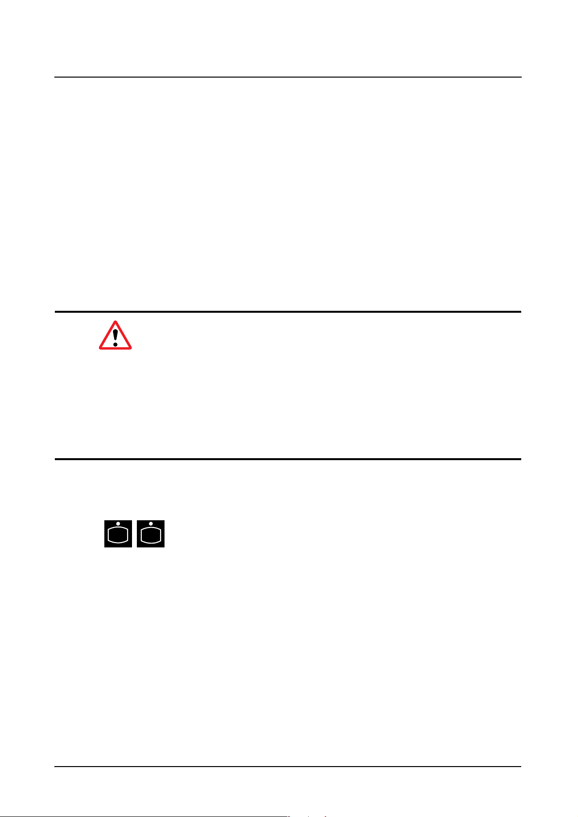
System Operation
Setting the Image Geometry
Additional Cu filter
The organ programs determine which additional Cu filter is moved into the beam
path on selection of the program.
A temporary change of the automatic additional Cu filter selection with organ program is possible by manual switchover. The manually selected additional Cu filter
is maintained until renewed switchover or selection of an organ program with
configured additional Cu filter.
The currently selected additional Cu filter is displayed on the control units and primary collimator.
Image reversal
Warning
R
It is part of the user’s duty to pay attention to the correct
orientation of the display on the monitor. Use suitable aids for this,
e.g. Pb letters.
Electronically displayed right/left markings are not mirrored when the image is
reversed.
A faulty diagnosis is possible due to incorrect position information, e.g. confusion between right and left, with legal consequences and under certain circumstances with severe consequences for the patient.
You can mirror the images on the image monitor horizontally or vertically with
these 2 keys. If none of the keys is pressed, then the image is displayed in the
normal position.
Image mirrored horizontally / vertically
R
30 / 32 AXD3-340.620.13.01.02 Operator Manual
Page 83

System Operation
Setting the Image Geometry
Switching over the image intensifier format
You can switch over the format even during a current examination.
◆ Press one of the keys.
– LED lights up: the function is selected.
Image intensifier full format
Zoom level 1, 2, 3
1
2
3
Regularly control the function of the format switch over!
➩ Refer to the maintenance plan.
AXIOM Iconos R200 AXD3-340.620.13.01.02 31 / 32
Page 84

System Operation
Setting the Image Geometry
32 / 32 AXD3-340.620.13.01.02 Operator Manual
Page 85

Examination
Table of Contents
Operator Manual
Examination
Chapter: Transferring and Positioning the Patient
General information ............................................................................................................5
Positioning the patient ........................................................................................................5
Chapter: Fluoroscopy
Fluoroscopy operating modes ............................................................................................ 7
Selecting the fluoroscopy operating mode ......................................................................... 7
Changing the selection of the fluoroscopy operating mode ............................................... 7
Fluoroscopy with Supervision (optional) ............................................................................... 8
Pulsed fluoroscopy (optional) ............................................................................................. 8
Roadmap ...................................................................................................................... 8
Releasing fluoroscopy ........................................................................................................ 9
Fluoroscopic data ............................................................................................................... 9
Display of the kV and mA values ........................................................................................ 9
Display of the fluoroscopic time ......................................................................................... 9
Display of the area dose product (optional) ........................................................................... 9
Resetting the fluoroscopic data ........................................................................................ 10
Automatic fluoroscopic control ......................................................................................... 10
Selecting automatic fluoroscopic control ............................................................................ 10
Stop function ............................................................................................................... 10
Fluoroscopic curves ....................................................................................................... 10
Fluoroscopy time limit ...................................................................................................... 11
Fluoroscopy warning signal .............................................................................................. 11
Automatic format collimation in fluoroscopy .................................................................... 11
Fluoroscopy programs ...................................................................................................... 11
Dose reduction .................................................................................................................12
AXIOM Iconos R200 AXD3-340.620.13.01.02 1 / 52
Page 86

Examination
Table of Contents
Chapter: Cassette Exposures in the Spotfilm Device (optional)
Automatic format collimation in radiography .................................................................... 13
Bucky mode ................................................................................................................. 13
Semiautomatic mode ..................................................................................................... 13
Fully automatic mode ..................................................................................................... 13
Cassette program ............................................................................................................. 14
Cassette formats and segmentation program ..................................................................... 14
Selecting the segmentation program ................................................................................. 14
Format segmentation ..................................................................................................... 15
Skipping a segmentation segment ........................................................................... 15
Mixed mode ........................................................................................................ 15
Loading / unloading the spotfilm device ........................................................................... 16
Loading ....................................................................................................................... 16
Unloading .................................................................................................................... 17
Exposure measurement for cassette exposures .............................................................. 17
Arrangement of the dominants ........................................................................................ 17
Selection of the dominants ............................................................................................. 18
Releasing the exposure .................................................................................................... 19
Organ programs ................................................................................................................ 19
Single exposures / serialography ...................................................................................... 19
Single exposure ............................................................................................................ 19
Serialography ............................................................................................................... 20
Bucky mode ...................................................................................................................... 20
Spotfilming without tomography ...................................................................................... 20
Tomography (optional) ...................................................................................................... 21
Tomographic sequence .................................................................................................. 22
Chapter: Digital Radiography
Automatic format collimation in digital radio-graphy ......................................................... 23
Exposure measurement in digital radiography ................................................................. 23
Arrangement of the dominants ........................................................................................ 23
Selecting the dominants ................................................................................................. 24
2 / 52 AXD3-340.620.13.01.02 Operator Manual
Page 87

Examination
Table of Contents
Spotfilming without tomography ...................................................................................... 25
Selection ..................................................................................................................... 25
Single image - serialography ............................................................................................ 25
Changing selection ............................................................................................... 25
Frame rate .......................................................................................................... 25
Releasing the exposure .................................................................................................. 26
Organ programs ............................................................................................................ 26
Programs ............................................................................................................ 27
Creation of programs ............................................................................................ 27
Temporary changes of programs ............................................................................. 27
Tomography (optional) ...................................................................................................... 27
Selection ..................................................................................................................... 27
Tomographic sequence .................................................................................................. 28
Releasing the exposure .................................................................................................. 29
Organ programs ............................................................................................................ 29
Programs ............................................................................................................ 29
Creation of programs ............................................................................................ 29
Temporary changes of programs ............................................................................. 29
Periscanning ..................................................................................................................... 30
General ....................................................................................................................... 30
Selection ..................................................................................................................... 30
Deselection ................................................................................................................. 30
Releasing the exposure .................................................................................................. 31
Examination procedure ................................................................................................... 31
Preparation ......................................................................................................... 31
Test run .............................................................................................................. 32
Scanning process ................................................................................................. 33
End of the scene .................................................................................................. 33
Organ programs ............................................................................................................ 33
Creation of programs ............................................................................................ 33
Temporary changes of programs ............................................................................. 33
Peristepping (optional) ...................................................................................................... 34
General ....................................................................................................................... 34
Programming run ................................................................................................. 35
Filling run ............................................................................................................ 35
Selection ..................................................................................................................... 35
Deselection ................................................................................................................. 35
Releasing an exposure ................................................................................................... 36
Examination procedure ................................................................................................... 36
Preparation ......................................................................................................... 36
Programming run ................................................................................................. 38
Filling run ............................................................................................................ 39
End of scene ....................................................................................................... 39
Organ programs ............................................................................................................ 40
Creation of programs ............................................................................................ 40
Temporary changes of programs ............................................................................. 40
AXIOM Iconos R200 AXD3-340.620.13.01.02 3 / 52
Page 88

Examination
Table of Contents
DR-Scanning (optional) ..................................................................................................... 40
General ....................................................................................................................... 40
Selection ..................................................................................................................... 41
Deselection ................................................................................................................. 41
Image transfer .............................................................................................................. 41
Releasing an exposure ................................................................................................... 41
Examination procedure for abdominal survey images ........................................................... 42
Preparation ......................................................................................................... 42
Moving the system and tabletop into the starting position ............................................ 43
Scanning process ................................................................................................. 43
End of the scene .................................................................................................. 43
Examination procedure for images of the spine and orthopedic longleg images ......................... 44
Preparation ......................................................................................................... 44
Moving the system and tabletop into the starting position ............................................ 45
Scanning process ................................................................................................. 45
End of the scene .................................................................................................. 45
Organ programs ............................................................................................................ 46
Program suggestions for FLUOROSPOT Compact ...................................................... 46
Peristepping examination sequence for survey images ......................................................... 47
Chapter: Free Cassette Exposure
Collimation on exposure ................................................................................................... 49
Selecting the exposure technique .................................................................................... 49
Tabletop cassette exposure or free mode .......................................................................... 49
Releasing an exposure ..................................................................................................... 50
Chapter: Cassette exposures with wall stand
Collimation during exposure ............................................................................................. 51
Selecting the exposure technique .................................................................................... 51
Releasing the exposure .................................................................................................... 52
4 / 52 AXD3-340.620.13.01.02 Operator Manual
Page 89
Examination
Transferring and Positioning the Patient
General information
❏ Attach all safety accessories, especially the grip protection strip, handgrip
strip, handgrip, footboard and shoulder supports.
❏ Use only positioning aids expressly approved by Siemens. Contact your local
Siemens representative if you have any questions.
❏ Refer to the ”Accessories” Register for all accessories available for position-
ing. Attaching the accessories is also described there.
❏ Ensure that these devices and positioning aids are secured correctly and are
functioning properly.
❏ Make sure that the body parts of the patient, especially arms and legs, do not
extend over the edge of the tabletop.
❏ Ensure that the patient uses the grip locations provided.
Positioning the patient
So that you can position the patient comfortably,
◆ Press this key, the system moves into a position favorable for patient transfer.
◆ Now transfer the patient.
◆ Immobilize the patient with the corresponding accessory parts.
◆ Move the radiographic system into the required position.
Warning
The collision protection system does not recognize accessory parts which
project beyond the system contours.
The system and the accessories can be damaged and possibly the patient can
also be injured.
AXIOM Iconos R200 AXD3-340.620.13.01.02 5 / 52
Page 90

Examination
Transferring and Positioning the Patient
6 / 52 AXD3-340.620.13.01.02 Operator Manual
Page 91

Examination
Fluoroscopy
Fluoroscopy operating modes
❏ Standard fluoroscopy (continuous fluoroscopy)
– In continuous fluoroscopy 30 (25)
television central control unit.
❏ Fluoroscopy with pulsed television scanning (Supervision option)
– In SUPERVISION only 15 (12.5)
case fluoroscopy is applied at half the radiation dose with half the temporal
resolution.
or
❏ Primary pulsed fluoroscopy (CAREVISION option)
– In pulsed fluoroscopy, the radiation is pulsed at 15 (12.5)
1
(3)
pulses per second. In this way a corresponding dose saving with a
lower temporal resolution is possible.
1
frames per second are generated by the
1
frames per second are generated. In this
1
or 7.5 (8.3)1 or 3
❏ Roadmap (only with DSA option) with standard fluoroscopy, with Supervision
(optional) or pulsed fluoroscopy (optional)
– Roadmap is a special fluoroscopic mode with subtraction display
Selecting the fluoroscopy operating mode
All parameters necessary for fluoroscopy are stored in organ programs.
◆ Select a corresponding organ program on the integrated generator control
console.
Changing the selection of the fluoroscopy operating mode
It is possible to change the selection of the operating modes in connection with
the Supervision or CAREVISION options.
The current operating mode is displayed in the operating menu of the live monitor.
Use the FLUOROSPOT Compact infrared control for operation.
If your system is equipped only with standard fluoroscopy, the Fluoro+ and Fluoro- keys have no function.
1
Values in brackets apply to VIDEOMED DHC
AXIOM Iconos R200 AXD3-340.620.13.01.02 7 / 52
Page 92

Examination
Fluoroscopy
Fluoroscopy with Supervision (optional)
◆ By pressing one of the keys you select
Fluoro
+
Fluoro
+
Fluoro
-
Fluoro
-
Standard fluoroscopy (Fluoro +) or Supervision (Fluoro -)
You can also switch from one operating mode to another during a fluoroscopic
examination.
Pulsed fluoroscopy (optional)
◆ Press one of the keys briefly to selected
– Pulsed fluoroscopy with a pulse rate of 3 (3)
or 15 (12.5)
1
p/s or
– Standard fluoroscopy.
Increase (Fluoro+) / decrease (Fluoro-) the pulse rate
A pulse rate of 3 p/s is the lowest setting and standard fluoroscopy is the highest
setting.
You can also switch over from one operating mode to another during fluoroscopy.
1
p/s, 7.5 (8.3)1 p/s
Road-
map
Roadmap
2
Roadmap can be combined with all fluoroscopic modes. There is a corresponding
Roadmap Fluoro program for every combination.
◆ Press this key to select/deselect Roadmap.
You can select/deselect this function only when radiation is not being released.
Roadmap is automatically deselected when you change to the “Pat. List“ menu,
on changing the exposure system (Peri, bed-side exposure) or the organ program selection.
➩ Refer to the FLUOROSPOT Compact Operator Manual for information on the
operating sequence.
1
Values in brackets apply to VIDEOMED DHC
2
only with DSA option
8 / 52 AXD3-340.620.13.01.02 Operator Manual
Page 93

Examination
Fluoroscopy
Releasing fluoroscopy
❏ Use the foot switch to release fluoroscopy.
❏ Radiation is released as long as you continue to press the footswitch for fluo-
roscopy. After you let the switch go, the last image is retained and displayed
on the monitor (LIH).
❏ With the red emergency STOP button actuated, fluoroscopy can be switched
back on consciously after letting the fluoroscopy switch go and pressing it
again.
❏ A patient folder must be created and selected in the FLUOROSPOT Compact.
❏ No processing functions apart from storing the image are possible during flu-
oroscopy.
❏ The radiation ON indicators must light up.
Warning
If these radiation ON indicators light up although no switch has been actuated
and the current fluoroscopic image cannot be seen on the monitor:
◆ Switch the system off immediately!
◆ Notify the SIEMENS Uptime Service.
◆ Discontinue use of the system.
Fluoroscopic data
The fluoroscopic data of kV, mA, time and area dose product (optional) are displayed on the integrated generator control console.
Display of the kV and mA values
❏ During fluoroscopy:
– Running display of the momentary kV and mA values
❏ After the end of fluoroscopy:
– kV and mA mean value of the examination
Display of the fluoroscopic time
Continuous display of the time accumulating in the examination in minutes.
Display of the area dose product (optional)
Continuous display of the area dose product accumulating in the examination.
AXIOM Iconos R200 AXD3-340.620.13.01.02 9 / 52
Page 94

Examination
Fluoroscopy
Resetting the fluoroscopic data
Once the examination is ended, then please note the displayed fluoroscopic data
and
◆ Press the reset key.
– The displays for the fluoroscopic data and the area dose product are reset
to zero.
Automatic fluoroscopic control
Selecting automatic fluoroscopic control
The fluoroscopic curves and dose levels preset in the organ program can be
changed with the automatic program keys on the system remote control console.
You can select different fluoroscopic curves with the automatic programs.
◆ You select automatic programs 1, 2 or 3 with one of the keys.
1
2
3
Stop function
If the fluoroscopic values (kV, mA) set by the system should remain constant
◆ Press the stop key during fluoroscopy.
If you want to cancel the stop function
◆ Select one of the 3 automatic programs by a key or an organ program.
Fluoroscopic curves
Depending upon the system configuration, the following fluoroscopic curves are
assigned to the automatic programs:
Automatic
program
Configured with
standard Fluoro
Configured with
standard Fluoro
and SUPERVISION
Configured with
standard Fluoro
and CAREVISION
1 Dose-reduced curve Antiisowatt curve
2 Antiisowatt curve
3 Contrast curve (60 to 80 kV)
10 / 52 AXD3-340.620.13.01.02 Operator Manual
Page 95

Fluoroscopy time limit
Examination
Fluoroscopy
Fluoroscopy is switched off automatically and can no longer be switched on after
a fluoroscopy time of 10 minutes
To continue working
◆ let the fluoroscopy switch go and press it once again.
1
.
Fluoroscopy warning signal
An acoustic signal sounds after a fluoroscopy time of maximum 5 minutes2.
◆ The signal disappears when you press the key on the Fluorospot Compact.
The time for the acoustic signal can be reset to zero at any time.
Automatic format collimation in fluoroscopy
Automatic format collimation is also switched on automatically when fluoroscopy
is released.
I.e. the fluoroscopic field is never larger than the selected image intensifier format.
You can limit the fluoroscopic field to the required size with the corresponding
operating elements within this area.
Fluoroscopy programs
All parameters necessary for fluoroscopy are stored in programs.
The following programs can be stored:
– Standard fluoroscopy
– Supervision
– Pulsed fluoroscopy (Carevision)
– Roadmap standard fluoroscopy
– Roadmap Supervision
– Roadmap pulsed fluoroscopy
➩ Refer to the Fluorospot Compact Operator Manual.
1
Can be changed on request by SIEMENS Uptime Service, under compliance with the national
regulations.
2
Can be configured from 1 to 5 minutes by the SIEMENS Uptime Service
AXIOM Iconos R200 AXD3-340.620.13.01.02 11 / 52
Page 96

Examination
Fluoroscopy
Dose reduction
In fluoroscopy with CAREVISION (pulsed fluoroscopy) or SUPERVISION the following dose reductions configured in the factory result related to standard fluoroscopy:
Automatikprogramm
1 - 50% - 75% - 90% - 50%
2- 33%
3 - 30% - 50% - 65% - 50%
*
Deviating factory setting for USA
CAREVISION
15 P/s
1
CAREVISION
7,5 P/s
*
- 55%* - 75%* - 50%
CAREVISION
3 P/s
SUPERVISION
1
for image receptor input dose rate
12 / 52 AXD3-340.620.13.01.02 Operator Manual
Page 97

Examination
Cassette Exposures in the Spotfilm Device (optional)
Automatic format collimation in radiography
Bucky mode
In the Bucky mode, the rectangular diaphragms move to the format of the inserted cassette or to the selected segmentation format. The light localizer is
switched on automatically on selection. The radiation field can then be collimated
smaller as desired. The collimation is retained during the exposure.
Bucky mode is active: LED lights up
Semiautomatic mode
In the semiautomatic mode, the rectangular diaphragms are limited automatically
to the cassette or segmentation format. It is possible to collimate arbitrarily within
the cassette or segmentation format. The collimation is retained during the exposure.
Semiautomatic mode is active: no LED lights up.
Fully automatic mode
In the fully automatic mode, the rectangular diaphragms are limited automatically
to the cassette or segmentation format. It is possible to collimate arbitrarily within
the cassette or segmentation format.
If the rectangular diaphragms are opened less than the cassette or segmentation
format, then they are opened up to the selected cassette or segmentation format
during the preparation.
Automatic format collimation can also be selected separately for height and width
diaphragms. The diaphragms not selected then behave in the same way as with
semiautomatic mode.
Fully automatic mode width and height is active: both LEDs light up.
Fully automatic mode width is active: right LED lights up; left LED is dark..
Fully automatic mode height is active: right LED is dark; left LED lights up..
AXIOM Iconos R200 AXD3-340.620.13.01.02 13 / 52
Page 98

Examination
Cassette Exposures in the Spotfilm Device (optional)
Cassette program
Cassette formats and segmentation program
The following cassettes standardized according to IEC, ANSI or DIN are permitted:
Full format (1 on 1) 2 on 1 3 on 1 4 on 1
18 cm x 24 cm
8" x 10"
20 cm x 40 cm
24 cm x 24 cm
9,5" x 9,5"
24 cm x 30 cm
10" x 12"
30 cm x 35 cm
11" x 14"
30 cm x 40 cm
35 cm x 35 cm
14" x 14"
35 cm x 43 cm
14" x 17"
40 cm x 40 cm
Selecting the segmentation program
◆ Select the spotfilm device exposure technique at the system remote control
console.
◆ Insert an approved cassette in the spotfilm device.
◆ Select the required segmentation program by pressing one of the keys.
– The LED in the pressed key lights up.
– The number of free exposures is displayed in the display.
14 / 52 AXD3-340.620.13.01.02 Operator Manual
Page 99

Examination
Cassette Exposures in the Spotfilm Device (optional)
Full format (no segmentation)
Segmentation 2 on 1
Segmentation 3 on 1
Segmentation 4 on 1
If you have selected a segmentation program which cannot be obtained with the
inserted type of cassette, then the LEDs in the keys for the selected segmentation program flash.
If "0" is displayed in the display after the exposure, the selected program has
been completed.
Further exposures are then blocked.
Format segmentation
Skipping a segmentation segment
◆ Press the selected segmentation key once again, if you wish to skip a segment during exposure.
Mixed mode
It is possible to change the segmentation within a cassette as long as the unexposed part of the cassette permits the newly selected segmentation.
AXIOM Iconos R200 AXD3-340.620.13.01.02 15 / 52
Page 100

Examination
Cassette Exposures in the Spotfilm Device (optional)
Loading / unloading the spotfilm device
Warning
Risk of injury during automatic cassette size sensing!
◆ Do not reach into the loading shaft of the spotfilm device.
Loading
LED lights up: Cassette in unloading position.
◆ Insert the cassette with the smooth side upwards and insert at least 2/3 of the
cassette width into the loading shaft.
– The cassette is drawn in automatically and parked in the spotfilm device.
– At the same time the cassette format is measured and the LED in the cor-
responding segmentation key lights up.
– The cassette size is shown in the display of the system remote control con-
sole.
If a cassette format which is not approved is used, the cassette moves automatically back into the loading position.
The cassette does not appear in the loading slot:
◆ Tilt the tabletop into the +45° position.
◆ Press the unloading key briefly a number of times until the cassette appears
in the loading slot.
In a table position of approx. 45° to 90° it can happen that if the cassette is not
inserted far enough it drops out from the loading shaft again on automatic centering depending on its make/type. The formats 20 x 40 cm, 18 x 24 cm and
24 x 30 cm inserted in upright format are especially affected by this.
In this case,
◆ insert the cassette with its smooth side upwards and with at least 3/4 of the
cassette width in the loading slot
◆ hold the ball of your thumb against the cassette until it is securely grasped by
the cassette jaws.
Caution
Under no circumstances may you poke your fingers into the loading slot as this
would interrupt the sensing light barrier. Otherwise the cassette is rejected.
16 / 52 AXD3-340.620.13.01.02 Operator Manual
 Loading...