

Page 1
Release 1.0
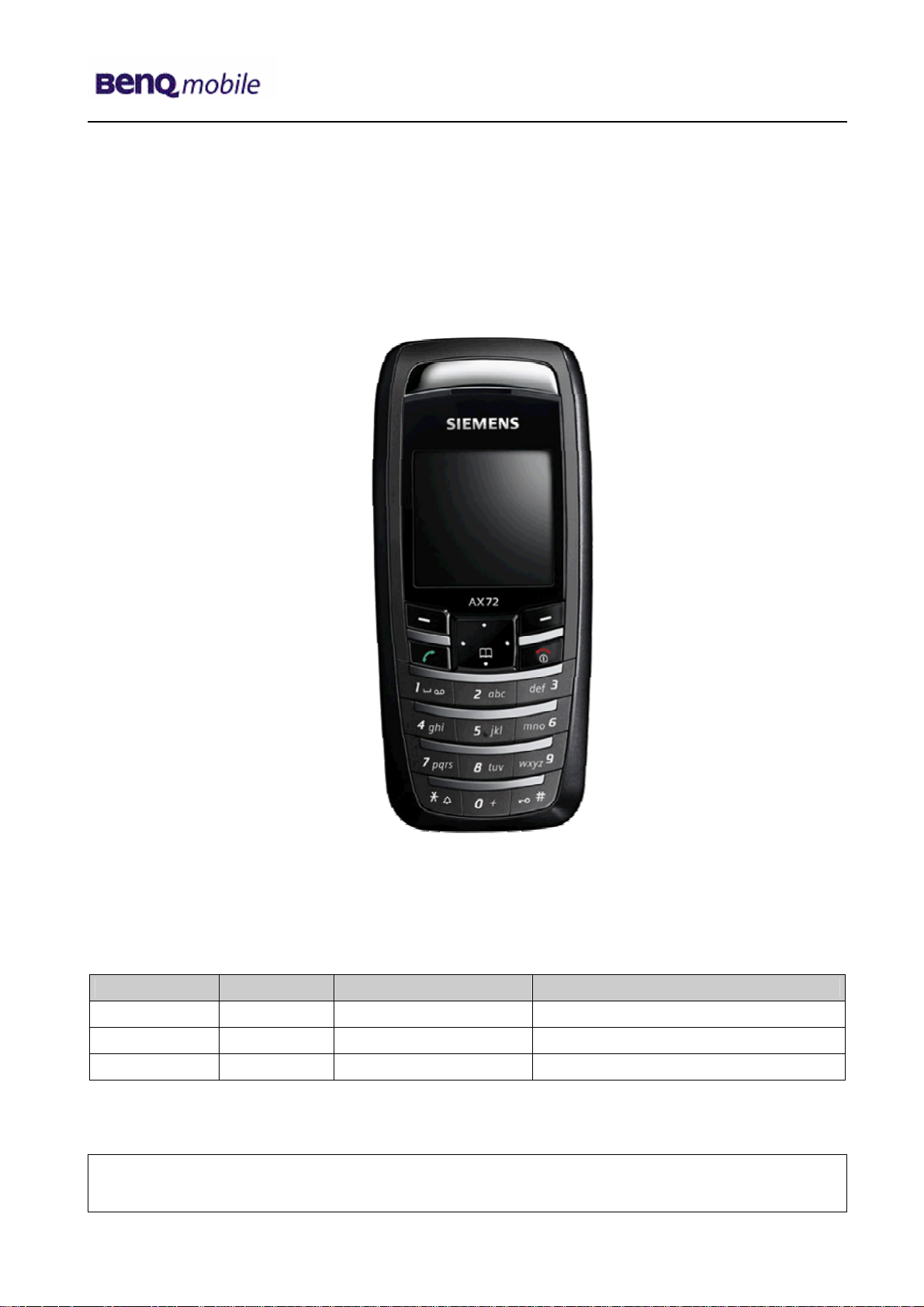
Service Repair Documentation
Level 3 – AX72
Release Date Department Notes to change
R 1.0 28.11.2005 BenQ MD CC S CES New document
Technical Documentation 10/2005
TD_Repair_L3_AX72_R1.0.pdf Page 1 of 11
Company Confidential
2005©BenQ
Page 2
Release 1.0
Table of Content
1 Introduction ...............................................................................................................................3
1.1 PURPOSE ...............................................................................................................................3
1.2 SCOPE ...................................................................................................................................3
1.3 TERMS AND ABBREVIATIONS ...................................................................................................3
2 List of available level 3 parts....................................................................................................4
3 Hardware requirements ............................................................................................................4
4 AX72 Board layout ....................................................................................................................5
5 SIM Card Problems ...................................................................................................................6
6 IO Connector Problems ............................................................................................................7
7 LED_Keypad illumination Problems........................................................................................8
8 Battery Connector Problems.................................................................................................... 9
9 Display Problems ....................................................................................................................10
10 IRDA Problems ........................................................................................................................11
Technical Documentation 10/2005
TD_Repair_L3_AX72_R1.0.pdf Page 2 of 11
Company Confidential
2005©BenQ
Page 3
Release 1.0
1 Introduction
1.1 Purpose
This Service Repair Documentation is intended to support Service partners to carry out repairs on
BenQ repair level 3. The described failures shall only be repaired in BenQ authorized local
workshops.
The level 3 (former Level 2.5light) partners are obliged to repair level 3 classified boards, up to their
repair level, under consideration of this repair instruction.
All repairs have to be carried out in an ESD protected environment and with ESD protected
equipment/tools. For all activities the international ESD regulations have to be considered.
Assembling/disassembling has to be done according to the latest AX72 Level 1-2 repair
documentation. It has to be ensured that every repaired mobile Phone is checked according to the
latest released General Test Instruction document (both documents are available in the Technical
Support section of the C-market).
Check at least weekly C-market for updates and consider all AX72 related Customer Care
Information
AX72 Partnumber on IMEI label: S30880-S2860-#xxx
, while # may be any letter (A-Z) and xxx may be any number from 100, 101, 102....
Scrap Handling: All Scrap information given in this manual are related to the
SCRAP-Rules and instructions.
Attention: Consider the new "LEAD-FREE" soldering rules (available in the communication
market), avoid excessive heat.
1.2 Scope
This document is the reference document for all BenQ authorised Service Partners which are
released to repair BenQ mobile phones up to level 3.
1.3 Terms and Abbreviations
Technical Documentation 10/2005
TD_Repair_L3_AX72_R1.0.pdf Page 3 of 11
Company Confidential
2005©BenQ
Page 4
Release 1.0
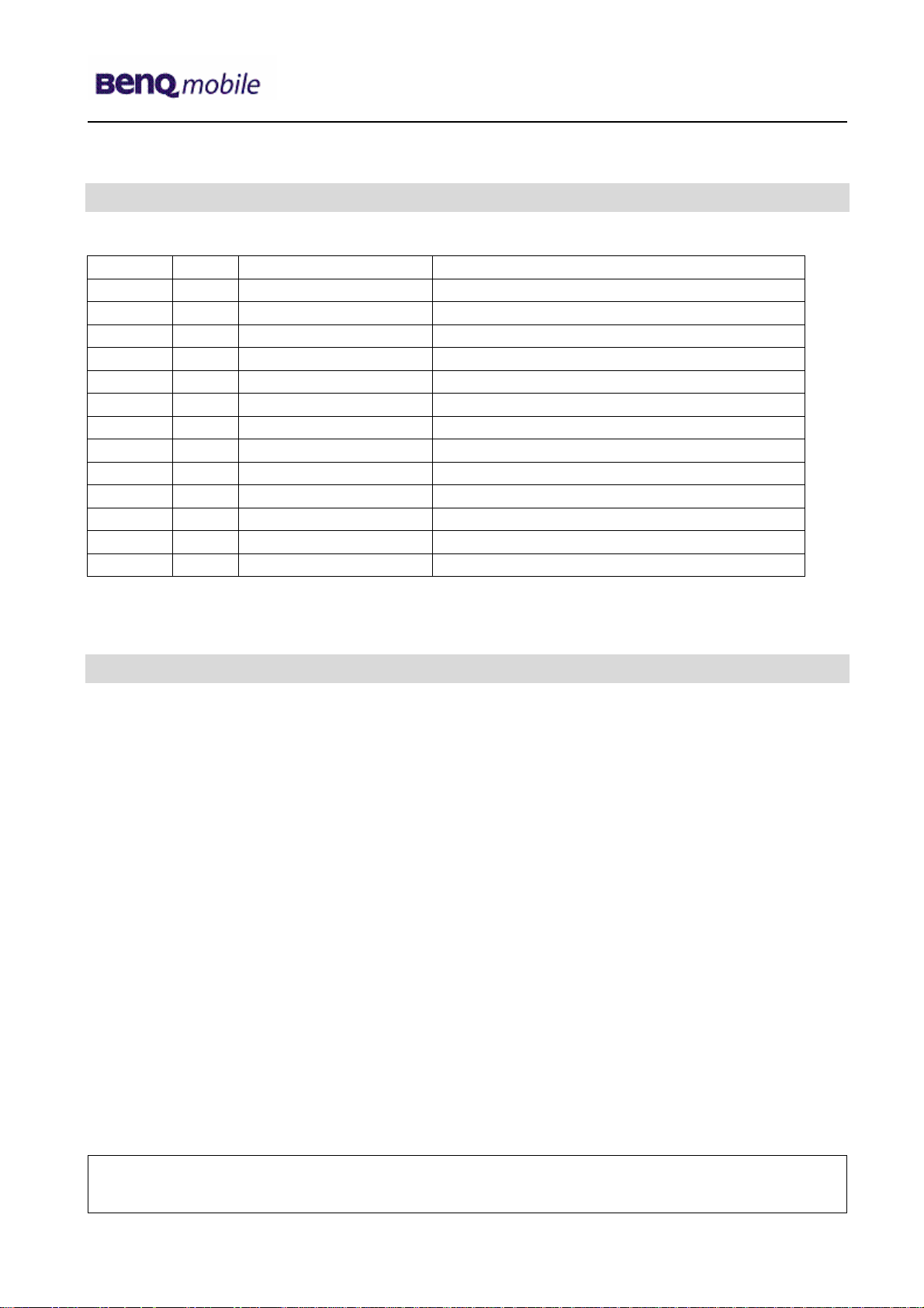
2 List of available level 3 parts
(according to Component Matrix V1.09 - check C-market for updates)
Product ID Order Number Description CM
AX72 C1605 L36853-C6224-M6 CAPACITOR 2220N (Cap-Type3)
AX72 R1614 L50652-C472-J2 RESISTOR 4K7 (Res-Type11)
AX72 V286 L36840-L2056-D670 LED AMBER
AX72 V287 L36840-L2056-D670 LED AMBER
AX72 V288 L36840-L2056-D670 LED AMBER
AX72 V289 L36840-L2056-D670 LED AMBER
AX72 V290 L36840-L2056-D670 LED AMBER
AX72 V291 L36840-L2056-D670 LED AMBER
AX72 X1400 L36334-Z97-C213 CONNECTOR BATTERY 3-POL
AX72 X1603 L36334-Z97-C337 CONNECTOR SIM CARD READER K1
AX72 X211 L36334-Z93-C303 IO-JACK SLIM 12-POL
AX72 X2202 L36334-Z97-C205 CONNECTOR DISPLAY 10POL
AX72 Z1601 L50620-U6029-D670 FILTER EMI (Fi-Type6) PB Free
3 Hardware requirements
(according to L2.5L-L2.5 General soldering information V1.3 - check C-market for updates)
Jigs, Tools and working materials for all described repairs:
hot air blower
soldering gun
tweezers
flux
solder
Technical Documentation 10/2005
TD_Repair_L3_AX72_R1.0.pdf Page 4 of 11
Company Confidential
2005©BenQ
Page 5

Release 1.0
4 AX72 Board layout
Upper board side
Lower board side
LED´s
IO-Slim
Connector SIM
Card Reader
Connector
Battery
Capacitor,
Resistor, Filter
Connector
Display
IRDA
Technical Documentation 10/2005
TD_Repair_L3_AX72_R1.0.pdf Page 5 of 11
Company Confidential
2005©BenQ
Page 6

Release 1.0
y
r
y
y
5 SIM Card Problems
Fault Symptoms
Customer: GRT:
Handset does not accept SIM card SIM Card Problems
SIM Card Problems
Watch for oxidation and
damaged pads of the
SIM Card reader
okay
Check the status of the
EMI Filter visually
Exchange
SIM Card reade
not
oka
not
oka
Check the status of the
SIM Card reader visually
Use the resistor test
function of a multimeter
to check connection
between spring
contacts and soldering
contacts.
The value must be ~0Ω
okay
okay
Connector SIM Card Reader
Use soldering iron to remove defective component. Avoid excessive heat! Watch surrounding components!
Resolder new component afterwards.
E-commerce order number: L36334-Z97-C337
E-commerce order name: CONNECTOR SIM CARD READER K1
Soldering temperature: ~ 360°C Tip Temp.
IRIS Diagnose Code: 43300 Interface/SIM Cardreader/Mechanical Damage
not
oka
okay
Back to customer
without repair
caused by customer
SCRAP - has to be send
separately to WSC
Exchange the
damaged Filter
- check for twisted or
bent contacts
- check for dry joints
Continue with
higher repair level
Technical Documentation 10/2005
TD_Repair_L3_AX72_R1.0.pdf Page 6 of 11
Company Confidential
2005©BenQ
Page 7

Release 1.0
y
r
y
y
6 IO Connector Problems
Fault Symptoms
Customer: GRT:
Charging Problems No connection to GRT
Problems with external loudspeaker or microphone when using
a car kit
Problems with accessories connected at the IO connector
IO connector Problems
Watch for oxidation and
damaged pads of the
IO connector
okay
not
oka
not
oka
Check the dust inside
the IO connector
okay
Check the status of the
IO connector visually
okay
Exchange
IO connecto
not
oka
Use the resistor test
function of a multimeter
to check connection
between spring
contacts and soldering
contacts.
The value must be ~0Ω
okay
Connector IO Jack
Use soldering iron to remove defective component. Avoid excessive heat! Watch surrounding components!
Resolder new component afterwards.
E-commerce order number: L36334-Z93-C303
E-commerce order name: IO-JACK SLIM 12-POL
Soldering temperature: ~ 360°C Tip Temp.
IRIS Diagnose Code: 46100 Interface/Charging Connector/Mechanical Damage
47300 Interface/Data Interface/Mechanical Damage
4B100 Interface/Headset Connector/Mechanical Damage
Back to customer
without repair
caused by customer
SCRAP - has to be send
separately to WSC
Clean IO connector
- check for twisted or
bent contacts
- check for dry joints
Continue with
higher repair level
Technical Documentation 10/2005
TD_Repair_L3_AX72_R1.0.pdf Page 7 of 11
Company Confidential
2005©BenQ
Page 8

Release 1.0
y
y
7 LED_Keypad illumination Problems
okay
Back to customer
without repair
caused by customer
SCRAP - has to be send
separately to WSC
- check for twisted or
bent contacts
- check for dry joints
Continue with
higher repair level
Fault Symptoms
Customer: GRT:
Main keypad illumination does not work Current measured failed
Led’s Problems
Watch for oxidation and
damaged pads of the
LED’s
okay
not
oka
Check the status of the
LED’s visually
Exchange
keypad LED’s
not
oka
Use the diode test
function of a multimeter
to check the status of
the diode. The typical
voltage drop on the
diode is 1.7 V when
testing the diode
function with the
multimeter.
LED_ KEYPAD
Remove metal dome sheet before replace LED’s Use soldering iron to remove defective component. Avoid
excessive heat! Watch surrounding components! Resolder new component afterwards. The metal dome jip
must be used to place the metal dome sheet.
E-commerce order number: L36840-L2056-D670
E-commerce order name: LED AMBER
Soldering temperature: ~ 360°C Tip Temp.
IRIS Diagnose Code: 22000 Display / Background Illumination
Technical Documentation 10/2005
TD_Repair_L3_AX72_R1.0.pdf Page 8 of 11
Company Confidential
2005©BenQ
Page 9

Release 1.0
y
y
8 Battery Connector Problems
okay
Back to customer
without repair
caused by customer
SCRAP - has to be send
separately to WSC
- check for twisted or
bent contacts
- check for dry joints
Continue with
higher repair level
Fault Symptoms
Customer: GRT:
Mobile does not switch on Current measured failed
Battery connector
Problems
Watch for oxidation and
damaged pads of the
Connector
okay
not
oka
Check the status of the
Connector visually
Exchange
Battery
Connector
not
oka
Use the resistor test
function of a
multimeter to check
connection between
spring contacts and
soldering contacts.
The value must be
~0Ω
Connector BATTERY
Use hot air blower to remove defective component. Avoid excessive heat! Watch surrounding components!
Resolder new component afterwards.
E-commerce order number: L36334-Z97-C213
E-commerce order name: CONNECTOR BATTERY 3-POL
Soldering temperature: ~ 360°C Tip Temp.
IRIS Diagnose Code: 13000 Battery/Mechanical Damage
Technical Documentation 10/2005
TD_Repair_L3_AX72_R1.0.pdf Page 9 of 11
Company Confidential
2005©BenQ
Page 10

Release 1.0
y
y
9 Display Problems
Fault Symptoms
Customer: GRT:
Display problems, like missing lines or columns on the LCD
or display contrast problems or illumination problems
Display connector
Problems
Watch for oxidation and
damaged pads of the
Connector
okay
not
oka
Check the status of the
Connector visually
Exchange
Display
Connector
not
oka
Use the resistor test
function of a
multimeter to check
connection between
spring contacts and
soldering contacts.
The value must be
~0Ω
Connector DISPLAY
Use hot air blower to remove defective component. Avoid excessive heat! Watch surrounding components!
Resolder new component afterwards.
E-commerce order number: L36334-Z97-C205
E-commerce order name: CONNECTOR DISPLAY 10POL
Soldering temperature: ~ 360°C Tip Temp.
IRIS Diagnose Code: 21000 Display / Performance
22000 Display / Background Illumination
Display problems
caused by customer
SCRAP - has to be send
separately to WSC
- check for twisted or
bent contacts
- check for dry joints
okay
higher repair level
Back to customer
without repair
Continue with
Technical Documentation 10/2005
TD_Repair_L3_AX72_R1.0.pdf Page 10 of 11
Company Confidential
2005©BenQ
Page 11

Release 1.0
y
10 IRDA Problems
Not
oka
Back to customer
without repair
caused by customer
SCRAP - has to be send
separately to WSC
- Check for dry joints
Change IRDA
settings
Fault Symptoms
Customer: GRT:
IRDA does not work Display problems
IRDA Problems
Watch for oxidation and
damaged pads of the
Diode
okay
not
okay
Check the status of the
Diode visually
Exchange
IRDA Diode
okay
Check the settings in
the phone menu.
Connector DISPLAY
Use hot air blower to remove defective component. Avoid excessive heat! Watch surrounding components!
Resolder new component afterwards.
E-commerce order number: L36334-Z97-C205
E-commerce order name: CONNECTOR DISPLAY 10POL
Soldering temperature: ~ 360°C Tip Temp.
IRIS Diagnose Code: 21000 Display / Performance
22000 Display / Background Illumination
Technical Documentation 10/2005
TD_Repair_L3_AX72_R1.0.pdf Page 11 of 11
Company Confidential
2005©BenQ
 Loading...