

Page 1

BIANGULIX / OPTILIX
AX
Installation and Setting Instructions
Also for: OPTITOP
© Siemens AG 1994
Not for:
OPTILIX 154/30/50R-100
Register 3 English
Print No.: R71-020.033.04.05.02 Doc. Gen. Date: 08.97
Replaces: R71-020.033.04.04.02
The reproduction, transmission or
use of this document or its contents
is not permitted without express
written authority. Offenders will be
liable for damages. All rights,
including rights created by patent
grant or registration of a utility
model _or_ design,_are_ reserved.
Page 2

0 - 2 Revision
Chapter Page Revision
0all03
1all03
2all03
3all03
4all01
0all04
1all04
2all04
3all04
4all02
0all05
2all05
4all03
BIANGULIX / OPTILIX Register 3 R71-020.033.04 Page 2 of 4 Siemens AG
Rev. 05 08.97 TD SD 31 Medical Engineering
Page 3

Contents 0 - 3
Page
1 _______Prerequisites __________________________________________________1 - 1
Safety and protective measures. . . . . . . . . . . . . . . . . . . . . . . . . . . . . 1 - 1
General information . . . . . . . . . . . . . . . . . . . . . . . . . . . . . . . . . . . 1 - 1
Mounting the x-ray tube assembly . . . . . . . . . . . . . . . . . . . . . . . . . . . 1 - 2
2 _______Installation ____________________________________________________2 - 1
Connection to the tube assembly (on the stator side). . . . . . . . . . . . . . . . . . 2 - 1
Stator connection . . . . . . . . . . . . . . . . . . . . . . . . . . . . . . . . . . . . 2 - 2
Protective earthing . . . . . . . . . . . . . . . . . . . . . . . . . . . . . . . . . . . 2 - 2
LOADIX connection . . . . . . . . . . . . . . . . . . . . . . . . . . . . . . . . . . . 2 - 3
Temperature limit value switch . . . . . . . . . . . . . . . . . . . . . . . . . . . . . 2 - 3
High-voltage connection. . . . . . . . . . . . . . . . . . . . . . . . . . . . . . . . . 2 - 4
Pre-filtering of the x-ray tube assembly . . . . . . . . . . . . . . . . . . . . . . . . . 2 - 5
Replacement of the additional filter . . . . . . . . . . . . . . . . . . . . . . . . . . . 2 - 5
I.I.-cone adaptati on . . . . . . . . . . . . . . . . . . . . . . . . . . . . . . . . . . . 2 - 7
Primary leaves. . . . . . . . . . . . . . . . . . . . . . . . . . . . . . . . . . . . . . 2 - 8
Useful radiation field. . . . . . . . . . . . . . . . . . . . . . . . . . . . . . . . . . . 2 - 9
3 _______Startup _______________________________________________________3 - 1
Startup of the tube assembly with high volt age . . . . . . . . . . . . . . . . . . . . . 3 - 1
Service notes . . . . . . . . . . . . . . . . . . . . . . . . . . . . . . . . . . . . . . 3 - 2
4 _______Changes to previous version_____________________________________4 - 1
Siemens AG Register 3 R71-020.033.04 Page 3 of 4 BIANGULIX / OPTILIX
Medical Engineering Rev. 05 08.97 TD SD 31
Page 4

0 - 4 Contents
This page intentionally left blank.
BIANGULIX / OPTILIX Register 3 R71-020.033.04 Page 4 of 4 Siemens AG
Rev. 05 08.97 TD SD 31 Medical Engineering
Page 5
Prerequisites 1
Safety and protective measures 1
• The safety notes and protective measures i n the corresponding generator documents
must be strictly observed.
General information 1
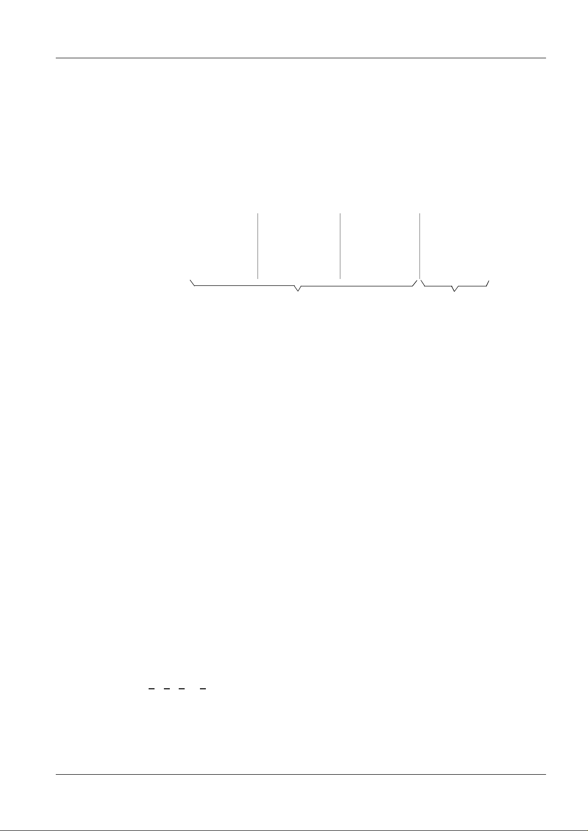
The tube housing with built-in x-ray tube i s called x-ray tube asse mbly. The desig nation of
the x-ray tube assembly comprises the following.
Example: Opti 150 / 40 / 82 C - 100L
kV small focus large focus
max. 150 kV max. 40 kW max. 80 kW
x-ray tube housing
Explanation of the Designations:
1 - 1
100: Housing for tubes with 100 mm anode.
Cable horns 90° to the radiation outlet
102: Housing for tubes with 100 mm anode.
Cable horns 40° to the radiation outlet
117: Housing for tubes with100 mm anode and
150 Hz - 300 Hz rotation,
Cable horns 90° to the radiation outlet
G: with 4-pole cathode plug connector
L: for LOADIX connection
OPTILIX tube assemblies without the designation ”L” (without LOADIX) are
equipped with 3-phase stators and can only be operated on generators with
starters that have been developed specifical ly for this.
These tube assemblies are shown with (3
ST: for stereo mode
C: CALOREX graphite anode
~ ) in the list.
HS: High-speed - 300 Hz rotation
R: Rapid 150 Hz rotation
/72/82/102: Anode mechanically stress-relieved
/52
The technical data of the tube assembly are supplied with the assembly.
Siemens AG Register 3 R71-020.033.04 Page 1 of 2 BIANGULIX / OPTILIX
Medical Engineering Rev. 04 12.96 TD SD 31
Page 6
1 - 2 Prerequisites
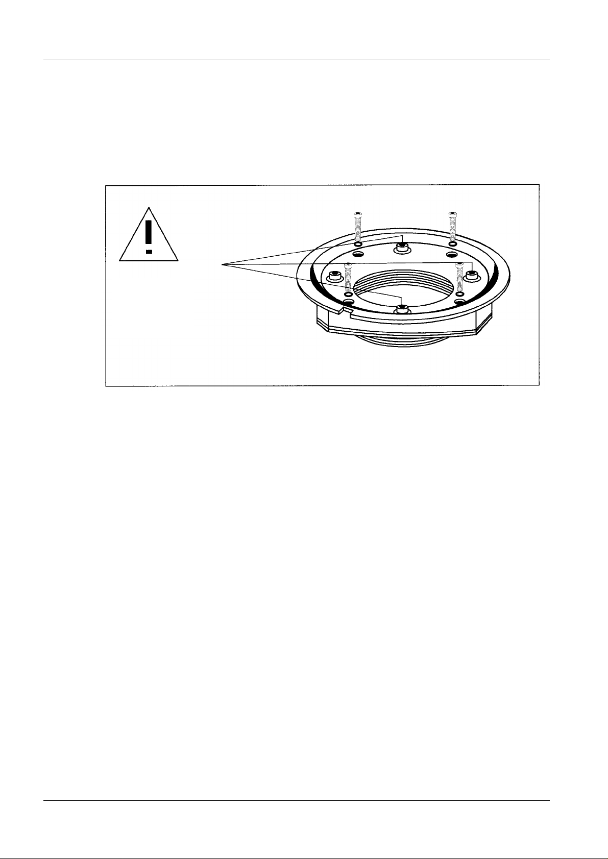
Mounting the x-ray tube assembly 1
The installation of the x-ray tube assembly to the unit is described in the corresponding
unit installation instr uctions.
Please observe especially the notes in the TI 376 (R71-020.038.03..., tube assembly
flange adjusted at the factory).
Do not loosen
screws secured
with varnish
BIANGULIX / OPTILIX Register 3 R71-020.033.04 Page 2 of 2 Siemens AG
Rev. 04 12.96 TD SD 31 Medical Engineering
Page 7

CAUTION
Installation 2
Fig. 1 Fig. 2
2 - 1
Connection to the tube assembly (on the stator side) 2
2-phase stator (Fig.1)
II, O, I Connection for rotating anode cable (4/Fig.1), see stator connection.
(insulate shielding - do not connect!)
Abweichende Angaben in den Generator Montageanleitungen sind zu
beachten.
3-phase stator (Fig.2)
Connection of the double-shielded rotati ng-anode cable on the tube assembly with
3-phase stator U
Controls
1, 2: LOADIX measured value acquisition (only for tube assemblies with
designation ”L”)
Jumper 1-2- (1/Fig.1) is removed for LOADIX mode.
The measuring resistor (2/Fig.1) is installed in the LOADIX
(see LOADIX installation and setting instructions R71-020.033.01...).
1, 2, 4: Connection of the oil pressure switch (5/Fig.1)
- Allocation with POLYDOROS: 2+1
- Allocation with PANDOROS: 1+4
= II, V1 = I, W1 = 0 (designation in the cover)
1
If the soldering connections for the oil pressure switch are
overheated, the plastic assembly can melt, which can adversely
affect the function of the switch.
Recommended soldering temperature: 350° C
Siemens AG Register 3 R71-020.033.04 Page 1 of 10 BIANGULIX / OPTILIX
Medical Engineering Rev. 05 08.97 TD SD 31
for max. 3 sec.
Page 8

2 - 2 Installation
CAUTION
NOTICE
Ground wire
Connection for
wire connection on the high-voltage generator.
≥ 6 mm
Stator connection 2
Use a cable 3 x 0,75 mm2 provided with shielding as stator cable.
2
ground wire (3/Fig.1) to the central ground
During the start-up phase, voltages o f
reason, use only shielded cables!
The shielded braiding of the stator cable is not
tube assembly side, except when the double-shielded rotatinganode cable is used, or in the case of other information specified
in the generator installation instructions.
Run cable so that it can neither be kinked nor strained with the
unit in motion!
≥ 1800 V can result; for this
connected on the
• Secure the stator to the x-ray tube assembly us ing a compression clip and clamp.
Secure the double-shielded rotati ng anode cable to the x-ray tube assembly using t he
clamp but not the compression clip (Fi g.2) (braid to ground).
Stator frequency 50 Hz or 150 Hz
• Connect the stator cable to the terminal bl ock of the x-ray tube assembly (Fig . 1)
according to the provided starter (stator frequency 50/60 Hz or 150/180 Hz) .
- Observe notes on the inner side of the anode-s ide protective cover.
-With 3
~ stator s, the stator windings are not changed over.
• Observe notes in the generator instru ctions and wiring diagrams. Connect starter s N80,
N81 and N90 generally for 150 Hz.
Stator frequency 300 Hz (17000 rpm)
Only x-ray tube assemblies which are intended for a stator frequency of 300 Hz may be
connected to a 300 Hz starter. For reasons of safety, the stator in the 300 Hz tube
housing ”117 GL” is switched so that the high speed (17.000 rpm) is only obtained with
this tube assembly.
• For this purpose, run 2 separate shielded st ator cables to the x-ray tube assembly. Se e
also the corresponding documents refe rring to the 300 Hz starter.
The connection of 150 Hz tube housings (100,102 etc.) to the
300 Hz starter results in a failure of the power safety circuit
breaker in the starter!
Protective ea rthing 2
• Run ground wire ≥ 6 mm
on the high-voltage generator.
BIANGULIX / OPTILIX Register 3 R71-020.033.04 Page 2 of 10 Siemens AG
Rev. 05 08.97 TD SD 31 Medical Engineering
2
from the tube assembly to the central ground wire c onnection
Page 9

Installation 2 - 3
CAUTION
LOADIX connection 2
Not for three-phase stators!
Terminals 1 and 2 are connected with the LOADIX measuring cell.
To secure this measuring cell, connections 1 and 2 are provided with a jumper.
• The jumper and the adaptation resistor must be removed only on connection to the
LOADIX. See LOADIX installation instruc tions.
Temperature limit value switch 2
BWhen the temperature limit value is ex ceeded, the oi l pres sure switch r esponds an d the
radiation release is inibit ed in the generator if the swit ch in the generator is connected e.g.
in series with the door contact. Depending on the type of generator, an error message is
output.
If the ”LOADIX” is connected, the tube assembly symbol lights up and a warning signal
sounds.
Fan mode
- Basically, all tube assemblies can be operated with one or two fans.
- Exception: STEREOLIX
- The installation or connection of th e fans is described in the fan instal lation
instructions.
Siemens AG Register 3 R71-020.033.04 Page 3 of 10 BIANGULIX / OPTILIX
Medical Engineering Rev. 05 08.97 TD SD 31
Page 10

2 - 4 Installation
I
L
II
S
0C
3-polig
tripolar
NOTICE
NOTICE
0
C
II S
L
4-polig
quadripolar
Fig. 3 Fi g . 4
High-voltage connection 2
The tube assembly is provided with ”0” plug connectors. This implies high-voltage cables
with ”0” sealing ends.
I
G
For installation of the high voltage cables, see the Instal lation
Instructions, RX0-000.031.01... in the generator binder, Reg.3.
High-voltage cables with 3-pin ”0”plugs can be connected both on the anode and on the
cathode side (Fig.3). With tube assemblies with final designations GL a 4-core high-voltage cable is necessary on the cathode side (Fig. 4).
If a 4-pole
→ 3-pole transition piece is used (supplied wit h part-no. 97 46 223 X1751), this
may be inserted only on the high-voltage transformer side.
In order to prevent overheating of the filaments, a check must be
performed with the cathotest tube phantom before insertion of
the cathode-side high-voltage cable in the x-ray tube assembly
See the generator setting instructions and the instructions ”
cathode tube phantom” (TI 300 RA0-000.073.06...)
BIANGULIX / OPTILIX Register 3 R71-020.033.04 Page 4 of 10 Siemens AG
Rev. 05 08.97 TD SD 31 Medical Engineering
Page 11

Installation 2 - 5
Pre-filtering of the x-ray tube assembly 2
With supply with additional filter, inherent filtering of the x-ray tube assembly is at least
2.5 mm Al equivalent. Additional filtering comprises a filter cone (0.5 mm Al) and one or
two filter disks (0.5 mm Al each).
• Remove the unnecessary filter dis ks according to the attached collimat or*.
* Collimators with mirror, note on ”Al equivalent 1 mm” attached.
Replacement of the additional filter 2
Replacement of the additional filters on the BIANGULIX, OPTILIX- and OPTITOP-tube
assembly
(not OPTILIX-HSG)
(not Optilix-HSG)
Attention!
With 150/180 Hz rotation, the
protective cone must not be omitted
Insert filter disks and protective
cone according to the unit documents
Lead cone, see I.I. adaptation
Unscrew ring nut
protective cone
filter disk
with supplied
tools and reinsert
after check of
pre-filtering
Siemens AG Register 3 R71-020.033.04 Page 5 of 10 BIANGULIX / OPTILIX
Medical Engineering Rev. 05 08.97 TD SD 31
Page 12

2 - 6 Installation
CAUTION
Replacement of the additional filters on the ”OPTILIX 12/50 HSG” tube assembly
For reasons of safety, the filter assembly for these tube assemblies is composed in a
different way, replacement is also possible.
Unscrew ring nut with
supplied tools and reinsert
after check of pre-filtering
Protective cone
Insert filter disks according
to the unit documents
Neither the protective cone nor the lead cone or the beryllium
disk may be omitted!
During installation, ensure correct positioning of the seal!
Filter disks
Rubber flat packing
Lead cone
Beryllium disk
BIANGULIX / OPTILIX Register 3 R71-020.033.04 Page 6 of 10 Siemens AG
Rev. 05 08.97 TD SD 31 Medical Engineering
Page 13

Installation 2 - 7
I.I.-cone adaptation 2
Cone diameter (openings) ”d” and I.I . sizes with 80 cm source- I.I. distan ce are listed in the
following table.
Cone opening d (mm)
RBV
BIANGULIX
1)
OPTILIX
1)
OPTILIX
and
OPTITOP
2)
17 12 (10) 23 14 12 (11)
27 16 14 14
33 19 16 20
40 23 19 22
For distances A
(cm) deviating from 80 cm, t he necessary cone open ings dx (mm) can be
x
calculated.
d
(mm) =
x
80 cm
A
cm
x
x d (mm)
”Diameters” not contained in the cone sets can be obtained by boring open.
1) Cone set, par t no. 81 92 353 X1122:
Ø 3, 12, 14, 16, 19, 23 mm must be ordered
separately for BIANGULIX or OPTILIX (without Opti 40/73 C).
2) Cone set, part no. 89 52 699 X1953:
Ø 3, 14, 20, 22 mm must be ord ered separately
for tube assembly OPTILIX 150/40/73C-100...and OPTITOP 150/40/80 HC-100...
Siemens AG Register 3 R71-020.033.04 Page 7 of 10 BIANGULIX / OPTILIX
Medical Engineering Rev. 05 08.97 TD SD 31
Page 14

2 - 8 Installation
Primary leaves 2
Basically, the primary leaves
must be positioned parallel to
the tube axis.
Exception: STEREOLIX
Fig. 5
Fig. 6
In order to facilitate the adjustment
of older collimator types, the adjustment
ring (2) has been created for attachment
to the tube assembly with radiation
output flange adjusted at the factory.
Prerequisite:
Mirror and light localizer lamp must
be adjusted correctly.
The recesses must be positioned above
the clamping slides (1) (adjustment ring
has a very firm seat).
BIANGULIX / OPTILIX Register 3 R71-020.033.04 Page 8 of 10 Siemens AG
Rev. 05 08.97 TD SD 31 Medical Engineering
Page 15

Installation 2 - 9
Useful radiation f ield 2
Depending on the source-image dis tance and the anode inclination angle, cer tai n film formats are exposed. See diagram.
SID [cm]
140
120
100
80
60
40
20
0
0
10
20
6°
30
8°
40
10°
16°
50
Field size [cm]
Field size [cm] on radiation receptor in the longitudinal axis of tube:
12°
17,5°
60
= 2 × tan
tan
α = Tangent of target angle
SID = Source-image (radiation receptor) distance
α
6,0° = 0,105
7,5° = 0,132
8,0° = 0,141
10,0° = 0,176
12,0° = 0,216
16,0° = 0,287
17,5° = 0,315
21,0° = 0,384
tan α
α × SID
Siemens AG Register 3 R71-020.033.04 Page 9 of 10 BIANGULIX / OPTILIX
Medical Engineering Rev. 05 08.97 TD SD 31
Page 16

2 - 10 Installation
This page intentionally left blank.
BIANGULIX / OPTILIX Register 3 R71-020.033.04 Page 10 of 10 Siemens AG
Rev. 05 08.97 TD SD 31 Medical Engineering
Page 17

Startup 3
Startup of the tube assembly with high voltage 3
Referring to ”Setting the tube pre-heating”:
• Perform setting of the tube pre- heating according to the corresponding gen erator
setting instructions.
Depending on the generator, the tube assembly can be warmed up before setting the
tube pre-heating.
Pre-heating must be performed.
With generators without this funct ion, the tube assembly must be warmed up as follows
after setting the pre-heating:
- Switch on fluoroscopy at lowest kV stage
- Adjust up to 110 kV, 4.1 mA within approx. 1 min
- Leave fluoroscopy switched on for 10 min
Monitor kV and mA on the oscilloscope
In the case of malfunctions (ignit ion of the tube), fluoroscopy must be perfo rmed for a
longer time at a reduced kV value. Only then may t he kV value be increased. If
fluoroscopy is working without any mal functions, begin adjustment of the ex posure
heating.
If operation is not possible without any malfunctions in spite of longer fluoros copy, the
tube assembly must be replaced.
3 - 1
Referring to ”Setting the exposure heating”:
• Perform setting of the exposure heat ing according to the corresponding generator
setting instructions.
Siemens AG Register 3 R71-020.033.04 Page 1 of 2 BIANGULIX / OPTILIX
Medical Engineering Rev. 04 12.96 TD SD 31
Page 18

3 - 2 Startup
Service notes 3
Determination of the stator winding resistance
In the case of malfunctions in the rotating anode run, the stator can be checked as
follows.
Connect ohmmeter to the anode side and compare resistance values as follows.
X-ray tube assembly with 1-phase stator
BIANGULIX
(50 Hz)
(2 800...3 500
1
/
)
min
BIANGULIX-Rapid,
OPTITOP and OPTILIX
(8 500...10 000
Test points
0 - I 0 - II I - II 0 - I 0 - II I - II 0 - II I/I
Winding
resistance
Ω)
(
70-80 13-16 83-96 18-20 13-16 31-36 14-16 18-20
X-ray tube assembly with three-phase stator
OPTITOP and OPTILIX... -100
(150 Hz)
1
/
min
)
Test points
(8 500...10 000
0 - I 0 - II I - II
Winding
resistance
Ω)
(
2,0-2,6 2,0-2,6 2,0-2,6
(150 Hz)
OPTILIX - HSG
(300 Hz)
1
/
1
/
)
min
(17 000
min
B
- 1
)
A
BIANGULIX / OPTILIX Register 3 R71-020.033.04 Page 2 of 2 Siemens AG
Rev. 04 12.96 TD SD 31 Medical Engineering
Page 19

Changes to previous version 4
Chap. 0 Revision level and Table of Contents updated.
Chap. 2
Page 1 "Caution" new included
Chap. 4 Updated
4 - 1
Siemens AG Register 3 R71-020.033.04 Page 1 of 2 BIANGULIX / OPTILIX
Medical Engineering Rev. 03 08.97 TD SD 31
Page 20

4 - 2 Changes to previous version
TD PS 21 / Link
TD SD 31 / Kern R., Tropia
BIANGULIX / OPTILIX Register 3 R71-020.033.04 Page 2 of 2 Siemens AG
Rev. 03 08.97 TD SD 31 Medical Engineering
 Loading...