

Page 1
Albatros
2
Heat pump controller
User manual
RVS41.813
RVS61.843
AVS75..
AVS37..
QAA75..
QAA78..
QAA55..
Edition 2.1
Controller series B
CE1U235
5en_02
28. September 2009
Siemens Switzerland Ltd
HVAC Products
Page 2

2/258
Siemens Switzerland Ltd User manual RVS61.843, RVS41.813 CE1U2355en_02
HVAC Products 28. September 2009
ID A6V10084543 (doc)
ID A6V10084545 (pdf)
Page 3

Contents
1 Overview........................................................................................................ 10
1.1 Product range overview.................................................................................11
1.1.1 Topology........................................................................................................11
1.1.2 Operation options .......................................................................................... 12
2 Safety notes................................................................................................... 13
2.1 Notes on product liability ...............................................................................13
3 Mounting and installation...............................................................................14
3.1 Regulations.................................................................................................... 14
3.2 Heat pump controller RVS.............................................................................14
Engineering ...................................................................................................14
Mounting method...........................................................................................14
Dimensions and drilling plan.......................................................................... 15
3.2.1 Connection terminals RVS61.843 .................................................................16
Terminal markings:RVS41.813...................................................................... 16
3.2.2 Connection terminals of RVS41.813 .............................................................19
Terminal markings RVS41.813...................................................................... 19
3.3 Extension module AVS75.390.......................................................................21
Dimensions and drilling plan.......................................................................... 21
3.3.1 Connection terminals AVS75.390.................................................................. 21
Terminal markings .........................................................................................22
Assignment of terminals ................................................................................ 22
3.4 Operator unit AVS37.294 ..............................................................................23
Mounting method...........................................................................................23
3.5 Operator unit AVS37.390 ..............................................................................24
Connections................................................................................................... 24
Dimensions....................................................................................................24
3.6 Room unit QAA55… ......................................................................................25
Engineering ...................................................................................................25
Dimensions and drilling plan.......................................................................... 25
3.7 Room unit QAA75… ......................................................................................26
Engineering ...................................................................................................26
Dimensions and drilling plan.......................................................................... 27
3.8 RF components ............................................................................................. 28
3.8.1 RF module AVS71.390..................................................................................28
3.8.2 Room unit QAA78.610................................................................................... 29
Engineering ...................................................................................................29
Mounting with the base.................................................................................. 29
Connections / power supply ..........................................................................30
Radio connection...........................................................................................30
Dimensions and drilling plan.......................................................................... 31
3.8.3 Wireless outside sensor AVS13.399 ............................................................. 32
Mounting method...........................................................................................32
Radio connection...........................................................................................33
Dimensions and drilling plan.......................................................................... 33
3/258
Siemens Switzerland Ltd User manual RVS61.843, RVS41.813 CE1U2355en_02
HVAC Products Contents 28. September 2009
Page 4

3.8.4 RF repeater AVS14.390.................................................................................34
Mounting method ...........................................................................................34
Connections ...................................................................................................34
Radio connection ...........................................................................................34
Dimensions and drilling plan ..........................................................................34
3.8.5 Checking the RF components........................................................................35
4 Commissioning ..............................................................................................36
4.1 Heat pump controller......................................................................................36
5 Handling.........................................................................................................37
5.1 QAA75.. / QAA78… / AVS37.. .......................................................................37
5.1.1 Operation .......................................................................................................37
Operating elements........................................................................................37
Display choices ..............................................................................................38
Selecting pace heating mode.........................................................................38
Selecting cooling mode..................................................................................39
Selecting DHW heating mode........................................................................39
Adjusting the room temperature setpoint .......................................................40
Occupancy button ..........................................................................................40
Displaying information....................................................................................40
Manual defrost of HP / reset ..........................................................................42
5.1.2 Programming the QAA75... / QAA78… / AVS37.. .........................................43
Setting principle .............................................................................................43
Example "Setting the time of day"..................................................................43
5.1.3 User levels .....................................................................................................44
Setting structure "End user"...........................................................................45
Setting structure "Heating engineer"..............................................................45
5.1.4 Overview of the settings.................................................................................46
5.2 QAA55... ........................................................................................................77
5.2.1 Operation .......................................................................................................77
Operating elements........................................................................................77
Display choices ..............................................................................................77
Selecting pace heating mode.........................................................................77
Indication of cooling mode .............................................................................78
Adjusting the room temperature setpoint .......................................................78
Occupancy button ..........................................................................................78
5.2.2 Programming .................................................................................................79
6 The settings in detail ......................................................................................80
6.1 Time of day and date .....................................................................................80
6.2 Operator section ............................................................................................80
Operation and display ....................................................................................80
Heating circuit assignment.............................................................................82
Room sensor..................................................................................................82
Device data ....................................................................................................83
6.3 Radio links .....................................................................................................83
Binding ...........................................................................................................83
List of RF devices ..........................................................................................83
6.4 time programs ................................................................................................84
4/258
Siemens Switzerland Ltd User manual RVS61.843, RVS41.813 CE1U2355en_02
HVAC Products Contents 28. September 2009
Page 5

Switching points............................................................................................. 84
Standard program.......................................................................................... 84
6.5 Holidays.........................................................................................................84
6.6 Heating circuits ..............................................................................................85
Operating mode.............................................................................................85
Setpoints........................................................................................................ 85
Heating curve ................................................................................................86
ECO functions ...............................................................................................87
Flow temperature setpoint limits....................................................................88
Room influence.............................................................................................. 89
Room temperature limitation .........................................................................90
Boost heating................................................................................................. 90
Quick setback ................................................................................................91
Optimum start / stop control ..........................................................................91
Raising the Reduced setpoint........................................................................ 92
Overtemp prot pump heating circuit ..............................................................92
Mixing valve control .......................................................................................93
Floor curing function ......................................................................................93
Excess heat draw .......................................................................................... 96
Buffer storage tank / primary controller .........................................................96
Remote control .............................................................................................. 97
Frost protection for the heating circuit ........................................................... 97
6.7 Cooling circuit 1 .............................................................................................97
Operating mode.............................................................................................98
Setpoints........................................................................................................ 98
Release .........................................................................................................98
Cooling curve................................................................................................. 99
ECO...............................................................................................................99
Summer compensation................................................................................ 100
Flow temperature setpoint limits..................................................................100
Room influence............................................................................................ 101
Room temperature limitation .......................................................................102
Mixing valve control .....................................................................................102
Dewpoint monitoring....................................................................................103
Buffer storage tank / primary controller .......................................................104
Remote control ............................................................................................ 104
Frost protection for the heating circuit ......................................................... 105
6.8 Domestic hot water......................................................................................105
Overview...................................................................................................... 105
Setpoints...................................................................................................... 105
Release .......................................................................................................106
Charging priority .......................................................................................... 107
Legionella function....................................................................................... 107
Circulating pump.......................................................................................... 109
6.9 Hx pumps ....................................................................................................109
Overview...................................................................................................... 109
Hx pumps ....................................................................................................110
6.10 Swimming pool ............................................................................................ 111
Overview...................................................................................................... 111
Setpoints...................................................................................................... 111
Priority .........................................................................................................111
Plant hydraulics ........................................................................................... 112
6.11 Primary controller / system pump ................................................................112
5/258
Siemens Switzerland Ltd User manual RVS61.843, RVS41.813 CE1U2355en_02
HVAC Products Contents 28. September 2009
Page 6

Overview ......................................................................................................112
Primary controller / system pump ................................................................112
6.12 Heat pump ...................................................................................................112
Function diagrams .......................................................................................113
Condenser pump .........................................................................................114
Source pump................................................................................................115
Compressor control in plants without buffer or combi storage tank .............116
Overview of setpoint and control sensor selection.......................................117
Compressor control in plants with buffer or combi storage tank ..................118
Compressor settings ....................................................................................119
Compressor 2 ..............................................................................................122
Electric immersion heater in the flow ...........................................................124
Heat pump protection during DHW charging ...............................................126
General parameters .....................................................................................127
Heat pump protection during DHW charging ...............................................128
Defrost function for air-to-water heat pumps................................................130
Automatic defrost function ...........................................................................131
Frost protection for the heat pump...............................................................134
Cooling.........................................................................................................134
Sensor calibration. .......................................................................................137
6.13 Energy meter ...............................................................................................139
Heat volume meter.......................................................................................141
Energy counter electricity/natural gas..........................................................143
Counter/performance factor .........................................................................144
Fixed day storage (yearly performance factor) ............................................145
6.14 Cascade.......................................................................................................148
Control .........................................................................................................148
Heat source sequence .................................................................................148
Electric immersion heaters in the cascade ..................................................149
6.15 Supplementary source (only RVS41...)........................................................150
Operating mode ...........................................................................................150
Overtemperature protection .........................................................................150
Control .........................................................................................................150
6.16 Solar.............................................................................................................152
Overview ......................................................................................................152
Charging controller (dT) ...............................................................................152
Priority..........................................................................................................153
Start function................................................................................................154
Collector frost protection ..............................................................................154
Overtemperature protection for the collector ...............................................154
Medium’s evaporation temperature .............................................................155
Speed control...............................................................................................155
Yield measurement ......................................................................................155
6.17 Buffer storage tank.......................................................................................156
Overview ......................................................................................................156
Forced charging ...........................................................................................156
Automatic locks............................................................................................157
Stratification protection ................................................................................159
Overtemperature protection .........................................................................159
Recooling .....................................................................................................160
Electric immersion heater ............................................................................160
Solar integration...........................................................................................161
6.18 DHW storage tank........................................................................................161
6/258
Siemens Switzerland Ltd User manual RVS61.843, RVS41.813 CE1U2355en_02
HVAC Products Contents 28. September 2009
Page 7

Abortion of DHW charging...........................................................................161
Charging control .......................................................................................... 161
Overtemperature protection......................................................................... 162
Recooling..................................................................................................... 163
electric immersion heater ............................................................................163
Excess heat draw ........................................................................................ 164
Plant hydraulics ........................................................................................... 165
Speed-controlled pump ...............................................................................165
Transfer ....................................................................................................... 167
6.19 Instantaneous DHW heater (only RVS61.843)............................................167
Overview...................................................................................................... 167
Configuration ............................................................................................... 168
Setpoints...................................................................................................... 168
Speed-controlled pump ...............................................................................168
Mixing valve control .....................................................................................168
6.20 Configuration ............................................................................................... 168
Procedure ....................................................................................................168
Preselection of plant diagram .....................................................................169
Manual setting / adjustment of partial diagrams .........................................169
Heating/cooling circuit 1 ..............................................................................169
Heating circuit 2...........................................................................................170
DHW controlling element Q3 .......................................................................171
Separate DHW circuit ..................................................................................171
Heat pump ...................................................................................................172
Solar ............................................................................................................ 173
Buffer storage tank ...................................................................................... 174
Output relay QX...........................................................................................174
Function output QX4-Mod ...........................................................................179
Sensor input BX1, BX2, BX3, BX4, BX5 .....................................................179
Input H1, H3 ................................................................................................180
Input EX1, EX2, EX3, EX4, EX5, EX6, EX7 ................................................ 186
Mixing group ................................................................................................188
Extension module ........................................................................................189
Frost protection on the extension module ...................................................189
QX extension module .................................................................................. 190
BX extension module................................................................................... 191
H2 extension module...................................................................................191
10V output UX ............................................................................................. 192
Types of sensor / readjustment ................................................................... 193
Building and room model.............................................................................193
Frost protection for the plant........................................................................ 194
Air dehumidifier............................................................................................ 194
Sensors .......................................................................................................195
Parameters ..................................................................................................195
Plant diagram ..............................................................................................195
Device data.................................................................................................. 198
6.21 LPB..............................................................................................................198
Address / power supply ............................................................................... 198
Central functions.......................................................................................... 199
Clock............................................................................................................ 201
6.22 Errors........................................................................................................... 201
Reset ........................................................................................................... 201
Error message functions.............................................................................. 202
Error history .................................................................................................202
7/258
Siemens Switzerland Ltd User manual RVS61.843, RVS41.813 CE1U2355en_02
HVAC Products Contents 28. September 2009
Page 8

Error list........................................................................................................202
6.23 Service / special operation...........................................................................206
Maintenance functions .................................................................................206
Other maintenance messages .....................................................................208
Economy mode ............................................................................................208
Emergency operation...................................................................................209
Simulation ....................................................................................................209
Manual defrost .............................................................................................210
Definition of responsibilities .........................................................................210
6.24 Input / output test .........................................................................................210
Output test relays.........................................................................................210
Output test UX .............................................................................................211
Input test sensors.........................................................................................211
Input test E...................................................................................................212
6.25 State of plant................................................................................................213
Messages.....................................................................................................213
History..........................................................................................................217
6.26 Diagnostics cascade ....................................................................................217
Priority/state .................................................................................................217
6.27 Diagnostics heat source...............................................................................217
Brine-to-water heat pump ............................................................................217
Setpoints and actual values .........................................................................218
Time / start counter ......................................................................................219
Heat pump air ..............................................................................................219
Solar.............................................................................................................220
6.28 Diagnostics consumers................................................................................221
Outside temperature ....................................................................................221
Room ...........................................................................................................221
Heating circuits 1, 2, P .................................................................................222
Cooling circuit 1 ...........................................................................................222
Domestic hot water ......................................................................................223
Swimming pool.............................................................................................223
Primary controller.........................................................................................223
Common flow ...............................................................................................223
Buffer storage tank.......................................................................................223
Input H1 .......................................................................................................224
Water pressure ............................................................................................224
States multifunctional relays ........................................................................224
States of relays extension modules 1 and 2 ................................................224
6.29 Pump kick ....................................................................................................225
7 Plant diagrams .............................................................................................226
7.1 Basic diagrams ............................................................................................226
Legend (catalog of plant diagrams and extra functions) ..............................241
8 Technical data..............................................................................................242
8.1 Basic units RVS61.843 and RVS41.813......................................................242
8.2 Extension module AVS75.390 .....................................................................243
8.3 Operator and room unit AVS37... / QAA7x… / QAA55.. ..............................244
8.4 RF module AVS71.390 ................................................................................245
8.5 Wireless outside sensor AVS13.399............................................................246
8/258
Siemens Switzerland Ltd User manual RVS61.843, RVS41.813 CE1U2355en_02
HVAC Products Contents 28. September 2009
Page 9

9/258
Siemens Switzerland Ltd User manual RVS61.843, RVS41.813 CE1U2355en_02
HVAC Products Contents 28. September 2009
8.6 RF repeater AVS14.390 .............................................................................. 247
8.7 Sensor characteristics ................................................................................. 248
8.7.1 NTC 1k ........................................................................................................248
8.7.2 NTC 10k ......................................................................................................249
8.7.3 Pt1000 ......................................................................................................... 249
Page 10
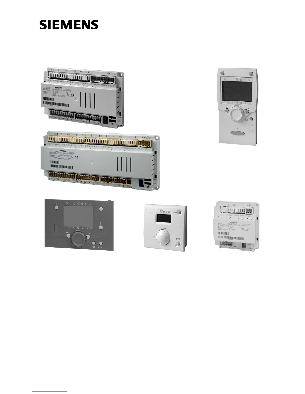
1 Overview
The present User Manual describes the products listed in the following table and covers
handling and configuration of the controls for readers ranging from endusers to heating
engineers.
Product No. (ASN) Name
RVS41.813 Basic unit heat pump
RVS61.843 Basic unit heat pump
AVS75.390 Extension module
AVS37.290 Operator unit without text display (PCB version)
AVS37.294 Operator unit with text display
QAA75.610 Room unit, for wiring
QAA75.611 Room unit, for wiring, with backlit display
QAA78.610 Room unit, wireless
QAA55.110 Room unit
RDX33.21
RDX43.2 Room thermostat with LCD to release heat pump
AVS38.291 Dummy cover (96 x 144 mm)
AVS71.390 RF module
AVS14.390 RF repeater
AVS13.399 Outside sensor with RF module
AVS82.490 Ribbon cable for extension module
AVS82.491 Ribbon cable for operator unit
The following training / demonstration cases are available:
KF8921 Demo case for RVS61.843
KF8920 Demo case for RVS41.813
The following products are described in separate pieces of documentation:
QAC34 Outside sensor
QAD36 Strap-on temperature sensor
QAZ36 Immersion temperature sensor
10/258
Siemens Switzerland Ltd User manual RVS61.843, RVS41.813 CE1U2355en_02
HVAC Products 1 Overview 28. September 2009
Page 11
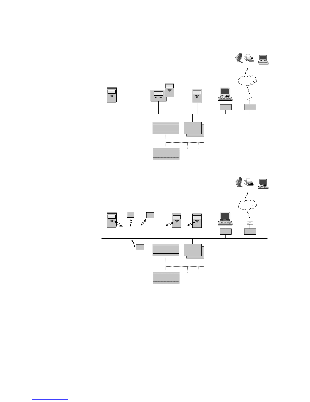
1.1 Product range overview
1.1.1 Topology
Remote
Service Tool
Mobile, SMS, Pager, Fax,
WEB,
Telephone
Network
Telephone
SMS
OCI611
OCI700
ACS700
BSB :
Boiler System Bus
Room
Unit
Service Unit
(RU)
HMI
HMI
(RU)
wired
wired
wired
Basic Unit
RVSxx
Extension
mod. AVS75…
(max. 2)
BSB-W
LPB : Local Process Bus
Basic Unit
RVS...
LPB
Wired
Remote
Service Tool
Mobile, SMS, Pager, Fax,
WEB,
Telephone
Network
Telephone
SMS
OCI611
OCI700
RF
module
ACS700
BSB :
Boiler System Bus
Room
Unit
RF
Repeater
RF
Toutside
BSB-RF
Service Unit
(RU)
HMI
(RU)
wireless
wireless
wireless
Basic Unit
RVSxx
Extension
mod. AVS75…
(max. 2)
BSB-W
LPB : Local Process Bus
Basic Unit
RVS...
LPB
Wireless
11/258
Siemens Switzerland Ltd User manual RVS61.843, RVS41.813 CE1U2355en_02
HVAC Products 1 Overview 28. September 2009
Page 12
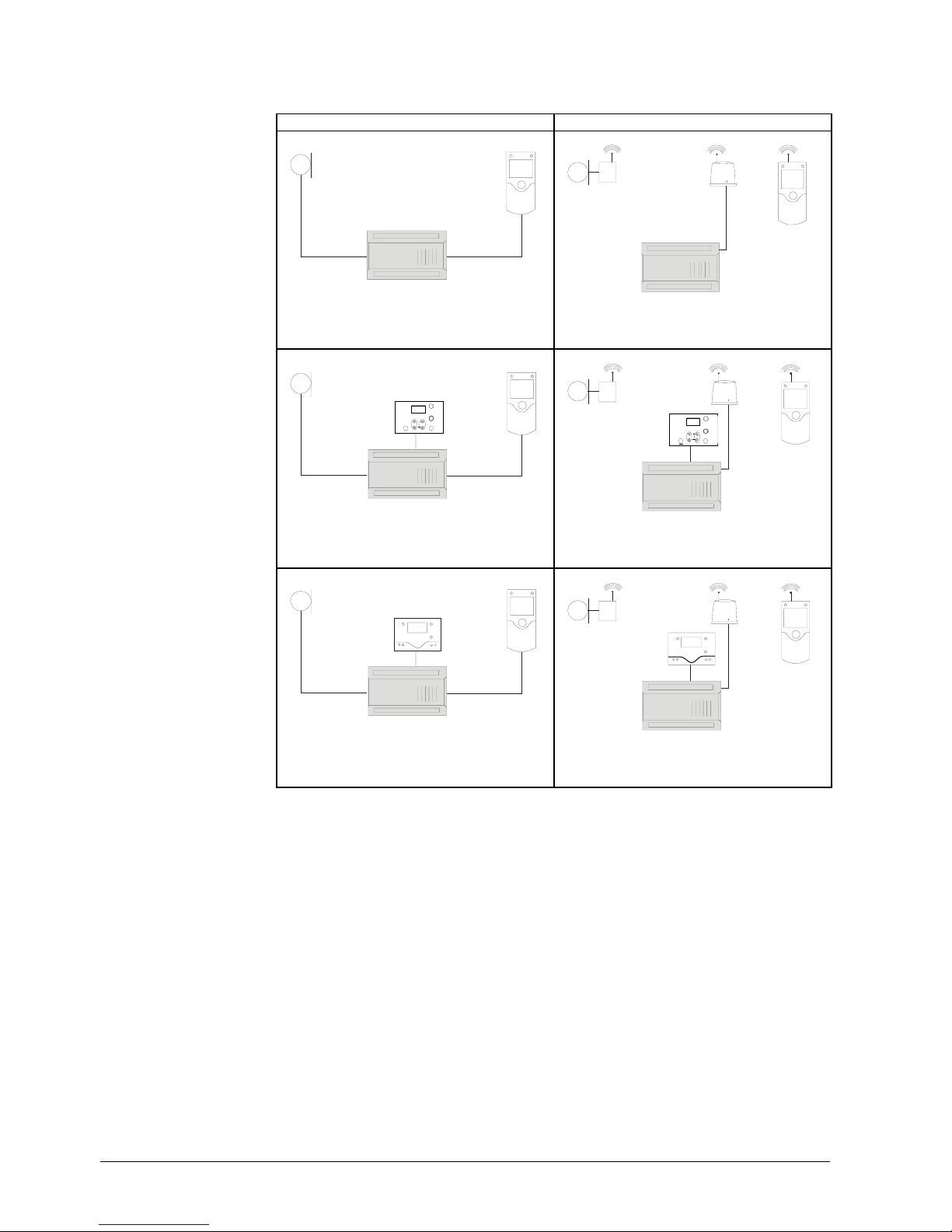
1.1.2 Operation options
Wired Wireless
C
D
A
2359Z01
T
C
D
F
A
2359Z03
T
Operation w
ith room
unit
C
E1
D
A
2359Z66
T
C
D
F
A
2359Z67
T
E1
Operation w
ith operator
unit "basic"
(optionally with additional
room unit)
C
E
D
A
2359Z02
T
C
D
F
A
E
2359Z04
T
Operation w
ith "cleartext"
operator unit
(optionally with additional room
unit)
A Basic unit RVS…
C Room unit QAA75… / 78… / QAA55..
D Outside sensor AVS13…
E Operator unit AVS37.294 (clear text)
E1 Operator unit AVS37.390 (basic)
F RF module AVS71…
12/258
Siemens Switzerland Ltd User manual RVS61.843, RVS41.813 CE1U2355en_02
HVAC Products 1 Overview 28. September 2009
Page 13

2 Safety notes
2.1 Notes on product liability
• The products may only be used in building services plant and on applications as
described in this document
• When using the products, all requirements specified in the chapters on "Handling"
and "Technical data" must be satisfied
• Local regulations (for installation, etc.) must be complied with
• Do not open the units. If not observed, warranty becomes void.
13/258
Siemens Switzerland Ltd User manual RVS61.843, RVS41.813 CE1U2355en_02
HVAC Products 2 Safety notes 28. September 2009
Page 14
14/258
Siemens Switzerland Ltd User manual RVS61.843, RVS41.813 CE1U2355en_02
HVAC Products 3 Mounting and installation 28. September 2009
2359Z09
3 Mounting and installation
3.1 Regulations
• Prior to installing the units, power must be turned off
• The connections for mains and low-voltage are separated
• For wiring, the requirements of safety class II must be satisfied.
• One and the same sensor cannot be connected to several inputs
Sensor and power cables must not be run in the same cable duct
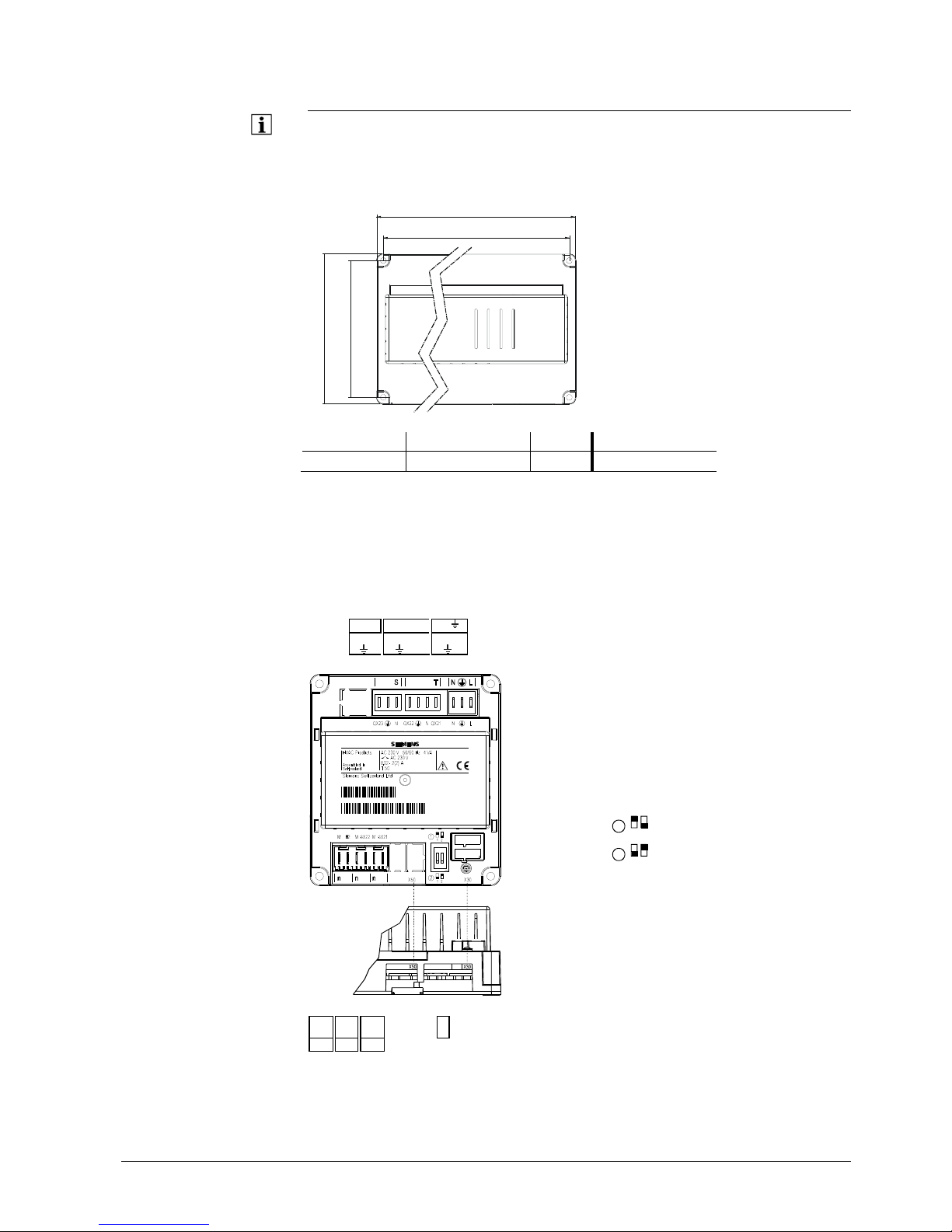
3.2 Heat pump controller RVS..
Engineering
• Air circulation around the controller must be ensured, allowing the unit to emit the
heat produced by it.
A clearance of at least 10 mm must be provided for the unit's cooling slots at the top
and bottom of the housing.
That space should not be accessible and no objects should be placed there. If the
controller is enclosed in another (insulating) casing, a clearance of up to 100 mm
must be observed around the cooling slots
• The controller is designed conforming to the directives for safety class II devices
mounted in compliance with these regulations
• Power to the controller may only be supplied when completely fitted. If this is not
observed, there is a risk of electric shock hazard near the terminals and through the
cooling slots
• The controller must not be exposed to dripping water
• Permissible ambient temperature when mounted and when ready to
operate: 0…50 °C
• Power cables must be clearly separated from low-voltage cables (sensors) observing
a distance of at least 100 mm
• Heat pump
• Control panel
• Housing for wall mounting
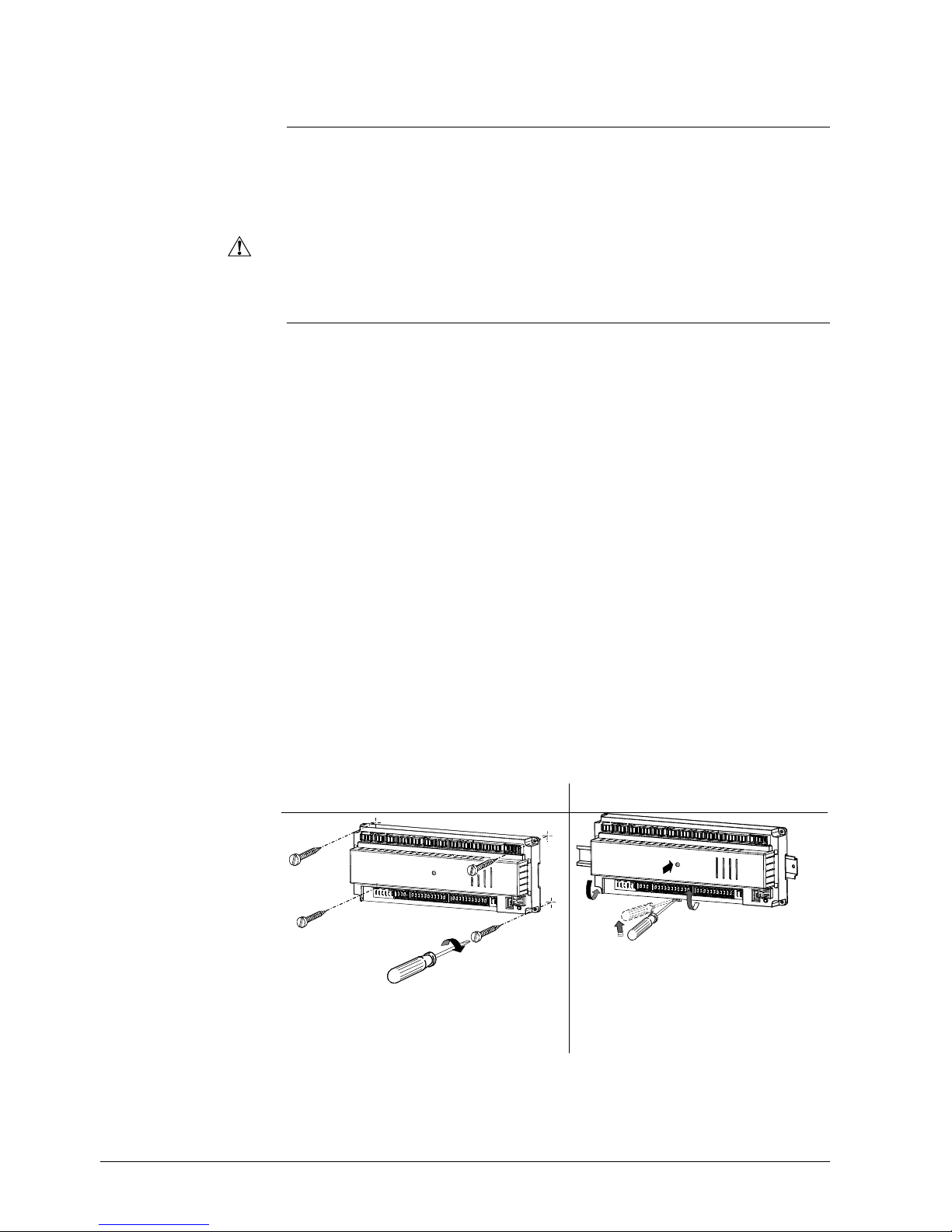
Mounting method
Scre
wed
On DIN rail
A: Mounting / B: Removal
Note:
To mount the controller on a DIN rail, a mounting
clip is required!
Electrical installation
Mounting location
A1
A2
B1
B2
2359Z11
Page 15
15/258
Siemens Switzerland Ltd User manual RVS61.843, RVS41.813 CE1U2355en_02
HVAC Products 3 Mounting and installation 28. September 2009
2359Z10
x
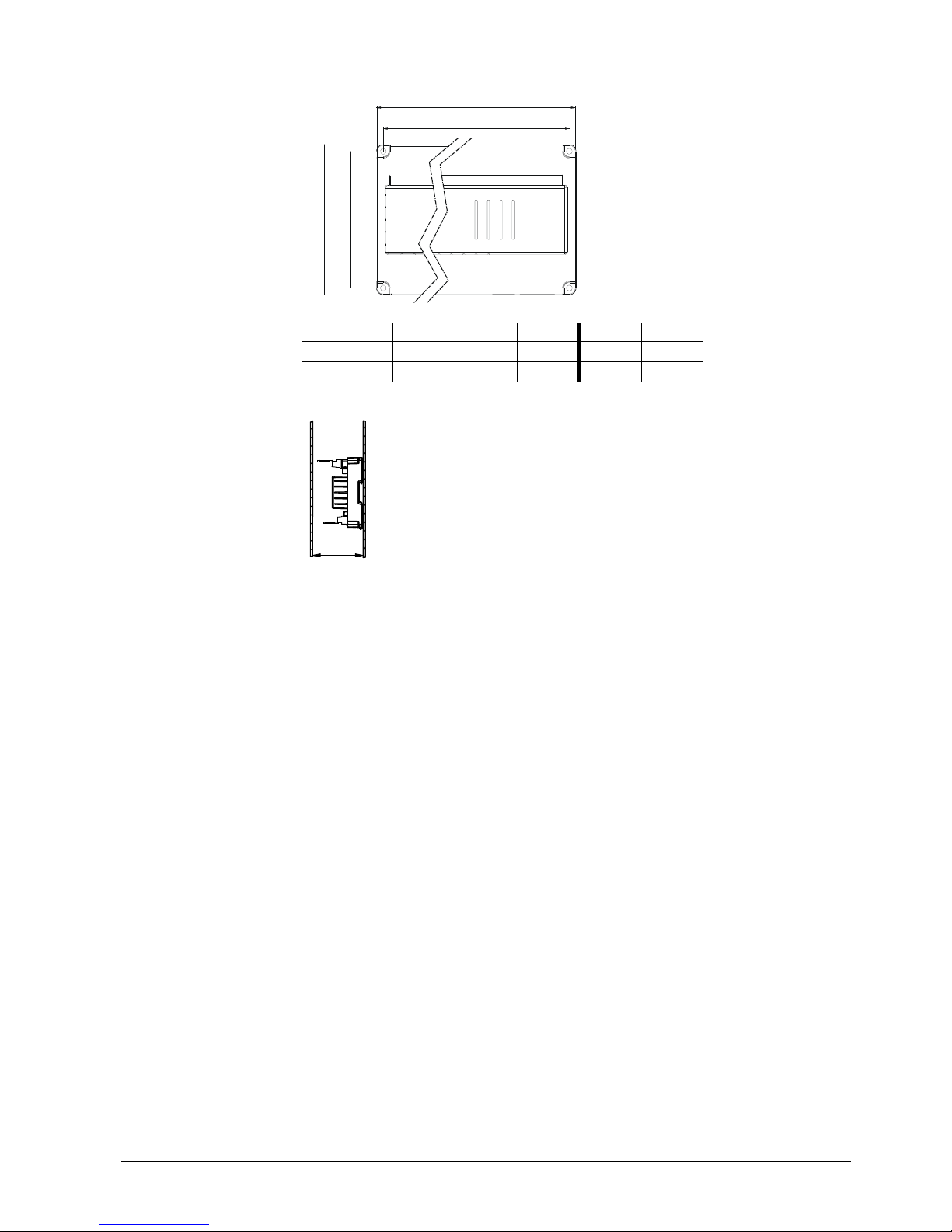
Dimensions and drilling plan
L
BL1B1
2358M01
L B H L1 B1
RVS61.843
281 121 52 270 110
RVS41.813
181 121 52 170 110
Dimension X:
Connectors with tongues, minimum 70 mm
Connector without tongues, minimum 60 mm
Total height required
Dimensions in mm
Page 16
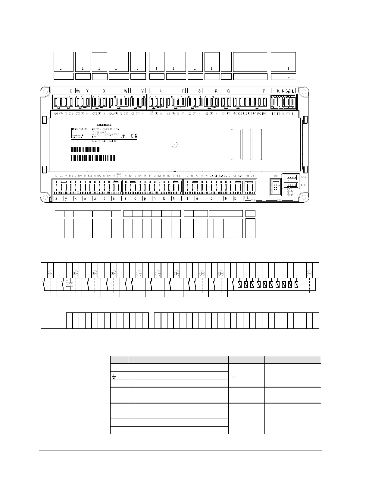
3.2.1 Connection terminals RVS61.843
QX4
N
QX3
N
QX2NQX1
Q9
N
Q8/K19
N
Y2NY1
Q2NQ3NK1
E11
EX6
EX5
EX4
EX3
EX2
EX1
E10E9N
L
N
M
B91MB71MB1MB21MB9MB3
H3MH1G+CL-
CL+
CL-
CL+
CL-
CL+
Y XW
V
UTSRQ P
rqepn
kh
b
K
L
235
5
Z09
QX6NQX5
Z
EX7
M
BX5MBX4MBX3MBX2
M
BX1MB84/B92
yxw
ut s
M
UX
z
MB
DB
a
M
B81
f
070621A
000020RVS61. 843/109
1PRVS61.843/ 109
S070621000020
Connection diagram
QX6
N
QX5
QX4
N
QX3
N
QX2
N
QX1
Q9
N
Q8
N
Y2
NY1Q2
N
Q3NK1
E11
EX7
EX6
EX5
EX4
EX3
EX2
EX1
E10E9N
L
2355Z 02
MUXM
BX 5MBX 4MBX 3MBX 2MBX 1
M
M
B91MB71MB1MB21MB9MB3MB81H3MH1G+
CL-
CL+
CL-
CL+
CL-
CL+MBDB
B84/B92
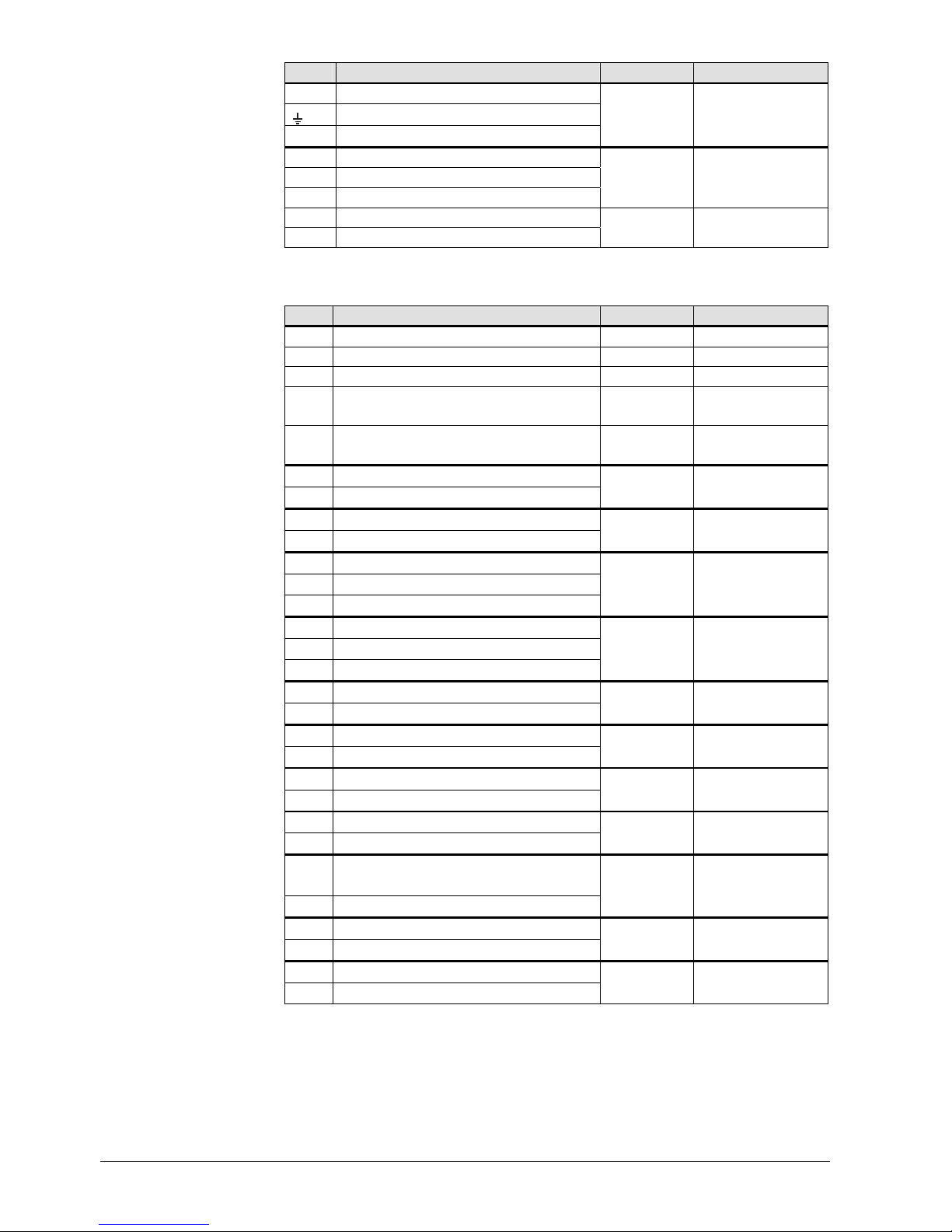
Terminal markings:RVS41.813
Use Terminal Connector type
L Mains connection, live AC 230 V
Mains connection, protective earth
N Mains connection, neutral conductor
L
N
AGP4S.03E/109
E9
Low-pressure
E10
High-pressure
K
AGP4S.02J/109
EX1 Multifunctional input EX1
EX2 Multifunctional input EX2
EX3 Multifunctional input EX3
EX4 Multifunctional input EX4
P
AGP8S.07A/109
Mains voltage
16/258
Siemens Switzerland Ltd User manual RVS61.843, RVS41.813 CE1U2355en_02
HVAC Products 3 Mounting and installation 28. September 2009
Page 17
17/258
Siemens Switzerland Ltd User manual RVS61.843, RVS41.813 CE1U2355en_02
HVAC Products 3 Mounting and installation 28. September 2009
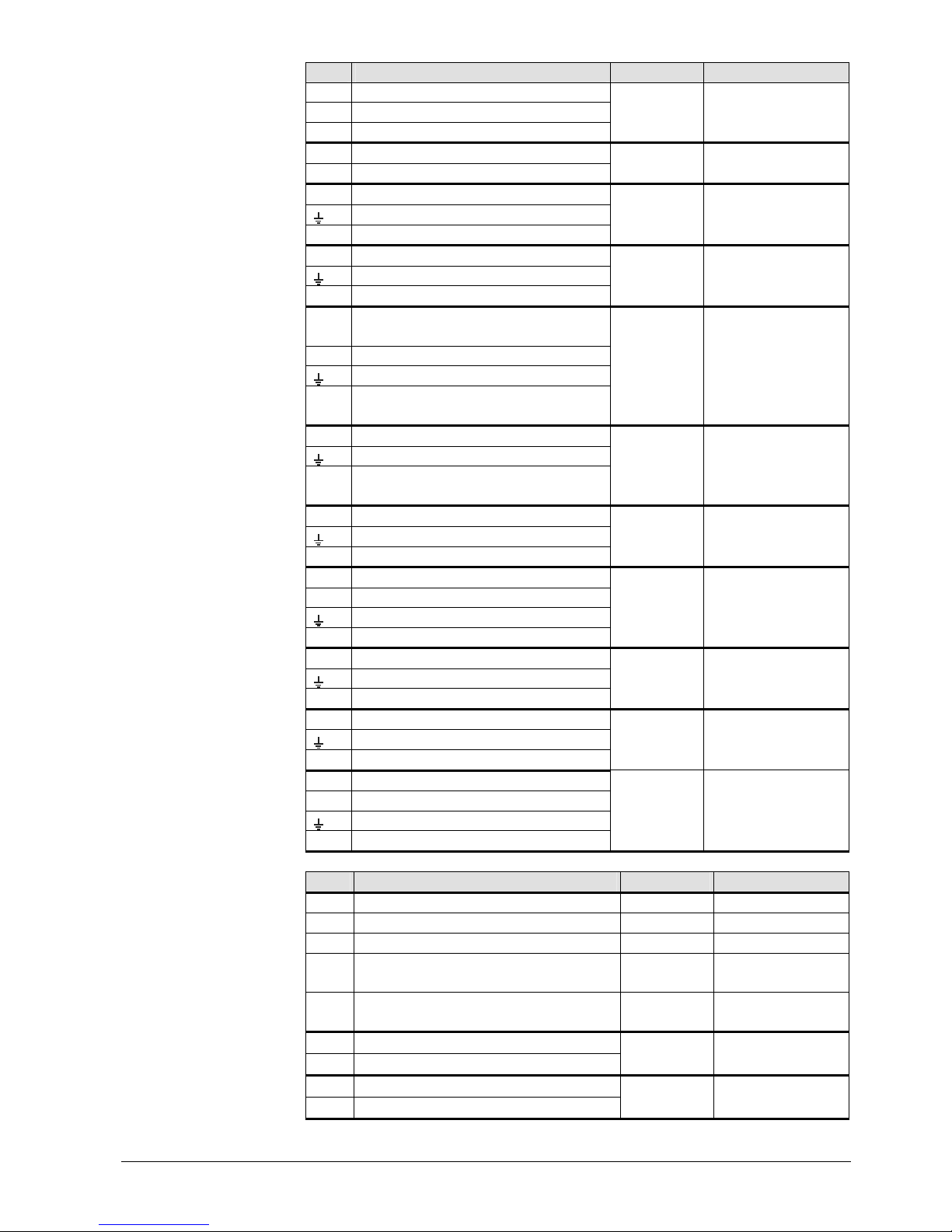
Use Terminal Connector type
EX5 Multifunctional input EX5
EX6 Multifunctional input EX6
EX7 Multifunctional input EX7
E11
Compressor 1 overload E11
K1
Compressor stage 1
Q
AGP8S.02E/109
N Neutral conductor
Protective earth
Q3 DHW charging pump / diverting valve
R
AGP8S.03A/109
N Neutral conductor
Protective earth
Q2 1. 1st heating circuit pump
S
AGP8S.03B/109
Y1 1. 1st heating circuit mixing valve
opening
N Neutral conductor
Protective earth
Y2 1. 1st heating circuit mixing valve
closing
T
AGP8S.04B/109
N Neutral conductor
Protective earth
Q8
K19
Source pump
Fan
U
AGP8S.03C/109
N Neutral conductor
Protective earth
Q9 Condenser pump
V
AGP8S.03D/109
QX1 1. Multifunctional output
N Neutral conductor
Protective earth
QX2 2. Multifunctional output
W
AGP8S.04E/109
N Neutral conductor
Protective earth
QX3 3. Multifunctional output
X
AGP8S.03E/109
N Neutral conductor
Protective earth
QX4 4. Multifunctional output
Y
AGP8S.03G/109
QX5 5. Multifunctional output
N Neutral conductor
Protective earth
QX6 6. Multifunctional output
Z
AGP8S.04C/109
Use Terminal Connector type
Service tool LPB LPB Service tool BSB BSB RF module AVS71.390 X60 Extension module AVS75.390 X50
AVS82.490/109
(cable)
Operator unit (HMI) X30
AVS82.491/109
(cable)
DB
LPB data bus
MB
LPB ground bus
a
AGP4S.02H/109
CL+ BSB data bus
CL- BSB ground bus
b
AGP4S.02A/109
Low-voltage
Page 18

18/258
Siemens Switzerland Ltd User manual RVS61.843, RVS41.813 CE1U2355en_02
HVAC Products 3 Mounting and installation 28. September 2009
Use Terminal Connector type
CL+ Data bus room unit 2
CL- Ground bus room unit 2
b
AGP4S.02 A /109
CL+ Data bus room unit 1
CL- Ground bus room unit 1
G+ Power supply optional lighting
b
AGP4S.03D/109
H1 Digital / DC 0...10 V input H1
M Ground
H3 Digital / DC 0...10 V input H3
e
AGP4S.03G/109
B81 Hot-gas temperature sensor 1
M Ground
f
AGP4S.02B/109
B3 DHW temperature sensor
M Ground
h
AGP4S.02C/109
B9 Outside sensor
M Ground
k
AGP4S.02D/109
B21
Flow temperature sensor heat pump
M
Ground
n
AGP4S.02F/109
B1 Flow temperature sensor HC1
M Ground
p
AGP4S.02G/109
B71 Return temperature sensor heat pump
M Ground
q
AGP4S.02K/109
B91
Source inlet temperature
M Ground
r
AGP4S.02L/109
B84
B92
Evaporator temperature sensor
Source outlet temperature sensor
M Ground
s
AGP4S.02S/109
BX1
Multifunctional sensor input BX1
M Ground
t
AGP4S.02M/109
BX2
Multifunctional sensor input BX2
M Ground
u
AGP4S.02N/109
BX3
Multifunctional sensor input BX3
M Ground
w
AGP4S.02P/109
BX4
Multifunctional sensor input BX4
M Ground
x
AGP4S.02R/109
BX5
Multifunctional sensor input BX5
M Ground
Y
AGP4S.02T/109
UX
Multifunctional analog output UX
M Ground
z
AGP4S.02U/109
Page 19

3.2.2 Connection terminals of RVS41.813
U R
BQ
X S LNE
071029A
000020RVS41.81 3/109
235 5Z01
B
X
S R
QX8LQX7
QX6
QX5
QX4
QX3NN
QX2NQX1NEX7
EX6
EX5
EX4
EX3
EX2
EX1
N
L
2355Z03
B91
M
BX5MBX4
M
MB9M
M
UX1H3MH1G+
CL-
CL+
CL-
CL+MBDB
B84/B92
Connection diagram
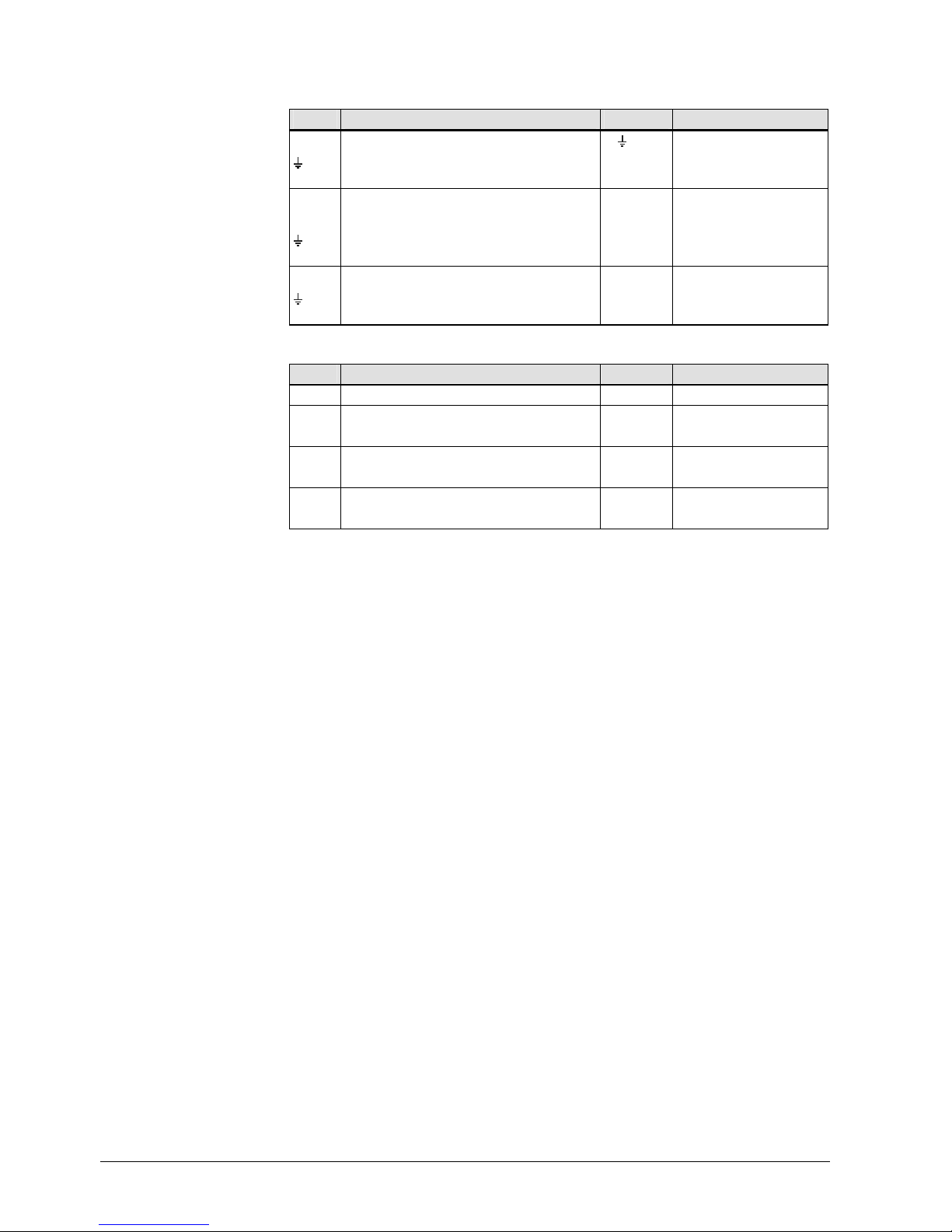
Terminal markings RVS41.813
Use Terminal Connector type
L Mains connection, live AC 230 V
Mains connection, protective earth
N Mains connection, neutral conductor
L
N
AGP4S.03E/109
EX1
Multifunctional input EX1
EX2
Multifunctional input EX2
EX3
Multifunctional input EX3
EX4
Multifunctional input EX4
EX5
Multifunctional input EX5
EX6
Multifunctional input EX6
EX7
Multifunctional input EX7
E AGP4S.07A/109
N
Neutral conductor
Protective earth
QX1
Multifunctional output
R
AGP8S.03A/109
N
Neutral conductor
Protective earth
QX2
Multifunctional output
U
AGP8S.03C/109
N
Neutral conductor
Protective earth
QX3
Multifunctional output
S
AGP8S.03B/109
Mains voltage
19/258
Siemens Switzerland Ltd User manual RVS61.843, RVS41.813 CE1U2355en_02
HVAC Products 3 Mounting and installation 28. September 2009
Page 20
20/258
Siemens Switzerland Ltd User manual RVS61.843, RVS41.813 CE1U2355en_02
HVAC Products 3 Mounting and installation 28. September 2009
Use Terminal Connector type
N
Neutral conductor
Protective earth
QX4
Multifunctional output
X
AGP8S.03E/109
QX5
Multifunctional output
QX6
Multifunctional output
QX7
Multifunctional output
B AGP8S.03H/109
L
Potentialfree contact 230 V
QX8
Multifunctional output
Q
AGP8S.02E/109
Use Terminal Connector type
Service tool LPB LPB Service tool BSB BSB RF module AVS71.390 X60 Extension module AVS75.390 X50
AVS82.490/109
(cable)
Operator unit (HMI) X30
AVS82.491/109
(cable)
DB
LPB data bus
MB
LPB ground bus
a AGP4S.02H/109
CL+ BSB data bus
CL- BSB ground bus
b AGP4S.02A/109
CL+ Data bus room unit 1
CL- Ground bus room unit 1
G+ Power supply optional lighting
b AGP4S.03D/109
H1 Digital / DC 0...10 V input H1
M Ground
H3 Digital / DC 0...10 V input H3
e AGP4S.03G/109
UX
Multifunctional analog output
M Ground
z AGP4S.02U/109
BX1
Multifunctional sensor input
M Ground
h AGP4S.02C/109
B9 Outside sensor
M Ground
k AGP4S.02D/109
B91
Source inlet temperature
M Ground
r AGP4S.02L/109
B84/92
Evaporator temperature sensor
Source outlet temperature sensor
M Ground
s AGP4S.02S/109
BX4
Multifunctional sensor input
M Ground
n AGP4S.02F/109
BX5
Multifunctional sensor input
M Ground
q AGP4S.02K/109
Low-voltage
Page 21
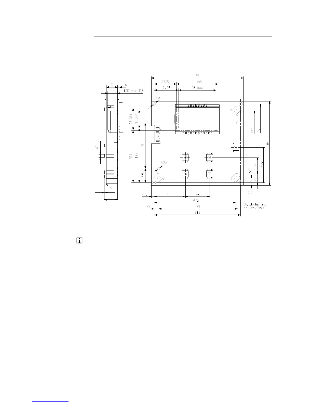
3.3 Extension module AVS75.390
For planning, mounting location and mounting method, refer to the information given for
the basic mod
ules.
Dimensions and drilling plan
L
BL1B1
2358M01
Dimensions in mm
L
B H L1 B1
AVS75.390
109 121 52 98 110
The AVS75.390 extension module must be connected to terminal
X50 of the basic unit
using the AVS83.490/109 connecting cable. The connectors are coded.
Connections
3.3.1 Connection terminals AVS75.390
S T N L
- - -
QX2
3
N
QX2
2
N
QX21
N L
050110A
000020
AVS75.390/109
1PAVS75.390/109
S050110000020
2359Z49
1
12
= module 2
2
1
2
= module 1
M
H2 M BX22 M BX21 - - - -
X30
n n n
21/258
Siemens Switzerland Ltd User manual RVS61.843, RVS41.813 CE1U2355en_02
HVAC Products 3 Mounting and installation 28. September 2009
Page 22
Terminal markings
Use Space Connector type
L Live AC 230 V basic unit N L AGP4S.03E/109
Protective earth
N Neutral conductor
QX21 Assignment according to function T AGP8S.04B/109
N Neutral conductor
Protective earth
QX22 Assignment according to function
N Neutral conductor S AGP8S.03B/109
Protective earth
QX23 Assignment according to function
Mains voltage
Use Space Connector type
Operator unit X30
AVS82.491/109
BX21 Assignment according to function AGP4S.02F/109
M Ground n
BX22 Assignment according to function AGP4S.02F/109
M Ground n
H2 Digital / 0...10 V input AGP4S.02F/109
M Ground n
Low
-voltage
Assignment of terminals
The 2 parameters
•
Function extension module 1 (operating line 6020)
• Function extension module 2 (6021)
are used to define usage of the respective module.
22/258
Siemens Switzerland Ltd User manual RVS61.843, RVS41.813 CE1U2355en_02
HVAC Products 3 Mounting and installation 28. September 2009
Page 23
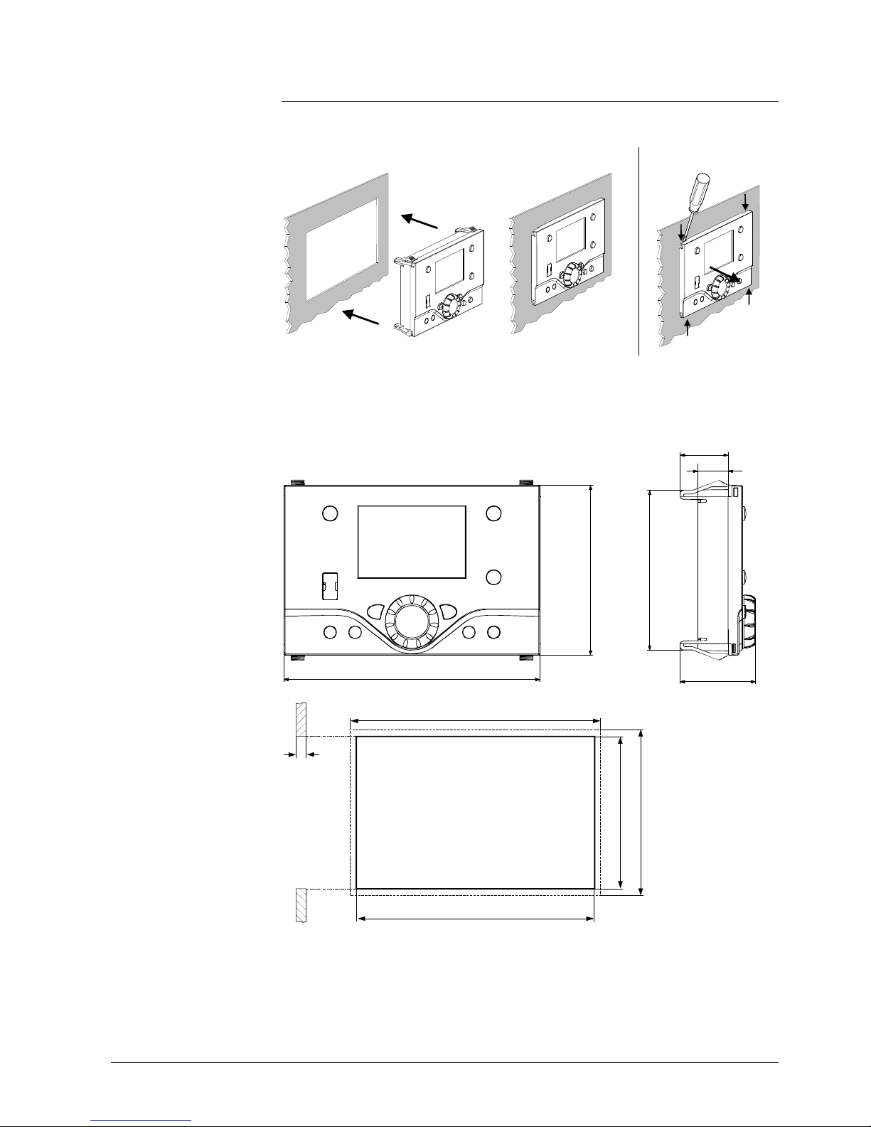
3.4 Operator unit AVS37.294
Mounting method
Mounting
Removal
2358Z30
2358Z31
2358Z32
Connections
The AVS37.2
94 operator unit must be connected to terminal X30 of the basic unit using
the AVS82.491/109 connecting cable.
The connectors are coded.
2358M03
144
96
90
27
42.4
17
Dim
ensions
(144)
0.5...3.0
92
+0.8
0
138
+1
0
2358M05
(96)
Panel cutout
23/258
Siemens Switzerland Ltd User manual RVS61.843, RVS41.813 CE1U2355en_02
HVAC Products 3 Mounting and installation 28. September 2009
Page 24
3.5 Operator unit AVS37.390
Connections
The AVS37.390 operator unit must be connected to terminal X30 of the basic unit using
the AVS82.491/109 connecting cable. The connectors are coded.
Dimensions
235 4M 01
13
0,5
A
A Control panel, front
The AVS37.3
90 operator unit is a PCB version without casing, supplied by Siemens.
24/258
Siemens Switzerland Ltd User manual RVS61.843, RVS41.813 CE1U2355en_02
HVAC Products 3 Mounting and installation 28. September 2009
Page 25
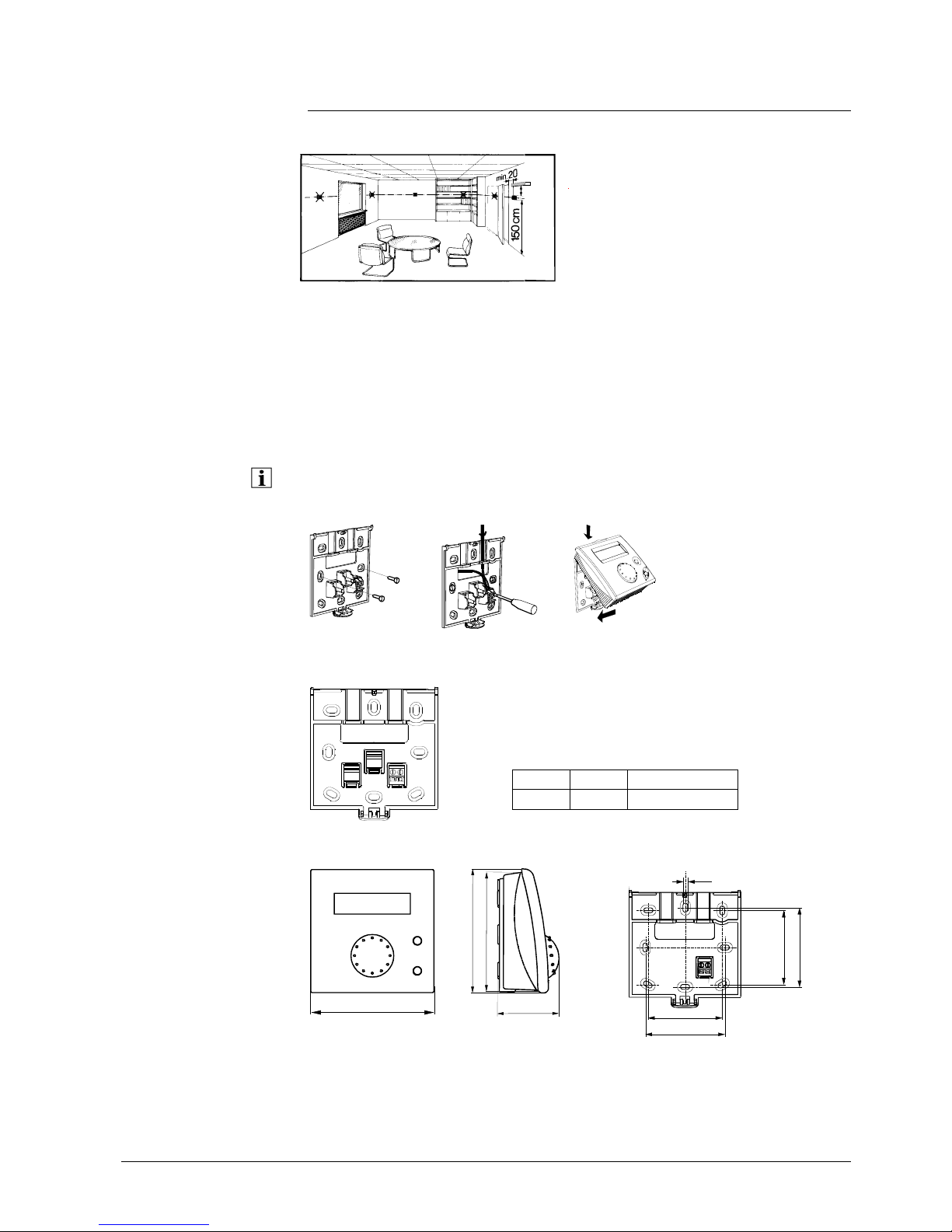
3.6 Room unit QAA55…
Engineering
min.
10 cm
2261Z03
The room unit should be located in the main living room while giving consideration to
the following criteria:
• The place of installation should be chosen so that the sensor can capture the room
temperature as accurately as possible without getting adversely affected by direct
solar radiation or other heat or refrigeration sources (about 1.5 meters above the
floor)
• In the case of wall mounting, there must be sufficient clearance above the unit,
enabling it to be fitted and removed
When the unit
is removed from its base, power is cut off so that the unit is out of
operation.
2284Z33a
2284Z34a
2284Z35a
Mounti
ng
•
The controller must not be exposed to dripping water
1
34
562
2284Z40
Connections
1 CL+ BSB data
2 CL- BSB ground
Dimensions and drilling plan
2284M02
96
9
6
9
1
4
7
12
2359Z27
4,2
56
60
56
60
25/258
Siemens Switzerland Ltd User manual RVS61.843, RVS41.813 CE1U2355en_02
HVAC Products 3 Mounting and installation 28. September 2009
Page 26
3.7 Room unit QAA75…
Engineering
min.
10 cm
2261Z03
The room unit should be located in the main living room while giving consideration to
the following criteria:
• The place of installation should be chosen so that the sensor can capture the room
temperature as accurately as possible without getting adversely affected by direct
solar radiation or other heat or refrigeration sources (about 1.5 meters above the
floor)
• In the case of wall mounting, there must be sufficient clearance above the unit,
enabling it to be fitted and removed
When the unit
is removed from its base, power is cut off so that the unit is out of
operation.
Mounti
ng method
2359Z21
2359Z25
2359Z20
2359Z26
2359Z24
Connections
Terminal Designation
QAA75.610 QAA75.611
1 CL+ BSB data BSB data
2 CL- BSB ground BSB ground
3 G+ Reserved Power supply DC 12 V
26/258
Siemens Switzerland Ltd User manual RVS61.843, RVS41.813 CE1U2355en_02
HVAC Products 3 Mounting and installation 28. September 2009
Page 27
Dimensions and drilling plan
42
185
2359Z12
100
82
2359Z50
4,2
9
56
60
100
80
11
39
67
27/258
Siemens Switzerland Ltd User manual RVS61.843, RVS41.813 CE1U2355en_02
HVAC Products 3 Mounting and installation 28. September 2009
Page 28
3.8 RF components
The wireless components should be located such that transmission is as interferencefree as possible. The following criteria must be observed:
• Not in the vicinity of electrical cables, strong magnetic fields or equipment, such as
PCs, TV sets, microwave ovens, etc.
• Not near larger metal structures or constructional elements with fine metal meshes,
such as special glass or special concrete
• The distance to the transmitter should not exceed 30 meters or 2 floors
3.8.1 RF module AVS71.390
The RF module extends the product range by introducing wireless communication. With
this type of device, the system components, such as room units, transmit data with no
need for laying cables.
E
ngineering Do not install t
he RF module inside metal casings (e.g. inside the heat pump).
2359Z23
Mounti
ng method
2359Z57
A
B
LED
Button
Connection The prefabricated cable is to
be connected to terminal X60 of the controller.
Prior to conne
cting the module, the basic unit must be disconnected from power!
Radio conne
ction Establishment
of the wireless connection is described in the following sections which
cover the relevant RF components.
43
2354Z11
Dimensions and drilling
plan
28/258
Siemens Switzerland Ltd User manual RVS61.843, RVS41.813 CE1U2355en_02
HVAC Products 3 Mounting and installation 28. September 2009
Page 29
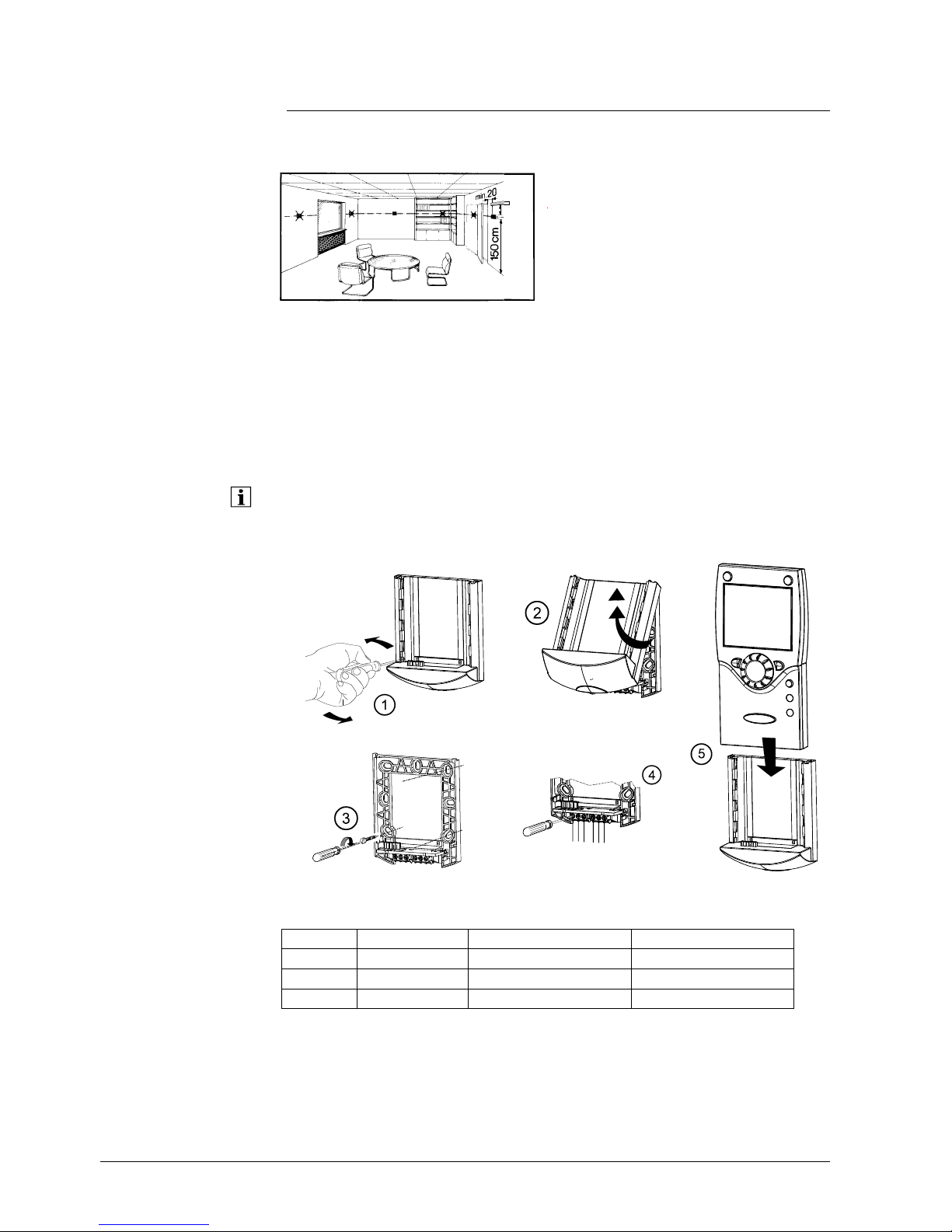
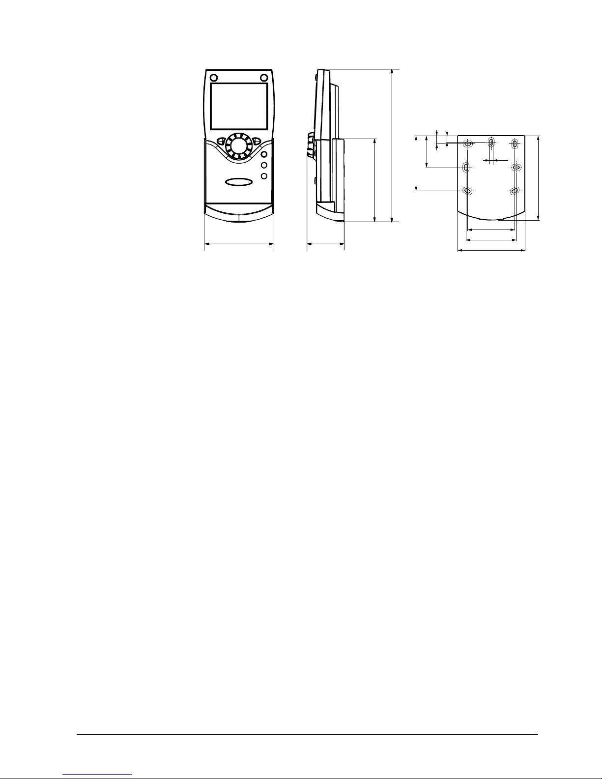
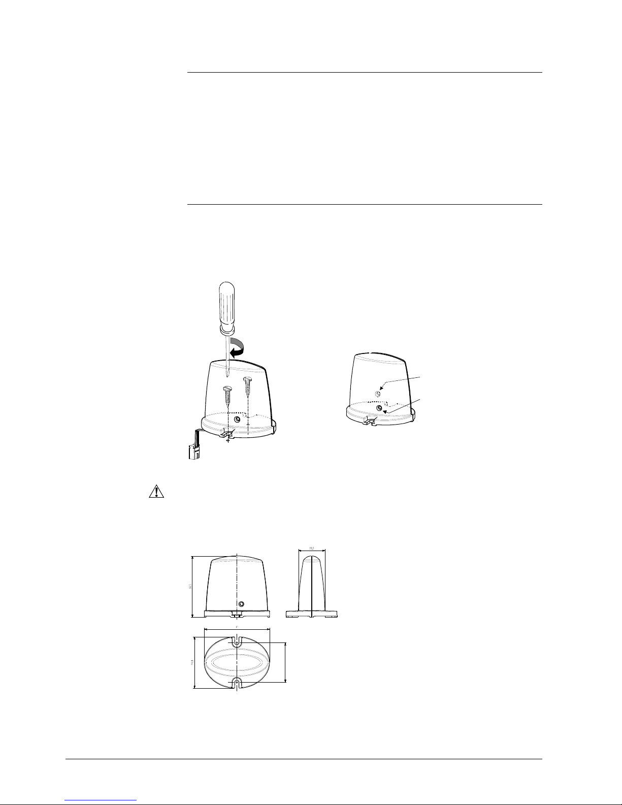
3.8.2 Room unit QAA78.610
Engineering
min.
10 cm
2261Z03
The room unit should be located in the main living room while giving consideration to
the following criteria:
• The place of installation should be chosen so that the sensor can capture the room
temperature as accurately as possible without getting adversely affected by direct
solar radiation or other heat or refrigeration sources (about 1.5 meters above the
floor)
• In the case of wall mounting, there must be sufficient clearance above the unit,
enabling it to be fitted and removed
Mounting with the
base
2359Z26
2359Z25
2359Z20
2359Z21
2359Z22
29/258
Siemens Switzerland Ltd User manual RVS61.843, RVS41.813 CE1U2355en_02
HVAC Products 3 Mounting and installation 28. September 2009
Page 30
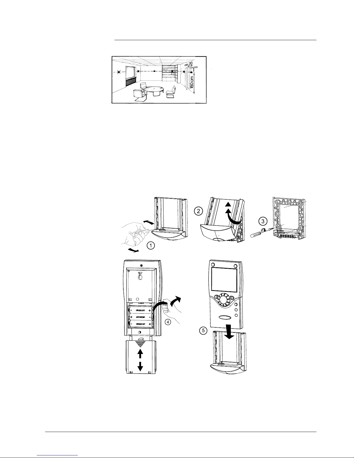
Mounting without the
base
2359Z61
Connections / power supply
The room unit is po
wered by three 1.5 V Alkali batteries type AA (LR06).
Radio connection
Make the radio connection in the vicinity o
f the RF module prior to mounting so that all
system components are within easy reach.
Prerequisite for the radio connection is that all components receive power, which
means that the RF module must be correctly connected to the controller and the
batteries must be correctly installed in the room unit.
Establishment
1.
Press the button on the installed RF module for at least 8 seconds until the LED
on the module starts blinking at high frequency.
2. Press the OK button on the room unit to switch to programming.
3. Press the info button for at least 3 seconds and select operating level
"Commissioning" with the setting knob. Then, press the OK button.
4. Select menu "Wireless" and press the OK button.
5. Select operating line "Used as" (40) and make the appropriate selection. Then,
press the OK button.
6. Set the setting knob to "YES" and press the OK button. The process of opening
the connection is started.
7. The display shows the progress of opening the connection in %. This process
can take 2 to 120 seconds.
8. The connection is established when "Device ready" appears and the LED on the
RF module extinguishes
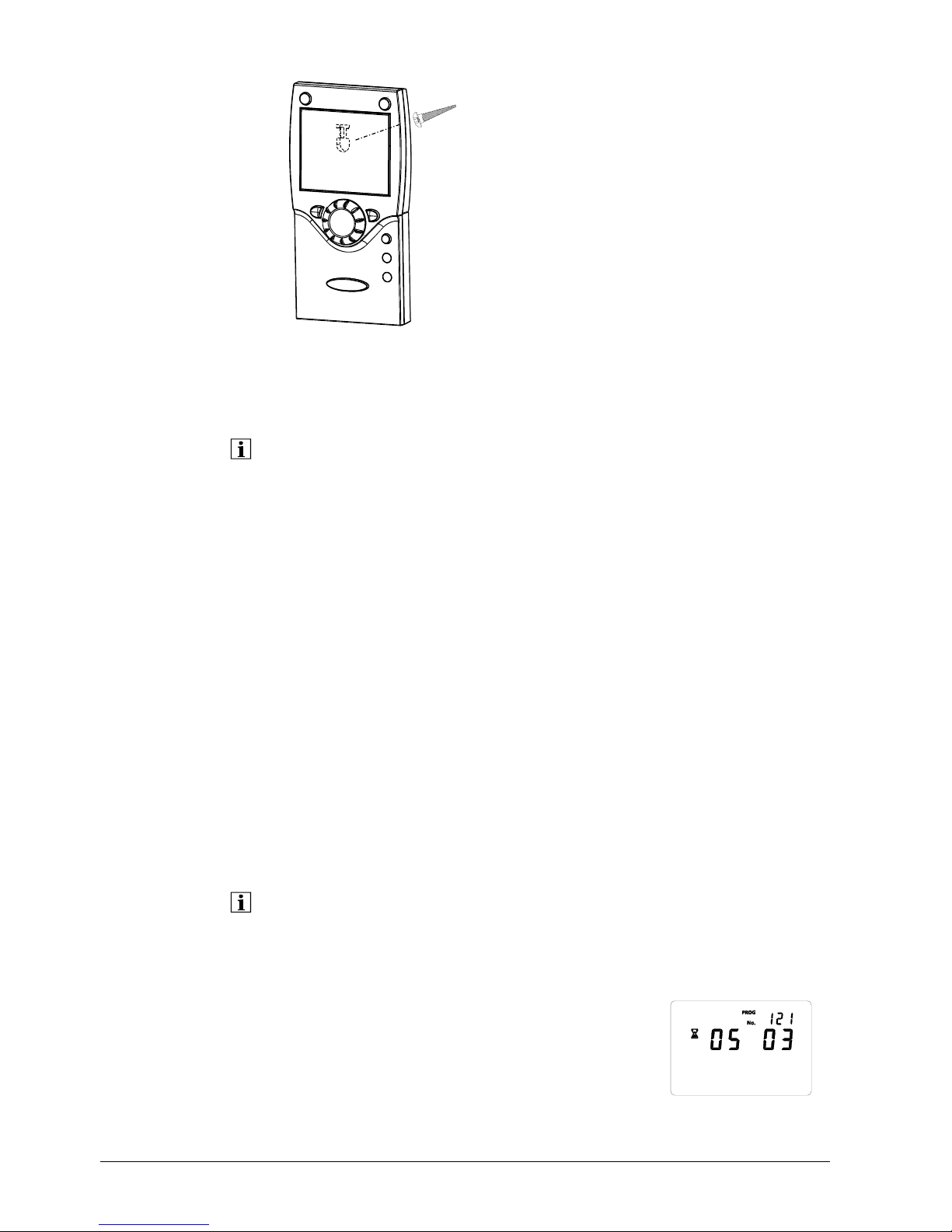
The test is made to check the quality of the radio link. Testing
• The test can be aborted by pressing the ESC button.
• While the radio link can be opened on the controller, the test should be made at the
location where the room unit will be installed
On the room unit, as described above (points 2 through 4), select menu "Radio" and
activate the test mode on setting line "Test mode" (121).
Example of a display during the test:
The digits on the left show telegrams that have
been sent, the digits on the right telegrams that
have been received. The test will be ended
after 24 telegrams. The test is considered
2359Z140
Oper ator s ect ion
Testmode
30/258
Siemens Switzerland Ltd User manual RVS61.843, RVS41.813 CE1U2355en_02
HVAC Products 3 Mounting and installation 28. September 2009
Page 31

successful when at least 50% of the telegrams
sent have been received.
If the test was not successful, some other mounting location should be chosen, or the
AVS14.390 RF repeater should be used.
Dimensions and drilling plan
42
185
2359Z12
100
82
2359Z50
4,2
9
56
60
100
80
11
39
67
31/258
Siemens Switzerland Ltd User manual RVS61.843, RVS41.813 CE1U2355en_02
HVAC Products 3 Mounting and installation 28. September 2009
Page 32

32/258
Siemens Switzerland Ltd User manual RVS61.843, RVS41.813 CE1U2355en_02
HVAC Products 3 Mounting and installation 28. September 2009
2359Z53
3.8.3 Wireless outside sensor AVS13.399
• The radio transmitter must be installed inside the building.
• The radio transmitter’s mounting location should be chosen such that batteries
can be easily changed
Mounting method
RF transmitter Outside sensor
The outside sensor is to be connected to the radio transmitter via a 2-core cable, the
connections are interchangeable.
The device is powered by two 1.5 V alkaline batteries type AAA (LR03).
Connections
2359Z54
2359Z30
2359Z33
2359Z59
2359Z31
2359Z55
AAA
AAA
Removing the
battery transit tab
Battery
2359Z32
Page 33

33/258
Siemens Switzerland Ltd User manual RVS61.843, RVS41.813 CE1U2355en_02
HVAC Products 3 Mounting and installation 28. September 2009
Radio connection
Make the radio connection in the vicinity of the RF module prior to mounting so that all
system components are within easy reach.
Prerequisite for the radio link is that all components receive power, which means that
the RF module must be correctly connected to the basic unit and the batteries must be
correctly installed in the room unit.
1. Press the button on the RF module for at least 8
seconds until the LED on the radio module
starts blinking at high frequency.
2. Press the button on the transmitter of the
wireless outside sensor for at least 8 seconds
until that LED also starts blinking at high
frequency.
3. The connection is established when the LED on the RF module extinguishes.
4. Press the button on the transmitter of the wireless outside sensor briefly again
until the LED extinguishes.
The test is made to check the quality of the radio link.
• The test can be aborted by pressing the ESC button.
• While the radio link can be opened on the controller, the test should be made at the
location where the room unit will be installed
1. Press button 3 on the transmitter of the wireless outside sensor for a maximum
of 8 seconds until the LED starts blinking at low frequency.
2. When radio communication works correctly, the LED on the RF module flashes
briefly at 10-second intervals.
3. After the test, press the button on the transmitter of the wireless outside sensor
again briefly until the LED extinguishes.
Dimensions and drilling plan
90
100
32
2359Z16
79,8
91,6
49,7
1811M01
12
2359Z27
4,2
56
60
56
60
3
5,5
Ø 14,1
2524,5
49,5
4
5,5
6
1811M02
Establishment
Testing
2359Z58
AAA
AAA
LED
Button
Page 34

3.8.4 RF repeater AVS14.390
•
To establish the radio connection, the device must be provisionally connected to
power prior to mounting, enabling the radio connection to be opened and tested.
• The RF repeater must be fitted inside the building
Mounting method
1
2359Z30
2
2359Z33
4
2359Z31
Connections
Po
wer is supplied via the enclosed power pack. The wires are interchangeable.
Radio connection
Make the radio connection in the vicinity o
f the RF module prior to mounting so that all
system components are within easy reach.
Prerequisite for the radio link is that all components receive power, which means that
the RF module must be correctly connected to the basic unit and power must be
correctly supplied to the RF repeater.
1. Press the button on the RF module for at least 8
seconds until the LED on the radio module starts
blinking at high frequency.
Establishment
2359Z56
Button
LED
2.
Press the button on the installed radio repeater
until the LED start flashing at high frequency.
3. The connection is established when the LED on
the RF module extinguishes.
The test is made to check the quality of the radio link. Testing
•
The test can be aborted by pressing the ESC button.
• While the radio link can be opened on the controller, the test should be made at the
location where the room unit will be installed
1. Press button 3 on the RF repeater for a maximum of 8 seconds until the LED
starts blinking at low frequency.
2. When radio communication works correctly, the LED on the RF module flashes
briefly at 10-second intervals.
3. After the test, press the button on the RF repeater again briefly until the LED
extinguishes.
Dimensions and drilling plan
90
100
32
2359Z16
12
2359Z27
4,2
56
60
56
60
34/258
Siemens Switzerland Ltd User manual RVS61.843, RVS41.813 CE1U2355en_02
HVAC Products 3 Mounting and installation 28. September 2009
Page 35

3.8.5 Checking the RF components
To check whether the connections to the required system components are operational,
consult menus 130 through 135 on menu "Wireless" (operating level "Commissioning").
35/258
Siemens Switzerland Ltd User manual RVS61.843, RVS41.813 CE1U2355en_02
HVAC Products 3 Mounting and installation 28. September 2009
Page 36

4 Commissioning
Pre
requisites To commission the units, the following working steps must be carried out:
•
Prerequisite is the correct mounting and correct electrical installation and, in the case
of wireless products, correctly working radio connections to all required auxiliary units
• Make all plant-specific settings. Special attention must be paid to menu
"Configuration". For that purpose, the relevant operating level is to be selected as
follows:
Press the OK button on the room unit to switch to programming.
Press the info button for at least 3 seconds and select operating level
"Commissioning" with the setting knob. Then, press the OK button.
• Make the function check as described below
• Reset the attenuated outside temperature
(menu "Diagnostics of consumers", operating line "Outside temp attenuated" (8703))
Functio
n check
To facilitate commissioning and fault tracing, the controller can be used to make input
and output tests. With these tests, the controller’s inputs and outputs can be checked.
To make the tests, switch to menu "Input / output test" and go through all available
setting lines.
If faults occurred during the tests, please refer to the descriptions "Diagnostics of heat
and refrigeration sources" and "Diagnostics of consumers" in this User Manual.
Operating state The current operating state can be checked on menu "State".
Diagnosis For detailed diagnostics of the plant, check menus "Diagnostics heat generation" and
"Diagnostics consumers".
4.1 Heat pump controller
Checking the
LEDs
LED off: No power supply
LED on Ready
LED blinks Local fault
2359Z33
LED
36/258
Siemens Switzerland Ltd User manual RVS61.843, RVS41.813 CE1U2355en_02
HVAC Products 4 Commissioning 28. September 2009
Page 37

5 Handling
5.1 QAA75.. / QAA78… / AVS37..
5.1.1 Operation
Operating elements
Room units
QAA75... /
QAA78…
Selecting pace heating
Selection of DHW heating mode
Quittin
g
the setting
A
doption of setting
A
djustment of Comfort setpoint
Navigation and settings
Occupancy button
Cooling button
Displaying information
Selection of DHW heating
Selection of space
Operator unit
A
VS37..
Information display
A
dopting the setting
Quitting the setting
Service socket (BSB)
Cooling button
HP reset and
defrost button
A
djustment of Comfort setpoint
Navi
g
ation and settings
37/258
Siemens Switzerland Ltd User manual RVS61.843, RVS41.813 CE1U2355en_02
HVAC Products 5 Handling 28. September 2009
Page 38

Display choices
Heating to the Comfort setpoint
Holiday function active
Heating to Reduced setpoint
Reference to heating circuit
Heating to the frost protection setpoint
Service / special functions
Cooling
Error messages
Process running – please wait
Info level activated
Change battery
Programming activated
Heating temporarily switched
off
ECO function active
Display of all segments.
Display
2358Z07
Xxxxxxxxxxxxxxxxxxxxxxxxxxx
Xxxxxxxxxxxxxxxxxxxxxxxxxxx
Xxxxxxxxxxxxxxxxxxxxxxxxxxx
Selecting pace heating mode
This button is
used to switch between the different
operating modes. The selection made is indicated by a
bar which appears below the respective symbol.
Automatic mode
In automatic mode, the room temperature is controlled in accordance with the time
program.
Characteristics of automatic mode:
− Heating mode according to the time program
− Temperature setpoints per heating program "Comfort setpoint" or "Reduced
setpoint"
− Protective functions active
− Automatic summer / winter changeover and automatic 24-hour heating limit active
(ECO functions)
Continuous operation
or
Continuous operation maintains the room temperature at the selected operating level.
Heating to the Comfort setpoint
Heating to Reduced setpoint
Characteristics of continuous operation:
• Heating with no time program
• Protective functions active
• Automatic summer / winter changeover (ECO functions) and automatic 24-hour
heating limit inactive in the case of continuous operation with Comfort setpoint
38/258
Siemens Switzerland Ltd User manual RVS61.843, RVS41.813 CE1U2355en_02
HVAC Products 5 Handling 28. September 2009
Page 39

Protection
When using Protection, the heating system is off. But it remains protected against frost
(frost protection temperature) provided there is no power failure.
Characteristics of continuous operation:
• Heating off
• Temperature according to frost protection
• Protective functions active
• Automatic summer / winter changeover (ECO functions) and automatic 24-hour
heating limit active
Selecting cooling mode
Cooling mode
(Not available)
To select cooling mode, press the Cooling
button. The selection made
is indicated by a bar which appears below the symbol. In cooling mode,
the room temperature is controlled in accordance with the time
program.
Characteristic
s of cooling mode:
• Cooling mode in accordance with the time program
• Temperature setpoint in accordance with "Comfort setpoint cooling"
• Protective functions active
• Cooling limit depending on the outside temperature
Selecting DHW heating mode
The button is used to s
witch DHW heating mode on and off. The selection made is
indicated by a bar which appears below the respective symbol.
DHW heating mode
• On.
The DHW is heated according to the selected switching program.
• Off.
No DHW
heating, protective function is active.
DHW push
The DHW push is triggered by keeping the DHW operating mode button on the
operator or room unit depressed for at least 3 seconds.
It can also be started when:
• The operating mode is "Off"
• Operating mode changeover is effected via H1 or centrally (LPB)
• All heating circuits use the holiday function
39/258
Siemens Switzerland Ltd User manual RVS61.843, RVS41.813 CE1U2355en_02
HVAC Products 5 Handling 28. September 2009
Page 40

Adjusting the room temperature setpoint
Turn the setting knob to increase or decrease the Comfort setpoint
and confirm by pressing the OK button. During active heating
mode, you can readjust Comfort setpoint "Heating", and during
active cooling mode, you can readjust Comfort setpoint "Cooling".
For the Reduced setpoint
− Press the OK button
− Select menu "Heating circuit" and
− Adjust the "Reduced" setpoint
After each readjustment,
wait at least 2 hours, allowing the room temperature to adapt.
The Reduced setpoint can only be set in the case of heating mode. In cooling mode,
there is no Reduced setpoint, only the Comfort setpoint.
Occupancy button
If, during the Comfort period, the rooms are not used for short
periods of time, you can press the occupa
ncy button to lower the
room temperature, thus saving heating energy (changeover from
Comfort to Reduced setpoint), or saving cooling energy (changeover
from Comfort setpoint to OFF).
When the rooms are occupied again, press again the occupancy button to return to
normal heating (changeover from Reduced to Comfort setpoint), or to cooling
(changeover from OFF to Comfort setpoint).
In heating mode: In cooling mode:
Heating to the Comfort setpoint
Cooling to the Comfort setpoint
Heating to Reduced setpoint Cooling off (no symbol)
•
The occupancy button is only active in automatic operation
• The current selection is active until the next switching action according to the heating
program takes place
Displaying information
Various data c
an be displayed by pressing the info button.
Possible d
isplays
Depending on
the type of unit, configuration and operating state, some of the info lines
listed below may not appear.
Display:
• Possible error messages from the error code list on page 202
•
Possible maintenance alarms from the maintenance code list on page 206
•
Possible special mode messages
40/258
Siemens Switzerland Ltd User manual RVS61.843, RVS41.813 CE1U2355en_02
HVAC Products 5 Handling 28. September 2009
Page 41

Other possible displays:
− Room temperature − Solar flow temp
− Room temp min − Solar return temp
− Room temp max − 24-hour yield solar energy
− Room setpoint 1 − Total yield solar energy
− Room setpoint 2 − Swimming pool temp
− Room setpoint P − Swimming pool setpoint
− Outside temperature
− Outside temp min
− Outside temp max − State heating circuit 1
− DHW temp 1 − State heating circuit 2
− DHW temp 2 − State heating circuit P
− Buffer temp 1 − State cooling circuit
− Buffer temp 2 − State DHW
− Buffer setpoint − State heat pump
− Flow temp 1 − State solar
− Flow temp setpoint 1 − State buffer
− Flow temp 2 − State swimming pool
− Flow temp setpoint 2 − Error message
− Flow temp setpoint P − Maintenance message
− Collector temp 1 − Floor curing function
− Setpoint HP − Date and time of day
− Flow temp HP − telephone customer service
− Return temp HP
− Source inlet temp
− Source outlet temp
− Remain stage 1 off time min
− Remain stage 2 off time min
− Remain stage 1 on time min
− Remain stage 2 on time min
Ex
ception
In ex
ceptional cases, the basic display shows one of the following symbols:
Error messages
If this symbol appears, an error in the
plant has occurred. Press the info button
and read further information.
Text3 Text4
0
4812162024
AUTO
2359Z140
30:Flow sensor 1
Error
Service or special operation
If this symbol appears, a maintenance
message is delivered or the plant has
changed to special operation. Press the
info button and read further information.
The LPB number on the display indicates the device in the LPB system from which the
error or maintenance message, or special operation, was triggered. The first 2 digits
give the segment address, the 2 digits after the dot the device address.
Hence, 02.01 denotes segment 2, device 1.
An error list is
given in section "Errors", starting on page 201.
41/258
Siemens Switzerland Ltd User manual RVS61.843, RVS41.813 CE1U2355en_02
HVAC Products 5 Handling 28. September 2009
Page 42

Manual defrost of HP / reset
The RESET button triggers different functions, depending on the number of
seconds the button is kept depressed.
RESET
When kept de
pressed for more than 3 seconds, the manual defrost function
is activated.
Pressing the button for less than 3 seconds triggers a reset.
Manual defrost of HP
If an air-to-water heat pump is used, you can manually trigger the defrost function for
the evaporator.
After successfully completing defrosting, or on completion of the maximum permissible
defrost time and permitted number of defrost attempts, the heat pump is automatically
released again. For more information on the defrost function, refer to page 130 ff.
HP reset
Pending error messages from the heat pump are reset with this butto
n. The preset
switch-on delay is bridged, thus avoiding undesirable waiting times during
commissioning or fault tracing.
This function should not be used in normal operation.
When releasing the button, the reset is made after 2 seconds.
42/258
Siemens Switzerland Ltd User manual RVS61.843, RVS41.813 CE1U2355en_02
HVAC Products 5 Handling 28. September 2009
Page 43

5.1.2 Programming the QAA75... / QAA78… / AVS37..
Setting principle
Settings that cannot be made directly with the operating elements are made through
programming. For this purpose, the individual settings are structured in the form of
menus and operating lines, thus creating practical groups of settings.
The following example shows how to set the time of day and the date.
Example "Setting the time of day"
•
Press the ESC button to go one step back at a time, readjusted values are not
adopted
• If no setting is made for 8 minutes (2 minutes with RF devices), the unit will
automatically return to the basic display
• Certain operating lines may be hidden at certain times, depending on the type of unit
and the operating level.
Operation Display example Description
1
0
4812162024
AUTO
2359Z140
Room te mpera tur e
Basic display.
If the basic display is not shown, press
the ESC button to go back.
Press OK.
2
Text3
0
4812162024
AUTO
2359Z140
Oper at or sec ti on
Time of day and dat e
The bottom section of the display
shows various menus.
Turn the setting knob until menu Time
of day and date appears.
Press the OK button to confirm.
3
0
4812162024
AUTO
2359Z140
Time of day and d ate
Hours / minu tes
In the bottom section of the display, the
first operating line of menu Time of day
and date appears.
Turn the setting knob until operating
line Hours / minutes appears.
Press the OK button to confirm.
4
0
4812162024
AUTO
2359Z140
Time of day and date
Hours / min utes
The display shows the hours blinking.
Turn the setting knob until the hours of
the time of day are correct.
Press the OK button to confirm.
43/258
Siemens Switzerland Ltd User manual RVS61.843, RVS41.813 CE1U2355en_02
HVAC Products 5 Handling 28. September 2009
Page 44

44/258
Siemens Switzerland Ltd User manual RVS61.843, RVS41.813 CE1U2355en_02
HVAC Products 5 Handling 28. September 2009
5
0
4812162024
AUTO
2359Z140
Time of day and date
Hour s / min ute s
The display shows the minutes
blinking.
Turn the setting knob until the minutes
of the time of day are correct.
Press the OK button to confirm.
6
04812162024
A
UTO
2359Z140
Time o f da y an d dat e
Hours / minu tes
The settings are saved and the
displays stops blinking.
Now, you can make further settings or
you can press the operating mode or
ESC button to go to the basic display.
7
Now, you see the basic display again.
2359Z139
Time of day and date
Operator section
Wireless
Time program heating circuit 1
Time program heating circuit 2
Time program heating circuit P
Holidays heating circuit 1
Diagnostics of consumers
Hours / minutes
Month / day
Year
Start of summer time
End of summer time
Hours 1...24 h
Minutes 0...60 min
5.1.3 User levels
The user levels only allow authorized user groups to make settings. To reach the
Operation Display example Description
required user level, proceed
as follows:
1
0
4812162024
AUTO
2359Z140
Room te mpera tur e
ay.
lay is not shown,
ress OK.
Basic displ
If the basic disp
press the ESC button to go back.
P
2
Text3
0
4812162024
AUTO
2359Z140
Oper at or sec ti on
Time of day and dat e
You are on user level Enduser.
ress the info button for 3 seconds.
P
Text3
0
4812162024
AUTO
2359Z140
Commis si oni ng
Enduser
You are now given a choice of user
levels.
Turn the setting knob until the
required user level is reached.
Press OK.
Example of menu
structure
Page 45

45/258
Siemens Switzerland Ltd User manual RVS61.843, RVS41.813 CE1U2355en_02
HVAC Products 5 Handling 28. September 2009
3
Text3
0
4812162024
AUTO
2359Z140
Oper at or se ct ion
Time of day a nd d ate
You are now on the required user
level.
To reach the OEM level, the relevant code must be entered.
Setting structure "End user"
The example given here shows that certain user levels do not allow certain settings.
The example show the unit, they are hidden. s them highlighted. On
2359Z139
OEM
Hea
ting engineer
Commissioning
Enduser
T
ime of day and date
Operator section
T
ime program heating circuit P
Holidays heating circuit 1
Diagnostics of consumers
Hours / minutes
Month / day
Hours 1...24 h
Minutes 0...60 min
Setting structure "Heating engineer"
Wi
reless
Time program heating circuit 1
Time program heating circuit 2
Year
St
art of summer time
End of summer time
Time of day and date
Operator section
Holidays heating circuit 1
Diagnostics of consumers
Time progr
Time progr
am heating circuit 1
am heating circuit 2
Time progr am heating circu it P
Wireless
Hours / minutes
Month / day
Ye ar
Start of summer time
End of summer time
Page 46

5.1.4 Overview of the settings
The table below shows all available settings up to the heating engineer level. Certain
operating lines may be hidden, depending on the unit version used.
E = End-user
I = Commissioning
F = Heating engineer
ST = Can only be set via ACS700 service tool
OL = Operating line
1)
Only QAA75../78..
Only RVS41..
Only RVS61..
Operating
line
Operating
level
Function
Default value
Min
Max
Unit
Time of day and date
1 E Hours/minutes - 00:00 23:59 hh:mm
2 E Day / month - 01.01 31.12 dd.MM
3 E Year - 2004 2099 yyyy
5 F Start of summertime 25.03 01.01 31.12 dd.MM
6 F End of summertime 25.10 01.01 31.12 dd.MM
Operator section
20 E Language
German ¦ …
German -
22 F Info
Temporarily ¦ Permanently
Temporarily -
26 F Operation lock
Aus ¦ Ein
Off. -
27 F Programming lock
Aus ¦ Ein
Off. -
28 I Direct adjustment
Automatic storage ¦ Storage with confirmation
Storage with confirmation
40 I
Used as
Room unit 1 ¦ Room unit 2 ¦ Room unit P ¦ Operator unit 1 ¦
Operator unit 2 ¦ Operator unit P ¦ Service unit
Room unit 1 -
42 I Assignment device 1
Heating circuit 1 ¦ Heating circuits 1 and 2 ¦ Heating circuits
1 and P ¦ All heating circuits
Heating circuit 1 -
44 I Operation HC2
Commonly with HC1 ¦ Independently
Commonly with HC1 -
46 I Operation HCP
Commonly with HC1 ¦ Independently
Commonly with HC1 -
48 I Action occupancy button
None ¦ Heating circuit 1 ¦ Heating circuit 2 ¦ Commonly
Heating circuit 1 -
54 F Readjustment room sensor 0.0 -3 3 °C
70 F
Software version
- 0 99.9 -
Radio links
120 I Binding
No ¦ Yes
No -
121 I Test mode
Aus ¦ Ein
Off. -
130 I Room unit 1
Missing ¦ Ready ¦ No recept’n ¦ Change batt
- -
131 I Room unit 2
Missing ¦ Ready ¦ No recept’n ¦ Change batt
- -
Key
1)
1)
46/258
Siemens Switzerland Ltd User manual RVS61.843, RVS41.813 CE1U2355en_02
HVAC Products 5 Handling 28. September 2009
Page 47

Operating
line
Operating
level
Function
Default value
Min
Max
Unit
132 I Room unit P
Missing ¦ Ready ¦ No recept’n ¦ Change batt
- -
133 I Outside sensor
Missing ¦ Ready ¦ No recept’n ¦ Change batt
- -
134 I Repeater
Missing ¦ Ready ¦ No recept’n ¦ Change batt
- -
135 I Operator unit P
Missing ¦ Ready ¦ No recept’n ¦ Change batt
- -
136 I Operator unit P
Missing ¦ Ready ¦ No recept’n ¦ Change batt
- -
137 I Operator unit P
Missing ¦ Ready ¦ No recept’n ¦ Change batt
- -
138 I Operator unit 1
Missing ¦ Ready ¦ No recept’n ¦ Change batt
- -
140 I Delete all devices
No ¦ Yes
No -
Time prog heating circuit 1
500 E Preselection
Mo - Su ¦ Mo - Fr ¦ Sa - Su ¦ Mo ¦ Tu ¦ We ¦ Th ¦ Fr ¦ Sa ¦Su
Mo - Su -
501 E 1. Phase on 06:00 00:00 24:00 hh:mm
502 E 1. Phase off 22:00 00:00 24:00 hh:mm
503 E 2. Phase on 24:00 00:00 24:00 hh:mm
504 E 2. Phase off 24:00 00:00 24:00 hh:mm
505 E 3. Phase on 24:00 00:00 24:00 hh:mm
506 E 3. Phase off 24:00 00:00 24:00 hh:mm
516 E Default values
No ¦ Yes
No 1 -
Time prog heating circuit 2
520 E Preselection
Mo - Su ¦ Mo - Fr ¦ Sa - Su ¦ Mo ¦ Tu ¦ We ¦ Th ¦ Fr ¦ Sa ¦Su
Mo - Su -
521 E 1. Phase on 06:00 00:00 24:00 hh:mm
522 E 1. Phase off 22:00 00:00 24:00 hh:mm
523 E 2. Phase on 24:00 00:00 24:00 hh:mm
524 E 2. Phase off 24:00 00:00 24:00 hh:mm
525 E 3. Phase on 24:00 00:00 24:00 hh:mm
526 E 3. Phase off 24:00 00:00 24:00 hh:mm
536 E Default values
No ¦ Yes
No 1 -
Time program 3 / HCP
540 E Preselection
Mo - Su ¦ Mo - Fr ¦ Sa - Su ¦ Mo ¦ Tu ¦ We ¦ Th ¦ Fr ¦ Sa ¦Su
Mo - Su -
541 E 1. Phase on 06:00 00:00 24:00 hh:mm
542 E 1. Phase off 22:00 00:00 24:00 hh:mm
543 E 2. Phase on 24:00 00:00 24:00 hh:mm
544 E 2. Phase off 24:00 00:00 24:00 hh:mm
545 E 3. Phase on 24:00 00:00 24:00 hh:mm
546 E 3. Phase off 24:00 00:00 24:00 hh:mm
556 E Default values
No ¦ Yes
No 1 -
Time program 4 / DHW
560 E Preselection
Mo - Su ¦ Mo - Fr ¦ Sa - Su ¦ Mo ¦ Tu ¦ We ¦ Th ¦ Fr ¦ Sa ¦Su
Mo - Su -
561 E 1. Phase on 00:00 00:00 24:00 hh:mm
47/258
Siemens Switzerland Ltd User manual RVS61.843, RVS41.813 CE1U2355en_02
HVAC Products 5 Handling 28. September 2009
Page 48

Operating
line
Operating
level
Function
Default value
Min
Max
Unit
562 E 1. Phase off 05:00 00:00 24:00 hh:mm
563 E 2. Phase on 24:00 00:00 24:00 hh:mm
564 E 2. Phase off 24:00 00:00 24:00 hh:mm
565 E 3. Phase on 24:00 00:00 24:00 hh:mm
566 E 3. Phase off 24:00 00:00 24:00 hh:mm
576 E Default values
No ¦ Yes
No 1 -
Time program 5 / DHW
600 E Preselection
Mo - Su ¦ Mo - Fr ¦ Sa - Su ¦ Mo ¦ Tu ¦ We ¦ Th ¦ Fr ¦ Sa ¦Su
Mo - Su -
601 E 1. Phase on 06:00 00:00 24:00 hh:mm
602 E 1. Phase off 22:00 00:00 24:00 hh:mm
603 E 2. Phase on 24:00 00:00 24:00 hh:mm
604 E 2. Phase off 24:00 00:00 24:00 hh:mm
605 E 3. Phase on 24:00 00:00 24:00 hh:mm
606 E 3. Phase off 24:00 00:00 24:00 hh:mm
616 E Default values
No ¦ Yes
No -
Holidays heating circuit 1
642 E Start --.-- 01.01 31.12 dd.MM
643 E End --.-- 01.01 31.12 dd.MM
648 E Operating level
Frost protection ¦ Reduced
Frost protection -
Holidays heating circuit 2
652 E Start --.-- 01.01 31.12 dd.MM
653 E End --.-- 01.01 31.12 dd.MM
658 E Operating level
Frost protection ¦ Reduced
Frost protection -
Holidays heating circuit P
662 E Start --.-- 01.01 31.12 dd.MM
663 E End --.-- 01.01 31.12 dd.MM
668 E Operating level
Frost protection ¦ Reduced
Frost protection -
Heating circuit 1
710 E Comfort cooling setpoint 20.0 Operating line 712 Operating line 716 °C
712 E Reduced setpoint 19 Operating line 714 Operating line 710 °C
714 E Frost protection setpoint 10.0 4 Operating line 712 °C
716 F Comfort setpoint max 35.0 Operating line 710 35 °C
720 E Heating curve slope 0.8 0.10 4.00 721 F Heating curve displacement 0.0 -4.5 4.5 °C
726 F Heating curve adaption
Off ¦ On
Off. -
730 E Summer/winter heating limit 18 − − − / 8 30 °C
732 F 24-hour heating limit -3 − − − / -10 10 °C
740 I Flow temp setpoint min 8 8 Operating line 741 °C
741 I Flow temp setpoint max 50 Operating line 740 95 °C
750 F Room influence 20 − − − / 1 100 %
760 F Room temperature limitation 1 − − − / 0.5 4 °C
770 F Boost heating − − − − − − / 0 20 °C
780 F Quick setback
Off ¦ Down to reduced setpoint ¦ Down to frost prot
setpoint
Down to reduced setpoint -
48/258
Siemens Switzerland Ltd User manual RVS61.843, RVS41.813 CE1U2355en_02
HVAC Products 5 Handling 28. September 2009
Page 49

Operating
line
Operating
level
Function
Default value
Min
Max
Unit
790 F Optimum start control max 0:00:00 00:00:00 00:06:00 h /min / s
791 F Optimum top control max 0:00:00 00:00:00 00:06:00 h /min / s
800 F Reduced setpoint increase start − − − − − − / -30 10 °C
801 F Reduced setpoint increase end -15 -30 Operating line 800 °C
820 F Overtemp prot pump circuit
Off ¦ On
Off. -
830 F Mixing valve boost 0 0 50 °C
832 F Actuator:type
2-position ¦ 3-position
3-position -
833 F Switching differential
2-pos
2 0 20 °C
834 F Actuator running time 120 30 873 s
850 I Floor curing function
Off ¦ Functional heating ¦ Curing heating ¦
Functional/curing heating¦ Manually
Off. -
851 I Floor curing setpoint manually 25 0 95 °C
856 I Floor curing day current 0 0 32 857 I Floor curing days complete 0 0 32 861 F Excess heat draw
Off ¦ Heating mode ¦ Always
Always -
870 F With buffer
No ¦ Yes
Yes -
872 F With primary controller / system pump
No ¦ Yes
Yes -
900 F Optg mode changeover
None ¦ Protection ¦ Reduced ¦ Comfort ¦ Automatic
Protection -
Cooling circuit 1
901 E Operating mode
Off ¦ Automatic*
Automatically -
902 E Comfort cooling setpoint 24 15 40 °C
907 E Release
24h/day ¦ Time progr HC ¦ Time program 5
24h / day -
908 I Flow temp setp at OT 25°C 20 6 35 °C
909 I Flow temp setp at OT 35°C 16 6 35 °C
912 I Cooling limit at OT 20 − − − / 8 35 °C
913 F Lock time after end of heating 24 − − − / 8 100 h
918 F Summer comp start at OT 26 20 50 °C
919 F Summer comp end at OT 35 20 50 °C
920 F Summer comp setp increase 4 − − − / 1 10 °C
923 F Flow temp setp min at OT 25°C 18 6 35 °C
924 F Flow temp setp min at OT 35°C 18 6 35 °C
928 F Room influence 80 − − − / 1 100 °C
932 F Room temperature limitation 0.5 − − − / 0.5 4 °C
938 F Mixing valve cooling offset 0 0 20 °C
939 F Actuator:type
2-position ¦ 3-position
3-position -
940 F Switching differential
2-pos
2 0 20 °C
941 F Actuator running time 120 30 875 s
945 F Mixing valve in heating mode
Control ¦ Open
Open. -
946 F Lock time dewpoint limiter 60 − − − / 10 600 min
49/258
Siemens Switzerland Ltd User manual RVS61.843, RVS41.813 CE1U2355en_02
HVAC Products 5 Handling 28. September 2009
Page 50

Operating
line
Operating
level
Function
Default value
Min
Max
Unit
947 F Flow temp setp incr hygro 10 − − − / 1 20 °C
948 I Flow setp incr start at r.h. 60 0 100 %
950 I Flow temp diff dewpoint 2 − − − / 0 5 °C
962 F With buffer
No ¦ Yes
No -
963 F With prim contr/system pump
No ¦ Yes
No -
969 F Optg mode changeover
None ¦ Off ¦ Automatic
Off. -
Heating circuit 2
1010 E Comfort cooling setpoint 20.0 Operating line
1012
Operating line 1016 °C
1012 E Reduced setpoint 19 Operating line
1014
Operating line 1010 °C
1014 E Frost protection setpoint 10.0 4 Operating line 1012 °C
1016 F Comfort setpoint max 35.0 Operating line
1010
35 °C
1020 E Heating curve slope 0.8 0.10 4.00 1021 F Heating curve displacement 0.0 -4.5 4.5 °C
1026 F Heating curve adaption
Off ¦ On
Off. -
1030 E Summer/winter heating limit 18 − − − / 8 30 °C
1032 F 24-hour heating limit -3 − − − / -10 10 °C
1040 I Flow temp setpoint min 8 8 Operating line 1041 °C
1041 I Flow temp setpoint max 80 Operating line
1040
95 °C
1050 F Room influence 20 − − − / 1 100 %
1060 F Room temperature limitation 1 − − − / 0.5 4 °C
1070 F Boost heating 5 − − − / 0 20 °C
1080 F Quick setback
Off ¦ Down to reduced setpoint ¦ Down to frost prot setpoint
Down to reduced setpoint -
1090 F Optimum start control max 0:00:00 00:00:00 00:06:00 h /min / s
1091 F Optimum top control max 0:00:00 00:00:00 00:06:00 h /min / s
1100 F Reduced setpoint increase start − − − − − − / -30 10 °C
1101 F Reduced setpoint increase end -15 -30 Operating line 1100 °C
1120 F Overtemp prot pump circuit
Off ¦ On
On. -
1130 F Mixing valve boost 0 0 50 °C
1132 F Actuator:type
2-position ¦ 3-position
3-position -
1133 F Switching differential
2-pos
2 0 20 °C
1134 F Actuator running time 120 30 873 s
1150 I Floor curing function
Off ¦ Functional heating ¦ Curing heating ¦ Functional/curing
heating¦ Curing/functional heating ¦ Manually
Off. -
1151 E Floor curing setpoint manually 25 0 95 °C
1156 E Floor curing day current − − − 0 32 °C
1157 I Floor curing days complete 0 0 32 1161 F Excess heat draw
Off ¦ Heating mode ¦ Always
Always
1170 F With buffer Yes -
50/258
Siemens Switzerland Ltd User manual RVS61.843, RVS41.813 CE1U2355en_02
HVAC Products 5 Handling 28. September 2009
Page 51

Operating
line
Operating
level
Function
Default value
Min
Max
Unit
No ¦ Yes
1172 F With primary controller / system pump
No ¦ Yes
Yes
1200 I Optg mode changeover
None ¦ Protection ¦ Reduced ¦ Comfort ¦ Automatic
Protection
Heating circuit P
1300 E Operating mode
Protection ¦ Automatic ¦ Reduced ¦ Comfort
Automatically -
1310 E Comfort cooling setpoint 20.0 Operating line
1312
Operating line 1316 °C
1312 E Reduced setpoint 19 Operating line
1314
Operating line 1310 °C
1314 E Frost protection setpoint 10.0 4 Operating line 1312 °C
1316 F Comfort setpoint max 35.0 Operating line
1310
35 °C
1320 E Heating curve slope 0.8 0.10 4.00 1321 F Heating curve displacement 0.0 -4.5 4.5 °C
1326 F Heating curve adaption
Off ¦ On
Off. -
1330 E Summer/winter heating limit 18 − − − / 8 30 °C
1332 F 24-hour heating limit -3 − − − / -10 10 °C
1340 I Flow temp setpoint min 8 8 Operating line 1341 °C
1341 I Flow temp setpoint max 50 Operating line
1340
95 °C
1350 F Room influence 20 − − − / 1 100 %
1360 F Room temperature limitation 1 − − − / 0.5 4 °C
1370 F Boost heating − − − − − − / 0 20 °C
1380 F Quick setback
Off ¦ Down to reduced setpoint ¦ Down to frost prot
setpoint
Down to reduced setpoint -
1390 F Optimum start control max 0:00:00 00:00:00 00:06:00 h /min / s
1391 F Optimum top control max 0:00:00 00:00:00 00:06:00 h /min / s
1400 F Reduced setpoint increase start − − − − − − / -30 10 °C
1401 F Reduced setpoint increase end -15 -30 Operating line 1400 °C
1420 F Overtemp prot pump circuit
Off ¦ On
Off. -
1450 F Floor curing function
Off ¦ Functional heating ¦ Curing heating ¦
Functional/curing heating¦ Manually
Off. -
1451 F Floor curing setpoint manually 25 0 95 °C
1455 E Floor curing setpoint current 0 0 95 °C
1456 E Floor curing day current 0 0 32 1457 I Floor curing days complete 0 0 32 1461 F Excess heat draw
Off ¦ Heating mode ¦ Always
Always -
1470 F With buffer
No ¦ Yes
Yes -
1472 F With primary controller / system pump
No ¦ Yes
Yes -
1500 I Optg mode changeover
None ¦ Protection ¦ Reduced ¦ Comfort ¦ Automatic
Protection -
Domestic hot water
1610 E Nominal setpoint 50 Operating line TempBwMax °C
51/258
Siemens Switzerland Ltd User manual RVS61.843, RVS41.813 CE1U2355en_02
HVAC Products 5 Handling 28. September 2009
Page 52

Operating
line
Operating
level
Function
Default value
Min
Max
Unit
1612
1612 E Reduced setpoint 40 8 Operating line 1610 °C
1620 I Release
24h/day ¦ Time programs HCs ¦ Time program 4 / DHW ¦
Low-tariff ¦ Time prog 4/DHW or LT
Time program 4 / DHW -
1620 I Release
24h/day ¦ Time programs HCs ¦ Time program 4 / DHW
Time program 4 / DHW -
1630 I Charging priority
Absolute ¦ Shifting ¦ None ¦ MC shifting, PC absolute
Absolute -
1640 F Legionella function
Off ¦ Periodically ¦ Fixed weekday
Off. -
1641 F Legionella funct periodically 3 1 7 Days
1642 F Legionella funct weekday
Monday ¦ Tuesday ¦ Wednesday ¦ Thursday ¦ Friday ¦
Saturday ¦ Sunday
-
1644 F Legionella func time − − − − − − / 00:00 23:50 hh:mm
1645 F Legionella func setpoint 65 55 95 °C
1646 F Legionella funct duration 30 − − − / 10 360 min
1647 F Legionella funct circ pump
Off ¦ On
On. -
1660 F Circulating pump release
Time program 3 / HCP ¦ DHW release ¦ Time program 4 /
DHW ¦ Time program 5
Time program 3 / HCP -
1661 F Circulating pump cycling
Off ¦ On
Off. -
1663 F Circulation setpoint 45 8 80 °C
Pump Hx
2010 F H1 Excess heat draw
Off ¦ On*
On. -
2012 F H1 with buffer
No ¦ Yes*
Yes -
2014 F H1 prim contr/system pump
No ¦ Yes*
Yes -
2015 F H1 Refrigeration request
2-pipe system* ¦ 4-pipe system
2-pipe system -
2035 F H2 Excess heat draw
Off ¦ On*
On. -
2037 F H2 with buffer
No ¦ Yes*
Yes -
2039 F H2 prim contr/system pump
No ¦ Yes*
Yes -
2040 F H2 Refrigeration request
2-pipe system* ¦ 4-pipe system
2-pipe system -
2046 F H3 Excess heat draw
Off ¦ On*
On. -
2048 F H3 with buffer
No ¦ Yes*
Yes -
2050 F H3 prim contr/system pump
No ¦ Yes*
Yes -
2051 F H3 Refrigeration request
2-pipe system ¦ 4-pipe-system
2-pipe system -
Swimming pool
2055 E Setpoint solar heating 26 8 80 °C
2056 E Setpoint source heating 22 8 80 °C
2065 F Charging priority solar
No ¦ Yes
No -
6) 6)
6) 6)
52/258
Siemens Switzerland Ltd User manual RVS61.843, RVS41.813 CE1U2355en_02
HVAC Products 5 Handling 28. September 2009
Page 53

Operating
line
Operating
level
Function
Default value
Min
Max
Unit
2080 F With solar integration
No ¦ Yes
Yes -
Primary controller / system pump
2150 I Primary controller / system pump
Before buffer ¦ After buffer
After buffer -
Heat pump
2800 F Frost protection cond pump
Off ¦ On
Off. -
2801 I Control condenser pump
Automatically ¦ Temp request ¦ Parallel compr operation
Parallel compressor
operation
-
2802 I Prerun time cond pump 5 0 240 s
2803 I "Overrun time cond pump" 5 0 240 s
2815 F Source temp min water 2 − − − / -20 30 °C
2816 F Source temp min brine -5 − − − / -30 50 °C
2817 F Switching diff source prot 3 1 10 °C
2818 F Increase source prot temp 2 0 10 °C
2819 I Prerun time source 15 0 240 s
2820 I Overrun time source 5 0 240 s
2821 F Source startup time max 5 1 10 min
2822 F Time limit source temp min 4 1 24 h
2840 I Switching diff return temp 4 1 20 °C
2841 F Keep compr run time min
No ¦ Yes
No -
2842 I Compressor run time min 20 0 120 min
2843 I Compressor off time min 20 0 120 min
2844 F Switch-off temp max 55 8 100 °C
2845 F Red switch-off temp max 2 -20 20 °C
2852 F LP delay on startup 5 0 120 s
2860 F Lock stage 2 with DHW
Off ¦ On
Off. -
2861 F Release stage 2 below OT 5 − − − / -30 30 °C
2862 F Locking time stage 2 10 0 40 min
2863 F Release integral stage 2 250 0 500 °C*min
2864 F Reset integral stage 2 10 0 500 °C*min
2865 F Compr sequence changeover 100 − − − / 10 1000 h
2880 I Use electric flow
Substitute ¦ Complementary operation HC¦
Complementary operation DHW ¦ Complement ary
operation HC +DHW ¦ End DHW charging
Complementary operation
HC
5 -
2881 I Locking time electric flow 30 0 255 min
2882 I Release integr Electric flow 250 0 500 °C*min
2883 I Reset integr Electric flow 10 0 500 °C*min
2884 I Release el flow below OT 0 -30 30 °C
2886 F compensation heat deficit
Off ¦ On ¦ Only with floor curing fct
On. -
2893 F
Number: DHW charging attempts
1 1 10 2894 F Delay 3-ph current error 3 1 40 S
2895 F Delay flow switch 0 0 10 S
2910 F Release above OT - - - - - - / -30 30 °C
2911 F For forced buffer storage tank charging
Locked ¦ Released
Released -
2912 F Full charging of buffer storage tank On. -
6)
6)
6)
53/258
Siemens Switzerland Ltd User manual RVS61.843, RVS41.813 CE1U2355en_02
HVAC Products 5 Handling 28. September 2009
Page 54

Operating
line
Operating
level
Function
Default value
Min
Max
Unit
Off ¦ On
2951 I Defrost release below OT 7 5 20 °C
2958 I Numb defrost attempts max 3 0 10 2962 I Duration defrost lock 30 0 100 min
2963 I Time up to forced defrost 120 60 600 min
2964 I Defrost time max 10 1 42 min
2965 I Dripping time evapor 2 0 10 min
3000 I Switch-off temp max cooling 40 20 60 °C
3002 F Source temp min cool mode 2 -20 30 °C
3004 F SD ch’over cooling pas/act 5 1 10 °C
3006 F During compressor operation
Passive cooling off ¦ Passive cooling on
Passive cooling on 1 -
3007 F In passive cooling mode
Condenser pump off ¦ Condenser pump on
Condenser pump off 1 -
3008 F Temp diff cond cooling mode 5 0 20 °C
3030 F Auto readj HP cond sensor
Off ¦ Now ¦ After pump prerun
Off. -
3031 F Readj HP flow sensor 0 -20 20 °C
3032 F Readj HP return sensor 0 -20 20 °C
3033 F Readj status
Not readjusted ¦ Manually readjusted ¦ Automatically
readjusted ¦ Readjustment running
Energy meter
3090 F Pulse count heat
None With ¦ Input H1 ¦ With input H3
None -
3092 F Pulse unit heat
None ¦ kWh ¦ Liter
None
3093 F Pulse unit heat numer 1 1 1000 3094 F Pulse unit heat denom 1 1 1000
3097 F Flow heating --- 10 60000 l/h
3098 F Flow DHW --- 10 60000 l/h
3100 F Pulse count energy
None With ¦ Input H1 ¦ With input H3
None
3102 F Pulse unit energy
None ¦ kWh ¦ m3
None
3103 F1 Pulse value energy numer 1 1 1000
3104 F1 Pulse value energy denom 1 1 1000
3106 F2 Mean gas energy content 11.5 1 100 kWh/m3
3108 F1 Electric source output --- 0.1 10 kW
3110 F2 Heat delivered 0 0 9999999 kWh
3113 F2 Energy brought in 0 0 3500000 kWh
3116 F2 Performance factor --- 0 10
3119 F1 Fixed day yearly perf factor 30.6. 1.01 31.12 dd.MM
3120 E Yearly perf factor 1 --- 0 10
3120 E Fixed day 1 1.9.2004 31.12.2099 dd.MM.y
yyy
3121 E Heat delivered heating 1 0 0 9999999 kWh
3122 E Heat delivered DHW 1 0 0 9999999 kWh
3124 E Energy brought in heating 1 0 0 3500000 kWh
3125 E Energy brought in DHW 1 0 0 3500000 kWh
3127 E Yearly perf factor 2 --- 0 10
54/258
Siemens Switzerland Ltd User manual RVS61.843, RVS41.813 CE1U2355en_02
HVAC Products 5 Handling 28. September 2009
Page 55

Operating
line
Operating
level
Function
Default value
Min
Max
Unit
3127 E Fixed day 2 1.9.2004 31.12.2099 dd.MM.y
yyy
3128 E Heat delivered heating 2 0 0 9999999 kWh
3129 E Heat delivered DHW 2 0 0 9999999 kWh
3131 E Energy brought in heating 2 0 0 3500000 kWh
3132 E Energy brought in DHW 2 0 0 3500000 kWh
3134 E Yearly perf factor 3 --- 0 10
3134 E Fixed day 3 1.9.2004 31.12.2099 dd.MM.y
yyy
3135 E Heat delivered heating 3 0 0 9999999 kWh
3136 E Heat delivered DHW 3 0 0 9999999 kWh
3138 E Energy brought in heating 3 0 0 3500000 kWh
3139 E Energy brought in DHW 3 0 0 3500000 kWh
3141 E Yearly perf factor 4 --- 0 10
3141 E Fixed day 4 1.9.2004 31.12.2099 dd.MM.y
yyy
3142 E Heat delivered heating 4 0 0 9999999 kWh
3143 E Heat delivered DHW 4 0 0 9999999 kWh
3145 E Energy brought in heating 4 0 0 3500000 kWh
3146 E Energy brought in DHW 4 0 0 3500000 kWh
3148 E Yearly perf factor 5 --- 0 10
3148 E Fixed day 5 1.9.2004 31.12.2099 dd.MM.y
yyy
3149 E Heat delivered heating 5 0 0 9999999 kWh
3150 E Heat delivered DHW 5 0 0 9999999 kWh
3152 E Energy brought in heating 5 0 0 3500000 kWh
3153 E Energy brought in DHW 5 0 0 3500000 kWh
3155 E Yearly perf factor 6 --- 0 10
3155 E Fixed day 6 1.9.2004 31.12.2099 dd.MM.y
yyy
3156 E Heat delivered heating 6 0 0 9999999 kWh
3157 E Heat delivered DHW 6 0 0 9999999 kWh
3159 E Energy brought in heating 6 0 0 3500000 kWh
3160 E Energy brought in DHW 6 0 0 3500000 kWh
3162 E Yearly perf factor 7 --- 0 10
3162 E Fixed day 7 1.9.2004 31.12.2099 dd.MM.y
yyy
3163 E Heat delivered heating 7 0 0 9999999 kWh
3164 E Heat delivered DHW 7 0 0 9999999 kWh
3166 E Energy brought in heating 7 0 0 3500000 kWh
3167 E Energy brought in DHW 7 0 0 3500000 kWh
3169 E Yearly perf factor 8 --- 0 10
3169 E Fixed day 8 1.9.2004 31.12.2099 dd.MM.y
yyy
3170 E Heat delivered heating 8 0 0 9999999 kWh
3171 E Heat delivered DHW 8 0 0 9999999 kWh
3173 E Energy brought in heating 8 0 0 3500000 kWh
3174 E Energy brought in DHW 8 0 0 3500000 kWh
55/258
Siemens Switzerland Ltd User manual RVS61.843, RVS41.813 CE1U2355en_02
HVAC Products 5 Handling 28. September 2009
Page 56

Operating
line
Operating
level
Function
Default value
Min
Max
Unit
3176 E Yearly perf factor 9 --- 0 10
3176 E Fixed day 9 1.9.2004 31.12.2099 dd.MM.y
yyy
3177 E Heat delivered heating 9 0 0 9999999 kWh
3178 E Heat delivered DHW 9 0 0 9999999 kWh
3180 E Energy brought in heating 9 0 0 3500000 kWh
3181 E Energy brought in DHW 9 0 0 3500000 kWh
3183 E Yearly perf factor 10 --- 0 10
3183 E Fixed day 10 1.9.2004 31.12.2099 dd.MM.y
yyy
3184 E Heat delivered heating 10 0 0 9999999 kWh
3185 E Heat delivered DHW 10 0 0 9999999 kWh
3187 E Energy brought in heating 10 0 0 3500000 kWh
3188 E Energy brought in DHW 10 0 0 3500000 kWh
3190 F Reset fixed day storage
No ¦ Yes
No -
Cascade
3533 F Switch-on delay 5 0 120 min
3540 F Auto source seq ch’over 500 − − − / 10 990 h
3541 F Auto source seq exclusion
None ¦ First ¦ Last ¦ First and last
None
Supplementary source
3700 F Release below outside temp --- -50 50 °C
3701 F Release above outside temp --- -50 50 °C
3705 F Overrun time 10 0 120 min
3720 F Switching integral 50 0 500 °C*min
3722 F Switching differential Off 15 0 20 °C
3723 F Lock time 30 − − − / 0 120 min
Solar
3810 F Temp diff on 8 Operating line
3811
40 °C
3811 F Temp diff off 4 0 Operating line 3812 °C
3812 F Charg temp min DHW st tank − − − − − − / 8 95 °C
3815 F Charging temp min buffer − − − − − − / 8 95 °C
3818 F Charging temp min swi pool − − − − − − / 8 95 °C
3822 F Charging prio storage tank
None ¦ DHW storage tank ¦ Buffer
DHW storage tank -
3825 F Charging time relative prio − − − − − − / 2 60 min
3826 F Waiting time relative prio 5 1 40 min
3827 F Waiting time parallel op − − − − − − / 0 40 min
3828 F Delay secondary pump 60 0 600 s
3831 F Min run time collector pump 20 5 120 s
3834 F Collector start funct grad − − − − − − / 1 20 Min/°C
3840 F Collector frost protection − − − − − − / -20 5 °C
3850 F Collector overtemp prot − − − − − − / 30 350 °C
3860 F Evaporation heat carrier − − − − − − / 60 350 °C
3870 F Pump speed min 40 0 100 %
3871 F Pump speed max 100 0 100 %
3880 F Antifreeze None -
4)
56/258
Siemens Switzerland Ltd User manual RVS61.843, RVS41.813 CE1U2355en_02
HVAC Products 5 Handling 28. September 2009
Page 57

Operating
line
Operating
level
Function
Default value
Min
Max
Unit
None ¦ Ethylene glycol ¦ Propylene glycol ¦ Ethyl and propyl
glycol
3881 F Antifreeze concentration 30 1 100 %
3884 F Pump capacity 200 10 1500 l/h
Buffer storage tank
4708 F Forced charging setp cooling
− − −
6 35 °C
4709 I Forced charg setp heat min 40 20 80 °C
4710 I Forced charg setp heat max 50 20 80 °C
4711 I Forced charging time − − − − − − / 00:00 23:50 hh:mm
4712 I Forced charg duration max 4 1 20 h
4720 F Auto generation lock
None ¦ With B4 ¦ With B4 and B42/B41
With B4 -
4722 F Temp diff buffer/HC 0 -20 20 °C
4739 F Stratification protection
Off ¦ Always
Off. -
4750 F Charging temp max 80 8 95 °C
4755 F Recooling temp 60 8 95 °C
4756 F Recooling DHW/HCs
Off ¦ On
Off. -
4757 F Recooling collector
Off ¦ Summer ¦ Always
Off. -
4760 F Charg sensor el imm heater
With B4 ¦ With B42/B41
With B4 -
4761 F Forced charging electric
No ¦ Yes
No -
4783 F With solar integration
No ¦ Yes
No -
DHW storage tank
5020 F Flow setpoint boost 0 0 30 °C
5021 F Increase of transfer boost 8 0 30 °C
5022 F Type of charging
With B3 ¦ With B3/B31 ¦ With B3, legio B3/B31
With B3/B31
5024 F Switching differential 5 0 20 °C
5030 F Charging time limitation 240 − − − / 10 600 min
5050 F Charging temp max 80 8 BZ 5051 OEM °C
5055 F Recooling temp 80 8 95 °C
5056 F Recooling heat gen/HC
Off ¦ On
Off. -
5057 F Recooling collector
Off ¦ Summer ¦ Always
Off. -
5060 F El imm heater optg mode
Substitute ¦ Summer ¦ Always
Substitute -
5061 F Electric immersion heater:release
24h/day ¦ DHW release¦ Time program4/ DHW
DHW release -
5085 F Excess heat draw
Off ¦ On
On. -
5090 F With buffer
No ¦ Yes
No -
5092 F With primary controller / system pump
No ¦ Yes
No -
5093 F With solar integration
No ¦ Yes
Yes -
5101 F Pump speed min 40 0 100 %
5102 F Pump speed max 100 0 100 %
6)
57/258
Siemens Switzerland Ltd User manual RVS61.843, RVS41.813 CE1U2355en_02
HVAC Products 5 Handling 28. September 2009
Page 58

Operating
line
Operating
level
Function
Default value
Min
Max
Unit
5130 F Transfer strategy
Off ¦ Always ¦ DHW release
Always -
Instantaneous DHW heater
5406 F Min setp diff to tank temp 4 0 20 °C
5530 F Pump speed min 20 0 100 %
5544 F Actuator running time 60 7.5 480 s
Configuration
5700 I Preselection
− − − − − − / 1
24 -
5710 I Heating circuit 1
Off ¦ On
On. -
5711 I Cooling circuit 1
Off ¦ 4-pipe system ¦ 2-pipe system
Off.
5712 I Use of mixing valve 1
None ¦ Heating ¦ Cooling ¦ Heating and Cooling
Heating and cooling
5715 I Heating circuit 2
Off ¦ On
Off. -
5731 I DHW controlling element Q3
None ¦ Charging pump ¦ Diverting valve
Charging pump -
5736 I Separate DHW circuit
Off ¦ On
Off. -
5800 I Heat source
Brine ¦ Water ¦ Air ¦ External
Brine -
5807 I
Refrigeration
Off ¦ 4-pipe system ¦ 2-pipe system
Off. -
5810 I Differential HC at OT -10°C 7 0 20 °C
5840 I Solar controlling element
Charging pump ¦ Diverting valve
Charging pump -
5841 I External solar exchanger
Jointly ¦ DHW storage tank ¦ Buffer
Jointly -
5870 I combi storage tank
No ¦ Yes
No
5890 I Relay output QX1
None ¦ Compressor 2 K2 ¦ Process revers valve Y22 ¦ Hotgas temp K31 ¦ El imm heater 1 flow K25 ¦ El imm heater 2
flow K26 ¦ Div valve cool source Y28 ¦ System pump Q14 ¦
Cascade pump Q25 ¦ Heat gen shutoff valve Y4 ¦ El imm
heater DHW K6 ¦ Circulating pump Q4 ¦ St tank transfer
pump Q11 ¦ DHW intern circ pump Q33 ¦ DHW mixing
pump Q35 ¦ Collector pump Q5 ¦ Collector pump 2 Q16 ¦
Solar pump ext exch K9 ¦ Solar ctrl elem buffer K8 ¦ Solar
ctrl elem swi pool K18 ¦ El imm heater buffer K16 ¦ H1
pump Q15 ¦ H2 pump Q18 ¦ H3 pump Q19 ¦ Heat circuit
pump HCP Q20 ¦ 2nd pump speed HC1 Q21 ¦ 2nd pump
speed HC2 Q22 ¦ 2nd pump speed HCP Q23 ¦ Diverting
valve cooling Y21 ¦ Air dehumidifier K29 ¦ Heat request
K27 ¦ Refrigeration request K28 ¦ Alarm output K10 ¦ Time
program 5 K13
DHW controlling element
Q3
-
5890 I Relay output QX1
None ¦ Compressor 2 K2 ¦ Process revers valve Y22 ¦ Hotgas temp K31 ¦ El imm heater 1 flow K25 ¦ El imm heater 2
flow K26 ¦ Div valve cool source Y28 ¦ System pump Q14 ¦
Cascade pump Q25 ¦ Heat gen shutoff valve Y4 ¦ El imm
heater DHW K6 ¦ Circulating pump Q4 ¦ St tank transfer
pump Q11 ¦ DHW intern circ pump Q33 ¦ DHW mixing
pump Q35 ¦ Collector pump Q5 ¦ Collector pump 2 Q16 ¦
Solar pump ext exch K9 ¦ Solar ctrl elem buffer K8 ¦ Solar
ctrl elem swi pool K18 ¦ El imm heater buffer K16 ¦ H1
pump Q15 ¦ H2 pump Q18 ¦ H3 pump Q19 ¦ Heat circuit
pump HCP Q20 ¦ 2nd pump speed HC1 Q21 ¦ 2nd pump
speed HC2 Q22 ¦ 2nd pump speed HCP Q23 ¦ Diverting
valve cooling Y21 ¦ Air dehumidifier K29 ¦ Heat request
K27 ¦ Refrigeration request K28 ¦ Alarm output K10 ¦ Time
program 5 K13
None -
6)
4)
6)
58/258
Siemens Switzerland Ltd User manual RVS61.843, RVS41.813 CE1U2355en_02
HVAC Products 5 Handling 28. September 2009
Page 59

Operating
line
Operating
level
Function
Default value
Min
Max
Unit
5891 I Relay output QX2
None ¦ Compressor 2 K2 ¦ Process revers valve Y22 ¦ Hotgas temp K31 ¦ El imm heater 1 flow K25 ¦ El imm heater 2
flow K26 ¦ Div valve cool source Y28 ¦ System pump Q14 ¦
Cascade pump Q25 ¦ Heat gen shutoff valve Y4 ¦ El imm
heater DHW K6 ¦ Circulating pump Q4 ¦ St tank transfer
pump Q11 ¦ DHW intern circ pump Q33 ¦ DHW mixing
pump Q35 ¦ Collector pump Q5 ¦ Collector pump 2 Q16 ¦
Solar pump ext exch K9 ¦ Solar ctrl elem buffer K8 ¦ Solar
ctrl elem swi pool K18 ¦ El imm heater buffer K16 ¦ H1
pump Q15 ¦ H2 pump Q18 ¦ H3 pump Q19 ¦ Heat circuit
pump HCP Q20 ¦ 2nd pump speed HC1 Q21 ¦ 2nd pump
speed HC2 Q22 ¦ 2nd pump speed HCP Q23 ¦ Diverting
valve cooling Y21 ¦ Air dehumidifier K29 ¦ Heat request
K27 ¦ Refrigeration request K28 ¦ Alarm output K10 ¦ Time
program 5 K13
Source pump Q8 / fan K19 -
5891 I Relay output QX2
None ¦ Compressor 2 K2 ¦ Process revers valve Y22 ¦ Hotgas temp K31 ¦ El imm heater 1 flow K25 ¦ El imm heater 2
flow K26 ¦ Div valve cool source Y28 ¦ System pump Q14 ¦
Cascade pump Q25 ¦ Heat gen shutoff valve Y4 ¦ El imm
heater DHW K6 ¦ Circulating pump Q4 ¦ St tank transfer
pump Q11 ¦ DHW intern circ pump Q33 ¦ DHW mixing
pump Q35 ¦ Collector pump Q5 ¦ Collector pump 2 Q16 ¦
Solar pump ext exch K9 ¦ Solar ctrl elem buffer K8 ¦ Solar
ctrl elem swi pool K18 ¦ El imm heater buffer K16 ¦ H1
pump Q15 ¦ H2 pump Q18 ¦ H3 pump Q19 ¦ Heat circuit
pump HCP Q20 ¦ 2nd pump speed HC1 Q21 ¦ 2nd pump
speed HC2 Q22 ¦ 2nd pump speed HCP Q23 ¦ Diverting
valve cooling Y21 ¦ Air dehumidifier K29 ¦ Heat request
K27 ¦ Refrigeration request K28 ¦ Alarm output K10 ¦ Time
program 5 K13
None -
5892 I Relay output QX3
None ¦ Compressor 2 K2 ¦ Process revers valve Y22 ¦ Hotgas temp K31 ¦ El imm heater 1 flow K25 ¦ El imm heater 2
flow K26 ¦ Div valve cool source Y28 ¦ System pump Q14 ¦
Cascade pump Q25 ¦ Heat gen shutoff valve Y4 ¦ El imm
heater DHW K6 ¦ Circulating pump Q4 ¦ St tank transfer
pump Q11 ¦ DHW intern circ pump Q33 ¦ DHW mixing
pump Q35 ¦ Collector pump Q5 ¦ Collector pump 2 Q16 ¦
Solar pump ext exch K9 ¦ Solar ctrl elem buffer K8 ¦ Solar
ctrl elem swi pool K18 ¦ El imm heater buffer K16 ¦ H1
pump Q15 ¦ H2 pump Q18 ¦ H3 pump Q19 ¦ Heat circuit
pump HCP Q20 ¦ 2nd pump speed HC1 Q21 ¦ 2nd pump
speed HC2 Q22 ¦ 2nd pump speed HCP Q23 ¦ Diverting
valve cooling Y21 ¦ Air dehumidifier K29 ¦ Heat request
K27 ¦ Refrigeration request K28 ¦ Alarm output K10 ¦ Time
program 5 K13
Condenser pump Q9 -
5892 I Relay output QX3
None ¦ Compressor 2 K2 ¦ Process revers valve Y22 ¦ Hotgas temp K31 ¦ El imm heater 1 flow K25 ¦ El imm heater 2
flow K26 ¦ Div valve cool source Y28 ¦ System pump Q14 ¦
Cascade pump Q25 ¦ Heat gen shutoff valve Y4 ¦ El imm
heater DHW K6 ¦ Circulating pump Q4 ¦ St tank transfer
pump Q11 ¦ DHW intern circ pump Q33 ¦ DHW mixing
pump Q35 ¦ Collector pump Q5 ¦ Collector pump 2 Q16 ¦
Solar pump ext exch K9 ¦ Solar ctrl elem buffer K8 ¦ Solar
ctrl elem swi pool K18 ¦ El imm heater buffer K16 ¦ H1
pump Q15 ¦ H2 pump Q18 ¦ H3 pump Q19 ¦ Heat circuit
pump HCP Q20 ¦ 2nd pump speed HC1 Q21 ¦ 2nd pump
speed HC2 Q22 ¦ 2nd pump speed HCP Q23 ¦ Diverting
valve cooling Y21 ¦ Air dehumidifier K29 ¦ Heat request
K27 ¦ Refrigeration request K28 ¦ Alarm output K10 ¦ Time
program 5 K13
None -
5894 I Relay output QX4
None ¦ Compressor 2 K2 ¦ Process revers valve Y22 ¦ Hotgas temp K31 ¦ El imm heater 1 flow K25 ¦ El imm heater 2
None -
4)
6)
4)
6)
4)
59/258
Siemens Switzerland Ltd User manual RVS61.843, RVS41.813 CE1U2355en_02
HVAC Products 5 Handling 28. September 2009
Page 60

Operating
line
Operating
level
Function
Default value
Min
Max
Unit
flow K26 ¦ Div valve cool source Y28 ¦ System pump Q14 ¦
Cascade pump Q25 ¦ Heat gen shutoff valve Y4 ¦ El imm
heater DHW K6 ¦ Circulating pump Q4 ¦ St tank transfer
pump Q11 ¦ DHW intern circ pump Q33 ¦ DHW mixing
pump Q35 ¦ Collector pump Q5 ¦ Collector pump 2 Q16 ¦
Solar pump ext exch K9 ¦ Solar ctrl elem buffer K8 ¦ Solar
ctrl elem swi pool K18 ¦ El imm heater buffer K16 ¦ H1
pump Q15 ¦ H2 pump Q18 ¦ H3 pump Q19 ¦ Heat circuit
pump HCP Q20 ¦ 2nd pump speed HC1 Q21 ¦ 2nd pump
speed HC2 Q22 ¦ 2nd pump speed HCP Q23 ¦ Diverting
valve cooling Y21 ¦ Air dehumidifier K29 ¦ Heat request
K27 ¦ Refrigeration request K28 ¦ Alarm output K10 ¦ Time
program 5 K13
5894 I Relay output QX4
None ¦ Compressor 2 K2 ¦ Process revers valve Y22 ¦ Hotgas temp K31 ¦ El imm heater 1 flow K25 ¦ El imm heater 2
flow K26 ¦ Div valve cool source Y28 ¦ System pump Q14 ¦
Cascade pump Q25 ¦ Heat gen shutoff valve Y4 ¦ El imm
heater DHW K6 ¦ Circulating pump Q4 ¦ St tank transfer
pump Q11 ¦ DHW intern circ pump Q33 ¦ DHW mixing
pump Q35 ¦ Collector pump Q5 ¦ Collector pump 2 Q16 ¦
Solar pump ext exch K9 ¦ Solar ctrl elem buffer K8 ¦ Solar
ctrl elem swi pool K18 ¦ El imm heater buffer K16 ¦ H1
pump Q15 ¦ H2 pump Q18 ¦ H3 pump Q19 ¦ Heat circuit
pump HCP Q20 ¦ 2nd pump speed HC1 Q21 ¦ 2nd pump
speed HC2 Q22 ¦ 2nd pump speed HCP Q23 ¦ Diverting
valve cooling Y21 ¦ Air dehumidifier K29 ¦ Heat request
K27 ¦ Refrigeration request K28 ¦ Alarm output K10 ¦ Time
program 5 K13
None -
5895 I Relay output QX5
None ¦ Compressor 2 K2 ¦ Process revers valve Y22 ¦ Hotgas temp K31 ¦ El imm heater 1 flow K25 ¦ El imm heater 2
flow K26 ¦ Div valve cool source Y28 ¦ System pump Q14 ¦
Cascade pump Q25 ¦ Heat gen shutoff valve Y4 ¦ El imm
heater DHW K6 ¦ Circulating pump Q4 ¦ St tank transfer
pump Q11 ¦ DHW intern circ pump Q33 ¦ DHW mixing
pump Q35 ¦ Collector pump Q5 ¦ Collector pump 2 Q16 ¦
Solar pump ext exch K9 ¦ Solar ctrl elem buffer K8 ¦ Solar
ctrl elem swi pool K18 ¦ El imm heater buffer K16 ¦ H1
pump Q15 ¦ H2 pump Q18 ¦ H3 pump Q19 ¦ Heat circuit
pump HCP Q20 ¦ 2nd pump speed HC1 Q21 ¦ 2nd pump
speed HC2 Q22 ¦ 2nd pump speed HCP Q23 ¦ Diverting
valve cooling Y21 ¦ Air dehumidifier K29 ¦ Heat request
K27 ¦ Refrigeration request K28 ¦ Alarm output K10 ¦ Time
program 5 K13
None -
5896 I Relay output QX6
None ¦ Compressor 2 K2 ¦ Process revers valve Y22 ¦ Hotgas temp K31 ¦ El imm heater 1 flow K25 ¦ El imm heater 2
flow K26 ¦ Div valve cool source Y28 ¦ System pump Q14 ¦
Cascade pump Q25 ¦ Heat gen shutoff valve Y4 ¦ El imm
heater DHW K6 ¦ Circulating pump Q4 ¦ St tank transfer
None -
4)
6)
4)
6)
60/258
Siemens Switzerland Ltd User manual RVS61.843, RVS41.813 CE1U2355en_02
HVAC Products 5 Handling 28. September 2009
Page 61

Operating
line
Operating
level
Function
Default value
Min
Max
Unit
pump Q11 ¦ DHW intern circ pump Q33 ¦ DHW mixing
pump Q35 ¦ Collector pump Q5 ¦ Collector pump 2 Q16 ¦
Solar pump ext exch K9 ¦ Solar ctrl elem buffer K8 ¦ Solar
ctrl elem swi pool K18 ¦ El imm heater buffer K16 ¦ H1
pump Q15 ¦ H2 pump Q18 ¦ H3 pump Q19 ¦ Heat circuit
pump HCP Q20 ¦ 2nd pump speed HC1 Q21 ¦ 2nd pump
speed HC2 Q22 ¦ 2nd pump speed HCP Q23 ¦ Diverting
valve cooling Y21 ¦ Air dehumidifier K29 ¦ Heat request
K27 ¦ Refrigeration request K28 ¦ Alarm output K10 ¦ Time
program 5 K13
5896 I Relay output QX6
None ¦ Compressor 2 K2 ¦ Process revers valve Y22 ¦ Hotgas temp K31 ¦ El imm heater 1 flow K25 ¦ El imm heater 2
flow K26 ¦ Div valve cool source Y28 ¦ System pump Q14 ¦
Cascade pump Q25 ¦ Heat gen shutoff valve Y4 ¦ El imm
heater DHW K6 ¦ Circulating pump Q4 ¦ St tank transfer
pump Q11 ¦ DHW intern circ pump Q33 ¦ DHW mixing
pump Q35 ¦ Collector pump Q5 ¦ Collector pump 2 Q16 ¦
Solar pump ext exch K9 ¦ Solar ctrl elem buffer K8 ¦ Solar
ctrl elem swi pool K18 ¦ El imm heater buffer K16 ¦ H1
pump Q15 ¦ H2 pump Q18 ¦ H3 pump Q19 ¦ Heat circuit
pump HCP Q20 ¦ 2nd pump speed HC1 Q21 ¦ 2nd pump
speed HC2 Q22 ¦ 2nd pump speed HCP Q23 ¦ Diverting
valve cooling Y21 ¦ Air dehumidifier K29 ¦ Heat request
K27 ¦ Refrigeration request K28 ¦ Alarm output K10 ¦ Time
program 5 K13
None -
5897 I Relay output QX7
None ¦ Compressor 2 K2 ¦ Process revers valve Y22 ¦ Hotgas temp K31 ¦ El imm heater 1 flow K25 ¦ El imm heater 2
flow K26 ¦ Div valve cool source Y28 ¦ System pump Q14 ¦
Cascade pump Q25 ¦ Heat gen shutoff valve Y4 ¦ El imm
heater DHW K6 ¦ Circulating pump Q4 ¦ St tank transfer
pump Q11 ¦ DHW intern circ pump Q33 ¦ DHW mixing
pump Q35 ¦ Collector pump Q5 ¦ Collector pump 2 Q16 ¦
Solar pump ext exch K9 ¦ Solar ctrl elem buffer K8 ¦ Solar
ctrl elem swi pool K18 ¦ El imm heater buffer K16 ¦ H1
pump Q15 ¦ H2 pump Q18 ¦ H3 pump Q19 ¦ Heat circuit
pump HCP Q20 ¦ 2nd pump speed HC1 Q21 ¦ 2nd pump
speed HC2 Q22 ¦ 2nd pump speed HCP Q23 ¦ Diverting
valve cooling Y21 ¦ Air dehumidifier K29 ¦ Heat request
K27 ¦ Refrigeration request K28 ¦ Alarm output K10 ¦ Time
program 5 K13
None -
5898 I Relay output QX8
None ¦ Compressor 2 K2 ¦ Process revers valve Y22 ¦ Hotgas temp K31 ¦ El imm heater 1 flow K25 ¦ El imm heater 2
flow K26 ¦ Div valve cool source Y28 ¦ System pump Q14 ¦
Cascade pump Q25 ¦ Heat gen shutoff valve Y4 ¦ El imm
heater DHW K6 ¦ Circulating pump Q4 ¦ St tank transfer
pump Q11 ¦ DHW intern circ pump Q33 ¦ DHW mixing
pump Q35 ¦ Collector pump Q5 ¦ Collector pump 2 Q16 ¦
Solar pump ext exch K9 ¦ Solar ctrl elem buffer K8 ¦ Solar
ctrl elem swi pool K18 ¦ El imm heater buffer K16 ¦ H1
pump Q15 ¦ H2 pump Q18 ¦ H3 pump Q19 ¦ Heat circuit
pump HCP Q20 ¦ 2nd pump speed HC1 Q21 ¦ 2nd pump
speed HC2 Q22 ¦ 2nd pump speed HCP Q23 ¦ Diverting
valve cooling Y21 ¦ Air dehumidifier K29 ¦ Heat request
K27 ¦ Refrigeration request K28 ¦ Alarm output K10 ¦ Time
program 5 K13
None -
5909 I Function output QX4-Mod
None ¦ Source pump Q8/fan K19 ¦ DHW pump Q3 ¦ DHW
intern circ pump Q33 ¦ Instant DHW heater Q34 ¦ Collector
pump Q5 ¦ Collector pump 2 Q16 ¦ Solar pump buffer K8 ¦
Solar pump ext exch K9 ¦ Solar pump swi pool K18 ¦ Heat
circuit pump HC1 Q2 ¦ Heat circuit pump HC2 Q6 ¦ Heat
circuit pump HCP Q20
None -
5930 I Sensor input BX1
None ¦ Buffer sensor B4 ¦ Buffer sensor B41 ¦ Collector
DHW sensor B3 -
6)
4)
4)
6)
4)
61/258
Siemens Switzerland Ltd User manual RVS61.843, RVS41.813 CE1U2355en_02
HVAC Products 5 Handling 28. September 2009
Page 62

Operating
line
Operating
level
Function
Default value
Min
Max
Unit
sensor B6 ¦ DHW sensor B31 ¦ Hot-gas sensor B82 ¦
Refrig sensor liquid B83 ¦ DHW charging sensor B36 ¦
DHW outlet sensor B38 ¦ DHW circulation sensor B39 ¦
Swimming pool sensor B13 ¦ Collector sensor 2 B61 ¦
Solar flow sensor B63 ¦ Solar return sensor B64 ¦ Buffer
sensor B42 ¦ Common flow sensor B10 ¦ Cascade return
sensor B70 ¦ Special temp sensor 1 ¦ Special temp sensor
2
5930 I Sensor input BX1
None ¦ Buffer sensor B4 ¦ Buffer sensor B41 ¦ Collector
sensor B6 ¦ DHW sensor B31 ¦ Hot-gas sensor B82 ¦
Refrig sensor liquid B83 ¦ DHW charging sensor B36 ¦
DHW outlet sensor B38 ¦ DHW circulation sensor B39 ¦
Swimming pool sensor B13 ¦ Collector sensor 2 B61 ¦
Solar flow sensor B63 ¦ Solar return sensor B64 ¦ Buffer
sensor B42 ¦ Common flow sensor B10 ¦ Cascade return
sensor B70 ¦ Special temp sensor 1 ¦ Special temp sensor
2
None -
5931 I Sensor input BX2
None ¦ Buffer sensor B4 ¦ Buffer sensor B41 ¦ Collector
sensor B6 ¦ DHW sensor B31 ¦ Hot-gas sensor B82 ¦
Refrig sensor liquid B83 ¦ DHW charging sensor B36 ¦
DHW outlet sensor B38 ¦ DHW circulation sensor B39 ¦
Swimming pool sensor B13 ¦ Collector sensor 2 B61 ¦
Solar flow sensor B63 ¦ Solar return sensor B64 ¦ Buffer
sensor B42 ¦ Common flow sensor B10 ¦ Cascade return
sensor B70 ¦ Special temp sensor 1 ¦ Special temp sensor
2
None -
5932 I Sensor input BX3
None ¦ Buffer sensor B4 ¦ Buffer sensor B41 ¦ Collector
sensor B6 ¦ DHW sensor B31 ¦ Hot-gas sensor B82 ¦
Refrig sensor liquid B83 ¦ DHW charging sensor B36 ¦
DHW outlet sensor B38 ¦ DHW circulation sensor B39 ¦
Swimming pool sensor B13 ¦ Collector sensor 2 B61 ¦
Solar flow sensor B63 ¦ Solar return sensor B64 ¦ Buffer
sensor B42 ¦ Common flow sensor B10 ¦ Cascade return
sensor B70 ¦ Special temp sensor 1 ¦ Special temp sensor
2
None -
5933 I Sensor input BX4
None ¦ Buffer sensor B4 ¦ Buffer sensor B41 ¦ Collector
sensor B6 ¦ DHW sensor B31 ¦ Hot-gas sensor B82 ¦
Refrig sensor liquid B83 ¦ DHW charging sensor B36 ¦
DHW outlet sensor B38 ¦ DHW circulation sensor B39 ¦
Swimming pool sensor B13 ¦ Collector sensor 2 B61 ¦
Solar flow sensor B63 ¦ Solar return sensor B64 ¦ Buffer
sensor B42 ¦ Common flow sensor B10 ¦ Cascade return
sensor B70 ¦ Special temp sensor 1 ¦ Special temp sensor
2
Flow temp HP B21 -
5933 I Sensor input BX4
None ¦ Buffer sensor B4 ¦ Buffer sensor B41 ¦ Collector
sensor B6 ¦ DHW sensor B31 ¦ Hot-gas sensor B82 ¦
Refrig sensor liquid B83 ¦ DHW charging sensor B36 ¦
DHW outlet sensor B38 ¦ DHW circulation sensor B39 ¦
Swimming pool sensor B13 ¦ Collector sensor 2 B61 ¦
Solar flow sensor B63 ¦ Solar return sensor B64 ¦ Buffer
sensor B42 ¦ Common flow sensor B10 ¦ Cascade return
sensor B70 ¦ Special temp sensor 1 ¦ Special temp sensor
2
None -
5934 I Sensor input BX5
None ¦ Buffer sensor B4 ¦ Buffer sensor B41 ¦ Collector
sensor B6 ¦ DHW sensor B31 ¦ Hot-gas sensor B82 ¦
Refrig sensor liquid B83 ¦ DHW charging sensor B36 ¦
DHW outlet sensor B38 ¦ DHW circulation sensor B39 ¦
Swimming pool sensor B13 ¦ Collector sensor 2 B61 ¦
Solar flow sensor B63 ¦ Solar return sensor B64 ¦ Buffer
sensor B42 ¦ Common flow sensor B10 ¦ Cascade return
sensor B70 ¦ Special temp sensor 1 ¦ Special temp sensor
WP Rücklauffühler B71 -
6)
4)
6)
4)
6) 6)
62/258
Siemens Switzerland Ltd User manual RVS61.843, RVS41.813 CE1U2355en_02
HVAC Products 5 Handling 28. September 2009
Page 63

Operating
line
Operating
level
Function
Default value
Min
Max
Unit
2
5934 I Sensor input BX5
None ¦ Buffer sensor B4 ¦ Buffer sensor B41 ¦ Collector
sensor B6 ¦ DHW sensor B31 ¦ Hot-gas sensor B82 ¦
Refrig sensor liquid B83 ¦ DHW charging sensor B36 ¦
DHW outlet sensor B38 ¦ DHW circulation sensor B39 ¦
Swimming pool sensor B13 ¦ Collector sensor 2 B61 ¦
Solar flow sensor B63 ¦ Solar return sensor B64 ¦ Buffer
sensor B42 ¦ Common flow sensor B10 ¦ Cascade return
sensor B70 ¦ Special temp sensor 1 ¦ Special temp sensor
2
None -
5950 I Function input H1
Optg mode change HCs+DHW ¦ Optg mode changeover
HCs ¦ Optg mode changeover HC1 ¦ Optg mode
changeover HC2 ¦ Optg mode changeover HCP ¦
Error/alarm message ¦ Min flow temp setpoint ¦ Heat
request 10V ¦ Dewpoint monitor ¦ Flow temp setp incr
hygro ¦ Refrigeration request ¦ Refrigeration request 10V ¦
Pressure measurement 10V ¦ Rel room humidity 10V ¦
Room temp 10V ¦ Release swimming pool ¦ Swi-on
command HP stage 1 ¦ Pulse count
Optg mode changeover
HCs+DHW
-
5950 I Function input H1
Optg mode change HCs+DHW ¦ Optg mode changeover
HCs ¦ Optg mode changeover HC1 ¦ Optg mode
changeover HC2 ¦ Optg mode changeover HCP ¦
Error/alarm message ¦ Min flow temp setpoint ¦ Heat
request 10V ¦ Dewpoint monitor ¦ Flow temp setp incr
hygro ¦ Refrigeration request ¦ Refrigeration request 10V ¦
Pressure measurement 10V ¦ Rel room humidity 10V ¦
Room temp 10V ¦ Release swimming pool ¦ Swi-on
command HP stage 1 ¦ Swi-on command HP stage 2¦
Pulse count
Optg mode changeover
HCs+DHW
-
5951 I Contact type H1
NC ¦ NO*
-
5952 I Function value, contact type H1 30 0 130 °C
5953 I Voltage value 1 H1 0 0 10 V
5954 I Function value 1 H1 0 -100 500 5955 I Voltage value 2 H1 10 0 10 V
5956 I Function value 2 H1 100 -100 500 5960 I Function input H3
Optg mode change HCs+DHW ¦ Optg mode changeover
HCs ¦ Optg mode changeover HC1 ¦ Optg mode
changeover HC2 ¦ Optg mode changeover HCP ¦
Error/alarm message ¦ Min flow temp setpoint ¦ Heat
request 10V ¦ Dewpoint monitor ¦ Flow temp setp incr
hygro ¦ Refrigeration request ¦ Refrigeration request 10V ¦
Pressure measurement 10V ¦ Rel room humidity 10V ¦
Room temp 10V ¦ Release swimming pool ¦ Swi-on
command HP stage 1 ¦ Pulse count
Optg mode changeover HCs+DHW -
5960 I Function input H3
Optg mode change HCs+DHW ¦ Optg mode changeover
HCs ¦ Optg mode changeover HC1 ¦ Optg mode
changeover HC2 ¦ Optg mode changeover HCP ¦
Error/alarm message ¦ Min flow temp setpoint ¦ Heat
request 10V ¦ Dewpoint monitor ¦ Flow temp setp incr
hygro ¦ Refrigeration request ¦ Refrigeration request 10V ¦
Pressure measurement 10V ¦ Rel room humidity 10V ¦
Room temp 10V ¦ Release swimming pool ¦ Swi-on
command HP stage 1 ¦ Swi-on command HP stage 2¦
Pulse count
Optg mode changeover HCs+DHW -
5961 I Contact type H3
NC ¦ NO
NO -
5962 I Function value contact H3 30 0 130 °C
6)
4)
6)
4)
6)
63/258
Siemens Switzerland Ltd User manual RVS61.843, RVS41.813 CE1U2355en_02
HVAC Products 5 Handling 28. September 2009
Page 64

Operating
line
Operating
level
Function
Default value
Min
Max
Unit
5963 I Voltage value 1 H3 0 0 10 V
5964 I Function value 1 H3 0 -100 500 5965 I Voltage value 2 H3 10 0 10 V
5966 I Function value 2 H3 100 -100 500 5980 I Function input EX1
None ¦ Electrical utility lock E6 ¦ Low-tariff E5 ¦
Compressor 2 overload E12 ¦ Source overload E14 ¦
Pressure switch source E26 ¦ Flow switch source E15 ¦
Flow switch consumers E24 ¦ Manual defrost E17 ¦
Common fault HP E20 ¦ Fault soft starter E25 E25 ¦ Lowpressure switch E9 ¦ High-pressure switch E10 ¦
Compressor 1 overload E11 ¦ Error/alarm message
Electrical utility lock E6 -
5980 I Function input EX1
None ¦ Electrical utility lock E6 ¦ Low-tariff E5 ¦
Compressor 2 overload E12 ¦ Source overload E14 ¦
Pressure switch source E26 ¦ Flow switch source E15 ¦
Flow switch consumers E24 ¦ Manual defrost E17 ¦
Common fault HP E20 ¦ Fault soft starter E25
Electrical utility lock -
5982 I Function input EX2
None ¦ Electrical utility lock E6 ¦ Low-tariff E5 ¦
Compressor 2 overload E12 ¦ Source overload E14 ¦
Pressure switch source E26 ¦ Flow switch source E15 ¦
Flow switch consumers E24 ¦ Manual defrost E17 ¦
Common fault HP E20 ¦ Fault soft starter E25 E25 ¦ Lowpressure switch E9 ¦ High-pressure switch E10 ¦
Compressor 1 overload E11 ¦ Error/alarm message
Low tariff E5 -
5982 I Function input EX2
None ¦ Electrical utility lock E6 ¦ Low-tariff E5 ¦
Compressor 2 overload E12 ¦ Source overload E14 ¦
Pressure switch source E26 ¦ Flow switch source E15 ¦
Flow switch consumers E24 ¦ Manual defrost E17 ¦
Common fault HP E20 ¦ Fault soft starter E25
Low tariff E5 -
5984 I Function input EX4
None ¦ Electrical utility lock E6 ¦ Low-tariff E5 ¦
Compressor 2 overload E12 ¦ Source overload E14 ¦
Pressure switch source E26 ¦ Flow switch source E15 ¦
Flow switch consumers E24 ¦ Manual defrost E17 ¦
Common fault HP E20 ¦ Fault soft starter E25 E25 ¦ Lowpressure switch E9 ¦ High-pressure switch E10 ¦
Compressor 1 overload E11 ¦ Error/alarm message
Source overload E14 -
5984 I Function input EX4
None ¦ Electrical utility lock E6 ¦ Low-tariff E5 ¦
Compressor 2 overload E12 ¦ Source overload E14 ¦
Pressure switch source E26 ¦ Flow switch source E15 ¦
Flow switch consumers E24 ¦ Manual defrost E17 ¦
Common fault HP E20 ¦ Fault soft starter E25
Source overload E14 -
5986 I Function input EX4
None ¦ Electrical utility lock E6 ¦ Low-tariff E5 ¦
Compressor 2 overload E12 ¦ Source overload E14 ¦
Pressure switch source E26 ¦ Flow switch source E15 ¦
Flow switch consumers E24 ¦ Manual defrost E17 ¦
Common fault HP E20 ¦ Fault soft starter E25 E25 ¦ Lowpressure switch E9 ¦ High-pressure switch E10 ¦
Compressor 1 overload E11 ¦ Error/alarm message
Low-pressure switch E9 -
5986 I Function input EX4
None ¦ Electrical utility lock E6 ¦ Low-tariff E5 ¦
Compressor 2 overload E12 ¦ Source overload E14 ¦
Pressure switch source E26 ¦ Flow switch source E15 ¦
Flow switch consumers E24 ¦ Manual defrost E17 ¦
Common fault HP E20 ¦ Fault soft starter E25
Pressure switch source
E26
-
5988 I Function input EX5
None ¦ Electrical utility lock E6 ¦ Low-tariff E5 ¦
Compressor 2 overload E12 ¦ Source overload E14 ¦
Pressure switch source E26 ¦ Flow switch source E15 ¦
High-pressure switch E10 -
4)
4)
6)
6)
4)
6)
4)
6)
4)
64/258
Siemens Switzerland Ltd User manual RVS61.843, RVS41.813 CE1U2355en_02
HVAC Products 5 Handling 28. September 2009
Page 65

Operating
line
Operating
level
Function
Default value
Min
Max
Unit
Flow switch consumers E24 ¦ Manual defrost E17 ¦
Common fault HP E20 ¦ Fault soft starter E25 E25 ¦ Lowpressure switch E9 ¦ High-pressure switch E10 ¦
Compressor 1 overload E11 ¦ Error/alarm message
5988 I Function input EX5
None ¦ Electrical utility lock E6 ¦ Low-tariff E5 ¦
Compressor 2 overload E12 ¦ Source overload E14 ¦
Pressure switch source E26 ¦ Flow switch source E15 ¦
Flow switch consumers E24 ¦ Manual defrost E17 ¦
Common fault HP E20 ¦ Fault soft starter E25
Flow switch source E15 -
5990 I Function input EX6
None ¦ Electrical utility lock E6 ¦ Low-tariff E5 ¦
Compressor 2 overload E12 ¦ Source overload E14 ¦
Pressure switch source E26 ¦ Flow switch source E15 ¦
Flow switch consumers E24 ¦ Manual defrost E17 ¦
Common fault HP E20 ¦ Fault soft starter E25 E25 ¦ Lowpressure switch E9 ¦ High-pressure switch E10 ¦
Compressor 1 overload E11 ¦ Error/alarm message
Overload compressor 1
E11
-
5990 I Function input EX6
None ¦ Electrical utility lock E6 ¦ Low-tariff E5 ¦
Compressor 2 overload E12 ¦ Source overload E14 ¦
Pressure switch source E26 ¦ Flow switch source E15 ¦
Flow switch consumers E24 ¦ Manual defrost E17 ¦
Common fault HP E20 ¦ Fault soft starter E25
Flow switch consumers -
5992 I Function input EX7
None ¦ Electrical utility lock E6 ¦ Low-tariff E5 ¦
Compressor 2 overload E12 ¦ Source overload E14 ¦
Pressure switch source E26 ¦ Flow switch source E15 ¦
Flow switch consumers E24 ¦ Manual defrost E17 ¦
Common fault HP E20 ¦ Fault soft starter E25 E25 ¦ Lowpressure switch E9 ¦ High-pressure switch E10 ¦
Compressor 1 overload E11 ¦ Error/alarm message
None -
5992 I Function input EX7
None ¦ Electrical utility lock E6 ¦ Low-tariff E5 ¦
Compressor 2 overload E12 ¦ Source overload E14 ¦
Pressure switch source E26 ¦ Flow switch source E15 ¦
Flow switch consumers E24 ¦ Manual defrost E17 ¦
Common fault HP E20 ¦ Fault soft starter E25
None -
6014 I Function mixing group 1
None ¦ Heating circ 1 ¦ Cooling circuit 1 ¦ Heating
circ/cooling circ 1 ¦ Prim contr/system pump ¦ DHW
primary controller ¦ Instantaneous DHW heater
Heating circuit 1 -
6020 I Function extension module 1
None ¦ Multifunctional ¦ Cooling circuit 1 ¦ Heating circuit 2
¦ Solar DHW ¦ Prim contr/system pump ¦ DHW primary
controller ¦ Instantaneous DHW heater
None -
6020 I Function extension module 1
None ¦ Multifunctional ¦ Cooling circuit 1 ¦ Heating circuit 2
¦ Solar DHW ¦ Prim contr/system pump ¦ DHW primary
controller ¦ Instantaneous DHW heater
None -
6021 I Function extension module 2
None ¦ Multifunctional ¦ Cooling circuit 1 ¦ Heating circuit 2
¦ Solar DHW ¦ Prim contr/system pump ¦ DHW primary
controller ¦ Instantaneous DHW heater
None -
6021 I Function extension module 2
None ¦ Multifunctional ¦ Cooling circuit 1 ¦ Heating circuit 2
¦ Solar DHW ¦ Prim contr/system pump ¦ DHW primary
controller ¦ Instantaneous DHW heater
None -
6030 I
Relay output QX21
None ¦ Compressor 2 K2 ¦ Process revers valve Y22 ¦ Hotgas temp K31 ¦ El imm heater 1 flow K25 ¦ El imm heater 2
flow K26 ¦ Div valve cool source Y28 ¦ System pump Q14 ¦
Cascade pump Q25 ¦ Heat gen shutoff valve Y4 ¦ El imm
heater DHW K6 ¦ Circulating pump Q4 ¦ St tank transfer
None -
4)
6)
4)
6)
6)
4)
6)
4)
6)
4)
6)
65/258
Siemens Switzerland Ltd User manual RVS61.843, RVS41.813 CE1U2355en_02
HVAC Products 5 Handling 28. September 2009
Page 66

Operating
line
Operating
level
Function
Default value
Min
Max
Unit
pump Q11 ¦ DHW intern circ pump Q33 ¦ DHW mixing
pump Q35 ¦ Collector pump Q5 ¦ Collector pump 2 Q16 ¦
Solar pump ext exch K9 ¦ Solar ctrl elem buffer K8 ¦ Solar
ctrl elem swi pool K18 ¦ El imm heater buffer K16 ¦ H1
pump Q15 ¦ H2 pump Q18 ¦ H3 pump Q19 ¦ Heat circuit
pump HCP Q20 ¦ 2nd pump speed HC1 Q21 ¦ 2nd pump
speed HC2 Q22 ¦ 2nd pump speed HCP Q23 ¦ Diverting
valve cooling Y21 ¦ Air dehumidifier K29 ¦ Heat request
K27 ¦ Refrigeration request K28 ¦ Alarm output K10 ¦ Time
program 5 K13
6030 I
Relay output QX21
None ¦ El imm heater 1 flow K25 ¦ El imm heater 2 flow
K26 ¦ Div valve cool source Y28 ¦ System pump Q14 ¦
Cascade pump Q25 ¦ Heat gen shutoff valve Y4 ¦ El imm
heater DHW K6 ¦ Circulating pump Q4 ¦ St tank transfer
pump Q11 ¦ DHW intern circ pump Q33 ¦ DHW mixing
pump Q35 ¦ Collector pump Q5 ¦ Collector pump 2 Q16 ¦
Solar pump ext exch K9 ¦ Solar ctrl elem buffer K8 ¦ Solar
ctrl elem swi pool K18 ¦ El imm heater buffer K16 ¦ H1
pump Q15 ¦ H2 pump Q18 ¦ H3 pump Q19 ¦ Heat circuit
pump HCP Q20 ¦ 2nd pump speed HC1 Q21 ¦ 2nd pump
speed HC2 Q22 ¦ 2nd pump speed HCP Q23 ¦ Diverting
valve cooling Y21 ¦ Air dehumidifier K29 ¦ Heat request
K27 ¦ Refrigeration request K28 ¦ Alarm output K10 ¦ Time
program 5 K13
None -
6031 I
Relay output QX22
None ¦ Compressor 2 K2 ¦ Process revers valve Y22 ¦ Hotgas temp K31 ¦ El imm heater 1 flow K25 ¦ El imm heater 2
flow K26 ¦ Div valve cool source Y28 ¦ System pump Q14 ¦
Cascade pump Q25 ¦ Heat gen shutoff valve Y4 ¦ El imm
heater DHW K6 ¦ Circulating pump Q4 ¦ St tank transfer
pump Q11 ¦ DHW intern circ pump Q33 ¦ DHW mixing
pump Q35 ¦ Collector pump Q5 ¦ Collector pump 2 Q16 ¦
Solar pump ext exch K9 ¦ Solar ctrl elem buffer K8 ¦ Solar
ctrl elem swi pool K18 ¦ El imm heater buffer K16 ¦ H1
pump Q15 ¦ H2 pump Q18 ¦ H3 pump Q19 ¦ Heat circuit
pump HCP Q20 ¦ 2nd pump speed HC1 Q21 ¦ 2nd pump
speed HC2 Q22 ¦ 2nd pump speed HCP Q23 ¦ Diverting
valve cooling Y21 ¦ Air dehumidifier K29 ¦ Heat request
K27 ¦ Refrigeration request K28 ¦ Alarm output K10 ¦ Time
program 5 K13
None -
6031 I
Relay output QX22
None ¦ El imm heater 1 flow K25 ¦ El imm heater 2 flow
K26 ¦ Div valve cool source Y28 ¦ System pump Q14 ¦
Cascade pump Q25 ¦ Heat gen shutoff valve Y4 ¦ El imm
heater DHW K6 ¦ Circulating pump Q4 ¦ St tank transfer
pump Q11 ¦ DHW intern circ pump Q33 ¦ DHW mixing
pump Q35 ¦ Collector pump Q5 ¦ Collector pump 2 Q16 ¦
Solar pump ext exch K9 ¦ Solar ctrl elem buffer K8 ¦ Solar
ctrl elem swi pool K18 ¦ El imm heater buffer K16 ¦ H1
pump Q15 ¦ H2 pump Q18 ¦ H3 pump Q19 ¦ Heat circuit
pump HCP Q20 ¦ 2nd pump speed HC1 Q21 ¦ 2nd pump
speed HC2 Q22 ¦ 2nd pump speed HCP Q23 ¦ Diverting
valve cooling Y21 ¦ Air dehumidifier K29 ¦ Heat request
K27 ¦ Refrigeration request K28 ¦ Alarm output K10 ¦ Time
program 5 K13
None -
6032 I
Relay output QX23
None ¦ Compressor 2 K2 ¦ Process revers valve Y22 ¦ Hotgas temp K31 ¦ El imm heater 1 flow K25 ¦ El imm heater 2
flow K26 ¦ Div valve cool source Y28 ¦ System pump Q14 ¦
Cascade pump Q25 ¦ Heat gen shutoff valve Y4 ¦ El imm
heater DHW K6 ¦ Circulating pump Q4 ¦ St tank transfer
pump Q11 ¦ DHW intern circ pump Q33 ¦ DHW mixing
pump Q35 ¦ Collector pump Q5 ¦ Collector pump 2 Q16 ¦
Solar pump ext exch K9 ¦ Solar ctrl elem buffer K8 ¦ Solar
ctrl elem swi pool K18 ¦ El imm heater buffer K16 ¦ H1
pump Q15 ¦ H2 pump Q18 ¦ H3 pump Q19 ¦ Heat circuit
pump HCP Q20 ¦ 2nd pump speed HC1 Q21 ¦ 2nd pump
speed HC2 Q22 ¦ 2nd pump speed HCP Q23 ¦ Diverting
None -
6)
4)
6)
4)
66/258
Siemens Switzerland Ltd User manual RVS61.843, RVS41.813 CE1U2355en_02
HVAC Products 5 Handling 28. September 2009
Page 67

Operating
line
Operating
level
Function
Default value
Min
Max
Unit
valve cooling Y21 ¦ Air dehumidifier K29 ¦ Heat request
K27 ¦ Refrigeration request K28 ¦ Alarm output K10 ¦ Time
program 5 K13
6032 I
Relay output QX23
None ¦ El imm heater 1 flow K25 ¦ El imm heater 2 flow
K26 ¦ Div valve cool source Y28 ¦ System pump Q14 ¦
Cascade pump Q25 ¦ Heat gen shutoff valve Y4 ¦ El imm
heater DHW K6 ¦ Circulating pump Q4 ¦ St tank transfer
pump Q11 ¦ DHW intern circ pump Q33 ¦ DHW mixing
pump Q35 ¦ Collector pump Q5 ¦ Collector pump 2 Q16 ¦
Solar pump ext exch K9 ¦ Solar ctrl elem buffer K8 ¦ Solar
ctrl elem swi pool K18 ¦ El imm heater buffer K16 ¦ H1
pump Q15 ¦ H2 pump Q18 ¦ H3 pump Q19 ¦ Heat circuit
pump HCP Q20 ¦ 2nd pump speed HC1 Q21 ¦ 2nd pump
speed HC2 Q22 ¦ 2nd pump speed HCP Q23 ¦ Diverting
valve cooling Y21 ¦ Air dehumidifier K29 ¦ Heat request
K27 ¦ Refrigeration request K28 ¦ Alarm output K10 ¦ Time
program 5 K13
None -
6040 I
Sensor input BX22
None ¦ Buffer sensor B4 ¦ Buffer sensor B41 ¦ Collector
sensor B6 ¦ DHW sensor B31 ¦ Hot-gas sensor B82 ¦
Refrig sensor liquid B83 ¦ DHW charging sensor B36 ¦
DHW outlet sensor B38 ¦ DHW circulation sensor B39 ¦
Swimming pool sensor B13 ¦ Collector sensor 2 B61 ¦
Solar flow sensor B63 ¦ Solar return sensor B64 ¦ Buffer
sensor B42 ¦ Common flow sensor B10 ¦ Cascade return
sensor B70 ¦ Special temp sensor 1 ¦ Special temp sensor
2
None -
6041 I
Sensor input BX22
None ¦ Buffer sensor B4 ¦ Buffer sensor B41 ¦ Collector
sensor B6 ¦ DHW sensor B31 ¦ Hot-gas sensor B82 ¦
Refrig sensor liquid B83 ¦ DHW charging sensor B36 ¦
DHW outlet sensor B38 ¦ DHW circulation sensor B39 ¦
Swimming pool sensor B13 ¦ Collector sensor 2 B61 ¦
Solar flow sensor B63 ¦ Solar return sensor B64 ¦ Buffer
sensor B42 ¦ Common flow sensor B10 ¦ Cascade return
sensor B70 ¦ Special temp sensor 1 ¦ Special temp sensor
2
None -
6046 I Function input H2
None ¦ Optg mode change HCs+DHW ¦ Optg mode
changeover HCs ¦ Optg mode changeover HC1 ¦ Optg
mode changeover HC2 ¦ Optg mode changeover HCP ¦
Error/alarm message ¦ Min flow temp setpoint ¦ Heat
request 10V ¦ Dewpoint monitor ¦ Flow temp setp incr
hygro ¦ Refrigeration request ¦ Refrigeration request 10V ¦
Pressure measurement 10V ¦ Rel room humidity 10V ¦
Room temp 10V ¦ Release swimming pool ¦ Swi-on
command HP stage 1 ¦ Swi-on command HP stage 2
Optg mode changeover HCs+DHW -
6)
4)
6)
4)
6)
4)
67/258
Siemens Switzerland Ltd User manual RVS61.843, RVS41.813 CE1U2355en_02
HVAC Products 5 Handling 28. September 2009
Page 68

Operating
line
Operating
level
Function
Default value
Min
Max
Unit
6046 I Function input H2
None ¦ Optg mode change HCs+DHW ¦ Optg mode
changeover HCs ¦ Optg mode changeover HC1 ¦ Optg
mode changeover HC2 ¦ Optg mode changeover HCP ¦
Error/alarm message ¦ Min flow temp setpoint ¦ Heat
request 10V ¦ Dewpoint monitor ¦ Flow temp setp incr
hygro ¦ Refrigeration request ¦ Refrigeration request 10V ¦
Pressure measurement 10V ¦ Rel room humidity 10V ¦
Room temp 10V ¦ Release swimming pool ¦ Swi-on
command HP stage 1 ¦ Swi-on command HP stage 2
Optg mode changeover HCs+DHW -
6047 I Contact type H2
NC ¦ NO
NO -
6048 I Function value contact H2 30 0 130 °C
6049 I Voltage value 1 H2 0 0 10 V
6050 I Function value 1 H2 0 -100 500 6051 I Voltage value 2 H2 10 0 10 V
6052 I Function value 2 H2 100 -100 500 6070 I Function output UX
None ¦ Source pump Q8/fan K19 ¦ Collector pump Q5 ¦
Solar pump buffer K8 ¦ Solar pump ext exch K9
¦ Solar
pump swi pool K18 ¦ HP setpoint ¦ Output request ¦ Heat
request ¦ Refrigeration request
None -
6070 I Function output UX
None ¦ Source pump Q8/fan K19 ¦ DHW pump Q3 ¦ DHW
intern circ pump Q33 ¦ Instant DHW heater Q34 ¦ Collector
pump Q5 ¦ Collector pump 2 Q16 ¦ Solar pump buffer K8 ¦
Solar pump ext exch K9 ¦ Solar pump swi pool K18 ¦ Heat
circ pump HC1 Q2 ¦ Heat circ pump HC2 Q6 ¦ Heat circ
pump HCP Q20 ¦ HP setpoint ¦ Output request ¦ Heat
request ¦ Refrigeration request
None -
6071 I Signal logic output UX
Standard ¦ Inverted
Standard -
6072 I Signal output UX
0..10V ¦ PWM
0..0.10V -
6075 I Temp value 10V UX 100 5 130 °C
6097 F Sensor type collector
NTC* ¦ Pt 1000
1 1 2 -
6098 F Readjustm collector sensor 0 -20 20 °C
6099 F Readjustm coll sensor 2 0 -20 20 °C
6100 F Readjustm outside sensor 0.0 -3.0 3.0 °C
6110 F Time constant building 20 0 50 h
6120 F Frost protection for the plant
Off ¦ On
On. -
6135 F Air dehumidifier
Off ¦ On
Off. -
6136 F Release air dehumidifier
24h/day ¦ Time progr HC ¦ Time program 5
24h / day -
6137 F
Air dehumidifier r.h. ON
55 0 100 %
6138 F Air dehumidifier r.h. SD 5 2 50 %
6200 F Save sensors
No ¦ Yes
No -
6201 F Reset sensors
No ¦ Yes
No -
6204 F Save parameters
No ¦ Yes
No -
6205 F Reset to default parameters
No ¦ Yes
No -
6212 I Check no. heat source 1 - 0 199999 -
6)
4)
6)
6)
68/258
Siemens Switzerland Ltd User manual RVS61.843, RVS41.813 CE1U2355en_02
HVAC Products 5 Handling 28. September 2009
Page 69

Operating
line
Operating
level
Function
Default value
Min
Max
Unit
6213 I Check no. heat source 2 - 0 199999 6215 I Check-No. storage tank - 0 199999 6217 I Check no. heating circuits - 0 199999 6220 I Software version - 0 99.9 -
LPB system
6600 I Device address 1 0 16 6601 F Segment address 0 0 14 6604 F
Bus power supply:function
Off ¦ Automatically
Automatic -
6605 F Bus power supply state
Off ¦ On
On. -
6620 F Action changeover functions
Segment ¦ System
System -
6621 F Summer changeover
Locally¦ Centrally
Locally -
6623 F Optg mode changeover
Locally ¦ Centrally
Centrally -
6625 F DHW assignment
Local HCs ¦ All HCs in segment ¦ All HCs in system
All HCs in system -
6627 F Refrigeration request
Locally ¦ Centrally
Centrally
6632 F Bit Eco from ext source
No ¦ Yes
Yes -
6640 I Clock mode
Autonomously ¦ Slave without remote setting ¦ Slave with
remote setting ¦ Master
Autonomously -
6650 F Outside temp source 0 0 239 -
Errors
6710 I Reset alarm relay
No ¦ Yes
No -
6711 I Reset HP
No ¦ Yes
No -
6740 F Flow temp 1 alarm − − − − − − / 10 240 min
6741 F Flow temp 2 alarm − − − − − − / 10 240 min
6745 F DHW charging alarm − − − − − − / 1 48 h
6746 F Flow temp cooling 1 alarm − − − − − − / 10 240 min
6800 F History 1 -
6801 F Error code 1 - 0 255 6802 F History 2 -
6803 F Error code 2 - 0 255 6804 F History 3 -
6805 F Error code 3 - 0 255 6806 F History 4 -
6807 F Error code 4 - 0 255 6808 F History 5 -
6809 F Error code 5 - 0 255 6810 F History 6 -
6811 F Error code 6 - 0 255 6812 F History 7 -
6813 F Error code 7 - 0 255 6814 F History 8 -
6815 F Error code 8 - 0 255 -
69/258
Siemens Switzerland Ltd User manual RVS61.843, RVS41.813 CE1U2355en_02
HVAC Products 5 Handling 28. September 2009
Page 70

Operating
line
Operating
level
Function
Default value
Min
Max
Unit
6816 F History 9 -
6817 F Error code 9 - 0 255 6818 F History 10 -
6819 F Error code 10 - 0 255 -
− − − ST Repetition error 107: Hot-gas compressor 1 2
− − − ST Repetition error 108: Hot-gas compressor 2 2
− − − ST Repetition error 134: 134: Common fault HP 2
− − − ST Repetition error 204: Fan overload 2
− − − ST Repetition error 222: High-pressure in HP
operation
2
− − − ST Repetition error 225: Low-pressure 2
− − − ST Repetition error 226: Compressor 1 overload 2
− − − ST Repetition error 227: Compressor 2 overload 2
− − − ST Repetition error 228: Flow switch heat source 2
− − − ST Repetition error 229: Pressure switch heat
source
2
− − − ST Repetition error 230: Source pump overload 2
− − − ST Repetition error 247: Defrost fault 2
− − − ST Repetition error 355: 3-phase current
asymetrical
2
− − − ST Repetition error 356: Flow switch consumers 2
Service / special operation
7070 I HP interval − − − − − − / 1 240 months
7071 I HP time since maint 0 0 240 months
7072 I Max starts compr1/hrs run − − − − − − / 0.1 12.0 7073 I Cur starts compr1/hrs run 0 0 12.0 7074 I Max starts compr2/hrs run − − − − − − / 0.1 12.0 7075 I Cur starts compr2/hrs run 0 0 12.0 7076 I Diff condens max/week − − − − − − / 1 250 7077 I Cur diff condens max/week 0 0 250 7078 I Diff condens min/week − − − − − − / 1 250 7079 I Cur diff condens
min/week
0 0 250 -
7080 I Diff evap max/week − − − − − − / 1 250 7081 I Cur diff evap max/week 0 0 250 7082 I Diff evap min/week − − − − − − / 1 250 7083 I Cur diff evap min/week 0 0 250 7090 I DHW storage tank interval − − − − − − / 1 240 months
7091 I DHW stor tank since maint 0 0 240 months
7092 I DHW charg temp HP min 40 8 80 °C
7093 I Curr DHW charg temp HP - 8 80 °C
7119 F Economy function
Locked ¦ Released
Locked -
7120 E Economy mode
Off ¦ On
Off. -
7141 E Emergency operation
Off ¦ On
Off. -
7142 F Type of functioning of emergency operation
Manually ¦ Automatically
Manually -
7150 I Simulation outside temp − − − − − − / -50 50 °C
6)
6)
6)
6)
6)
70/258
Siemens Switzerland Ltd User manual RVS61.843, RVS41.813 CE1U2355en_02
HVAC Products 5 Handling 28. September 2009
Page 71

Operating
line
Operating
level
Function
Default value
Min
Max
Unit
7152 I Triggering defrost
No ¦ Yes
No -
I Phone no. responsibility 1 0 16 7181 digits
7183 I Phone no. responsibility 2 0 16 digits
Input / output test
7700 I Relay test
No test ¦ Everything off ¦ Relay output QX23 module 1 ¦
Relay output QX21 module 1 ¦ Relay output QX22 module
1 ¦ Relay output QX1 ¦ Relay output QX2 ¦ Relay output
QX3 ¦ Relay output QX4 ¦ Relay output QX5 ¦ Relay output
QX6 ¦ Relay output QX23 module 2 ¦ Relay output QX21
module 2 ¦ Relay output QX22 module 2 ¦ Relay output
QX7 ¦ Relay output QX8
No test -
4)
7700
I Relay test
No test ¦ Everything off ¦ Source pump Q8 / Fan K 19 ¦
Compressor 1 K1 (for approx. 1-2 s) No test ¦ Everything
off ¦ Source pump Q8/fan K19 ¦ Compressor 1 K1 ¦
Condenser pump Q9 ¦ DHW pump Q3 ¦ Heating circuit
pump Q2¦ Heat circ mix valve op Y1¦ Heat circ mix valve cl
Y2 ¦ Relay output QX23 module 1 ¦ Relay output QX21
module 1 ¦ Relay output QX22 module 1 ¦ Relay output
QX1 ¦ Relay output QX2 ¦ Relay output QX3 ¦ Relay output
QX4 ¦ Relay output QX5 ¦ Relay output QX6 ¦ Relay output
QX23 module 2 ¦ Relay output QX21 module 2 ¦ Relay
output QX22 module 2
No test -
6)
Output test UX
− − − − − − / 0 7710 I 100 %
7711 I Voltage signal UX - 0.0 10.0 Volt
7714 I PWM signal P1 - 0 100 %
7730 I Outside temp B9 - -50.0 50.0 °C
7732 I Flow temp B1 - 0.0 140.0 °C
7750 I DHW temp B3 - 0.0 140.0 °C
7770 Flow temp HP B21 - 0.0 140.0 °C I
7771 I Return temp HP B71 - 0.0 140.0 °C
7772 I Hot-gas temp B81 - 0.0 180.0 °C
I Source inlet temp B91 - -50.0 50.0 7775 °C
7777 I Sensor temp B92, B84 - -50.0 50.0 °C
7820 I Sensor temp BX1 - -28 350 °C
7821 I Sensor temp BX2 - -28 350 °C
7822 I Sensor temp BX3 - -28 350 °C
7823 I Sensor temp BX4 - -28 350 °C
7824 I Sensor temp BX 5 - -28 350 °C
7830 I Sensor temp BX21 module 1 - -28 350 °C
7831 I Sensor temp BX22 module 1 - -28 350 °C
7832 I Sensor temp BX21 module 2 - -28 350 °C
7833 I Sensor temp BX22 module 2 - -28 350 °C
0.0 10.0 7840 I Voltage signal H1 - Volt
7841 I Contact state H1
Open ¦ Closed
- 0 1 -
7842 I Pulse counter H1 - 0 66535 7845 I Voltage signal H2 - 0.0 10.0 Volt
7846 I Contact state H2
Open ¦ Closed
- 0 1 -
7854 I Voltage signal H3 - 0.0 10.0 Volt
7855 I Contact state H3
Open ¦ Closed
- 0 1 -
6)
6)
71/258
Siemens Switzerland Ltd User manual RVS61.843, RVS41.813 CE1U2355en_02
HVAC Products 5 Handling 28. September 2009
Page 72

Function
Default value
Max
Unit
Operating
line
Operating
level
Min
7856 I Pulse counter H3 - 0 66535 7889 I Low-pressure switch E9
0V ¦ 230V
- 0 1 -
7890 I High-pressure switch E10
0V ¦ 230V
- 0 1 -
7891 I Compressor 1 overload E11
0V ¦ 230V
- 0 1 -
7911 I Input EX 1
0V ¦ 230V
- 0 1 -
7912 I Input EX2
0V ¦ 230V
- 0 1 -
7913 I Input EX3
0V ¦ 230V
- 0 1 -
7914 I Input EX4
0V ¦ 230V
- 0 1 -
7915 I Input EX5
0V ¦ 230V
- 0 1 -
7916 I Input EX6
0V ¦ 230V
- 0 1 -
7917 I Input EX7
0V ¦ 230V
- 0 1 -
State of plant
8000 I State heating circuit 1 - 0 255 8001 I State heating circuit 2 - 0 255 8002 I State heating circuit P - 0 255 8003 I State DHW - 0 255 8004 I State cooling circuit 1 - 0 255 8006 I State heat pump - 0 255 8007 I State solar - 0 255 8010 I State buffer - 0 255 8011 I State swimming pool - 0 255 8022 I State supplementary source - 0 255 8050 I History 1 -
8051 I Setpoint code 1 - 0 255 8052 I History 2 -
8053 I Setpoint code 2 - 0 255 8054 I History 3 -
8055 I Setpoint code 3 - 0 255 8056 I History 4 -
8057 I Setpoint code 4 - 0 255 8058 I History 5 -
8059 I Setpoint code 5 - 0 255 8060 I History 6 -
8061 I Setpoint code 6 - 0 255 8062 I History 7 -
8063 I Setpoint code 7 - 0 255 8064 I History 8 -
8065 I Setpoint code 8 - 0 255 8066 I History 9 -
8067 I Setpoint code 9 - 0 255 8068 I History 10 -
8069 I Setpoint code 10 - 0 255 -
4)
6)
72/258
Siemens Switzerland Ltd User manual RVS61.843, RVS41.813 CE1U2355en_02
HVAC Products 5 Handling 28. September 2009
Page 73

Function
Default value
Max
Unit
Operating
line
Operating
level
Min
Diagnostics cascade
8100
throug
h
8130
I Priority source 1…16 - 0 16
8101
throug
h
8131
I State source 1...16
Missing ¦ Faulty ¦ Manual control active ¦ Heat generation
lock active ¦ Chimney sweep funct active ¦ Temporarily
unavailable ¦ Outside temp limit active ¦ Not released ¦
Released
Fehlt
8138 I Cascade flow temp - 0.0 140.0 °C
8139 I Cascade flow temp setp - 0.0 140.0 °C
8140 I Cascade return temp - 0.0 140.0 °C
8141 I Cascade return temp setp - 0.0 140.0 °C
8150 I Source seq ch’over current - 0 990 h
Diagnostics heat source
8400 I Compressor 1
Off ¦ On
- 0 1 -
8401 I
Compressor 2
Off ¦ On
-
0
1 -
8402 I El imm heater 1 flow
Off ¦ On
- 0 1 -
8403 I El imm heater 2 flow
Off ¦ On
- 0 1 -
8404 I Source pump
Off ¦ On
- 0 1 -
8405 I Speed of source pump
Off ¦ On
- 0 100 %
8406 I Condenser pump
Off ¦ On
- 0 1 -
8410 E Return temp HP - 0.0 140.0 °C
8411 E Setpoint HP - 0.0 140.0 °C
8412 E Flow temp HP - 0.0 140.0 °C
8415 I Hot-gas temp 1 - 0.0 180.0 °C
8416 F Hot-gas temp max - 0.0 180.0 °C
8417 I Hot-gas temp 2 - 0.0 180.0 °C
8420 I Refrigerant temperature liquid - 0.0 140.0 °C
8425 I Temp diff condenser - -50.0 140.0 °C
8426 I Temp diff evaporator - -50.0 140.0 °C
8427 E Source inlet temp - -50.0 50.0 °C
8428 I Source inlet temp min - -50.0 50.0 °C
8429 E Source outlet temp - -50.0 50.0 °C
8430 I Source outlet temp min - -50.0 50.0 °C
8440 I Remain stage 1 off time min --- (0) 1 255 min
8441 I Remain stage 2 off time min --- (0) 1 255 min
8442 I Remain stage 1 on time min --- (0) 1 255 min
8443 I Remain stage 2 on time min --- (0) 1 255 min
8444 I Remain limit source temp min --- (0) 1 65535 min
8446 I Compressor sequence
1-2 ¦ 2-1
---
0 1 -
8450 F Hours run compressor 1 0 0 199'999 h
6)
6)
6)
6)
6)
73/258
Siemens Switzerland Ltd User manual RVS61.843, RVS41.813 CE1U2355en_02
HVAC Products 5 Handling 28. September 2009
Page 74

Function
Default value
Max
Unit
Operating
line
Operating
level
Min
8451 F Start counter compressor 1 0 0 199'999 8452 F Hours run compressor 2 0 0 199'999 h
8453 F Start counter compressor 2 0 0 199'999 8454 F Locking time HP 0 0 199'999 h
8455 F Counter number of locks HP 0 0 199'999 8456 F Hours run el flow 0 0 199'999 h
8457 F Start counter el flow 0 0 199'999 8469 F Fan speed 0 0 100 %
8470 I Fan
Off ¦ On
Off. -
8471 I Process reversing valve
Off ¦ On
Off. -
8475 I Evaporator temp 0 -50 50 °C
8477 I
Temp diff defrost act value
0 -50 50 °C
8478 I Temp diff defrost setpoint 0 -50 50 °C
8480 I Remain time defrost lock 0 0 255 min
8481 I Remain time forced defrost 00:00 00:00 07:00 h/min
8485 I Number defrost attempts 0 0 10 8505 F Speed collector pump 1 0 0 100 %
8506 F Speed solar pump ext exch 0 0 100 %
8507 F Speed solar pump buffer 0 0 100 %
8508 F Speed solar pump swi pool 0 0 100 %
8510 I Collector temp 1 - -28 350 °C
8511 I Collector temp 1 max 200 -28 350 °C
8512 I Collector temp 1 min -28 -28 350 °C
8513 I dT collector 1/DHW 0 -28 350 °C
8514 I dT collector 1/buffer 0 -168 350 °C
8515 I dt collector 1/swimming pool 0 -168 350 °C
8519 I Solar flow temp 0 -28 350 °C
8520 I Solar return temp 0 -28 350 °C
8526 I 24-hour yield solar energy 0 0 999.9 kWh
8527 I Total yield solar energy 0 0 9999999.9 kWh
8530 F Hours run solar yield 0 0 199'999 h
8531 F Hours run collect overtemp 0 0 199'999 h
8543 F Speed collector pump 2 0 0 100 %
8547 I Collector temp 2 0 -28 350 °C
8548 I Collector temp 2 max -28 -28 350 °C
8549 I Collector temp 2 min 350 -28 350 °C
8550 I dT collector 2/DHW 0 -168 350 °C
8551 I dT collector 2/buffer 0 -168 350 °C
8552 I dt collector 2/swimming pool 0 -168 350 °C
Diagnostics consumers
8700 E Outside temperature - -50.0 50.0 °C
8701 E Outside temp min - -50.0 50.0 °C
8702 E Outside temp max - -50.0 50.0 °C
8703 I Outside temp attenuated - -50.0 50.0 °C
8704 I Outside temperature composite - -50.0 50.0 °C
8720 I Relative room humidity - 0 100 %
8721 I Room temperature - 0 50 °C
6)
6)
74/258
Siemens Switzerland Ltd User manual RVS61.843, RVS41.813 CE1U2355en_02
HVAC Products 5 Handling 28. September 2009
Page 75

Function
Default value
Max
Unit
Operating
line
Operating
level
Min
8722 I Dewpoint temp 1 - 0 50 °C
8730 I heating circuit pump 1
Off ¦ On
Off. -
8731 I Heating circ mix valve op Y1
Off ¦ On
Off. -
8732 I Heat circ mix valve cl Y2
Off ¦ On
Off. -
8735 F Speed heating circuit pump 1 - 0 100 %
8740 E Room temp 1 - 0.0 50.0 °C
8741 E Room setpoint 1 20 4.0 35.0 °C
8743 E Flow temp 1 - 0.0 140.0 °C
8744 E Flow temp setpoint 1 - 0.0 140.0 °C
8751 I Cooling circuit pump 1 - 0 1 8752 I Cool circ mix valve 1 open - 0 1 8753 I Cool circ mix valve 1 closed - 0 1 8754 I Diverting valve cooling 1 - 0 1 8756 E Flow temperature cooling 1 - 0 140 °C
8757 E Flow temperature setpoint cooling 1 - 0 140 °C
8760 I Heating circuit pump 1
Off ¦ On
Off. -
8761 I Heat circ mix valve op Y5
Off ¦ On
Off. -
8762 I Heat circ mix valve cl Y6
Off ¦ On
Off. -
8765 F Speed heating circuit pump 2 - 0 100 %
8770 E Room temp 2 - 0.0 50.0 °C
8771 E Room setpoint 2 20 4.0 35.0 °C
8773 E Flow temp 2 - 0.0 140.0 °C
8774 E Flow temp setpoint 2 - 0.0 140.0 °C
8795 F Speed heating circuit pump P - 0 100 %
8800 E Room temp P - 0.0 50.0 °C
8801 E Room setpoint P 20 4.0 35.0 °C
8803 E Flow temp setpoint P - 0.0 140.0 °C
8820 I DHW pump Q3
Off ¦ On
Off. -
8821 I
Electric immersion heater DHW K6
Off ¦ On
Off. -
8825 F Speed DHW pump - 0 100 %
8826 F Speed DHW interm circ pump - 0 100 %
8827 F Speed inst DHW heater pump - 0 100 %
8830 E DHW temp 1 - 0.0 140.0 °C
8831 E DHW temp setpoint 55 8.0 80.0 °C
8832 I DHW temp 2 - 0.0 140.0 °C
8835 I DHW circulation temp - 0.0 140.0 °C
8836 I DHW charging temp - 0.0 140.0 °C
8840 F Hours run DHW pump
0 0 199'999 h
8841 F Start counter DHW pump 0 0 199'999 8842 F Hours run el DHW 0 0 199'999 h
8843 F Start counter el DHW 0 0 199'999 -
6)
6)
6)
6)
6)
75/258
Siemens Switzerland Ltd User manual RVS61.843, RVS41.813 CE1U2355en_02
HVAC Products 5 Handling 28. September 2009
Page 76

Function
Default value
Max
Unit
Operating
line
Operating
level
Min
8850 I DHW primary controller temp 0 0 140.0 °C
8851 I DHW primary controller setp 0 0 140.0 °C
8852 I Instant DHW heater temp 0 0 140.0 °C
8853 I Instant DHW heater setpoint 0 0 140.0 °C
8900 I Swimming pool temp 0 0 140.0 °C
8901 I Swimming pool setpoint 24 8 80.0 °C
8930 I Primary controller temp 0 0 140.0 °C
8931 I Primary controller setpoint 0 0 140.0 °C
8950 I Common flow temp 0 0 140.0 °C
8951 I Common flow temperature setpoint 0 0 140.0 °C
8957 I Common flow setp refrig 0 0 140.0 °C
8970 I
El imm heater buffer
Off ¦ On
Off. -
8980 E Buffer temp 1 - 0.0 140.0 °C
8981 E Buffer setpoint - 0.0 140.0 °C
8982 E Buffer temp 2 - 0.0 140.0 °C
8983 I Buffer temp 3 - 0.0 140.0 °C
8990 F Hours run el buffer 0 0 199'999 h
8991 F Start counter el buffer 0 0 199'999 9000 I Flow temperature setpoint H1 5 0.0 140.0 °C
9001 I Flow temp setpoint H2 5 0.0 140.0 °C
9004 I Flow temp setpoint H3 5 0.0 140.0 °C
9005 I Water pressure H1 0 -100 500 bar
9006 I Water pressure H2 0 -100 500 bar
9009 I Water pressure H3 0 -100 500 bar
9031 E Relay output QX1
Off ¦ On
Off. -
9032 E Relay output QX2
Off ¦ On
Off. -
9033 E Relay output QX3
Off ¦ On
Off. -
9034 E Relay output QX4
Off ¦ On
Off. -
9035 E Relay output QX5
Off ¦ On
Off. -
9036 E Relay output QX6
Off ¦ On
Off. -
9037 E Relay output QX7
Off ¦ On
Off.
9038 E Relay output QX8
Off ¦ On
Off.
9050 I Relay output QX21 module 1
Off ¦ On
Off. -
9051 I Relay output QX22 module 1
Off ¦ On
Off. -
9052 I Relay output QX23 module 1
Off ¦ On
Off. -
9053 I Relay output QX21 module 2
Off ¦ On
Off. -
9054 I Relay output QX22 module 2
Off ¦ On
Off. -
9055 I Relay output QX23 module 2
Off ¦ On
Off. -
6)
4
4
6)
76/258
Siemens Switzerland Ltd User manual RVS61.843, RVS41.813 CE1U2355en_02
HVAC Products 5 Handling 28. September 2009
Page 77

77/258
Siemens Switzerland Ltd User manual RVS61.843, RVS41.813 CE1U2355en_02
HVAC Products 5 Handling 28. September 2009
5.2 QAA55...
5.2.1 Operation
Operating elements
2358 Z34
Display choices
Heating / cooling to the Comfort
setpoint
Error messages
Heating to Reduced setpoint
Display of all segments.
Display of all segments. Example of basic display:
2354Z09
2354Z09
Selecting pace heating mode
is button is used to switch between the different
y a
utomatic operation
Th
operating modes. The selection made is indicated b
bar which appears below the respective symbol.
A
In automatic mode, the r moom te perature is controlled in accordance with the time
e program
omfort setpoint"
program.
Characteristics of automatic mode:
− Heating mode according to the tim
− Temperature setpoints per heating program "C or "Reduced
setpoint"
− Protective functions active
− Automatic summer / winter changeover and automatic 24-hour heating limit active
(ECO functions)
Display
Selection of heating mode /
display of cooling mode
(if available)
Occupancy button
A
djustment of Comfort setpoint
Navigation and settings
Page 78

Continuous operation or
Continuous operation maintains the room temperature at the selected operating level.
Heating to the Comfort setpoint
Heating to Reduced setpoint
Characteristics of continuous operation:
• Heating with no time program
• Protective functions active
• Automatic summer / winter changeover (ECO functions) and automatic 24-hour
heating limit inactive in the case of continuous operation with Comfort setpoint
Protection
When using Protection, the heating system is off. But it remains protected against frost
(frost protection temperature) provided there is no power failure.
Characteristics of Protection:
• Heating off
• Temperature according to frost protection
• Protective functions active
• Automatic summer / winter changeover (ECO functions) and automatic 24-hour
heating limit active
Indication of cooling mode
Cooling mode
(If available)
Release of cooling mode is indicated by a bar which appears below the
symbol. Cooling mode is active when the bar for heating mode is
hidden. .
Characteristics of cooling mode:
• Cooling mode in accordance with the time program
• Temperature setpoint in accordance with "Comfort setpoint cooling"
• Protective functions active
• Cooling limit depending on the outside temperature
Adjusting the room temperature setpoint
The heating or cooling setpoint is set depending on the active
operating state.
Turn the setting knob to increase or decrease the
Comfort setpoint .
After each readjustment,
wait at least 2 hours, allowing the room temperature to adapt.
Occupancy button
If you do not use the rooms for short periods of time, you can press
the presence button to temporarily reduce heating / cooling.
When the rooms are occupied again, press again the occupancy
button.
• The occupancy button is only active in automatic operation
• The current selection is active until the next switching action according to the heating
program takes place
78/258
Siemens Switzerland Ltd User manual RVS61.843, RVS41.813 CE1U2355en_02
HVAC Products 5 Handling 28. September 2009
Page 79

5.2.2 Programming
Configuration
A long press o
n the occupancy button (> 3 seconds) enables the service level to be
accessed. When the parameter is selected, the current value blinks. The setting knob is
used to adjust the value. The next setting can be selected by a short press on the
occupancy button.
Settings
Display Function
ru = 1 The room unit is addressed as room unit 1 (default setting)
ru = 2 The room unit is addressed as room unit 2
ru = 3 The room unit is addressed as room unit 3
Used as
P1 = 1 Automatic storage: (default setting)
A setpoint readjustment made with the knob is adopted either by pressing
the operating mode button or without any further confirmation (timeout).
P1 = 2
Storage with confirmation:
A setpoint readjustment made with the knob is adopted only after pressing
the operating mode button.
Direct adjustm
ent
P2 = 0
OFF: All operating elements released (default setting)
P2 = 1
ON: Following operating elements are locked:
• O p e r a t i n g m o d e c h a n g e o v e r h e a t i n g c i r c u i t
• R e a d j u s t m e n t o f C o m f o r t s e t p o i n t
• C h a n g e o v e r o f o p e r a t i n g l e v e l ( o c c u p a n c y b u t t o n )
Operation lock
If operation lock is active and one of the locked buttons is pressed, OFF is displayed for
3 seconds.
The operation lock does not prevent the service level from being accessed.
79/258
Siemens Switzerland Ltd User manual RVS61.843, RVS41.813 CE1U2355en_02
HVAC Products 5 Handling 28. September 2009
Page 80

6 The settings in detail
6.1 Time of day and date
The controller has a yearly clock with time of day, weekday and date. To ensure that
the heating program works correctly, both time of day and date must be correctly set.
Line no. Operating line
1 Hours/minutes
2 Day / month
3 Year
5 Start of summertime
6 End of summertime
The dates set for the change from wintertime to summertime, and from summertime to
wintertime, ensure that on the first Sunday after that date the time of day will change
from 02:00 (wintertime) to 03:00 (summertime), and from 03:00 (summertime) to 02:00
(wintertime).
Daylight sav
ing
time/standard time
changeover
6.2 Operator section
Operation and display
Line no. Operating line
20 Language
German
English
French
Italian
etc.
22 Info
Temporarily
Permanently
26 Operation lock
Off.
On.
27 Programming lock
Off.
On.
28 Direct adjustment
Automatic storage:
Storage with confirmation
Languages Language sets: Available languages vary depending on country and version.
Temporarily: After pressing the info button, a change to the "predefined" basic display
is made after a maximum of 8 minutes, or by pressing the operating
mode button (with the QAA78… only after 2 minutes) .
Info
Continuously: After pressing the info button, a change back to the "new" basic display
is made after a maximum of 8 minutes. The info value selected last will
be adopted by the new basic display.
This setting cannot be made with the QAA78…
The following operating elements can no longer be adjusted if operation lock is
activated:
Heating circuit operating mode, DHW operating mode, room Comfort setpoint (setting
knob), and occupancy button.
Operation lock
Parameter values can still be displayed, but can no longer be changed if programming
lock is activated.
Programming lock
80/258
Siemens Switzerland Ltd User manual RVS61.843, RVS41.813 CE1U2355en_02
HVAC Products 6 The settings in detail 28. September 2009
Page 81

• Temporary deactivation of programming.
Within the programming level, the programming lock can temporarily be overridden.
To do this, press the OK and ESC buttons simultaneously for 3 seconds. Temporary
deactivation of the programming lock is maintained until programming is quit.
• Constant deactivation of programming.
First, make the temporary deactivation, then go to operating line "Programming lock"
(27) and deactivate the programming lock
Direct adjustment
Automatic stor
age:
A setpoint readjustment made with the knob is adopted either by pressing the OK
button or without any further confirmation (timeout).
Storage with confirmation:
A setpoint readjustment made with the knob is adopted only after pressing the OK
button.
Line no. Operating line
40 Used as
Room unit 1
Room unit 2
Room unit P
Operator unit P
Operator unit P
Operator unit P
Operator unit 1
Used as
This operating line is used to select the use of the operator section. Depending on use,
additional settings will then be required under "Heating circuit assignment". When using
several operator units, it is thus possible to match individual units to specific
requirements.
• If several operator units are used, each device address may only be used once
• The AVS37.294 operator unit is supplied as operator unit 1 (40) acting on all
heating circuits (42) and can only be readjusted on operating lines 44, 46 and 48
Depending on the selected use of the unit (40), the following settings (marked with X)
can be made when assigning the heating circuit.
Operating line
40 42 44 46 48 54
Room unit 1 Heating circuit 1 - - - X
Heating circuits 1 and 2 X - X X
Heating circuits 1 and P - X X X
All heating circuits X X X X
Room unit 2 - - - X
Room unit P - - - X
Operator unit P Heating circuit 1 - - - Heating circuits 1 and 2 X X Heating circuits 1 and P X X All heating circuits X X X Operator unit P - - - Operator unit P - - - Operator unit 1 - - - -
Room unit 1
The operator unit supports the heating circuits released on operating line 42
(Assignment room unit 1) and activated in the basic unit.
Room unit 2
The operator unit only supports heating circuit 2.
81/258
Siemens Switzerland Ltd User manual RVS61.843, RVS41.813 CE1U2355en_02
HVAC Products 6 The settings in detail 28. September 2009
Page 82

Operator unit / service unit
The operator unit supports the heating circuits activated in the basic unit.
When using th
is setting, the operator unit does not acquire and deliver the room
temperature.
Heating circuit assignment
Line no. Operating line
42 Assignment device 1
Heating circuit 1
Heating circuits 1 and 2
Heating circuits 1 and P
All heating circuits
44 Operation HC2
Commonly with HC1
Independently
46 Operation HCP
Commonly with HC1
Independently
48 Action occupancy button
None
Heating circuit 1
Heating circuit 2
Jointly
As device 1 (setting 40), the action of the relevant operator section on heating circuit 1
or on both heating circuits can be assigned. The latter is required especially when using
2 heating circuits and only 1 room unit.
A
ssignment device 1
Depending on
operating line 40, the action of operation (operating mode button or
setting knob) on room unit 1, on the operator unit or service unit can be defined for
heating circuit 2.
Operation HC2
Commonly with HC1
Operation acts commonly on heating circuits 1 and 2.
Independently
The action of operation is queried on the display as soon as the operating mode button
is pressed or the setting knob is operated.
Depending on operating line 40, the action of operation (operating mode button or
setting knob) on room unit 1, on the operator unit or service unit can be defined for
heating circuit P.
Operation HCP
Commonly with HC1
Operation acts commonly on heating circuits 1 and 2.
Independently
Operating mode changes or readjustments of the Comfort setpoints are to be made in
programming mode.
The action of the occupancy button on the operator unit can be assigned to the relevant
heating circuits.
A
ction occupancy button
If only one he
ating circuit is assigned, the occupancy button always acts on that heating
circuit.
Room sensor
Line no. Operating line
54 Readjustment room sensor
The temperature display can be readjusted.
82/258
Siemens Switzerland Ltd User manual RVS61.843, RVS41.813 CE1U2355en_02
HVAC Products 6 The settings in detail 28. September 2009
Page 83

Device data
Line no. Operating line
70 Software version
The display shows the current version of the room unit..
6.3 Radio links
Binding
Line no. Operating line
120 Binding
No
Yes
121 Test mode
Off.
On.
For more detailed information, refer to the descriptions of the wireless components in
section 3.8.
When commis
sioning the system, the wireless peripheral devices (room unit) are
assigned to the basic unit.
Binding
The test mode is used for checking the radio link. The test should be made when the
installation is entirely completed.
Test mode
List of RF devices
Line no. Operating line
130 Room unit 1
Missing
Ready
No recept’n
Change batt
131 Room unit 2
Same as on operating line 130
132 Room unit P
Same as on operating line 130
133 Outside sensor
Same as on operating line 130
134 Repeater
Same as on operating line 130
135 Operator unit P
Same as on operating line 130
136 Operator unit P
Same as on operating line 130
137 Operator unit P
Same as on operating line 130
138 Operator unit 1
Same as on operating line 130
140 Delete all devices
The radio link to all devices will be cancelled. If radio communication is required again,
a new binding must be made.
Delete all devices
83/258
Siemens Switzerland Ltd User manual RVS61.843, RVS41.813 CE1U2355en_02
HVAC Products 6 The settings in detail 28. September 2009
Page 84

6.4 time programs
For the heating circuits and DHW heating, a number of switching programs are
available. They are activated in Automatic mode and control the change of the
temperature levels (and the associated setpoints) via the selected switching times.
The switching times can be set in a combined way, either commonly for several days,
or separately for individual days. The preselection of groups of days like for instance
Mo...Fr and Sa...Su that use the same switching times simplifies setting of the switching
programs.
Entering the s
witching
times
Switching points
Line no. Operating line
HC1 HC2 3/HCP 4/DHW 5
500 520 540 560 600 Preselection
Mo - Su
Mo - Fr
Sa - Su
Mo - Su
501 521 541 561 601 1. Phase on
502 522 542 562 602 1. Phase off
503 523 543 563 603 2. Phase on
504 524 544 564 604 2. Phase off
505 525 545 565 605 3. Phase on
506 526 546 566 606 3. Phase off
Standard program
Line no. Operating line
516, 536, 556, 576,
616
Default values
No
Yes
All time programs can be reset to their default settings. Each time program has its own
operating line to make the reset.
In that case, i
ndividual settings will be lost!
6.5 Holidays
Line no. Operating line
HC1 HC2 HC3P
642 652 662 Start
643 653 663 End
648 658 668 Operating level
Frost protection
Reduced
The holiday program is used to switch the heating circuits to a selectable operating
level according to calendar dates.
Important
• The holiday program can only be used in "Automatic" mode
84/258
Siemens Switzerland Ltd User manual RVS61.843, RVS41.813 CE1U2355en_02
HVAC Products 6 The settings in detail 28. September 2009
Page 85

6.6 Heating circuits
Y1/Y2
B1
Q2
RG1
B9
H
For the heating circuits, various functions are available which can
be individually set for each heating circuit.
The operating lines of the second heating circuit appear only
when an AVS75.390 extension module is connected to the
controller.
The operating lines of the pump heating circuit appear only
when a multifunctional output is defined as the pump heating
circuit.
Operating mode
Line no. Operating line
1300 Operating mode
Protection
Automatically
Reduced
Comfort
The operating mode of heating circuits 1 and 2 is selected directly with the operating
mode button while the operating mode of heating circuit P must be selected in
programming mode (1300).
This setting is used to switch between the different operating modes. The functionality
corresponds to operating mode selection with the operating mode button. For details,
refer to section "Operation".
Setpoints
Line no. Operating line
HC1 HC2 HC3P
710 1010 1310 Comfort cooling setpoint
712 1012 1312 Reduced setpoint
714 1014 1314 Frost protection setpoint
716 1016 1316 Comfort setpoint max
The room temperature can be shifted according to different setpoints. These setpoints
become active depending on the selected operating mode, thus producing different
temperature levels in the rooms.
Room temperature
The setpoint setting ranges are obtained as a result of the interdependency of
setpoints. This is shown in the following graph:
0 2 4 6 8 10 12 14 16 18 20 22 24 26 °C
2358Z01
TRK
TRR
TRF
TRKmax
TRKmax Comfort setpoint max
TRK Comfort cooling setpoint
TRR Reduced setpoint
TRF Frost protection setpoint
85/258
Siemens Switzerland Ltd User manual RVS61.843, RVS41.813 CE1U2355en_02
HVAC Products 6 The settings in detail 28. September 2009
Page 86

Frost protection
In Protection mode, the room temperature is prevented from falling below a certain
level. This means that the frost protection setpoint of the room temperature will be
maintained.
Heating curve
Line no. Operating line
HC1 HC2 HC3P
720 1020 1320 Heating curve slope
721 1021 1321 Heating curve displacement
726 1026 1326 Heating curve adaption
The heating curve generates the flow temperature setpoint, which is used to maintain a
certain flow temperature depending on the prevailing weather conditions. The heating
curve can be adjusted via a number of settings, thus matching heat output and room
temperature to individual needs.
The steeper the heating curve slope, the greater the change of flow temperature at low
outside temperatures. In other words, if the room temperature is not correct at low
outside temperatures, but at higher outside temperatures, the heating curve slope
needs readjusting.
Heating curve
slope
Increasing the
setting: Raises the flow temperature, especially when outside
temperatures are low.
Decreasing the setting: Lowers the flow temperature, especially when outside
temperatures are low.
The set heating curve is based on a room temperature setpoint of 20 °C. If the room
temperature setpoint is adjusted, the heating curve adapts automatically to the new
value.
20 10 0 -10 -20
-30
90
80
70
60
50
40
30
°C
°C
4
3,5
3
2,75 2,5 2,25
2
1,75
1,5
1,25
1
0,75
0,5
0,25
100
2000D02
Parallel displacement of the heating curve is used to change the flow temperature
evenly across the entire outside temperature range or, in other words, if the room
temperature is always too high or too low, a readjustment must be made via parallel
displacement.
Heating curve
displacement
Adaption of the heating curve is used by the controller to automatically adapt the
heating curve to the prevailing weather conditions. It can only be switched on or off. In
that case, a readjustment of heating curve slope and parallel displacement is not
required.
A
daption
86/258
Siemens Switzerland Ltd User manual RVS61.843, RVS41.813 CE1U2355en_02
HVAC Products 6 The settings in detail 28. September 2009
Page 87

87/258
Siemens Switzerland Ltd User manual RVS61.843, RVS41.813 CE1U2355en_02
HVAC Products 6 The settings in detail 28. September 2009
To assure this function, following must be observed:
• A room sensor must be connected
• The "Room influence" setting must be between 1 and 99
• There should be no thermostatic radiator valves in the reference room (mounting
location of room sensor) (If such valves are present, they must be set to their fully
open position)
ECO functions
Line no. Operating line
HC1 HC2 HC3P
730 1030 1330 Summer/winter heating limit
732 1032 1332 24-hour heating limit
The summer / winter heating limit is used to switch the heating on and off in the course
of the year, depending on temperature conditions. In Automatic mode, switching on / off
takes place automatically, so there is no need for the user to do this manually. By
changing the setting, the respective periods of time will be shortened or extended.
Increase: Winter operation will start
earlier
Summer operation will start
later
Decrease: Winter operation will start
later
Summer operation will start
earlier
• The function is not active in operating mode "Continuously nominal temperature"
• The display will show ECO
• To give consideration to the building’s thermal dynamics, the outside temperature is
attenuated
Example:
SWHG Summer/winter heating limit
TAged Attenuated outside temperature
T Temperature
t Days
Summer/winter heating
limit
ON
17
T
SWHG
TAged
°C
OFF
t
2358Z08
SWHG
+1 °C
SWHG
-1 °C
16
18
19
20
501015
Page 88

The 24-hour heating limit is used to switch the heating on and off in the course of the
day, depending on the outside temperature. This function is used primarily during
intermediate seasons (spring and autumn), enabling the system to respond to shorttime temperature variations.
24-hour heating limit
Example:
Setting line e.g.
Comfort setpoint (TRw) 22°C
24-hour heating limit (THG) -3°C
Changeover temperature (TRw-THG) heating off = 19°C
Switching differential (fixed) -1°C
Changeover temperature heating on = 18
°C
By changing the value entered, the respective heating periods will be shortened or
extended.
Increase: Heating mode will start
earlier,
changeover to ECO
later.
Decrease: Heating mode will start
later,
changeover to ECO
earlier.
• The function is not active in operating mode "Continuously nominal temperature"
• The display will show ECO
• To give consideration to the building’s thermal dynamics, the outside temperature is
attenuated
Flow temperature setpoint limits
Line no. Operating line
HC1 HC2 HC3P
740 1040 1340 Flow temp setpoint minimum
741 1041 1341 Flow temp setpoint max
Using this limitation, a temperature range for the flow temperature setpoint can be
defined. If the flow temperature setpoint demanded by the heating circuit reaches the
relevant limit and the heat request increases or decreases, the flow temperature
setpoint will be maintained at the maximum or minimum limit.
0 10 20 30 40 50 60 70 80 90 100
TV
max
min
akt
°C
2358Z09
TVw
TVmin
TVmax
TVw Current flow temperature setpoint
TVmax Flow temperature setpoint maximum
Tvmin Flow temp setpoint minimum
88/258
Siemens Switzerland Ltd User manual RVS61.843, RVS41.813 CE1U2355en_02
HVAC Products 6 The settings in detail 28. September 2009
Page 89

Room influence
Line no. Operating line
HC1 HC2 HC3P
750 1050 1350 Room influence
Compensation variants
When using a room temperature sensor, there is a choice of 3 different types of
compensation.
Setting Type of compensation
− − − % Pure weather compensation *
1…99 % Weather compensation with room
influence *
100 % Pure room compensation
* Outside sensor required.
The flow temperature is calculated via the heating curve, depending on the composite
outside temperature.
Pure w
eather
compensation
This type of c
ompensation calls for a correct adjustment of the heating curve since in
that case the control gives
no consideration to the room temperature.
The deviation of the actual room temperature from the setpoint is measured and taken
into account when controlling the temperature. Heat gains can thus be considered,
ensuring more accurate room temperature control. The effect of the deviation is set as
a percentage figure. The better the reference room (correct room temperature, correct
mounting location, etc.) the higher the value can be set.
Weather compensation
with room influ
ence
• Example:
Approx. 60 %
Good reference room conditions
Approx. 20% Unfavorable reference room
To activate the function, foll
owing must be considered:
• A room sensor must be connected
• The "Room influence" setting must be between 1 and 99
• There should be no thermostatic radiator valves in the reference room (mounting
location of room sensor) (If such valves are present, they must be set to their fully
open position)
Pure room compensation
The flow temperature is controlled depending on the room temperature setpoint, the
current room temperature and the progression of the room temperature. For example, a
slight increase of the room temperature causes an immediate drop of the flow
temperature.
To activate the function, foll
owing must be considered:
• A room sensor must be connected
• "Room influence" must be set to 100%
• There should be no thermostatic radiator valves in the reference room (mounting
location of the room sensor). (If such valves are present, they must be set to their
fully open position)
89/258
Siemens Switzerland Ltd User manual RVS61.843, RVS41.813 CE1U2355en_02
HVAC Products 6 The settings in detail 28. September 2009
Page 90

Room temperature limitation
Line no. Operating line
HC1 HC2 HC3P
760 1060 1360 Room temperature limitation
The "Room temperature limitation" function enables the heating circuit pump to be
deactivated should the room temperature exceed the current room temperature
setpoint by more than the adjusted differential.
The heating circuit pump will be activated again as soon as the room temperature
returns to a level below the current room temperature setpoint.
During the time the "Room temperature limitation" function is active, no heat request is
sent to the heat source.
Room temperature limitatio
n does not work in the case of pure weather compensation.
OFF
ON
P
°C
TRx
TRw+SDR
2371D02
TRw
t
TRx Actual value of the room
temperature
TRw The room temperature setpoint
SDR Room’s switching differential
P Pump
T Time
Boost heating
Line no. Operating line
HC1 HC2 HC3P
770 1070 1370 Boost heating
Boost heating is used to reach the new setpoint more quickly when switching from the
Reduced setpoint to the Comfort setpoint, thus reducing the heating up time. During
boost heating, the room temperature setpoint is raised by the value set here.
A higher setting leads to shorter heating up times, a lower setting to longer heating up
times.
• Boost heating is possible with or without room temperature sensor.
20
15
°C
t
TR
w
TR
x
2371D03
DTRSA
TRw Room temperature setpoint
TRx Actual value of the room temperature
DTRSA Increase of the room temperature setpoint
90/258
Siemens Switzerland Ltd User manual RVS61.843, RVS41.813 CE1U2355en_02
HVAC Products 6 The settings in detail 28. September 2009
Page 91

Quick setback
Line no. Operating line
HC1 HC2 HC3P
780 1080 1380 Quick setback
Off.
Down to reduced setpoint
Down to frost prot setpoint
During quick setback, the heating circuit pump is deactivated and, in the case of mixing
valve circuits, the mixing valve fully closed.
• Function with room temperature sensor:
When using a room temperature sensor, the function keeps the heating switched off
until the room temperature has dropped to the level of the Reduced setpoint or the frost
level.
When the room temperature has fallen to the Reduced level or frost level, the heating
circuit pump will be activated and the mixing valve will be released.
• Function without room temperature sensor:
Quick setback switches the heating off for a certain period of time, depending on the
outside temperature and the building time constant.
Duration of quick setback when Comfort setpoint minus Reduced setpoint = 2 °C
(e.g. Comfort setpoint = 20 °C and Reduced setpoint =18 °C)
Building time constant:
Outside
temperature
composite:
0 2 5 10 15 20 50
15 °C 0 3.1 7.7 15.3 23 30.6 76.6
10 °C 0 1.3 3.3 6.7 10 13.4 33.5
5 °C 0 0.9 2.1 4.3 6.4 8.6 21.5
0 °C 0 0.6 1.6 3.2 4.7 6.3 15.8
-5 °C 0 0.5 1.3 2.5 3.8 5.0 12.5
-10 °C 0 0.4 1.0 2.1 3.1 4.1 10.3
-15 °C 0 0.4 0.9 1.8 2.6 3.5 8.8
-20 °C 0 0.3 0.8 1.5 2.3 3.1 7.7
Duration of quick setback in hours
• Quick setback is possible with or without room temperature sensor
Optimum start / stop control
Line no. Operating line
HC1 HC2 HCP
790 1090 1390 Optimum start control max
791 1091 1391 Optimum top control max
Optimum start control max
The change from one temperature level to the other is optimized in a
way that the
Comfort setpoint is reached at the respective switching times.
Optimum top control max
The change from one temperature level to the other is optimized in a
way that the
Comfort setpoint minus 1/4 °C is reached at the respective switching times.
91/258
Siemens Switzerland Ltd User manual RVS61.843, RVS41.813 CE1U2355en_02
HVAC Products 6 The settings in detail 28. September 2009
Page 92

Optimum start / stop control is possible with or without room temperature sensor.
0
24
2358Z02
Xein Xaus
TRx
TRw
ZSP
1/4 °C
Xein Switch-on time shifted forward in time
Xaus Switch-off time shifted forward in time
ZSP Time program
TRx Actual room temperature
TRw Room temperature setpoint
Raising the Reduced setpoint
Line no. Operating line
HC1 HC2 HCP
800 1100 1400 Reduced setpoint increase start
801 1101 1401 Reduced setpoint increase end
The function is used primarily in connection with heating systems with
only little spare
capacity (e.g. low-energy houses). In such cases, the heating up time at low outside
temperatures would be too long. When the Reduced setpoint is raised, the rooms are
prevented from cooling down excessively, thus shortening the heating up time when
changing to the nominal setpoint.
2358Z06
-15
-5
TR
TRK
TAgem
TRwA2TRwA1
TRR
TRwA1 Reduced setpoint increase start
TRwA2 Reduced setpoint increase end
TRK Comfort cooling setpoint
TRR Reduced room temperature setpoint
TAgem Composite outside temperature
Overtemp prot pump heating circuit
Line no. Operating line
HC1 HC2 HCP
820 1120 1420 Overtemp prot pump heating circuit
In the case of heating plants with pump heating circuits, the flow temperature of the
heating circuit can be higher than the flow temperature called for by the heating curve,
the reason being higher requests from other heat consumers (mixing heating circuit,
DHW charging, external heat demand), or a parameterized minimum heat source
temperature. As a result of this too high flow temperature, the pump heating circuit
would assume excessive temperatures.
Function "Overtemperature protection for pump circuits" ensures that the energy supply
for pump heating circuits corresponds to the demand from the heating curve by
activating / deactivating the pump.
92/258
Siemens Switzerland Ltd User manual RVS61.843, RVS41.813 CE1U2355en_02
HVAC Products 6 The settings in detail 28. September 2009
Page 93

Important:
The function may only be a
ctivated in plants with buffer or combi storage tanks. In the
case of plants without storage tank, there is a risk of a compressor being in operation
without having a consumer pump running.
Mixing valve control
Line no. Operating line
HC1 HC2
830 1130 Mixing valve boost
832 1132 Actuator:type
2-position ¦ 3-position
833 1133 Switching differential
2-pos
834 1134 Actuator running time
Mix
ing valve boost The controller adds the mi
xing valve boost set here to the current flow temperature
setpoint and uses the value as the temperature setpoint for heat generation.
2-position
A
ctuator:type
The controller drives the actuator with only one relay output. When the output delivers a
signal, the val
ve opens. When there is no signal, the valve closes automatically.
3-position
The controller drives the actuator with 2 relay outputs. One of the outputs is used for
opening the valve, the other for closing the valve.
For the 2-position actuator, the "2-position switching differential" must also be adapted.
The switching differential has no impact on 3-position actuators.
Sw
itching differential
2-pos
For the 3-position actuator, the running time of the mixin
g valve actuator can be
adjusted. The actuator running time has no impact on 2-position actuators.
A
ctuator running time
Floor curing function
The floor curing function serves for controlled drying of the floor. It controls the flow
temperature according to a temperature profile. Drying of the floor is ensured via the
floor heating system by the mixing or pump heating circuit.
• Observe the relevant standards and regulations of the company supplying the floor!
• Proper functioning is ensured only when the plant is correctly installed (hydraulic
system, electrical installation, settings)!
If not observed, the floor might get damaged!
• The function can be aborted by choosing Off.
• Maximum limitation of the flow temperature remains active
93/258
Siemens Switzerland Ltd User manual RVS61.843, RVS41.813 CE1U2355en_02
HVAC Products 6 The settings in detail 28. September 2009
Page 94

94/258
Siemens Switzerland Ltd User manual RVS61.843, RVS41.813 CE1U2355en_02
HVAC Products 6 The settings in detail 28. September 2009
Line no. Operating line
HC1 HC2 HCP
850 1150 1450 Floor curing function
Off
Functional heating (Fh)
Curing heating (Bh)
Functional/curing heating
Curing heating/functional heating
Manually
851 1151 1451 Floor curing setpoint manually
1455 Floor curing setpoint current
1456 Floor curing day current
1457 Floor curing days complete
Off:
Function is deactivated.
Functional heating (Fh) :
The first part of the temperature profile is automatically completed.
Floor curing heating (Bh)
The second part of the temperature profile is handled automatically.
Floor curing heating and functional heating
The entire temperature profile (first and second part) is handled automatically.
Manually
It is not a temperature profile that is completed, but the floor setpoint is controlled
manually. The function is automatically ended after 25 days.
The flow temperature setpoint for the "manual" floor curing function can be set
separately for each heating circuit.
Shows the current flow temperature setpoint of the running floor curing process.
Shows the current day of the running floor curing process.
If the floor curing process is terminated, the days completed are saved and retained
until the function is started the next time.
After a power failure, the plant resumes the floor curing function at the point in time the
power failure occurred.
In automatic operating modes, the controller ensures automatic completion of the
selected temperature profile.
50
45
40
35
30
20
5101518[Tag
]
0
25
55
Fh Bh
11
57
X
Fh + B h
1 25
2358Z10
[TV w]
Floor curing function
Floor curing setpoint
manually
Floor curing setpoint
current
Floor curing day current
Floor curing days
complete
Temperature profile
Page 95

The temperature change always takes place at midnight. The start day (day 0), that is,
the period of time from activation to midnight does not count as a functional day.
The setpoint used for the start day is the value of the first functional day.
During "Floor curing mode", the profile temperature is limited within the 2 limit values
"Flow temperature setpoint maximum" (TVMax) and "Flow temperature setpoint
minimum" (TVmin).
The function is terminated when the functional days have elapsed or when it is
deactivated with the parameter.
There is only one profile which applies to all 3 heating circuits.
Start in the summer
In the case of heat pumps controlled according to the return temperature, the switch-on
point for the heat pump may not be reached in the summer.
For this reason, the return temperature needed for switching on the heat pump is
calculated based on the flow temperature setpoint minus the required temperature
differential (parameter 5801). If the temperature acquired by the return temperature
sensor lies above that temperature, the heat pump is not put into operation and,
therefore, the floor curing function started too late (only when the temperature increase
resulting from the floor curing function requires the heat pump to be switched on).
In manual operating mode, no temperature profile is completed. The required flow
temperature is set individually for every heating circuit, using parameter "Floor curing
setp manually".
Manually
Flow temperature
Day
Mh
TVMax
01 z
TVMin
TVEm
The function is terminated when the functional days (Mh) have elapsed or when
switching off with the parameter. The start day (day 0) does not count as a functional
day.
"Floor curing setp manually" (TVEm) can only be adjusted within the 2 limit values
"Flow temperature setpoint maximum" (TVMax) and "Flow temperature setpoint
minimum" (TVmin).
For the manual function, two values of the programmed profile are adopted:
1. The number of functional days represents the sum of functional heating plus floor
curing days (Mh=Fh+Bh).
95/258
Siemens Switzerland Ltd User manual RVS61.843, RVS41.813 CE1U2355en_02
HVAC Products 6 The settings in detail 28. September 2009
Page 96

2. The start value used for the flow temperature setpoint (TVEm) is the value of the
first profile day.
Supervision
During the time the floor curing function is performed, the heating circuit flow
temperature is compared with the flow temperature setpoint according to the profile or
the manually selected flow temperature setpoint.
In the case of mixing heating circuits, the flow temperature sensor is monitored. With
pump heating circuits, the common flow temperature is used in place of the flow
temperature.
The temperature is regarded maintained if the deviation from the setpoint is less than 2
K. The period of time during which the flow temperature is correct is added up by a
meter.
If the required temperature is not reached after more than 1 hour, the counter is
stopped until the deviation is smaller again than 2 K.
If the floor curing process is terminated, the days completed are saved and retained
until the function is started the next time.
Days completed = (hours completed / 24) rounded off
Excess heat draw
Line no. Operating line
HC1 HC2 HCP
861 1161 1461 Excess heat draw
Off.
Heating mode
A lways
Excess heat draw can be triggered from some other device via bus or through storage
tank recooling.
When dissipation of excess heat is activated, it can be drawn by space heating. This
can be selected separately for each heating circuit.
Off.
Excess heat draw is deactivated.
Heating mode
Excess heat is drawn only when the controller operates in heating mode.
Always
Excess heat is drawn in all operating modes.
Buffer storage tank / primary controller
Line no. Operating line
HC1 HC2 HCP
870 1170 1470 With buffer storage tank
872 1172 1472 With primary controller / system pump
With buffer
If there is a buffer storage tank, state whether the heating circuit can draw heat from it.
When using alternative heat sources, the buffer storage tank temperature is used as a
control criterion for the release of additional heat sources.
Select whether the heating circuit shall receive its heat via the primary controller or with
the help of the system pump (depending on the type of plant).
With primary controller /
system pump
96/258
Siemens Switzerland Ltd User manual RVS61.843, RVS41.813 CE1U2355en_02
HVAC Products 6 The settings in detail 28. September 2009
Page 97

Remote control
Line no. Operating line
HC1 HC2 HCP
900 1200 1500 Optg mode changeover
None ¦ Protection ¦ Reduced ¦ Comfort ¦ Automatic
In the case of external changeover via the Hx inputs, the operating mode to be used
can be selected.
Frost protection for the heating circuit
Frost protection for the heating circuit is always enabled and cannot be deactivated.
If the flow temperature falls below 5 °C, the controller switches on the heat source and
activates the heating circuit pumps – independent of the heating system’s current
operating mode.
Frost protection for the
heating circuit
in
heating mode
When the flo
w temperature returns to a level above 7 °C, the controller switches off the
heat source and deactivates the heating circuit pumps after a waiting time of 5 minutes.
For a more detailed description, refer to page 105.
Frost protection for the
heating circuit
in cooling
mode
6.7 Cooling circuit 1
RG1
B9
Y23/Y24
B16
Q24
C
To be able to operate the cooling circuit, an appropriate partial
diagram "Heating / cooling" must be used.
The system starts to operate in cooling mode when the room
temperature rises above the Comfort cooling setpoint (902).
The cooling function must be activated (901 = Auto) and
enabled in accordance with the time program (907).
Cooling mode is aborted when heating circuit 1 calls for heat,
or when there is a heat request from DHW or some other
heating circuit (only with active cooling).
In the case of passive cooling, DHW charging and heating
with some other heating circuit during cooling mode are
possible.
Cooling via common
heating / cooling pipe
When using a 2- or 4-pipe system with heat pump and process reversing valve, the
controller acquires the current room temperature and compares it with the room
temperature setpoint in order to calculate the required flow temperature setpoint. If the
buffer storage tank temperature is sufficiently low, the cooling circuit draws the required
cooling energy from that buffer. If the temperature is not low enough, or if there is no
buffer storage tank, the heat pump is put into operation to be used as a refrigeration
machine (process reversal Y22).
2-pipe system
Q2
HK
T
Y1/ Y2
B1
Q24
KK
T
Y23/Y24
B16
The cooling and heating circuits draw their
cooling / heating energy from the same
common flow.
Cooling v
ia separate
cooling pipe
When using a
4-pipe system, the controller acquires the current room temperature,
compares it with the room temperature setpoint and then calculates the required flow
97/258
Siemens Switzerland Ltd User manual RVS61.843, RVS41.813 CE1U2355en_02
HVAC Products 6 The settings in detail 28. September 2009
Page 98

temperature setpoint. If the required cooling energy is available directly from the heat
pump, the source pump and the cooling circuit pump are put into operation. If the
temperature level of the source is too high, the pumps remain deactivated.
4-pipe system
Q2
HK
T
Y1/ Y2
B1
Q24
KK
T
Y23/Y24
B16
The cooling and heating circuits draw their
cooling / heating energy from separate
circuits.
Operating mode
Line no. Operating line
901 Operating mode
Off ¦ Automatic*
The operating mode can be selected either via the operating mode button on the room
or operator unit or via the above operating line.
The cooling function is deactivated.
Off.
The cooling function is automatically enabled on the basis of the selected time program
(907), the holiday program and the occupancy button, and then activated if required.
A
utomatically
Setpoints
Line no. Operating line
902 Comfort cooling setpoint
In cooling mode, room temperature control maintains the Comfort setpoint adjusted
here. The Comfort setpoint for cooling can also be adjusted with the setting knob on the
room unit.
Comfort coolin
g setpoint
In the summer, the Comfort setpoint is shif
ted as a function of the outside temperature
(918 - 920).
Release
Line no. Operating line
907 Release
24 h/day ¦ Time program heating circuit¦ Time program 5
Parameter "Release" determines the time program in accordance with which cooling is
enabled.
Cooling is permanently enabled (24 hours a day)
24 hours a day
Time program
HC
Cooling is ena
bled in accordance with the heating circuit’s time program
Release of cooling takes place in accordance with time program 5.
Time program
5 / DHW
98/258
Siemens Switzerland Ltd User manual RVS61.843, RVS41.813 CE1U2355en_02
HVAC Products 6 The settings in detail 28. September 2009
Page 99

99/258
Siemens Switzerland Ltd User manual RVS61.843, RVS41.813 CE1U2355en_02
HVAC Products 6 The settings in detail 28. September 2009
Cooling curve
Line no. Operating line
908 Flow temp setp at OT 25°C
909 Flow temp setp at OT 35°C
The controller determines the required flow temperature at a certain composite outside
temperature. The cooling curve is determined by defining 2 fixed points (flow
temperature setpoint at 25 °C and 35 °C).
This determines the flow temperature required for cooling at a composite outside
temperature of 25°C without giving consideration to summer compensation.
This determines the flow temperature required for cooling at a composite outside
temperature of 35 °C without giving consideration to summer compensation.
TVKw Flow temperature setpoint for cooling
TAgem Composite outside temperature
The set cooling curve is based on a room temperature setpoint of 25 °C. If the room
temperature setpoint is changed, the cooling curve automatically adapts to the new
value.
ECO
Line no. Operating line
912 Cooling limit at OT
913 Lock time after end of heating
If the composite outside temperature lies above the cooling limit, cooling is released;
cooling is locked when the outside temperature drops to at least 0.5 °C below the
cooling limit.
To avoid too rapid a change to cooling at the end of the heating phase, the cooling
function is disabled for the period of time which can be set here. This locking period
begins when there is no heating request from heating circuit 1. Heating requests from
heating circuit 2 or heating circuit P are not taken into consideration.
The locking time is aborted by switching the cooling button off and on again.
Flow setp at OT 25°C
Flow setp at OT 35 °C
Cooling limit at OT
Lock time after end of
heating
TVKw
35°C
TAgem
2355Z06
25°C
909
908
Page 100

Summer compensation
Line no. Operating line
918 Summer comp start at OT
919 Summer comp end at OT
920 Summer comp setp increase
In summer, the cooling Comfort setpoint (902) is shifted upwards as the outside
temperature increases. This saves cooling energy, and prevents too great a differential
between the room and the outside temperature.
The resulting room temperature setpoint (cooling) can be
displayed on the info level.
Summer compensation starts to take effect at the outside temperature set here. If the
outside temperature continues to rise, the Comfort setpoint is raised continuously.
Summer comp start at OT
Summer compensation takes full effect at this outside temperature (920). The Comfort
setpoint is not affected by any further increase in the outside temperature.
Summer comp end at OT
This setting determines the maximum permissible increase in the Comfort setpoint.
Summer comp setp
increase
TKw
920
919
TA
2355Z05
918
902
TKw Comfort cooling setpoint
TA Outside temperature
Flow temperature setpoint limits
Line no. Operating line
923 Flow temp setp min at OT 25 °C
924 Flow temp setp min at OT 35°C
A low limit can be defined for the flow temperature required for cooling.
The limit curve is determined by defining 2 fixed points.
There is also a low limit for the resulting flow temperature setpoint, which must not fall
below 5 °C.
This determines the lowest permissible flow temperature at a composite outside
temperature of 25°C.
Flow
temp setp min at OT
25 °C
This determines the lo
west permissible flow temperature at a composite outside
temperature of 35 °C.
Flow
temp setp min at OT
35°C
If there is no valid outside te
mperature available, the controller uses the value
"Flow temp setp min OT = 35 °C".
100/258
Siemens Switzerland Ltd User manual RVS61.843, RVS41.813 CE1U2355en_02
HVAC Products 6 The settings in detail 28. September 2009
 Loading...