

Page 1
2
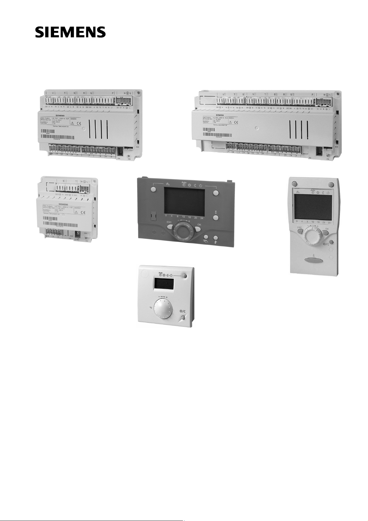
Albatros
Boiler controller
RVS43..
RVS63..
AVS75..
AVS37..
QAA75..
QAA78..
User Manual
Edition 3.0
Controller series B
CE1U2354en
23. August 2007
QAA55..
Building Technologies
HVAC Products
Page 2

2/180
Siemens Schweiz AG User Manual CE1U2354en
HVAC Products 23. August 2007
Page 3

Contents
1 Summary ......................................................................................................... 9
1.1 Type summary............................................................................................... 10
1.1.1 Topology........................................................................................................ 10
2 Safety notes................................................................................................... 12
2.1 Product liability ..............................................................................................12
3 Mounting and installation............................................................................... 13
3.1 Regulations.................................................................................................... 13
Electrical installation ......................................................................................13
3.2 Basic units RVS… ......................................................................................... 13
Engineering ...................................................................................................13
Mounting method........................................................................................... 14
Dimensions and drilling plan.......................................................................... 14
3.2.1 Connection terminals of RVS43.143 .............................................................15
3.2.2 Connection terminals of RVS63.243 .............................................................15
3.2.3 Connection terminals of RVS63.283 .............................................................16
Terminal markings ......................................................................................... 17
3.3 Extension module AVS75.390....................................................................... 19
Dimensions and drilling plan.......................................................................... 19
3.3.1 Connection terminals of AVS75.390.............................................................. 19
Terminal markings ......................................................................................... 20
Assignment of terminals ................................................................................ 20
3.4 Operator unit AVS37.294 ..............................................................................21
Connections................................................................................................... 21
Ground........................................................................................................... 21
3.5 Operator unit AVS37.390 ..............................................................................22
Connections................................................................................................... 22
Dimensions.................................................................................................... 22
3.6 Room unit QAA55… ...................................................................................... 23
Engineering ...................................................................................................23
Mounting method........................................................................................... 23
Connections................................................................................................... 23
Dimensions and drilling plan.......................................................................... 23
3.7 Room unit QAA75… ...................................................................................... 24
Engineering ...................................................................................................24
Mounting method........................................................................................... 24
Connections................................................................................................... 24
Dimensions and drilling plan.......................................................................... 25
3.8 Wireless components .................................................................................... 26
3.8.1 Radio module AVS71.390 ............................................................................. 26
Engineering ...................................................................................................26
Mounting method........................................................................................... 26
Terminals....................................................................................................... 26
Radio connection........................................................................................... 26
Dimensions and drilling plan.......................................................................... 26
3/180
Siemens Schweiz AG User Manual CE1U2354en
HVAC Products 23. August 2007
Page 4

3.8.2 Room unit QAA78.610 ...................................................................................27
Engineering....................................................................................................27
Mounting with base........................................................................................27
Connection / power supply.............................................................................28
Radio connection ...........................................................................................28
Dimensions and drilling plan ..........................................................................29
3.8.3 Wireless outside sensor AVS13.399..............................................................30
Mounting method ...........................................................................................30
Radio connection ...........................................................................................31
Dimensions and drilling plan ..........................................................................31
3.8.4 Radio repeater AVS14.390 ............................................................................32
Mounting method ...........................................................................................32
Connections ...................................................................................................32
Radio connection ...........................................................................................32
Dimensions and drilling plan ..........................................................................32
3.8.5 Checking the wireless components ...............................................................33
3.9 Power supply AVS16.290 ..............................................................................33
Mounting notes ..............................................................................................33
Connections ...................................................................................................33
4 Commissioning ..............................................................................................35
4.1 Basic units......................................................................................................35
5 Handling.........................................................................................................36
5.1 QAA75.. / QAA78… / AVS37.. .......................................................................36
5.1.1 Operation .......................................................................................................36
Operating elements........................................................................................36
Display options...............................................................................................37
Selection of space heating mode...................................................................37
Selection of cooling mode..............................................................................38
Selecting the DHW heating mode..................................................................38
Adjusting the room temperature setpoint .......................................................38
Presence button.............................................................................................39
Displaying information....................................................................................39
5.1.2 Programming .................................................................................................41
Setting principle .............................................................................................41
Example: “Setting the time of day“.................................................................41
5.1.3 User levels .....................................................................................................42
Setting the structure “End user“ .....................................................................43
Setting the structure ”Heating engineer“ ........................................................43
5.1.4 Overview of settings.......................................................................................44
5.2 AVS37.390.....................................................................................................65
5.2.1 Operation .......................................................................................................65
Operating elements........................................................................................65
Display options...............................................................................................65
Selecting the operating mode ........................................................................65
Adjusting the room temperature setpoint .......................................................66
Adjusting the nominal DHW setpoint .............................................................66
Displaying information....................................................................................66
Setting principle .............................................................................................67
Example: “Setting the time of day“.................................................................67
4/180
Siemens Schweiz AG User Manual CE1U2354en
HVAC Products 23. August 2007
Page 5

5.2.2 User levels..................................................................................................... 68
5.2.3 Overview of settings ...................................................................................... 69
5.3 QAA55... ........................................................................................................ 70
5.3.1 Operation....................................................................................................... 70
Operating elements ....................................................................................... 70
Display options .............................................................................................. 70
Selection of space heating mode ..................................................................70
Adjusting the room temperature setpoint....................................................... 71
Presence button ............................................................................................71
5.3.2 Programming ................................................................................................. 72
6 The settings in detail...................................................................................... 73
6.1 Time of day and date..................................................................................... 73
6.2 Operator unit.................................................................................................. 73
Operation and display.................................................................................... 73
Heating circuit assignment ............................................................................75
Room sensor ................................................................................................. 75
Device data.................................................................................................... 75
6.3 Radio ............................................................................................................. 76
Binding........................................................................................................... 76
List of wireless devices.................................................................................. 76
6.4 Time programs ..............................................................................................76
Switching points............................................................................................. 77
Standard program.......................................................................................... 77
6.5 Holidays......................................................................................................... 77
6.6 Heating circuits .............................................................................................. 77
Operating mode............................................................................................. 77
Setpoints........................................................................................................ 78
Heating curve ................................................................................................78
ECO functions ...............................................................................................79
Flow temperature setpoint limits.................................................................... 80
Room influence.............................................................................................. 81
Room temp limitation..................................................................................... 82
Boost heating................................................................................................. 82
Quick setback ................................................................................................ 83
Optimum start / stop control ..........................................................................84
Raising the reduced setpoint ......................................................................... 84
Overtemp prot pump circuit ........................................................................... 85
Mixing valve control ....................................................................................... 85
Floor curing function ...................................................................................... 86
Excess heat draw .......................................................................................... 87
Buffer storage tank / primary controller .........................................................87
Speed-controlled pump .................................................................................87
Remote control .............................................................................................. 87
6.7 Cooling circuit ................................................................................................ 88
Operating mode............................................................................................. 88
Setpoints........................................................................................................ 88
Release .........................................................................................................88
Cooling curve................................................................................................. 89
ECO............................................................................................................... 89
Summer compensation.................................................................................. 89
5/180
Siemens Schweiz AG User Manual CE1U2354en
HVAC Products 23. August 2007
Page 6

Flow temperature setpoint limits ....................................................................90
Room influence ..............................................................................................91
Room temp limitation .....................................................................................91
Mixing valve control .......................................................................................92
Dewpoint monitoring ......................................................................................93
Buffer storage tank / primary controller..........................................................94
Remote control...............................................................................................94
6.8 DHW ..............................................................................................................95
Setpoints ........................................................................................................95
Priority............................................................................................................95
Legionella function .........................................................................................95
Circulating pump ............................................................................................96
6.9 H.. pumps.......................................................................................................96
H.. pumps.......................................................................................................96
6.10 Swimming pool...............................................................................................97
Setpoints ........................................................................................................97
Priority............................................................................................................97
Plant hydraulics..............................................................................................98
6.11 Primary controller / system pump ..................................................................98
Primary controller / system pump ..................................................................98
6.12 Boiler..............................................................................................................98
Operating mode .............................................................................................98
Setpoints ........................................................................................................98
Minimum limitation of the return temperature ................................................99
Output data ....................................................................................................99
2 x 1 cascade...............................................................................................100
6.13 Cascade.......................................................................................................100
Control .........................................................................................................100
Boiler sequence ...........................................................................................100
Minimum limitation of the return temperature ..............................................101
6.14 Solar.............................................................................................................102
Charging controller (dT) ...............................................................................102
Priority..........................................................................................................102
Start function................................................................................................103
Frost protection for the collector ..................................................................104
Overtemperature protection for the collector ...............................................104
Medium’s evaporation temperature .............................................................104
Speed control...............................................................................................104
Yield measurement ......................................................................................105
6.15 Solid fuel boiler ............................................................................................105
Operating mode ...........................................................................................105
Setpoints ......................................................................................................105
Boiler / burner control...................................................................................105
6.16 Buffer storage tank.......................................................................................106
Automatic locks............................................................................................106
Stratification protection ................................................................................107
Overtemperature protection .........................................................................108
Recooling .....................................................................................................108
Plant hydraulics............................................................................................108
Return diversion...........................................................................................108
Partial charging ............................................................................................109
Cooling.........................................................................................................110
6/180
Siemens Schweiz AG User Manual CE1U2354en
HVAC Products 23. August 2007
Page 7

6.17 DHW storage tank ....................................................................................... 110
Charging control .......................................................................................... 110
Overtemperature protection......................................................................... 110
Recooling..................................................................................................... 110
Electric immersion heater ............................................................................ 111
Plant hydraulics ........................................................................................... 112
Speed-controlled pump ...............................................................................112
6.18 Instantaneous DHW heater ......................................................................... 112
Setpoints...................................................................................................... 112
Mixing valve control ..................................................................................... 113
6.19 Configuration ............................................................................................... 113
Heating circuits ............................................................................................ 113
DHW sensor B3........................................................................................... 114
DHW control element Q3............................................................................. 114
Separate DHW circuit .................................................................................. 115
Boiler ...........................................................................................................115
Solar ............................................................................................................ 118
Output relay QX........................................................................................... 119
Input sensor BX ........................................................................................... 122
Input H1 for RVS43.. ...................................................................................123
Input H.. for RVS63.. ..................................................................................128
Input EX2..................................................................................................... 131
Mixing valve groups basic unit..................................................................... 132
Extension module ........................................................................................ 133
QX extension module .................................................................................. 134
BX extension module................................................................................... 135
H2 extension module................................................................................... 135
10V output UX ............................................................................................. 136
Types of sensor/readjustment ..................................................................... 136
Building and room model............................................................................. 137
Frost protection for the plant........................................................................ 137
External requirements .................................................................................137
Sensor state ................................................................................................138
Parameter reset........................................................................................... 138
Plant diagram ..............................................................................................138
Device data.................................................................................................. 141
6.20 LPB.............................................................................................................. 141
Address / power supply ............................................................................... 141
Central functions.......................................................................................... 141
Clock............................................................................................................ 143
6.21 Faults........................................................................................................... 143
6.22 Maintenance/special mode.......................................................................... 144
Maintenance functions................................................................................. 144
Chimney sweep ........................................................................................... 144
Manual operation......................................................................................... 145
Simulations .................................................................................................. 146
Telephone customer service .......................................................................146
6.23 Input / output test......................................................................................... 146
6.24 State ............................................................................................................ 147
Messages .................................................................................................... 147
6.25 Diagnostics, heat generation ....................................................................... 150
6.26 Diagnostics, consumers ..............................................................................150
7/180
Siemens Schweiz AG User Manual CE1U2354en
HVAC Products 23. August 2007
Page 8

6.27 List of displays .............................................................................................151
6.27.1 Error code ....................................................................................................151
6.27.2 Maintenance code........................................................................................152
6.27.3 Special operation code ................................................................................152
7 Plant diagrams .............................................................................................153
7.1 Basic diagrams ............................................................................................153
7.1.1 Basic diagram RVS43.143...........................................................................153
7.1.2 Basic diagram RVS63.243...........................................................................154
7.1.3 Basic diagram RVS63.283...........................................................................155
7.2 Versions of heat sources .............................................................................156
7.3 Extra functions in general ............................................................................157
Solar.............................................................................................................157
Boiler............................................................................................................159
DHW storage tank (DHW)............................................................................160
Heating/cooling circuit..................................................................................161
Heat converter .............................................................................................162
Swimming pool.............................................................................................162
Pressureless header ....................................................................................162
Extra functions .............................................................................................162
7.4 Additional funct. with mix. valve group or extension module AVS75.390 ....163
Legend mains voltage..................................................................................166
Legend low-voltage......................................................................................167
8 Technical data..............................................................................................168
8.1 Basic units RVS…........................................................................................168
8.2 Extension module AVS75.390 .....................................................................169
8.3 Operator unit and room units AVS37... / QAA7x… / QAA55.. .....................170
8.4 Power supply AVS16.290 ............................................................................171
8.5 Radio module AVS71.390............................................................................171
8.6 Wireless outside sensor AVS13.399............................................................172
8.7 Radio repeater AVS14.390 ..........................................................................173
8.8 Sensor characteristics..................................................................................174
8.8.1 NTC 1 k........................................................................................................174
8.8.2 NTC 10 k......................................................................................................175
8.8.3 PT1000 ........................................................................................................175
9 Revision history............................................................................................179
8/180
Siemens Schweiz AG User Manual CE1U2354en
HVAC Products 23. August 2007
Page 9

1 Summary
The present User Manual describes the products listed in the following table and covers
handling and configuration of the controls for readers ranging from end users to heating
engineers.
Type reference
(ASN)
RVS43.143 B Basic unit boiler
RVS63.243 B Basic unit boiler
RVS63.283 B Basic unit boiler
AVS75.390 B Extension module
AVS37.294 B operator unit
AVS37.390 A Operator unit basic
QAA75.610 B Room unit, wired
QAA75.611 B Room unit with backlight, wired
QAA78.610 B Room unit, wireless
QAA55.110 A Room unit basic
AVS16.290 A Power section
AVS71.390 A Radio module
AVS14.390 A Radio repeater
AVS13.399 A Wireless outside sensor
The following products are described in separate pieces of documentation:
QAC34 Outside sensor NTC 1 kΩ
QAD36 Strap-on temperature sensor NTC 10 kΩ
QAZ36 Immersion temperature sensor NTC 10 kΩ
Series Name
9/180
Siemens Schweiz AG User Manual CE1U2354en
HVAC Products Type summary 23. August 2007
Page 10
Wired
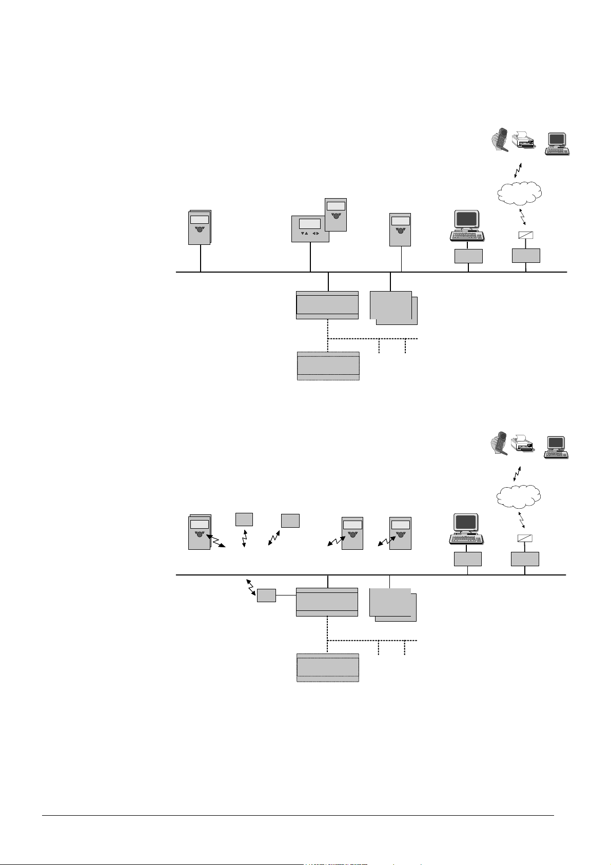
1.1 Type summary
1.1.1 Topology
Mobile, SMS, Pager, Fax,
WEB,
Remote
Wireless
Room
Unit
wired
BSB-W
HMI
Basic Unit
HMI
(RU)
wired
RVSxx
LPB
Basic Unit
RVS...
Service Unit
(RU)
wired
Extension
mod. AVS75…
(max. 2)
Service Tool
ACS700
OCI700
Telephone
Network
Telephone
SMS
OCI611
BSB :
Boiler System Bus
LPB : Local Process Bus
Mobile, SMS, Pager, Fax,
WEB,
Remote
Room
Unit
wireless
BSB-W
RF
Toutside
BSB-RF
RF
module
RF
Repeater
Basic Unit
RVSxx
LPB
Basic Unit
RVS...
HMI
(RU)
wireless
Service Unit
(RU)
wireless
Extension
mod. AVS75…
(max. 2)
Service Tool
ACS700
OCI700
Telephone
Network
Telephone
SMS
OCI611
BSB :
Boiler System Bus
LPB : Local Process Bus
10/180
Siemens Schweiz AG User Manual CE1U2354en
HVAC Products Type summary 23. August 2007
Page 11

Operation with room
unit
Operating options
Wired Wireless
Operation with “basic”
operator unit
(optionally with additional
room unit)
Operation with “clear-text”
operator unit
(optionally with additional room
unit)
B
A
D
T
B
A
E1
EB
C
T
2359Z66
B
A
D
B
A
B
F
E1
E
C
2359Z67
A
A Basic unit RVS…
B Power section AVS16…
C Room unit QAA75… / 78… / QAA55..
D Outside sensor AVS13…
E Operator unit AVS37.294 (clear-text)
E1 Operator unit AVS37.390 (basic)
F Radio module AVS71…
A
11/180
Siemens Schweiz AG User Manual CE1U2354en
HVAC Products Type summary 23. August 2007
Page 12

2 Safety notes
2.1 Product liability
• The products may only be used in building services plant and applications as
described above
• When using the products, all requirements specified in the chapters on "Handling"
and "Technical data" must be satisfied
• Local regulations (for installation, etc.) must be complied with
• Do not open the units. If not observed, warranty becomes void.
12/180
Siemens Schweiz AG User Manual CE1U2354en
HVAC Products Product liability 23. August 2007
Page 13

Electrical installation
Engineering
Mounting location
3 Mounting and installation
3.1 Regulations
• Prior to installing the controller, the power supply must be turned off
• The connections for mains and low-voltage are separated
• The wiring must be made in compliance with the requirements of safety class II. This
means that sensor and mains cables may not be run in the same duct
3.2 Basic units RVS…
• Air circulation around the controller must be ensured, allowing the unit to emit the
heat produced by it.
A clearance of at least 10 mm must be provided for the controller's cooling slots
which are situated a the top and bottom of the housing.
The space should not be accessible and no objects should be placed there. If the
controller is enclosed in another (insulating) casing, a clearance of up to 100 mm
must be observed around the cooling slots
• The controller is designed conforming to the directives for safety class II mounted in
compliance with these regulations.
• Power to the controller may only be supplied when completely fitted. If this is not
observed, there is a risk of electric shock hazard near the terminals and through the
cooling slots.
• The controller may not be exposed to dripping water.
• Permissible ambient temperature when mounted and when ready to
operate: 0..50°C.
• Power cables must be clearly segregated from low-voltage cables (sensors)
observing a distance of at least 100 mm
• Boiler
• Control panel
• Housing for wall mounting
13/180
Siemens Schweiz AG User Manual CE1U2354en
HVAC Products Regulations 23. August 2007
Page 14
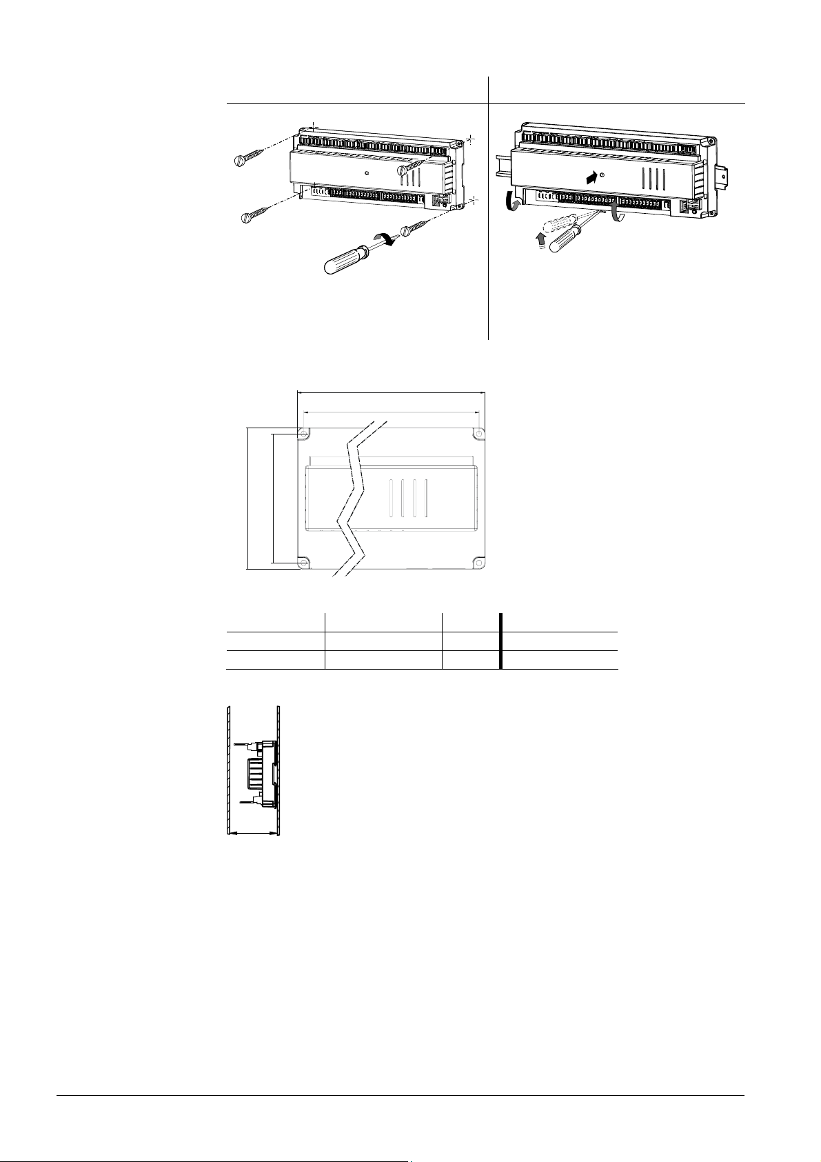
Mounting method
Screwed
On DIN rail
Dimensions and drilling plan
BL1B1
A2
A1
2359Z09
L
B1
A: Mounting / B: Removal
Note:
To mount the controller on a DIN rail, a mounting clip
is required!
B2
Dimensions in mm
2359Z11
Total height required
RVS63…
RVS43…
2359Z10
x
2358M01
L B H L1 B1
281 121 52 270 110
181 121 52 170 110
Dimension X:
Connectors with tongues minimum 70 mm
Connector without tongues minimum 60 mm
14/180
Siemens Schweiz AG User Manual CE1U2354en
HVAC Products Basic units RVS… 23. August 2007
Page 15
3.2.1 Connection terminals of RVS43.143
050110A
000020RVS43.143/109
S05011000002 0
1PRVS13.143/109
2354Z08
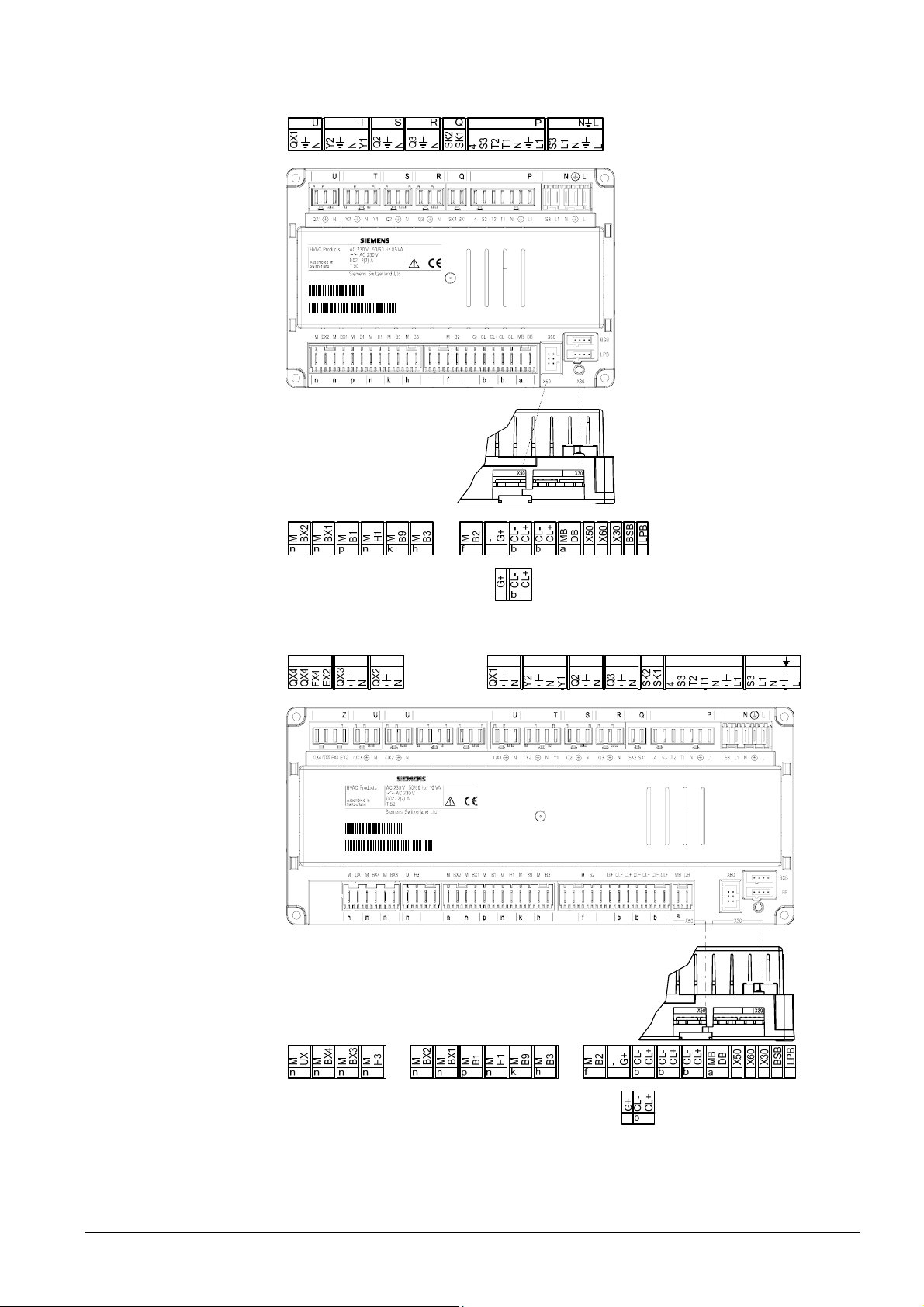
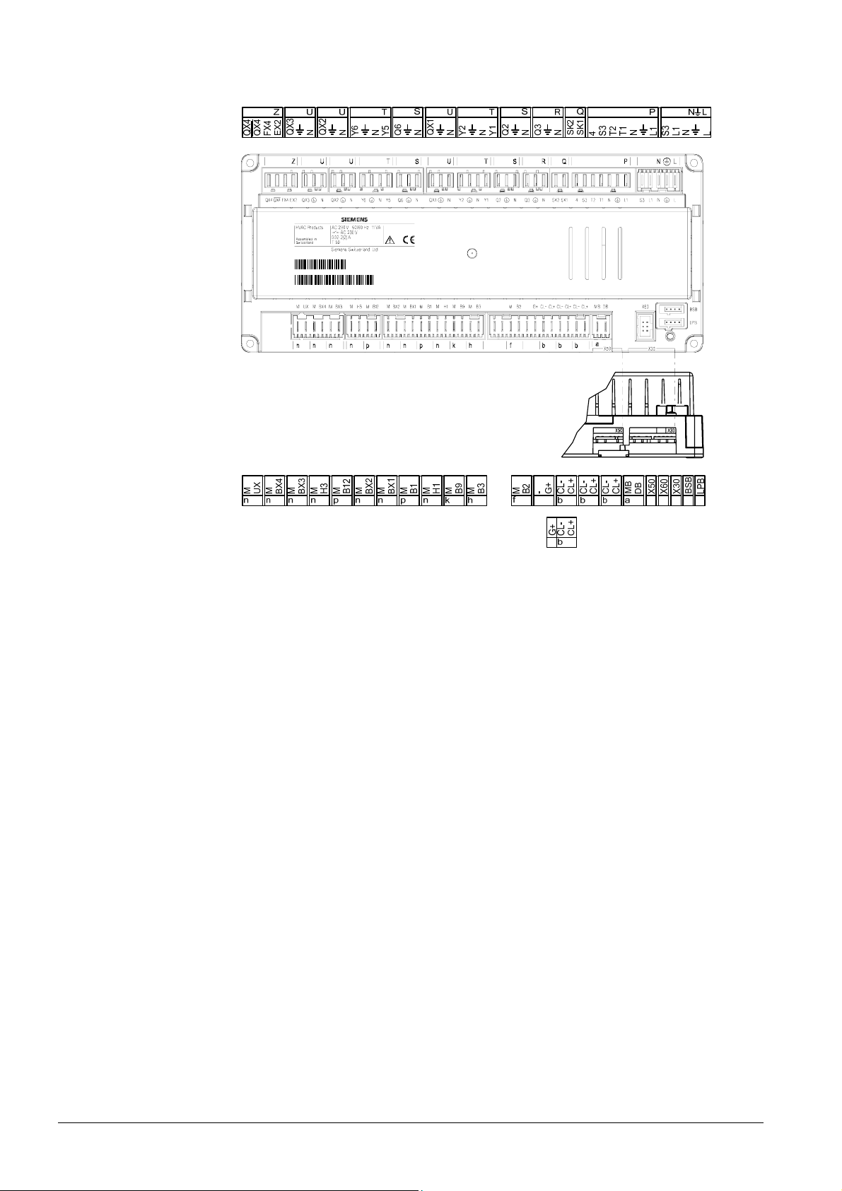
3.2.2 Connection terminals of RVS63.243
Z
U U
U
061107B
000020RVS63.243/10 9
S061107000020
1PRVS63.243/109
T
S R Q
P LN
2354Z06
15/180
Siemens Schweiz AG User Manual CE1U2354en
HVAC Products Basic units RVS… 23. August 2007
Page 16
3.2.3 Connection terminals of RVS63.283
061107B
000020RVS63.283/10 9
S061107000020
1PRVS63.283/109
2354Z07
16/180
Siemens Schweiz AG User Manual CE1U2354en
HVAC Products Basic units RVS… 23. August 2007
Page 17

Terminal markings
Mains voltage
Use Slot Connector type
L Live AC 230 V basic unit N L AGP4S.05A/109
Protective earth
N Neutral conductor
L1 Live AC 230 V burner
S3 Output burner fault
L1 Phase burner P AGP8S.07A/109
Protective earth
N Neutral conductor
T1 Phase 1st burner stage
T2 1st burner stage on
S3 Input burner fault
4 Input 1st burner stage operating hours
SK1 Safety loop Q AGP8S.02E/109
SK2 Safety loop
N Neutral conductor R AGP8S.03A/109
Protective earth
Q3 DHW charging pump / diverting valve
N Neutral conductor S AGP8S.03B/109
Protective earth
Q2
Y1
1st heating circuit pump
1st heating circuit mixing valve opening
N Neutral conductor
Protective earth
Y2 1st heating circuit mixing valve closing
T AGP8S.04B/109
N Neutral conductor U AGP8S.03C/109
Protective earth
QX1 Multifunctional output 1
N Neutral conductor S AGP8S.03B/109
Protective earth
Q6 2nd heating circuit pump
Y5 2nd heating circuit mixing valve opening T AGP8S.04B/109
N Neutral conductor
Protective earth
Y6 1st heating circuit mixing valve closing
N Neutral conductor U AGP8S.03C/109
Protective earth
QX2 Multifunctional output 2
N Neutral conductor U AGP8S.03C/109
Protective earth
QX3 Multifunctional output 3
EX2 Multifunctional input Z AGP8S.04C/109
FX4
(T6)
QX4
(T7)
QX4
(T8)
Multifunctional output 4
(phase 2nd burner stage)
Multifunctional output 4 off
(2nd burner stage off)
Multifunctional output 4 on
(2nd burner stage on)
17/180
Siemens Schweiz AG User Manual CE1U2354en
HVAC Products Basic units RVS… 23. August 2007
Page 18

Low voltage
Use Slot Connector type
BSB Service tool OCI700 - LPB Service tool OCI700 - X60 Radio module AVS71.390 - X50 Extension module AVS75.390 X30 Operator unit / boiler control panel -
DB LPB data
MB LPB ground
CL+ BSB data
AVS82.490/109
AVS82.491/109
AGP4S.02H/109
AGP4S.02A/109
CL- BSB ground b
CL+ Room unit 2 data
AGP4S.02A/109
CL- Room unit 2 ground b
CL+ Room unit 1 data
AGP4S.02A/109
CL- Room unit 1 ground b AGP4S.03D/109
G+ Room unit power supply 12 V
B2 Boiler sensor
AGP4S.02B/109
M Ground f
B3 DHW sensor top
AGP4S.02C/109
M Ground h
B9 Outside sensor
AGP4S.02D/109
M Ground k
H1 Digital / DC 0...10 V input
AGP4S.02F/109
M Ground n
B1 Flow temperature sensor HK1
AGP4S.02G/109
M Ground p
BX1 Multifunctional sensor input 1 AGP4S.02F/109
M Ground n
BX2 Multifunctional sensor input 2 AGP4S.02F/109
M Ground n
B12 Flow temperature sensor HK2
AGP4S.02G/109
M Ground p
H3 Digital / DC 0...10 V input
AGP4S.02F/109
M Ground n
BX3 Multifunctional sensor input 3
AGP4S.02F/109
M Ground n
BX4 Multifunctional sensor input 4
AGP4S.02F/109
M Ground n
UX DC 0…10 V output n AGP4S.02F/109
M Ground
18/180
Siemens Schweiz AG User Manual CE1U2354en
HVAC Products Basic units RVS… 23. August 2007
Page 19
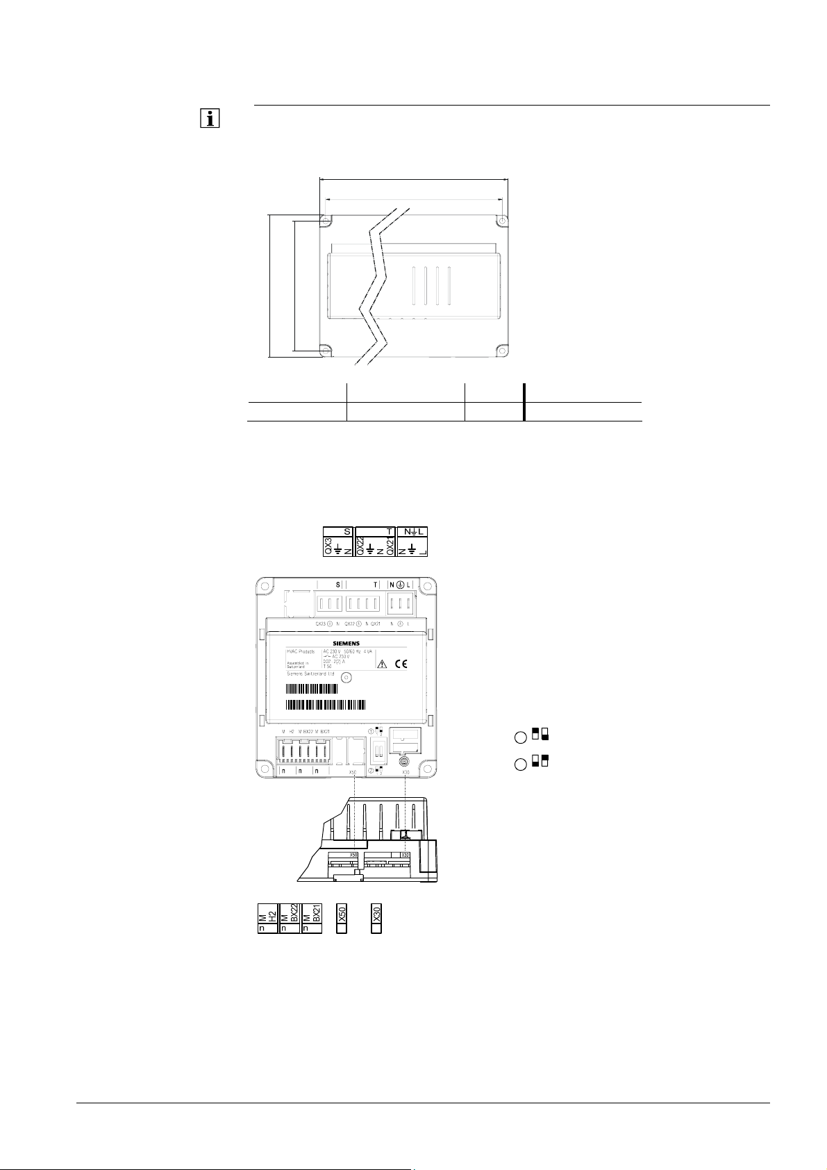
Dimensions and drilling plan
Connections
3.3 Extension module AVS75.390
For planning, mounting location and mounting method, refer to the information given for
the basic modules.
L
Dimensions in mm
BL1B1
2358M01
AVS75.390
The AVS75.390 extension module is connected to terminal
the
AVS83.490/109 connecting cable. The connectors are coded.
L B H L1 B1
108.7 120.9 51.7 98 110
X50 of the basic unit using
3.3.1 Connection terminals of AVS75.390
050110A
AVS75.390/109
S050110000020
1PAVS75.390/109
000020
1
2359Z49
2
12
1
2
= Module 1
= Module 2
19/180
Siemens Schweiz AG User Manual CE1U2354en
HVAC Products Extension module AVS75.390 23. August 2007
Page 20
Terminal markings
Mains voltage
Low voltage
Assignment of terminals
Use Slot Connector type
L Live AC 230 V basic unit N L AGP4S.03E/109
Protective earth
N Neutral conductor
QX21 Assignment according to function T AGP8S.04B/109
N Neutral conductor
Protective earth
QX22 Assignment according to function
N Neutral conductor S AGP8S.03B/109
Protective earth
QX23 Assignment according to function
Use Space Connector type
X30 Operator unit / boiler control panel X50 Basic unit
AVS82.491/109
AVS82.490/109
BX21 Assignment according to function AGP4S.02F/109
M Ground n
BX22 Assignment according to function AGP4S.02F/109
M Ground n
H2 Digital / DC 0...10 V input AGP4S.02F/109
M Ground n
The two following parameters define the usage of the respective module:
• Function extension module 1 (operating line 6020)
• Function extension module 2 (operating line 6021)
.
20/180
Siemens Schweiz AG User Manual CE1U2354en
HVAC Products Extension module AVS75.390 23. August 2007
Page 21
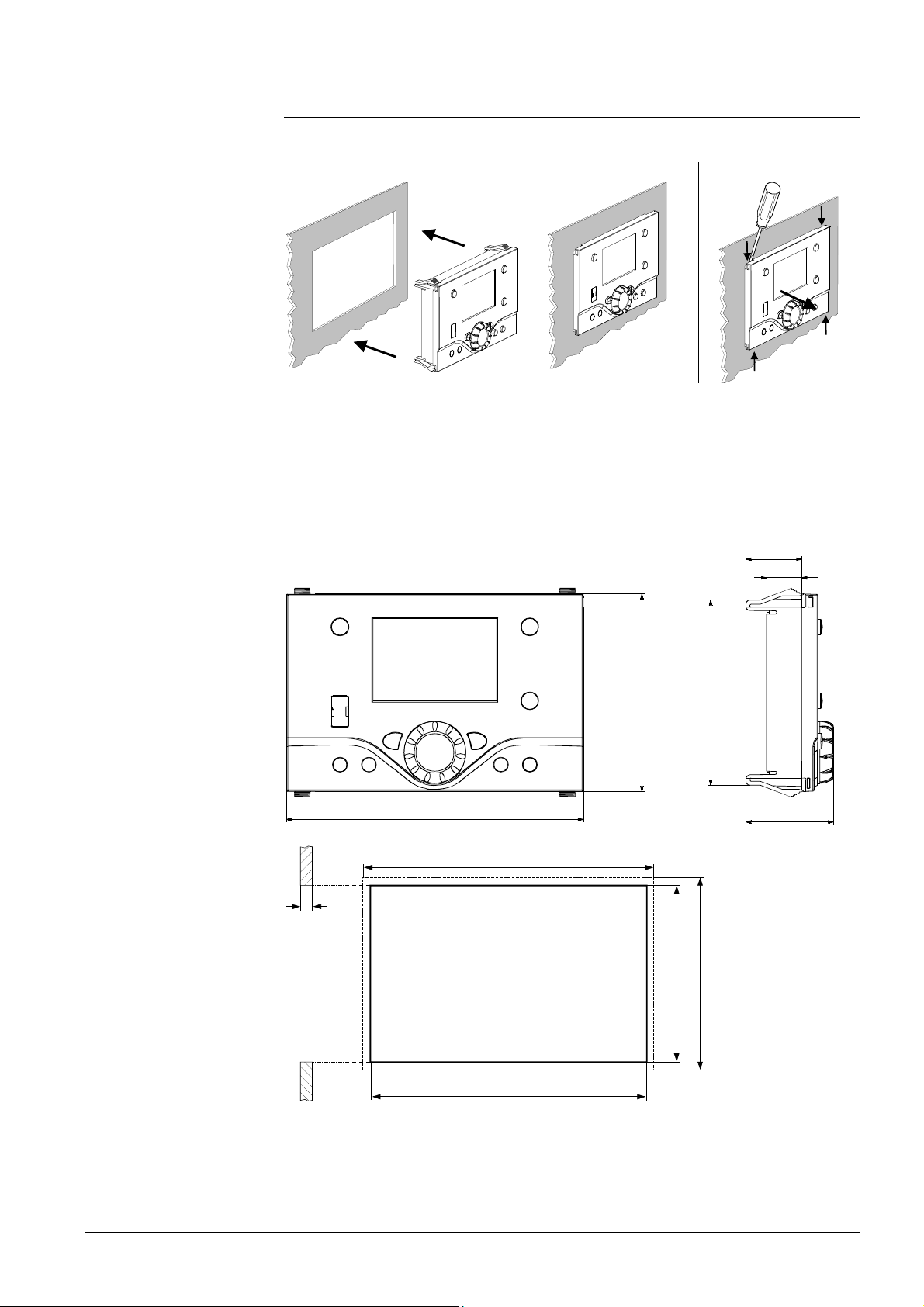
3.4 Operator unit AVS37.294
Mounting method
Installation
2358Z30
Removal
2358Z31
2358Z32
Connections
Ground
Panel cutout
The AVS37.294 operator unit must be connected to terminal X30 of the basic unit using
the AVS82.491/109 connecting cable. The connectors are coded.
27
17
2358M03
96
144
90
42.4
(144)
0.5...3.0
0
+0.8
92
(96)
+1
138
0
2358M05
21/180
Siemens Schweiz AG User Manual CE1U2354en
HVAC Products Operator unit AVS37.294 23. August 2007
Page 22
Connections
Dimensions
3.5 Operator unit AVS37.390
The AVS37.390 operator unit must be connected to terminal X30 of the basic unit using
the AVS82.491/109 connecting cable. The connectors are coded.
2354M01
0,5
13
A
A Control panel, front
22/180
Siemens Schweiz AG User Manual CE1U2354en
HVAC Products Operator unit AVS37.390 23. August 2007
Page 23
Engineering
Mounting method
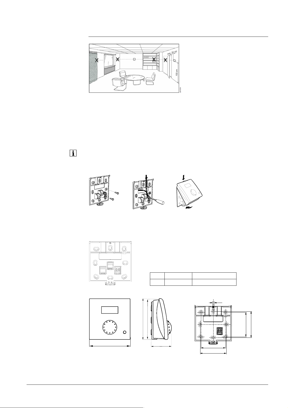
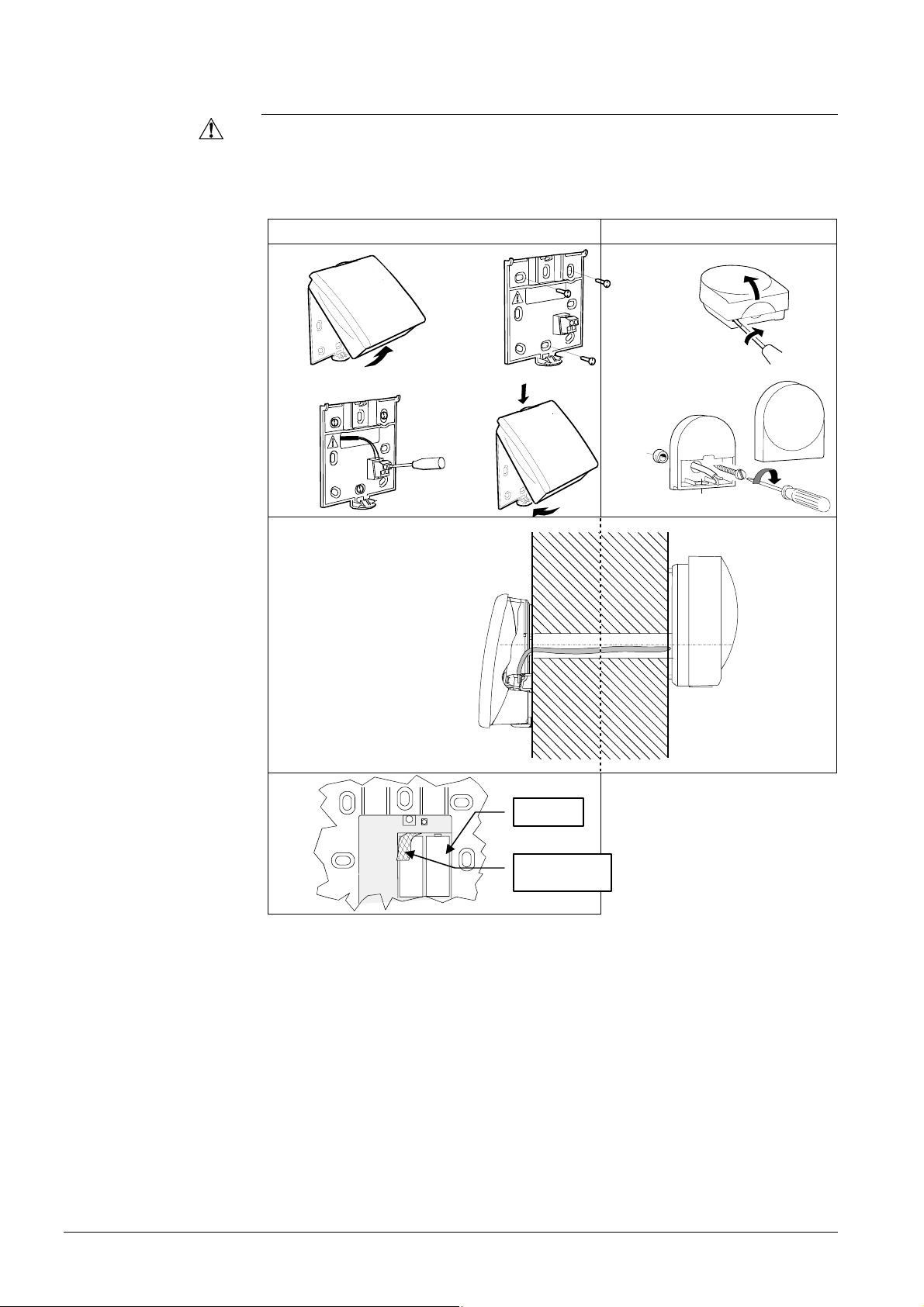
3.6 Room unit QAA55…
@
The room unit should be located in the main living room while giving consideration to
the following points:
• The place of installation should be chosen so that the sensor can capture the room
temperature as accurately as possible without getting adversely affected by direct
solar radiation or other heat or refrigeration sources (about 1.5 meters above the floor)
• In the case of wall mounting, there must be sufficient clearance above the unit,
enabling it to be fitted and removed
When the unit is removed from its base, power is cut off so that the unit is out of
operation.
2284Z33a
2284Z34a
Connections
Dimensions and drilling plan
• The controller must not be exposed to dripping water
34
562
1
2284Z40
1 CL+ BSB data
2 CL- BSB ground
2282M02
1
6
9
9
96
7
4
4,2
56
12
56
60
2359Z27
60
23/180
Siemens Schweiz AG User Manual CE1U2354en
HVAC Products Room unit QAA55… 23. August 2007
Page 24
Engineering
Mounting method
3.7 Room unit QAA75…
@
The room unit should be located in the main living room while giving consideration to
the following points:
• The place of installation should be chosen so that the sensor can capture the room
temperature as accurately as possible without getting adversely affected by direct
solar radiation or other heat or refrigeration sources (about 1.5 meters above the floor)
• In the case of wall mounting, there must be sufficient clearance above the unit,
enabling it to be fitted and removed
When the unit is removed from its base, power is cut off so that the unit is out of
operation.
Connections
2359Z25
2359Z20
2359Z26
2359Z24
Terminal Name QAA75.610 QAA75.611
1 CL+ BSB data BSB data
2 CL- BSB ground BSB ground
3 G+ Reserved Power supply DC 12 V
2359Z21
24/180
Siemens Schweiz AG User Manual CE1U2354en
HVAC Products Room unit QAA75… 23. August 2007
Page 25
Dimensions and drilling plan
4,2
56
60
100
2359Z50
56
60
80
82
42
185
100
2359Z12
25/180
Siemens Schweiz AG User Manual CE1U2354en
HVAC Products Room unit QAA75… 23. August 2007
Page 26
Engineering
Mounting method
3.8 Wireless components
The wireless components should be located such that transmission will be as
interference-free as possible. The following criteria must be observed:
• Not in the vicinity of electrical cables, strong magnetic fields or equipment like PCs,
TV sets, microwave ovens, etc.
• Not near larger metal structures or constructional elements with fine metal meshes
such as special glass or special concrete
• The distance to the transmitter should not exceed 30 meters or 2 floors
3.8.1 Radio module AVS71.390
The radio module extends the product range by introducing wireless communication.
With this type of device, the system components, such as room units, transmit data with
no need for laying cables.
Do not install the radio module inside metal casings (e.g. inside a boiler).
2359Z23
Terminals
Radio connection
Dimensions and drilling plan
LED
A
Button
B
2359Z57
The prefabricated cable is to be connected to terminal X60 of the controller.
Prior to connecting the module, the basic unit must be disconnected from power!
Establishment of the wireless connection is described in the following sections which
cover the relevant radio-controlled units.
2354Z11
43
26/180
Siemens Schweiz AG User Manual CE1U2354en
HVAC Products Wireless components 23. August 2007
Page 27
Engineering
Mounting with base
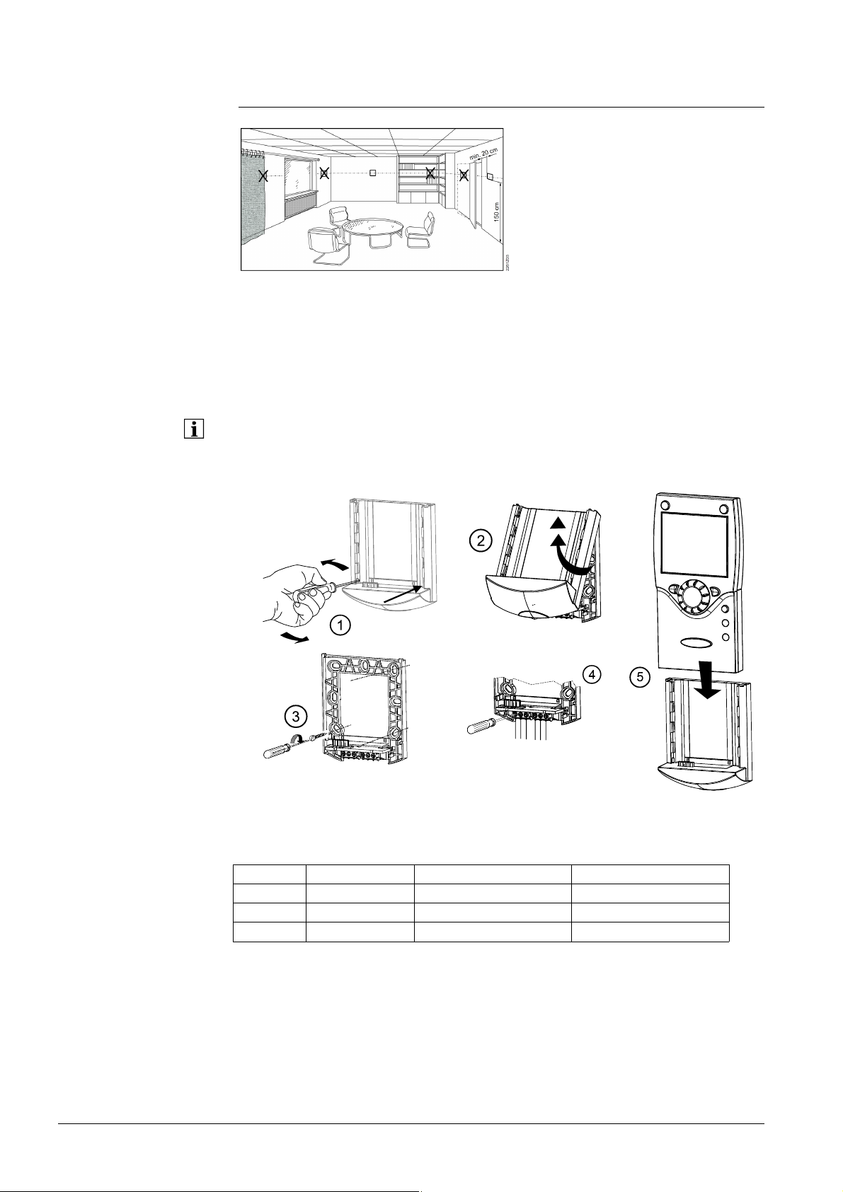
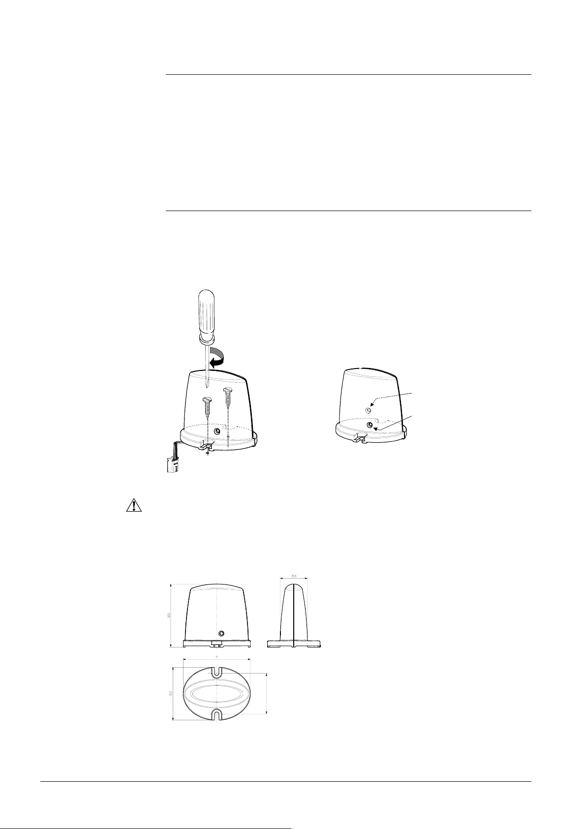
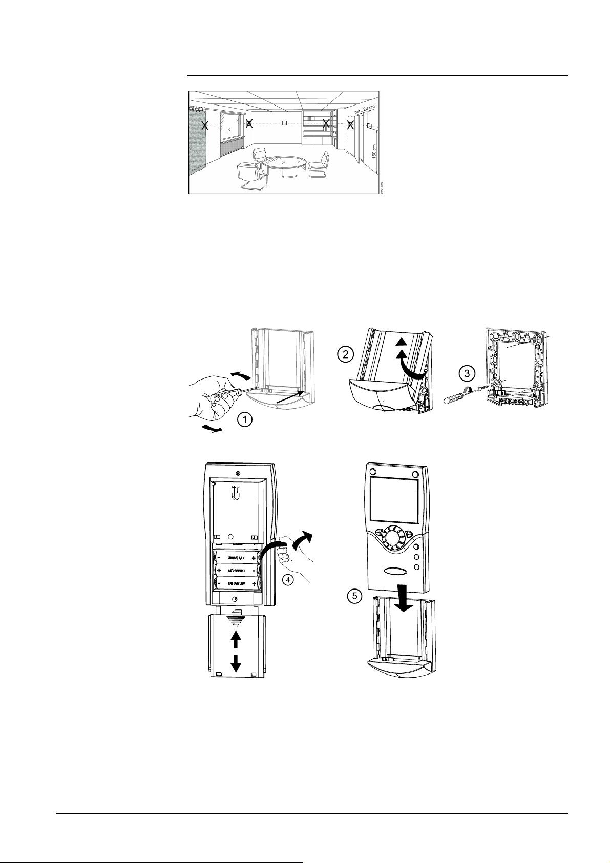
3.8.2 Room unit QAA78.610
@
The room unit should be located in the main living room while giving consideration to
the following points:
• The place of installation should be chosen so that the sensor can capture the room
temperature as accurately as possible without getting adversely affected by direct
solar radiation or other heat or refrigeration sources (about 1.5 meters above the floor)
• In the case of wall mounting, there must be sufficient clearance above the unit,
enabling it to be fitted and removed
2359Z26
2359Z20
2359Z25
2359Z21
2359Z22
27/180
Siemens Schweiz AG User Manual CE1U2354en
HVAC Products Wireless components 23. August 2007
Page 28
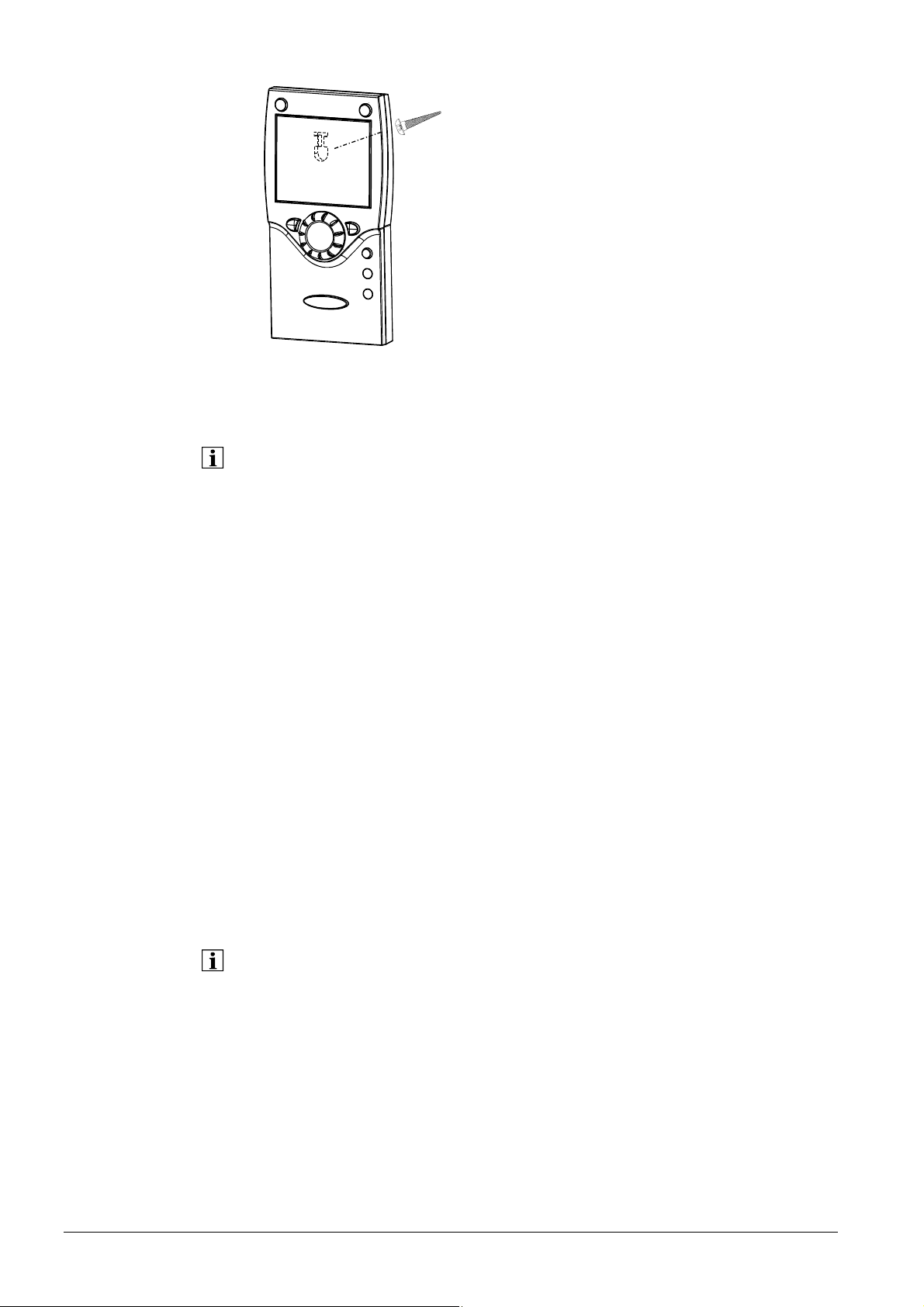
Mounting without base
Connection / power supply
Radio connection
Establishing the link
Testing
2359Z61
The room unit is powered by 3 pieces 1.5 V alkaline batteries type AA (LR06).
Make the radio connection in the vicinity of the radio module prior to mounting so that
all system are within easy reach.
Prerequisite for the radio connection is that all components receive power, which
means that the radio module must be correctly connected to the basic unit and the
batteries must be correctly installed in the room unit.
1. Press the button on the installed radio module for at least 8 seconds until the LED
on the radio module starts flashing at high frequency.
2. Press OK on the room unit to switch to programming.
3. Press the info button for at least 3 seconds and select operating level
“Commissioning“ with the setting knob. Then, press OK.
4. Select operating page “Operator unit“ and press OK.
5. Select operating line “Used as“ (operating line 40) and make the appropriate
selection. Then, press OK.
6. Select operating page “Radio“ and press OK.
7. Select setting line “Binding“ (line 120). Then, press OK.
8. Set the setting knob to “YES“ and press OK. Connection establishment is started.
9. The display shows the progress of connection establishment in %. This process can
take 2 to 120 seconds.
10. The connection is established when “Device ready” appears and the LED on the
radio module extinguishes
The test is made to check the quality of the radio link.
• The test can be aborted by pressing the ESC button.
• While the radio link can be opened on the controller, the test should be made at the
location where the room unit will be installed
On the room unit, as described above (points 2 through 4), select operating page
“Radio“ and activate the test mode on setting line “Test mode“ (line 121).
28/180
Siemens Schweiz AG User Manual CE1U2354en
HVAC Products Wireless components 23. August 2007
Page 29
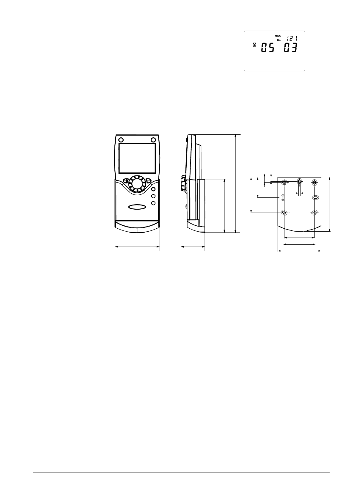
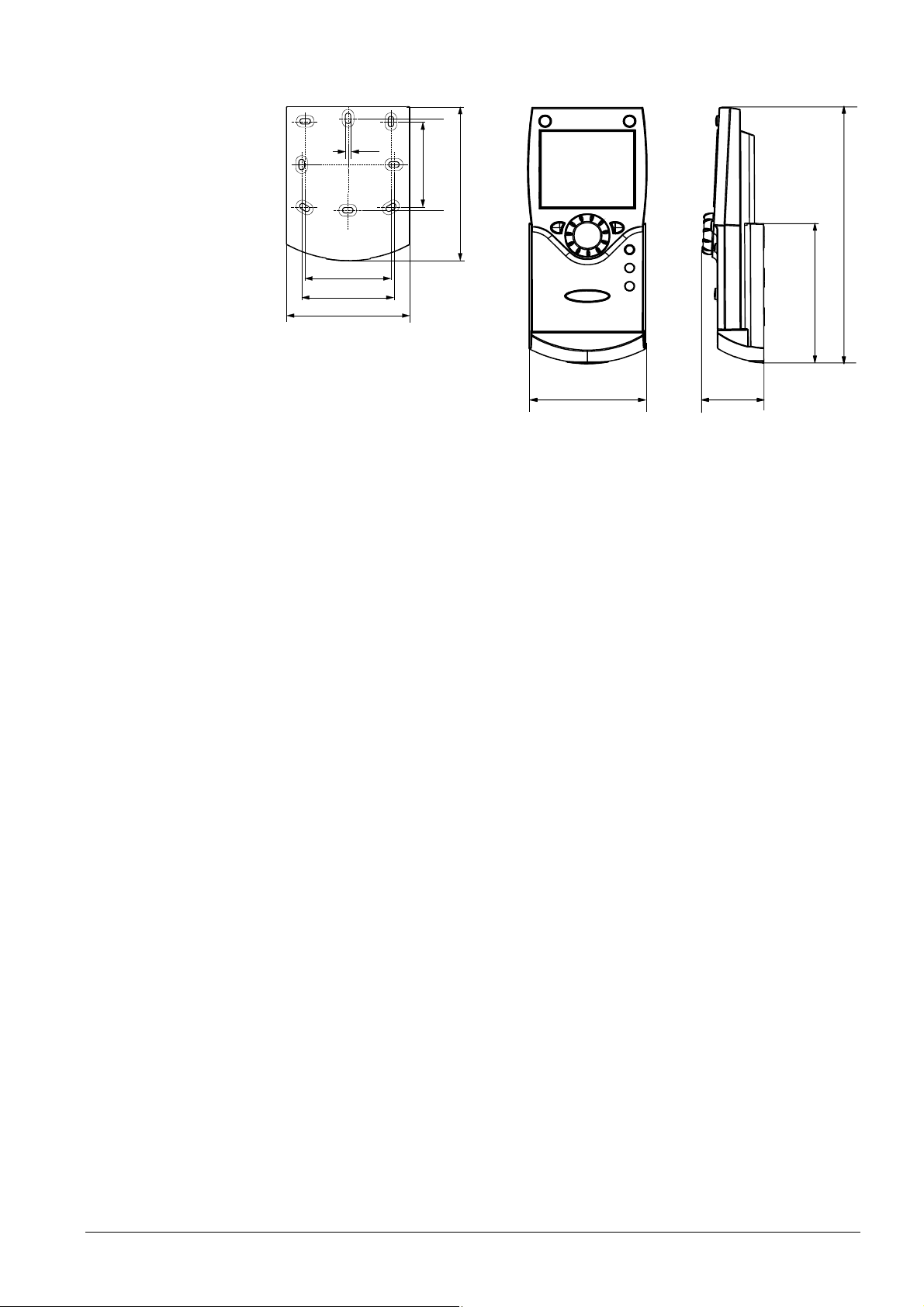
Dimensions and drilling plan
Example of a display during the test:
The digits on the left shows telegrams that have
been sent, the digits on the right telegrams that
have been received. The test will be ended
after 24 telegrams. The test is considered
successful when at least 50 % of the telegrams
Bedieneinheit
Testmode
sent have been received.
If the test was not successful, some other mounting location is to be selected or the
AVS14.390 radio repeater can be used.
9
185
11
39
67
4,2
2359Z50
100
82
42
2359Z12
56
60
80
100
29/180
Siemens Schweiz AG User Manual CE1U2354en
HVAC Products Wireless components 23. August 2007
Page 30
Mounting method
3.8.3 Wireless outside sensor AVS13.399
• The radio transmitter must be installed inside the building.
• The radio transmitter’s mounting location should be chosen such that batteries
can be easily changed.
RF transmitter
2359Z30
2359Z33
Outside sensor
2359Z54
2359Z32
2359Z59
2359Z31
2359Z53
Battery
AAA
AAA
Battery transit
2359Z55
tab
Connections
The outside sensor is to be connected to the radio transmitter via a 2-core cable, the
connections are interchangeable.
The room unit is powered by two 1.5 V alkaline batteries type AAA (LR03).
30/180
Siemens Schweiz AG User Manual CE1U2354en
HVAC Products Wireless components 23. August 2007
Page 31

Radio connection
Establishing the link
Testing
Dimensions and drilling plan
Make the radio connection in the vicinity of the radio module prior to mounting so that
all system are within easy reach.
Prerequisite for the radio connection is that all components receive power, which
means that the radio module must be correctly connected to the basic unit and the
batteries must be correctly installed in the room unit.
1. Press the button on the radio module for at least 8
LED
seconds until the LED on the radio module starts
flashing at high frequency.
2. Press the button on the transmitter of the wireless
AAA
AAA
outside sensor for at least 8 seconds until that LED
also starts flashing at high frequency.
3. The connection is established when the LED on the
radio module extinguishes.
Button
4. Press the button on the transmitter of the wireless outside sensor briefly again until
the LED extinguishes.
The test is made to check the quality of the radio link.
• The test can be aborted by pressing the ESC button.
• While the radio link can be opened on the controller, the test should be made at the
location where the room unit will be installed
1. Press button 3 on the transmitter of the wireless outside sensor for a maximum of 8
seconds until the LED start flashing at low frequency.
2. When radio communication works, the LED on the radio module flashes briefly at
10-second intervals.
3. After the test, press the button on the transmitter of the wireless outside sensor
again briefly until the LED extinguishes.
2359Z58
2359Z16
100
90
4,2
12
56
60
2359Z27
32
56
60
79,8
5,5
4
49,5
2524,5
Ø 14,1
91,6
49,7
3
6
5,5
1811M02
1811M01
31/180
Siemens Schweiz AG User Manual CE1U2354en
HVAC Products Wireless components 23. August 2007
Page 32

Mounting method
Connections
Radio connection
Establishing the link
Testing
Dimensions and drilling plan
3.8.4 Radio repeater AVS14.390
• To establish the radio connection, the device must be provisionally connected to
power prior to mounting, enabling the radio connection to be opened and tested.
• The radio repeater must be fitted inside the building.
1
Power is supplied via the enclosed power pack. The wires are interchangeable.
Make the radio connection in the vicinity of the radio module prior to mounting so that
all system are within easy reach.
Prerequisite for the radio connection is that all components receive power, which
means that the radio module must be correctly connected to the basic unit and power
must be correctly supplied to the radio repeater.
1. Press the button on the radio module for at least 8
seconds until the LED on the radio module starts
flashing at high frequency.
2. Press the button on the installed radio repeater until
the LED start flashing at high frequency.
3. The connection is established when the LED on the
radio module extinguishes.
The test is made to check the quality of the radio link.
• The test can be aborted by pressing the ESC button.
• While the radio link can be opened on the controller, the test should be made at the
location where the room unit will be installed
1. Press button 3 on the radio repeater for a maximum of 8 seconds until the LED
starts flashing at low frequency.
2. When radio communication works, the LED on the radio module flashes briefly at
10-second intervals.
3. After the test, press the button on the radio repeater again briefly until the LED
extinguishes.
2359Z30
2
2359Z33
4
LED
Button
4,2
2359Z16
2359Z31
2359Z56
100
12
90
32/180
Siemens Schweiz AG User Manual CE1U2354en
HVAC Products Wireless components 23. August 2007
32
56
60
2359Z27
56
60
Page 33

Mounting notes
3.8.5 Checking the wireless components
To check whether the connections to the required system components are operational,
consult operating lines 130 through 135 on operating page “Wireless“ (operating level
“Commissioning“).
3.9 Power supply AVS16.290
The boiler control panel is designed for installation in floor-standing or wall-hung oil or
gas boilers and may only be used for that purpose. For installation, the following points
must be observed:
• Power to the control panel may be supplied only after the unit is completely fitted in
the cutout. Extension modules or dummy covers for which cutouts are provided must
also be fitted beforehand.
• Dimensions of cutout 92 x 92 mm,
sheet metal thickness 0.5 to 3.0 mm
• The boiler control panel can be secured with the 4 clips provided on the panel
• Power to the control panel may be supplied only after the unit is completely fitted in
the cutout. Extensions or dummy covers for which cutouts are provided must also be
fitted beforehand.
• The control panel wiring to the connection terminals does not feature strain relief and
must therefore be secured inside the boiler
• The local regulations for electrical installation must be complied with
Mounting method
Installation Removal
2358Z27
2358Z28
2358Z29
Connections
Mains
Terminal Name
L Live AC 230 V blue
Protective earth green + yellow
N Neutral conductor blue
Connection to basic unit
Terminal Name
1 L Live AC 230 V basic unit brown
2
Protective earth green + yellow
3 N Neutral conductor blue
4 L1 Live AC 230 V burner black
5 S3 Input burner fault -
33/180
Siemens Schweiz AG User Manual CE1U2354en
HVAC Products Power supply AVS16.290 23. August 2007
Page 34

Dimensions
S1
1A
3B
2A
4B
Si
1
2
N
L
STB
C2
PE
1A
3B1
1
H1
12345
2358A16
N1L
L1 S3
Mains supply to RVS… basic unit
Si Fuse 6.3AT
S1 Mains switch with green glow lamp
STB = SLT Safety limit thermostat 110°C
H1 Signal lamp‚ SLT has cut out
80
35
0.5...3.0
2358M04
96
96
(96)
92
90
48
0
+0.8
92
(96)
+0.8
0
2358M02
34/180
Siemens Schweiz AG User Manual CE1U2354en
HVAC Products Power supply AVS16.290 23. August 2007
Page 35

Prerequisites
Functional check
Operating state
Diagnosis
4 Commissioning
To commission the units, the following working steps must be carried out:
• Prerequisite is the correct mounting and correct electrical installation and, in the case
of wireless solutions, correctly working radio connections to all required auxiliary units.
• Make all plant-specific settings. Special attention must be paid to operating
page ”Configuration“. For that purpose, the relevant operating level is to be selected
as follows:
Press OK on the room unit to switch to programming.
Press the info button for at least 3 seconds and select operating level
“Commissioning“ with the setting knob. Then, press OK.
• Make the functional check as described below.
• Reset the attenuated outside temperature
(operating page “Diagnostics of consumers“, operating line “Outside temp
attenuated“ (operating line 8703))
To facilitate commissioning and fault tracing, the controller allows output and input tests
to be made. With these tests, the controller’s inputs and outputs can be checked. To
make the tests, switch to operating page “Input / output test“ and go through all
available setting lines.
The current operating state can be checked on operating page “State“.
For detailed diagnostics of the plant, check operating pages “diagnostics heat
source“ and “diagnostics consumer”.
Checking the LED
4.1 Basic units
LED off: No power supply
LED on Ready
LED flashes Local fault
LPB
LED
2358Z33
35/180
Siemens Schweiz AG User Manual CE1U2354en
HVAC Products Basic units 23. August 2007
Page 36

Operating elements
g
A
A
Type of room unit
5 Handling
5.1 QAA75.. / QAA78… / AVS37..
5.1.1 Operation
Selection of space
heatin
Selection of DHW heating mode
Quitting the setting
Confirmation of setting
setpoint
Presence button
mode
djustment of room Comfort
Operator unit
Displaying information
2359Z06
Selection of DHW heating mode
Selection of space
Displaying information
Confirmation of setting
Chimney sweep function
STB test
2359Z62
Quitting the setting
manual operation
djustment of room Comfort
setpoint
36/180
Siemens Schweiz AG User Manual CE1U2354en
HVAC Products QAA75.. / QAA78… / AVS37.. 23. August 2007
Page 37

Display options
Display
Display of all symbols and segments.
Selection of space heating mode
This setting is used to switch between the different
operating modes. The selection made is indicated by a
bar which appears below the respective symbol.
Automatic mode
Automatic mode controls the room temperature according to the time program.
Characteristics of automatic mode:
− Heating mode according to the time program
− Temperature setpoints according to the heating program "Comfort setpoint" or
"Reduced setpoint"
− Protective functions active
− Automatic summer / winter changeover (ECO functions)
Continuous operation
Continuous operation maintains the room temperature at the selected operating level.
Characteristics of continuous operation:
• Heating mode with no time program
• Protective functions active
• Automatic summer / winter changeover (ECO functions) and 24-hour heating limit
inactive in the case of continuous operation with Comfort setpoint
Protection
When using Protection mode, the heating system is off, but it remains protected against
frost (frost protection temperature) provided there is no power failure.
Characteristics of Protection:
• Heating off
• Temperature according to frost protection
Heating to Comfort setpoint
Heating to Reduced setpoint
Heating to frost protection setpoint
Process running – please wait
Change battery
Burner operating (only oil / gas boiler)
Xxxxxxxxxxxxxxxxxxxxxxxxxxx
Xxxxxxxxxxxxxxxxxxxxxxxxxxx
Xxxxxxxxxxxxxxxxxxxxxxxxxxx
2358Z07
or
Heating to Comfort setpoint
Heating to Reduced setpoint
Info level activated
Programming activated
Heating temporarily switched
off
ECO function active
Holiday function active
Reference to heating circuit
Maintenance / special
operation
Error messages
37/180
Siemens Schweiz AG User Manual CE1U2354en
HVAC Products QAA75.. / QAA78… / AVS37.. 23. August 2007
Page 38

Selection of cooling mode
• Protective functions active
• Automatic summer / winter changeover (ECO functions) and automatic 24-hour
heating limit active
The "Cooling" mode is selected by use of the Cooling button. The
choice made is indicated by a bar which appears below the symbol.
Cooling mode
Cooling mode controls the room temperature in accordance with the time program.
Characteristics of cooling mode:
− Manual cooling mode
− Cooling mode based on time program
− Temperature setpoint based on "Comfort setpoint, cooling"
− Protective functions active
− Automatic summer/winter changeover active
− Summer compensation
Selecting the DHW heating mode
The button is used to switch DHW heating mode on and off. The selection made is
indicated by a bar which appears below the respective symbol.
DHW heating mode
• On
The DHW is heated according to the selected switching program.
• Off
No DHW heating, but the protective function is active.
DHW push
Triggering is effected by keeping the DHW operating mode button on the operator or
room unit depressed for at least 3 seconds.
It can also be started when:
• The operating mode is “Off“
• Operating mode changeover acts via H1 or centrally (LPB)
• All heating circuits use the holiday function
Adjusting the room temperature setpoint
Turn the setting knob to increase or decrease the Comfort setpoint
.
For the Reduced setpoint
− Press OK
− Select operating page “Heating circuit“ and
− adjust the “Reduced setpoint“
After each readjustment, wait at least 2 hours, allowing the room temperature to adapt.
38/180
Siemens Schweiz AG User Manual CE1U2354en
HVAC Products QAA75.. / QAA78… / AVS37.. 23. August 2007
Page 39

Presence button
If you do not use the rooms for a certain period of time, you can
press the presence button to reduce the room temperature, thus
saving heating energy.
When the rooms are occupied again, press again the presence
button to resume heating operation.
Heating to Comfort setpoint
Heating to Reduced setpoint
• The presence button is only active in automatic operation
• The current selection is active until the next switching action according to the heating
program takes place
Displaying information
Various data can be displayed by pressing the info button.
Room temperat ure
AUTO
Possible displays
Exception
4 8 12 16 20 24
0
2359Z140
Depending on the type of unit, configuration and operating state, some of the info lines
listed below may not appear.
Display:
− Possible error messages from the error code list on page 151
− Possible service messages from the maintenance code list on page 152
− Possible special mode messages from page 152
Other displays:
− Room temperature. − State of DHW
− Room temperature minimum
− Room temperature maximum − State of solar
− Boiler temp − State solid fuel boiler
− Outside temperature − State buffer storage tank
− Outside temp min − State swimming pool
− Outside temp max − Date and time of day
− DHW temp 1 − Telephone customer service
− State of heating circuit 1
− State of heating circuit 2
− State heating circuit P
− State of boiler
In exceptional cases, the basic display shows one of the following symbols:
Error messages
If this symbol appears, an error in the
plant has occurred. Press the info button
and read further information.
AUTO
Maintenance or special operation
If this symbol appears, a maintenance
alarm is delivered or the plant has
changed to special mode. Press the info
button and read further information.
AUTO
Error
30:Flow sensor 1
Text3 Text4
4 8 12 16 20 24
0
2359Z140
Siemens Schweiz AG User Manual CE1U2354en
HVAC Products QAA75.. / QAA78… / AVS37.. 23. August 2007
Error
30:Flow sensor 1
Text3 Text4
4 8 12 16 20 24
0
2359Z140
39/180
Page 40

Reset function
Manual operation
Setpoint adjustment in
manual control
Chimney sweep function
SLT test
A list of possible displays is given on page 150.
The reset function for meters and the resettable parameters appears on the bottom line
of the display, provided a reset is permitted on the current operating line (end user /
commissioning / heating engineer).
Reset ? yes
4 8 12 16 20 24
0
2359Z140
After activation with the OK button, the display will show a flashing “Yes“.
Reset ?
4 8 12 16 20 24
0
yes
2359Z140
After confirmation with the OK button, the relevant parameter or counter will be reset.
When manual operation is active, the relays are no longer energized and deenergized
according to the control state, but are set to a predefined manual operation state
depending on their function.
The burner relay energized in manual control can be deenergized by the electronic
temperature controller (TR).
After manual control has been activated, a change to the basic display must be made.
There, the maintenance / special mode symbol
appears.
Press the info button to switch to info display “Manual mode“, where the setpoint can be
adjusted.
The chimney sweep function is activated by a short press (maximum 3 seconds) on the
chimney sweep button. This function produces the operating state required to make
emission measurements (flue gas).
The SLT test (SLT = safety limit thermostat) is activated by a long press (longer than 3
seconds) on the chimney sweep button. The button must be kept depressed during the
entire test. If released, the test will be aborted. The SLT test is shown on the display.
The test may only be made by qualified staff since the boiler temperature will be raised
above the maximum limits.
40/180
Siemens Schweiz AG User Manual CE1U2354en
HVAC Products QAA75.. / QAA78… / AVS37.. 23. August 2007
Page 41

5.1.2 Programming
Setting principle
Settings that cannot be made directly with the operating elements require programming.
For this purpose, the individual settings are structured in the form of operating pages
and operating lines, thus forming practical groups of settings.
The following example shows how to set the time of day and the date.
Example: “Setting the time of day“
• Press ESC to go one step back at a time, readjusted values are not be adopted
• If no setting is made for 8 minutes, the display returns automatically to the basic
display
• Operating lines may be hidden, depending on the type of controller, the configuration
made and the user level
Operation Display example Description
1
2
AUTO
Room temperature
4 8 12 16 20 24
0
AUTO
Time of day and date
Text3
Operator secti on
4 8 12 16 20 24
0
Basic display.
If the basic display is not shown, press
the ESC button to return to it.
Press OK.
2359Z140
The bottom section of the display
shows a number of operating pages.
Turn the setting knob until operating
page Time of day and date appears.
2359Z140
Press OK to confirm.
3
AUTO
In the bottom section of the display, the
first operating line of operating page
Time of day and date
Hours / minut es
4 8 12 16 20 24
0
Time of day and date appears.
Turn the setting knob until operating
line Hours / minutes appears.
2359Z140
To confirm, press OK.
4
AUTO
The display shows the hours flashing.
Turn the setting knob until the hours of
Time of da y and date
Hours / minut es
4 8 12 16 20 24
0
the time of day are correct.
To confirm, press OK.
2359Z140
41/180
Siemens Schweiz AG User Manual CE1U2354en
HVAC Products QAA75.. / QAA78… / AVS37.. 23. August 2007
Page 42

5
AUTO
The display shows the minutes
flashing.
Time of day and dat e
Hours / minut es
4 8 12 16 20 24
0
Turn the setting knob until the minutes
of the time of day are correct.
2359Z140
To confirm, press OK.
6
Time of day and date
Hours / minutes
0 4 8 12162024
AUTO
The settings are saved and the
displays stops flashing.
Now, you can make further settings or
you press the operating mode button to
return to the basic display.
2359Z140
Example of menu
structure
7
Now, you see the basic display again.
Time of day and date
Operator section
Wireless
Time program heating circuit 1
Time program heating circuit 2
Time program heating circuit P
Holidays heating circuit 1
Diagnostics of consumers
Hours / minutes
Month / day
Year
Start of summer time
End of summer time
Hours 1...24 h
Minutes 0...60 min
5.1.3 User levels
The user levels only allow authorized user groups to make settings. To reach the
required user level, proceed as follows:
Operation Display example Description
1
Room temperature
0
2
AUTO
4 8 12 16 20 24
AUTO
Basic display.
If the basic display is not shown,
press the ESC button to return to it.
Press OK.
2359Z140
You are on the user level End user.
Press INFO for 3 seconds.
2359Z139
Time of day and date
Text3
Operator secti on
4 8 12 16 20 24
0
3
AUTO
2359Z140
You are now given a choice of user
levels.
Turn the setting knob until the
required user level is reached.
Enduser
Text3
Commissioning
4 8 12 16 20 24
0
42/180
Siemens Schweiz AG User Manual CE1U2354en
HVAC Products QAA75.. / QAA78… / AVS37.. 23. August 2007
2359Z140
Press OK.
Page 43

To reach the OEM level, the relevant code must be entered.
Setting the structure “End user“
The example given here shows that certain user levels do not allow certain settings to
be made. The example shows them highlighted. On the unit, they are hidden.
Enduser
Time of day and date
Text3
Operator secti on
0
Commissioning
AUTO
4 8 12 16 20 24
Heating engineer
You are now on the required user
level.
2359Z140
OEM
Time of day and date
Operator section
Wireless
Time program heating circuit 1
Time program heating circuit 2
Time program heating circuit P
Holidays heating circuit 1
Diagnostics of consumers
Setting the structure ”Heating engineer“
Time of day and date
Operator section
Wireless
Time program heating circuit 1
Time program heating circuit 2
Time program heating circuit P
Holidays heating circuit 1
Diagnostics of consumers
Commissioning
Hours / minutes
Month / day
Year
Start of summer time
End of summer time
Heating engineer
OEMEnduser
Hours / minutes
Month / day
Year
Start of summer time
End of summer time
Hours 1...24 h
Minutes 0...60 min
2359Z139
Hours 1...24 h
Minutes 0...60 min
235 9Z139
43/180
Siemens Schweiz AG User Manual CE1U2354en
HVAC Products QAA75.. / QAA78… / AVS37.. 23. August 2007
Page 44

Legend
5.1.4 Overview of settings
The table shows all available settings up to the heating engineer level. However,
certain operating lines may be hidden, depending on the type of unit.
E = End user I = Commissioning F = Heating engineer
BZ = Operating line
1)
QAA75../78.. only
4)
RVS43.. only
6)
RVS63.. only
Operating line
User level
Function
Default value
Min
Max
Unit
Time of day and date
1 E Hours/minutes - 00:00 23:59 hh:mm
2 E Day/month - 01.01 31.12
3 E Year - 2004 2099
5 F Start of summertime 25.03 01.01 31.12
6 F End of summertime 25.10 01.01 31.12
dd.MM
yyyy
dd.MM
dd.MM
Operator unit
20 E Language
German ¦ …
22 F Info
Temporarily ¦ Permanently
26 F Operation lock
Off ¦ On
27 F Programming lock
Off ¦ On
28 I Direct adjustment
1)
40
I Used as
1)
42
I Assignment device 1
Automatic storage ¦ Save with acknowledgment
Room unit 1 ¦ Room unit 2 ¦ Room unit P ¦ Operator unit
1 ¦ Operator unit 2 ¦ Operator unit P ¦ Service unit
Heating circuit 1 ¦ Heating circuits 1 and 2 ¦ Heating
circuits 1 and P ¦ All heating circuits
44 I Operation HC2
Commonly with HC1 ¦ Independently
46 I Operation HCP
1)
48
I Action presence button
1)
54
F Readjustment room sensor 0.0 -3 3 °C
Commonly with HC1 ¦ Independently
None ¦ Heating circuit 1 ¦ Heating circuit 2 ¦ Commonly
German
Temporary
Off
Off
Save with acknowledgment
Room unit 1
Heating circuit 1
Commonly with HC1
Commonly with HC1
Heating circuit 1
-
-
-
-
-
-
-
-
-
70 F Software version - 0 99.9 Radio
120 I Binding
No ¦ Yes
121 I Test mode
Off ¦ On
130 I Room unit 1
Missing ¦ Ready ¦ No recept’n ¦ Change batt
131 I Room unit 2
Missing ¦ Ready ¦ No recept’n ¦ Change batt
132 I Room unit P
Missing ¦ Ready ¦ No recept’n ¦ Change batt
No
Off
- -
- -
-
44/180
Siemens Schweiz AG User Manual CE1U2354en
HVAC Products QAA75.. / QAA78… / AVS37.. 23. August 2007
Page 45

Operating line
133 I OutsideSens
134 I RF repeaters
135 I Operator unit 1
136 I Operator unit 2
137 I Operator unit P
138 I Service unit
140 I Delete all devices
User level
Function
Missing ¦ Ready ¦ No recept’n ¦ Change batt
Missing ¦ Ready ¦ No recept’n ¦ Change batt
Missing ¦ Ready ¦ No recept’n ¦ Change batt
Missing ¦ Ready ¦ No recept’n ¦ Change batt
Missing ¦ Ready ¦ No recept’n ¦ Change batt
Missing ¦ Ready ¦ No recept’n ¦ Change batt
No ¦ Yes
Default value
Min
Max
Unit
- -
- -
-
-
- -
- -
No
-
Time prog heating circuit 1
500 E Preselection
Mo - Su ¦ Mo - Fr ¦ Sa - Su ¦ Mo ¦ Tu ¦ We ¦ Th ¦ Fr ¦ Sa ¦Su
Mo - Su
-
501 E 1st phase on 6:00 00:00 24:00 hh:mm
502 E 1st phase off 22:00 00:00 24:00 hh:mm
503 E 2nd phase on 24:00 00:00 24:00 hh:mm
504 E 2nd phase off 24:00 00:00 24:00 hh:mm
505 E 3rd phase on 24:00 00:00 24:00 hh:mm
506 E 3rd phase off 24:00 00:00 24:00 hh:mm
516 E Standard values
No ¦ Yes
No
-
Time prog heating circuit 2
520 E Preselection
Mo - Su ¦ Mo - Fr ¦ Sa - Su ¦ Mo ¦ Tu ¦ We ¦ Th ¦ Fr ¦ Sa ¦Su
Mo - Su
-
521 E 1st phase on 6:00 00:00 24:00 hh:mm
522 E 1st phase off 22:00 00:00 24:00 hh:mm
523 E 2nd phase on 24:00 00:00 24:00 hh:mm
524 E 2nd phase off 24:00 00:00 24:00 hh:mm
525 E 3rd phase on 24:00 00:00 24:00 hh:mm
526 E 3rd phase off 24:00 00:00 24:00 hh:mm
536 E Standard values
No ¦ Yes
No
-
Time program 3 / HCP
540 E Preselection
Mo - Su ¦ Mo - Fr ¦ Sa - Su ¦ Mo ¦ Tu ¦ We ¦ Th ¦ Fr ¦ Sa ¦Su
Mo - Su
-
541 E 1st phase on 6:00 00:00 24:00 hh:mm
542 E 1st phase off 22:00 00:00 24:00 hh:mm
543 E 2nd phase on 24:00 00:00 24:00 hh:mm
544 E 2nd phase off 24:00 00:00 24:00 hh:mm
545 E 3rd phase on 24:00 00:00 24:00 hh:mm
546 E 3rd phase off 24:00 00:00 24:00 hh:mm
556 E Standard values
No ¦ Yes
No
-
Time program 4 / DHW
560 E Preselection
Mo - Su ¦ Mo - Fr ¦ Sa - Su ¦ Mo ¦ Tu ¦ We ¦ Th ¦ Fr ¦ Sa ¦Su
Mo - Su
-
561 E 1st phase on 6:00 00:00 24:00 hh:mm
562 E 1st phase off 22:00 00:00 24:00 hh:mm
45/180
Siemens Schweiz AG User Manual CE1U2354en
HVAC Products QAA75.. / QAA78… / AVS37.. 23. August 2007
Page 46

Operating line
User level
Function
Default value
Min
Max
Unit
563 E 2nd phase on 24:00 00:00 24:00 hh:mm
564 E 2nd phase off 24:00 00:00 24:00 hh:mm
565 E 3rd phase on 24:00 00:00 24:00 hh:mm
566 E 3rd phase off 24:00 00:00 24:00 hh:mm
576 E Standard values
No ¦ Yes
No
-
Time program 5
600 E Preselection
Mo - Su ¦ Mo - Fr ¦ Sa - Su ¦ Mo ¦ Tu ¦ We ¦ Th ¦ Fr ¦ Sa ¦Su
Mo - Su
-
601 E 1st phase on 6:00 00:00 24:00 hh:mm
602 E 1st phase off 22:00 00:00 24:00 hh:mm
603 E 2nd phase on 24:00 00:00 24:00 hh:mm
604 E 2nd phase off 24:00 00:00 24:00 hh:mm
605 E 3rd phase on 24:00 00:00 24:00 hh:mm
606 E 3rd phase off 24:00 00:00 24:00 hh:mm
616 E Standard values
No ¦ Yes
No
-
Holidays heating circuit 1
641 E Preselection
Period 1 ¦ Period 2 ¦ Period 3¦ Period 4¦ Period 5¦ Period
6¦ Period 7¦ Period 8
Period 1
-
642 E Start --.-- 01.01 31.12 dd.mm
643 E End --.-- 01.01 31.12 dd.mm
648 E operating level
Frost protection ¦ Reduced
frost protection
-
Holidays heating circuit 2
651 E Preselection
Period 1 ¦ Period 2 ¦ Period 3¦ Period 4¦ Period 5¦ Period
6¦ Period 7¦ Period 8
Period 1
-
652 E Start --.-- 01.01 31.12 dd. mm
653 E End --.-- 01.01 31.12 dd. mm
658 E Operating level
Frost protection ¦ Reduced
Frost protection
-
Holidays heating circuit P
661 E Preselection
Period 1 ¦ Period 2 ¦ Period 3¦ Period 4¦ Period 5¦ Period
6¦ Period 7¦ Period 8
Period 1
-
662 E Start --.-- 01.01 31.12 dd. mm
663 E End --.-- 01.01 31.12 dd. mm
668 E Operating level
Frost protection ¦ Reduced
Frost protection
-
Heating circuit 1
710 E Comfort cooling setpoint 20.0 Operating line 712 Operating line 716 °C
712 E Reduced setpoint 16 Operating line 714 Operating line 710 °C
714 E Frost protection setpoint 10.0 4 Operating line 712 °C
716 F Comfort setpoint max 35.0 Operating line 710 35 °C
720 E Heating curve slope 1.50 0.10 4.00 721 F Heating curve displacement 0.0 -4.5 4.5 °C
726 F Heating curve adaption
Off ¦ On
Off
-
730 E Summer/winter heating limit 18 − − − / 8 30 °C
46/180
Siemens Schweiz AG User Manual CE1U2354en
HVAC Products QAA75.. / QAA78… / AVS37.. 23. August 2007
Page 47

Operating line
User level
Function
Default value
Min
Max
Unit
732 F 24-hour heating limit -3 − − − / -10 10 °C
740 I Flow temp setpoint min 8 8 Operating line 741 °C
741 I Flow temp setpoint max 80 Operating line 740 95 °C
750 F Room influence 20 − − − / 1 100 %
760 F Room temp limitation 1 − − − / 0.5 4 °C
770 F Boost heating 5 − − − / 0 20 °C
780 F Quick setback
Off ¦ Down to reduced setpoint ¦ Down to frost prot spt
Down to reduced setpoint
-
790 F Optimum start control max 0 0 360 min
791 F Optimum top control max 0 0 360 min
800 F Reduced setp increase start − − − − − − / -30 10 °C
801 F Reduced setp increase end -15 -30 Operating line 800 °C
820 F
Overtemp prot pump circuit
Off ¦ On
On
-
830 F Mixing valve boost 5 0 50 °C
832 F
Actuator type
2-position ¦ 3-position
3-position
-
833 F Switching differential 2-pos 2 0 20 °C
834 F
850 I Floor curing function
Actuator running time
Off ¦ Functional heating ¦ Curing heating ¦ Functional
/curing heating¦ Curing/functional heating ¦ Manually
120 30 873 s
Off
-
851 I Floor curing setp manually 25 0 95 °C
861 F Excess heat draw
Off ¦ Heating mode ¦ Always
870 F With buffer storage tank
No ¦ Yes
872 F With primary controller / system pump
No ¦ Yes
F Pump speed min 100 0 100 %
F Pump speed max 100 0 100 %
882
883
6)
6)
900 F Changeover of operating mode
None ¦ Protection ¦ Reduced ¦ Comfort ¦ Automatic
Always
Yes
Yes
Protection mode
-
Cooling circuit 1
4)
901
E Operating mode
Off ¦ Automatic
E Comfort cooling setpoint 24.0 15 40 °C
Enable
E
24h/day ¦ Time programs HCs ¦ Time program 5
Flow temp. setpoint at OT 25°C
I
Flow temp. setpoint at OT 35°C
I
Cooling limit at OT
I
Locking period at end of heating
F
Start of summer compensation at OT
F
End of summer compensation at OT
F
Summer compensation setpoint increase
F
Flow setpoint min. OT 25°C
I
Flow setpoint min. OT 35°C
I
F Room influence 80 − − − / 1 10 %
F Room temp limitation 0.5 − − − / 0.5 4 °C
Mixing valve cooling offset
F
902
907
908
909
912
913
918
919
920
923
924
928
932
938
4)
4)
4)
4)
4)
4)
4)
4)
4)
4)
4)
4)
4)
4)
Automatic
24h/day
-
-
20 8 35 °C
16 8 35 °C
20 − − − / 8 355 °C
24 − − − / 8 100 h
26 20 35 °C
35 20 35 °C
4 − − − / 1 10 °C
18 8 35 °C
18 8 35 °C
0 0 20 °C
47/180
Siemens Schweiz AG User Manual CE1U2354en
HVAC Products QAA75.. / QAA78… / AVS37.. 23. August 2007
Page 48

Operating line
939
940
941
945
946
947
948
950
962
963
969
User level
4)
F Actuator type
4)
F Switching differential 2-pos 2 0 20 °C
4)
F Actuator running time 120 30 873 s
4)
F
4)
F
4)
F
4)
F
4)
I
4)
F With buffer storage tank
4)
F With primary controller / system pump
4)
I Changeover of operating mode
Function
2-position ¦ 3-position
Mixing valve in heating mode
Control ¦ Open
Dewpt monitor locking time
Flow setpt increase hygro
Start flow increase at R.H.
Flow temp diff dewpoint
No ¦ Yes
No ¦ Yes
None ¦ Off ¦ Automatic
Default value
3-position
Min
Max
Control
60 − − − / 10 600 min
3 − − − / 1 10 °C
60 0 100 %
2 − − − / 0 10 °C
No
No
Off
Heating circuit 2
1010 E Comfort cooling setpoint 20.0 Op. line 1012 Operating line 1016 °C
1012 E
1014 E
Reduced setpoint
Frost protection setpoint
16 Op. line 1014 Operating line 1010 °C
10.0 4 Operating line 1012 °C
1016 F Comfort setpoint max 35.0 Op. line 1010 35 °C
1020 E Heating curve slope 1.50 0.10 4.00 1021 F Heating curve displacement 0.0 -4.5 4.5 °C
1026 F Heating curve adaption
Off ¦ On
Off
-
1030 E Summer/winter heating limit 18 − − − / 8 30 °C
1032 F 24-hour heating limit -3 − − − / -10 10 °C
1040 I
1041 I
Flow temp setpoint min
Flow temp setpoint max
8 8 Operating line 1041 °C
80 Op. line 1040 95 °C
1050 F Room influence 20 − − − / 1 100 %
1060 F Room temp limitation 1 − − − / 0.5 4 °C
1070 F
1080 F
Boost heating
Quick setback
Off ¦ Down to reduced setpoint ¦ Down to frost prot spt
5 − − − / 0 20 °C
Down to reduced setpoint
-
1090 F Optimum start control max 0 0 360 min
1091 F Optimum top control max 0 0 360 min
1100 F Reduced setp increase start − − − − − − / -30 10 °C
1101 F
1120 F Overtemp prot pump circuit
Reduced setp increase end
Off ¦ On
-15 -30 Operating line 1100 °C
On
-
1130 F Mixing valve boost 5 0 50 °C
1132 F Actuator type
2-position ¦ 3-position
3-position
-
1133 F Switching differential 2-pos 2 0 20 °C
1134 F
1150 F Floor curing function
Actuator running time
Off ¦ Functional heating ¦ Curing heating ¦ Functional/
curing heating¦ Curing/functional heating ¦ Manually
120 30 873 s
Off
-
1151 F Floor curing setp manually 25 0 95 °C
1161 F Excess heat draw
Off ¦ Heating mode ¦ Always
Always
Unit
48/180
Siemens Schweiz AG User Manual CE1U2354en
HVAC Products QAA75.. / QAA78… / AVS37.. 23. August 2007
Page 49

Operating line
1170 F With buffer storage tank
1172 F With primary controller / system pump
1182
1183
1200 F Changeover of operating mode
User level
Function
No ¦ Yes
No ¦ Yes
6)
F Pump speed min 100 0 100 %
6)
F Pump speed max 100 0 100 %
None ¦ Protection ¦ Reduced ¦ Comfort ¦ Automatic
Default value
Min
Yes
Yes
Protection mode
Max
Unit
-
Heating circuit P
1300 E Operating mode
Protection ¦ Automatic ¦ Reduced ¦ Comfort
Automatically
-
1310 E Comfort cooling setpoint 20.0 Op. line 1312 Operating line 1316 °C
1312 E
1314
E
Reduced setpoint
Frost protection setpoint
16
10.0 4 Operating line 1312 °C
Op. line 1314 Operating line 1310 °C
1316 F Comfort setpoint max 35.0 Op. line 1310 35 °C
1320 E Heating curve slope 1.50 0.10 4.00 1321 F Heating curve displacement 0.0 -4.5 4.5 °C
1326 F Heating curve adaption
Off ¦ On
Off
-
1330 E Summer/winter heating limit 18 − − − / 8 30 °C
1332 F 24-hour heating limit -3 − − − / -10 10 °C
1340 F
1341 F
Flow temp setpoint min
Flow temp setpoint max
8 8 Operating line 1341 °C
80 Op. line 1340 95 °C
1350 F Room influence 20 − − − / 1 100 %
1360 F Room temp limitation 1 − − − / 0.5 4 °C
1370 F
1380 F
Boost heating
Quick setback
Off ¦ Down to reduced setpoint ¦ Down to frost prot spt
5 − − − / 0 20 °C
Down to reduced setpoint
-
1390 F Optimum start control max 0 0 360 min
1391 F Optimum top control max 0 0 360 min
1400 F
1401 F
1420 F
1450 I Floor curing function
Reduced setp increase start
Reduced setp increase end
Overtemp prot pump circuit
Off ¦ On
Off ¦ Functional heating ¦ Curing heating ¦ Functional/
curing heating¦ Curing/functional heating ¦ Manually
− − − − − / -30 10 °C
−
-15 -30 Operating line 1400 °C
On
Off
-
-
1451 I Floor curing setp manually 25 0 95 °C
1455 F Floor curing setp current 0 0 95 °C
1456 F Floor curing day current 0 0 32
4)
1457
1461 F
1470 F With buffer storage tank
1472 F With primary controller / system pump
1482
1483
1500 F Changeover of operating mode
Floor curing days complete
F
Excess heat draw
Off ¦ Heating mode ¦ Always
No ¦ Yes
No ¦ Yes
6)
F Pump speed min 100 0 100 %
6)
F Pump speed max 100 0 100 %
None ¦ Protection ¦ Reduced ¦ Comfort ¦ Automatic
0 0 32
Always
Yes
Yes
Protection mode
-
49/180
Siemens Schweiz AG User Manual CE1U2354en
HVAC Products QAA75.. / QAA78… / AVS37.. 23. August 2007
Page 50

Operating line
User level
Function
Default value
Min
Max
Unit
DHW
1610 E Nominal setpoint 55 Op. line 1612 Op. line 1614 OEM °C
1612 F
1620 I
1630 I charging priority
1640 F Legionella function
Reduced setpoint
Release
24h/day ¦ Time programs HCs ¦ Time program 4/DHW
Absolute ¦ Shifting ¦ None ¦ MC shifting, PC absolute
Off ¦ Periodically ¦ Fixed weekday
40 8 Operating line 1610 °C
Time programs HCs
MC shifting, PC absolute
Fixed weekday
-
-
-
1641 F Legionella funct periodically 3 1 7 Days
1642 F Legionella funct weekday
Monday ¦ Tuesday ¦ Wednesday ¦ Thursday ¦ Friday ¦
Saturday ¦ Sunday
Monday
1644 F Legionella function time − − − − − − / 00:00 23:50 hh:mm
1645 F
Setpoint of legionella function
65 55 95 °C
1646 F Legionella function dwelling time 30 − − − / 10 360 min
1647 F Legionella funct circ pump
Off ¦ On
1660 F Release of circulating pump
Time program 3/HCP ¦ DHW release ¦ Time program
4/DHW¦ Time program 5
1661 F Circulating pump cycling
Off ¦ On
On
DHW release
On
-
-
-
1663 F Circulation setpoint 45 8 80 °C
Pump Hx
2010 F H1 Excess heat draw
Off ¦ On
2012 F H1 with buffer storage tank
No ¦ Yes
2014 F H1 prim contr/system pump
No ¦ Yes
4)
2015
H1 Refrig demand
F
2-pipe system ¦ 4-pipe system
2035 F H2 Excess heat draw
Off ¦ On
2037 F H2 with buffer storage tank
No ¦ Yes
2039 F H2 prim contr/system pump
No ¦ Yes
4)
2040
2046
2048
2050
H2 Refrig demand
F
2-pipe system ¦ 4-pipe system
6)
F H3 Excess heat draw
Off ¦ On
6)
F H3 with buffer
No ¦ Yes
6)
F H2 prim contr/system pump
No ¦ Yes
On
Yes
Yes
2-pipe system
On
Yes
Yes
2-pipe system
On
Yes
Yes
-
-
-
-
Swimming pool
2055 F Setpoint solar heating 26 8 80 °C
2056 F Setpoint source heating 22 8 80 °C
2065 F Charging priority solar
No ¦ Yes
No
50/180
Siemens Schweiz AG User Manual CE1U2354en
HVAC Products QAA75.. / QAA78… / AVS37.. 23. August 2007
Page 51

Operating line
2080 F With solar integration
User level
No ¦ Yes
Function
Yes
Default value
Min
Max
Unit
Primary controller / system pump
2150 I Primary controller / system pump
Before buffer st tank ¦ After buffer st tank
After buffer st tank
-
Boiler
2203 F Release below outside temp − − − − − − / -50 50 °C
2205 F Economy mode
Off ¦ On DHW ¦ On
Off
2210 F Setpoint min 40 BZ 2211 OEM Setpoint manual
2212 F Setpoint max 80 Setpoint manual
operation
°C
operation
BZ 2213 OEM °C
2270 F Return setpoint min 8 8 95 °C
2330 F Output nominal 50 0 1000 kW
2331 F Output of basic stage 30 0 1000 kW
6)
2340
F Auto source seq 2x1 casc 500 − − − / 10 990 h
Cascade
3532 F Restart lock 300 0 1800 s
3533 F Switch-on delay 5 0 120 min
3540 F Auto source seq ch’over 500 − − − / 10 990 h
3541 F Auto source seq exclusion
None ¦ First ¦ Last ¦ First and last
3544 F Leading source
Source 1 ¦ Source 2 ¦ … ¦ Source 16
None.
Source 1
3560 F Return setpoint min 8 8 95 °C
Solar
3810 F Temperature differential ON 8 0 40 °C
3811 F Temp diff off 4 0 40 °C
3812 F Charg temp min DHW st tank − − − − − − / 8 95 °C
3815 F Charging temp min buffer − − − − − − / 8 95 °C
3818 F Charging temp min swi pool − − − − − − / 8 95 °C
3822 F Charging prio storage tank
None ¦ DHW storage tank ¦ Buffer
DHW storage tank
3825 F Charging time relative prio − − − − − − / 2 60 min
3826 F Waiting time relative prio 5 1 40 min
3827 F Waiting time parallel op − − − − − − / 0 40 min
3828 F Delay secondary pump 60 0 600 s
3831 F Min run time collector pump 20 5 120 s
3834 F Collector start funct gradient − − − − − − / 1 20 min/°C
3840 F Collector frost protection − − − − − − / -20 5 °C
3850 F Collector overtemp prot − − − − − − / 30 350 °C
3860 F Evaporation heat carrier − − − − − − / 60 350 °C
6)
3870
F Pump speed min 40 0 100 %
6)
3871
F Pump speed max 100 0 100 %
3880 F Antifreeze
None ¦ Ethylen glycol ¦ ¦ Propylene glycol ¦ Etyl and
propyl glycol
None
3881 F Antifreeze concentration 30 1 100 %
3884 F Pump capacity 200 10 1500 l/h
51/180
Siemens Schweiz AG User Manual CE1U2354en
HVAC Products QAA75.. / QAA78… / AVS37.. 23. August 2007
Page 52

Operating line
User level
Function
Default value
Min
Max
Solid fuel boiler
4102 F Locking other heat sources
Off ¦ On
On
4110 F Setpoint min 40 8 120 °C
4130 F Temperature differential ON 8 1 40 °C
4131 F Temp diff off 4 0 40 °C
4133 F Comparative temp
DHW sensor B3 ¦ DHW sensor B31 ¦ Buff st tank sensor
B4 ¦ Buff st tank sensor B41 ¦ Flow temp setpoint ¦
Setpoint min
Setpoint min
Buffer storage tank
4720 F Auto generation lock
None ¦ With B4 ¦ With B4 and B42/B41
With B4
-
4722 F Temp diff buffer/HC -5 -20 20 °C
4)
4723
Temp diff buffer/CC
F
0 -20 20 °C
4724 F Min st tank temp heat mode − − − − − − / 8 95 °C
4)
4726
4739
Max storage temp. cooling mode
F
4)
Stratification prot
F
Off ¦ Always ¦ With solid fuel boiler
25 − − − / 10 40 °C
Off
4750 F Charging temp max 80 8 95 °C
4755 F
4756 F Recooling DHW/HCs
4757 F Recooling collector
4783 F With solar integration
Recooling temp
Off ¦ On
Off ¦ Summer ¦ Always
No ¦ Yes
60 8 95 °C
Off
Off
No
4790 F Temp diff on return div 10 0 40 °C
4791 F Temp diff off return div 5 0 40 °C
4795 F Compar temp return div
B4 ¦ B41 ¦ B42
4796 F Optg action return diversion
Temp decrease ¦ Temp increase
B42
Temp increase
4800 F Partial charging setpoint − − − − − − / 8 95 °C
DHW storage tank
5020 F Increase of the flow temperature setpoint 16 0 30 °C
5021 F Increase of transfer boost 8 0 30 °C
5022 F Type of charging
with B3 ¦ With B3 and B31 ¦ Legio B3 and B31
With B3 and B31
5050 F Charging temp max 80 8 BZ 5051 OEM °C
5055 F Recooling temp 80 8 95 °C
5056 F Recooling heat gen/HCs
Off ¦ On
5057 F Recooling collector
Off ¦ Summer ¦ Always
5060 F Electric immersion heater:operating mode
Substitute ¦ Summer ¦ Always
5061 F Electric immersion heater release
24h/day ¦ DHW release¦ Time program4/ DHW
5062 F El immersion heater control
External thermostat ¦ DHW sensor
5085 F Excess heat draw
Off ¦ On
Off
Off
Substitute
DHW release
DHW sensor
On
-
-
-
-
-
-
Unit
52/180
Siemens Schweiz AG User Manual CE1U2354en
HVAC Products QAA75.. / QAA78… / AVS37.. 23. August 2007
Page 53

Operating line
5090 F With buffer storage tank
5092 F With primary controller / system pump
5093 F With solar integration
5101
5102
User level
Function
No ¦ Yes
No ¦ Yes
No ¦ Yes
6)
F Pump speed min 40 0 100 %
6)
F Pump speed max 100 0 100 %
No
No
Yes
Default value
Min
Max
Instantaneous DHW heater
5406 F Min setp diff to tank temp 4 0 20 °C
5544 F
Actuator running time
60 7.5 480 s
Configuration
5710 I Heating circuit 1
Off ¦ On
4)
5711
I Cooling circuit 1
Off ¦ 4-pipe system ¦ 2-pipe system
4)
5712
Use of mixing valve 1
I
Heating ¦ Cooling ¦ Heating and cooling
5715 I Heating circuit 2
Off ¦ On
5730 I DHW sensor B3
Sensor ¦ Thermostat
5731 I DHW control element Q3
None ¦ Charging pump ¦ Diverting valve
5736 I Separate DHW circuit
Off ¦ On
5770 I Type of heat source
1-stage ¦ 2-stage6) ¦ Modulating 3-position
Modulating UX6) ¦ Without boiler sensor ¦ 2x1 cascade6)
5840 I Solar controlling element
Charging pump ¦ Diverting valve
5841 I External solar exchanger
Jointly ¦ DHW storage tank ¦ Buffer6)
5890 I Relay output QX1
None ¦ Circulating pump Q4 ¦ El imm heater DHW K6 ¦
Collector pump Q5 ¦ H1 pump Q15 ¦ Boiler pump Q1 ¦
Bypass pump Q12 ¦ Alarm output K10 ¦ 2nd pump
speed HC1 Q21 ¦ 2nd pump speed HC2 Q22 ¦ 2nd
pump speed HCP Q23 ¦ Heating circuit pump HCP Q20
¦ H pump Q18 ¦ System pump Q14 ¦ Heat en shutoff
valve Y4 ¦
5 K13
exch K9
swi pool K18 ¦ Collector pump 2 Q16 ¦ H3 pump Q19
¦ Flue gas relay K17 ¦ Assisted firing fan K30 ¦
Cascade pump Q25 ¦ St tank transfer pump Q11 ¦
DHW mixing pump Q35 ¦ DHW intern circ pump Q33
¦ Heat request K27 ¦ Refrig. request K28
valve, cooling Y21
6)
5891
I Relay output QX2
None ¦ Circulating pump Q4 ¦ El imm heater DHW K6 ¦
Collector pump Q5 ¦ H1 pump Q15 ¦ Boiler pump Q1 ¦
Bypass pump Q12 ¦ Alarm output K10 ¦ 2nd pump
speed HC1 Q21 ¦ 2nd pump speed HC2 Q22 ¦ 2nd
pump speed HCP Q23 ¦ Heating circuit pump HCP Q20
¦ H pump Q18 ¦ System pump Q14 ¦ Heat en shutoff
valve Y4 ¦ Solid fuel boiler pump Q10 ¦Time program
5 K13
Solid fuel boiler pump Q10 ¦Time program
¦ Buffer return valve Y15 ¦ Solar pump ext
¦ Solar ctrl elem buffer K8 ¦ Solar ctrl elem
4)
¦ Buffer return valve Y15 ¦ Solar pump ext
6)
¦
4)
¦ Diverting
On
Heating and cooling
Off
Sensor
charging pump
Off
1-stage
2-stage
4)
6)
Charging pump
Jointly
None
None
-
-
-
-
-
-
-
-
Unit
53/180
Siemens Schweiz AG User Manual CE1U2354en
HVAC Products QAA75.. / QAA78… / AVS37.. 23. August 2007
Page 54

Operating line
5892
5894
User level
Function
exch K9 ¦ Solar ctrl elem buffer K8 ¦ Solar ctrl elem
swi pool K18 ¦ Collector pump 2 Q16 ¦ H3 pump Q19
¦ Flue gas relay K17 ¦ Assisted firing fan K30 ¦
Cascade pump Q25 ¦ St tank transfer pump Q11 ¦
DHW mixing pump Q35 ¦ DHW intern circ pump Q33
¦ Heat request K27 ¦ Refrig. request K28 ¦ Air
dehumidif. K29
6)
I Relay output QX3
None ¦ Circulating pump Q4 ¦ El imm heater DHW K6 ¦
Collector pump Q5 ¦ H1 pump Q15 ¦ Boiler pump Q1 ¦
Bypass pump Q12 ¦ Alarm output K10 ¦ 2nd pump
speed HC1 Q21 ¦ 2nd pump speed HC2 Q22 ¦ 2nd
pump speed HCP Q23 ¦ Heating circuit pump HCP Q20
¦ H pump Q18 ¦ System pump Q14 ¦ Heat en shutoff
valve Y4 ¦ Solid fuel boiler pump Q10 ¦Time program
5 K13
¦ Buffer return valve Y15 ¦ Solar pump ext
exch K9
swi pool K18 ¦ Collector pump 2 Q16 ¦ H3 pump Q19
¦ Flue gas relay K17 ¦ Assisted firing fan K30 ¦
Cascade pump Q25 ¦ St tank transfer pump Q11 ¦
DHW mixing pump Q35 ¦ DHW intern circ pump Q33
¦ Heat request K27 ¦ Refrig. request K28 ¦ Diverting
valve, cooling K21
6)
I Relay output QX4
None ¦ Circulating pump Q4 ¦ El imm heater DHW K6 ¦
Collector pump Q5 ¦ H1 pump Q15 ¦ Boiler pump Q1 ¦
Bypass pump Q12 ¦ Alarm output K10 ¦ 2nd pump
speed HC1 Q21 ¦ 2nd pump speed HC2 Q22 ¦ 2nd
pump speed HCP Q23 ¦ Heating circuit pump HCP Q20
¦ H pump Q18 ¦ System pump Q14 ¦ Heat en shutoff
valve Y4 ¦ Solid fuel boiler pump Q10 ¦Time program
5 K13
¦ Buffer return valve Y15 ¦ Solar pump ext
exch K9
swi pool K18 ¦ Collector pump 2 Q16 ¦ H3 pump Q19
¦ Flue gas relay K17 ¦ Assisted firing fan K30 ¦
Cascade pump Q25 ¦ St tank transfer pump Q11 ¦
DHW mixing pump Q35 ¦ DHW intern circ pump Q33
Heat request K27 ¦ Refrig. request K28 ¦ Air
¦
dehumidif. K29
¦ Diverting valve, cooling Y21
¦ Solar ctrl elem buffer K8 ¦ Solar ctrl elem
¦ Solar ctrl elem buffer K8 ¦ Solar ctrl elem
¦ Diverting valve, cooling Y21
5930 I Sensor input BX1
None ¦ DHW sensor B31 ¦ Collector sensor B6 ¦ Return
sensor B7 ¦ DHW circulation sensor B39 ¦ Buffer st tank
sensor B4 ¦ Buffer st tank sensor B41 ¦ Flue gas temp
sensor B8 ¦ Common flow sensor B10
¦ Solid fuel boiler sensor B22 ¦ DHW charging sensor
B36 ¦ Buffer sensor B42 ¦ Common return sensor B73 ¦
Cascade return sensor B70 ¦ Swimming pool sensor
B13 ¦ Collector sensor 2 B61 ¦ Solar flow sensor B63 ¦
Solar return sensor B64
5931 I Sensor input BX2
None ¦ DHW sensor B31 ¦ Collector sensor B6 ¦ Return
sensor B7 ¦ DHW circulation sensor B39 ¦ Buffer st tank
sensor B4 ¦ Buffer st tank sensor B41 ¦ Flue gas temp
sensor B8 ¦ Common flow sensor B10
¦ Solid fuel boiler sensor B22 ¦ DHW charging sensor
B36 ¦ Buffer sensor B42 ¦ Common return sensor B73 ¦
Cascade return sensor B70 ¦ Swimming pool sensor
B13 ¦ Collector sensor 2 B61 ¦ Solar flow sensor B63 ¦
Solar return sensor B64
6)
5932
I Sensor input BX3
None ¦ DHW sensor B31 ¦ Collector sensor B6 ¦ Return
sensor B7 ¦ DHW circulation sensor B39 ¦ Buffer st tank
sensor B4 ¦ Buffer st tank sensor B41 ¦ Flue gas temp
sensor B8 ¦ Common flow sensor B10
Default value
None
None
None
None
None
Min
Max
Unit
-
-
54/180
Siemens Schweiz AG User Manual CE1U2354en
HVAC Products QAA75.. / QAA78… / AVS37.. 23. August 2007
Page 55

Operating line
5933
5950 I
5951 I Operating action of contact H1
5952
5952
5953
5954
5954
5955
5956
5956
5960
5961
5962
5964
5966
5982
5983
User level
Function
¦ Solid fuel boiler sensor B22 ¦ DHW charging sensor
B36 ¦ Buffer sensor B42 ¦ Common return sensor B73 ¦
Cascade return sensor B70 ¦ Swimming pool sensor
B13 ¦ Collector sensor 2 B61 ¦ Solar flow sensor B63 ¦
Solar return sensor B64
6)
I Sensor input BX4
None ¦ DHW sensor B31 ¦ Collector sensor B6 ¦ Return
sensor B7 ¦ DHW circulation sensor B39 ¦ Buffer st tank
sensor B4 ¦ Buffer st tank sensor B41 ¦ Flue gas temp
sensor B8 ¦ Common flow sensor B10
¦ Solid fuel boiler sensor B22 ¦ DHW charging sensor
B36 ¦ Buffer sensor B42 ¦ Common return sensor B73 ¦
Cascade return sensor B70 ¦ Swimming pool sensor
B13 ¦ Collector sensor 2 B61 ¦ Solar flow sensor B63 ¦
Solar return sensor B64
Function of input H1
Optg mode changeover HCs + DHW ¦ Optg mode
changeover HCs ¦ Optg mode changeover HC1 ¦ Optg
mode changeover HC2 ¦ Optg mode changeover HCP ¦
Heat generation lock ¦ Error/alarm message ¦ Min flow
temp setpoint ¦ Excess heat discharge ¦ Swimming pool
enable ¦ Swimming pool ¦ Dewpoint monitor ¦ Flow
temp. setpt increase hygro ¦ Refrig. request ¦
Heat request 10V ¦ Refrig. demand 10V ¦ Pressure
measurement 10V ¦ Rel. room humidity 10V ¦ Room
temperature 10V
NC ¦ NO
4)
Function value, contact type H1
I
6)
Min flow temp setpoint H1
4)
Voltage value 1, H1
I
4)
Function value 1, H1
I
6)
Temp value 10V H1 100 5 130 °C
4)
Voltage value 2, H1
I
4)
Function value 2, H1
I
6)
Pressure value 3.5V H1
6)
I Function input H3
Optg mode change HCs+DHW ¦ Optg mode changeover
HCs ¦ Optg mode changeover HC1 ¦ Optg mode
changeover HC2 ¦ Optg mode changeover HCP ¦ Heat
generation lock ¦ Error/alarm message ¦ Min flow temp
setpoint ¦ Excess heat discharge ¦ Release swimming
pool ¦ Heat request 10V ¦ Pressure measurement 10V
6)
I Contact type H3
NC ¦ NO
6)
I Min flow temp setpoint H3 70 8 120 °C
6)
I Temp value 10V H3 100 5 130 °C
6)
I Pressure value 3.5V H3 5.0 0.0 10.0 bar
6)
I Function input EX2
Counter 2nd burner stage ¦ Heat generation lock ¦
Error/alarm message ¦ SLT error message ¦ Excess heat
discharge
6)
I Cont type input EX2
NC ¦ NO
70 8 120 °C
5.0 0.0 10.0 bar
Default value
None
Optg mode changeover
Min
Max
HCs+DHW
NO
70 8 130 °C
0 0 10 Volt
0 -100 500 -
10 0 10 Volt
70 -100 500 -
Optg mode changeover
HCs+DHW
NO
Counter for second burner
stage
NO
Unit
-
-
-
-
-
-
55/180
Siemens Schweiz AG User Manual CE1U2354en
HVAC Products QAA75.. / QAA78… / AVS37.. 23. August 2007
Page 56

Operating line
User level
Function
6014 I Function mixing group 1
Heating circuit 1 ¦ Return temp controller ¦ Prim
contr/system pump ¦ DHW primary controller ¦
Instantaneous DHW heater ¦ Return controller cascade ¦
Cooling circuit 14) ¦ Heating circuit / Cooling circuit 14)
6)
6015
I Function mixing group 2
Heating circuit 2 ¦ Return temp controller ¦ Prim
contr/system pump ¦ DHW primary controller ¦
Instantaneous DHW heater ¦ Return controller cascade
6020 I Function extension module 1
None ¦ Multifunctional ¦ Heating circuit 2 ¦ Return temp
controller ¦ Solar DHW ¦ Prim contr/system pump ¦ DHW
primary controller ¦ Instantaneous DHW heater ¦ Return
controller cascade ¦ Cooling circuit 1 4)
6021 I Function extension module 2
None ¦ Multifunctional ¦ Heating circuit 2 ¦ Return temp
controller ¦ Solar DHW ¦ Prim contr/system pump ¦ DHW
primary controller ¦ Instantaneous DHW heater ¦ Return
controller cascade ¦ Cooling circuit 14)
6030 I Relay output QX21
None ¦ Circulating pump Q4 ¦
El imm heater DHW K6 ¦ Collector pump Q5 ¦ H1 pump
Q15 ¦ Boiler pump Q1 ¦ Bypass pump Q12 ¦ Alarm
output K10 ¦ 2nd pump speed HC1 Q21 ¦ 2nd pump
speed HC2 Q22 ¦ 2nd pump speed HCP Q23 ¦ Heat
circuit pump HCP Q20 ¦ H2 pump Q18 ¦ System pump
Q14 ¦ Heat gen shutoff valve Y4 ¦ Solid fuel boiler pump
Q10 ¦ Time program 5 K13 ¦ Buffer return valve Y15 ¦
Solar pump ext exch K9 ¦ Solar ctrl elem buffer K8 ¦
Solar ctrl elem swi pool K18 ¦ Collector pump 2 Q16 ¦
H3 pump Q19
K30 ¦ Cascade pump Q25 ¦ St tank transfer pump Q11 ¦
DHW mixing pump Q35 ¦ DHW interm circ pump Q33 ¦
Heat request K27 ¦ Refrig. request K284) ¦ Air dehumidif.
K294) ¦ Diverting valve, cooling Y214)
6)
¦ Flue gas relay K17 ¦ Assisted firing fan
6031 I Relay output QX22
None ¦ Circulating pump Q4 ¦
El imm heater DHW K6 ¦ Collector pump Q5 ¦ H1 pump
Q15 ¦ Boiler pump Q1 ¦ Bypass pump Q12 ¦ Alarm
output K10 ¦ 2nd pump speed HC1 Q21 ¦ 2nd pump
speed HC2 Q22 ¦ 2nd pump speed HCP Q23 ¦ Heat
circuit pump HCP Q20 ¦ H2 pump Q18 ¦ System pump
Q14 ¦ Heat gen shutoff valve Y4 ¦ Solid fuel boiler pump
Q10 ¦ Time program 5 K13 ¦ Buffer return valve Y15 ¦
Solar pump ext exch K9 ¦ Solar ctrl elem buffer K8 ¦
Solar ctrl elem swi pool K18 ¦ Collector pump 2 Q16 ¦
H3 pump Q19
K30 ¦ Cascade pump Q25 ¦ St tank transfer pump Q11 ¦
DHW mixing pump Q35 ¦ DHW interm circ pump Q33 ¦
Heat request K27 ¦ Refrig. request K284) ¦ Air dehumidif.
K294) ¦ Diverting valve, cooling Y214)
6)
¦ Flue gas relay K17 ¦ Assisted firing fan
6032 I Relay output QX23
None ¦ Circulating pump Q4 ¦
El imm heater DHW K6 ¦ Collector pump Q5 ¦
H1 pump Q15 ¦ Boiler pump Q1 ¦ Bypass pump Q12 ¦
Alarm output K10 ¦ 2nd pump speed HC1 Q21 ¦ 2nd
pump speed HC2 Q22 ¦ 2nd pump speed HCP Q23 ¦
Heat circuit pump HCP Q20 ¦ H2 pump Q18 ¦
System pump Q14 ¦ Heat gen shutoff valve Y4 ¦
Solid fuel boiler pump Q10 ¦ Time program 5 K13 ¦
Buffer return valve Y15 ¦ Solar pump ext exch K9 ¦ Solar
ctrl elem buffer K8 ¦ Solar ctrl elem swi pool K18 ¦
Default value
Heating circuit
Min
Max
Unit
-
None
None
None
None
None
-
-
56/180
Siemens Schweiz AG User Manual CE1U2354en
HVAC Products QAA75.. / QAA78… / AVS37.. 23. August 2007
Page 57

Operating line
6040 I Sensor input BX21
6041 I Sensor input BX22
6046 I Function input H2
6047 I Contact type H2
6048
6048
6049
6050
6050
6051
6052
6052
6070
6071
6075
6097 F Sensor type collector
User level
Function
Collector pump 2 Q16 ¦ H3 pump Q19 6)¦ Flue gas relay
K17 ¦ Assisted firing fan K30 ¦ Cascade pump Q25 ¦
St tank transfer pump Q11 ¦ DHW mixing pump Q35 ¦
DHW interm circ pump Q33 ¦ Heat request K27 ¦
Refrig. request K28 4) ¦ Air dehumidif. K29 4) ¦ Diverting
valve, cooling Y21 4)
None ¦ DHW sensor B31 ¦ Collector sensor B6 ¦
Return sensor B7 ¦ DHW circulation sensor B39 ¦
Buffer sensor B4 ¦ Buffer sensor B41 ¦ Flue gas temp
sensor B8 ¦ Common flow sensor B10 ¦ Solid fuel
boiler sensor B22 ¦ DHW charging sensor B36 ¦
Buffer sensor B42 ¦ Common return sensor B73 ¦
Cascade return sensor B70 ¦ Swimming pool sensor
B13 ¦ Collector sensor 2 B61 ¦ Solar flow sensor B63 ¦
Solar return sensor B64
None ¦ DHW sensor B31 ¦ Collector sensor B6 ¦
Return sensor B7 ¦ DHW circulation sensor B39 ¦
Buffer sensor B4 ¦ Buffer sensor B41 ¦
Flue gas temp sensor B8 ¦ Common flow sensor B10 ¦
Solid fuel boiler sensor B22 ¦ DHW charging sensor B36
¦ Buffer sensor B42 ¦ Common return sensor B73 ¦
Cascade return sensor B70 ¦ Swimming pool sensor
B13 ¦ Collector sensor 2 B61 ¦ Solar flow sensor B63 ¦
Solar return sensor B64
Optg mode changeover HCs + DHW ¦ Optg mode
changeover HCs ¦ Optg mode changeover HC1 ¦ Optg
mode changeover HC2 ¦ Optg mode changeover HCP ¦
Heat generation lock ¦ Error/alarm message ¦ Min flow
temp setpoint ¦ Excess heat discharge ¦ Swimming pool
enable ¦ Dewpoint monitor 4) ¦ Flow temp. setpt increase,
hygro 4) ¦ Refrig. request 4) ¦ Heat request 10V ¦ Refrig.
request 10V
humidity 10V
NC ¦ NO
4)
Function value, contact H2
I
6)
I Min flow temp setpoint H2 70 8 120 °C
4)
Voltage value 1, H2
I
4)
Function value 1, H2
I
6)
I Temp value 10V H2 100 5 130 °C
4)
Voltage value 2, H2
I
4)
Function value 2, H2
I
6)
Pressure value 3.5V H2 5.0 0.0 10.0 bar
6)
I Function output UX
None ¦ Boiler pump Q1 ¦ DHW pump Q3 ¦ DHW interm
circ pump Q33 ¦ Heat circ pump HC1 Q2 ¦ Heat circ
pump HC2 Q6 ¦ Heat circ pump HCP Q20 ¦
Collector pump Q5 ¦ Solar pump ext exch K9 ¦
Solar pump buffer K8 ¦ Solar pump swi pool K18 ¦
Collector pump 2 Q16 ¦ Boiler setpoint ¦
Output setpoint ¦ Heat request
6)
I Signal logic output UX
Standard ¦ Inverted
6)
I Temperature value 10V UX 100 5 130 °C
NTC 10k ¦ Platinum 1000
4)
¦ Pressure measurement 10V ¦ Rel. room
4)
¦ Room temperature 10V
4)
Default value
None
None
Optg mode changeover
HCs+DHW
NO
Min
Max
70 8 130 °C
0 0 10 Volt
0 -100 500 -
10 0 10 Volt
70 -100 500 -
None.
Standard
NTC 10k
-
6098 F Readjustm collector sensor 0 -20 20 °C
Unit
57/180
Siemens Schweiz AG User Manual CE1U2354en
HVAC Products QAA75.. / QAA78… / AVS37.. 23. August 2007
Page 58

Operating line
User level
Function
Default value
Min
Max
Unit
6099 F Readjustm coll sensor 2 0 -20 20 °C
6100 F Readjustm outside sensor 0 -3.0 3.0 °C
6101 F Sensor type flue gas temp
NTC 10k ¦ Platinum 1000
NTC 10k
6102 F Readjustm flue gas sensor 0 -20 20 °C
6110 F time constant building 15 0 50 h
6120 F Frost protection for the plant
Off ¦ On
Off
-
6128 F Heat request below OT − − − − − − / -50 50 °C
6129 F Heat request above OT − − − − − − / -50 50 °C
6131 F Heat req in economy mode
Off ¦ On DHW ¦ On
6135 F
6136 F
6137 F
6138 F
6200 I
Air dehumidifier
Off ¦ On
Air dehumidifier enable
24h/day ¦ Time progr. heating circuit ¦ Time program 5
Air dehumidifier r.h. ON
Air dehumidifier r.h. SD
Save sensors
No ¦ Yes
6205 F Reset to default parameters
No ¦ Yes
6212 I
Check-No. heat source 1
Off
Off
24h/day
55 0 100 %
5 2 50 %
No
No
- 0 199999 -
-
-
6213 I Check-No. heat source 2 - 0 199999 6215 I Check-No. storage tank - 0 199999 6217 I
Check-No. heating circuits
- 0 199999 6220 F Software version - 0 99.9 LPB
6600 I Device address 1 0 16 6601 F
6604 F Bus power supply function
6605 F Bus power supply state
6620 F Action changeover functions
6621 F Summer changeover
6623 F Changeover of operating mode
6624 F Manual source lock
6625 F Assignment of DHW heating
6627
6631 F Ext source with eco mode
6640 I Clock mode
Segment address
Off ¦ Automatically
Off ¦ On
Segment ¦ System
Locally¦ Centrally
Locally ¦ Centrally
Locally ¦ Segment
Local HCs ¦ All HCs in segment ¦
All HCs in system
4)
Refrigeration demand
F
Locally¦ Centrally
Off ¦ On DHW ¦ On
Autonomously ¦ Slave without remote ¦ Slave with
remote setting ¦ Master
0 0 14 Automatically
-
On -
System
Locally
Centrally
Locally
All HCs in system
Local
Off
Autonomously
-
-
-
-
6650 F Outside temp source 0 0 239 -
58/180
Siemens Schweiz AG User Manual CE1U2354en
HVAC Products QAA75.. / QAA78… / AVS37.. 23. August 2007
Page 59

Operating line
User level
Function
Default value
Min
Max
Unit
Fault
6710 I
Reset alarm relay
No ¦ Yes
No
-
6740 F Flow temp 1 alarm − − − − − − / 10 240 min
6741 F Flow temp 2 alarm − − − − − − / 10 240 min
6743 F Boiler temp alarm − − − − − − / 10 240 min
6745 F
6746
DHW charging alarm
4)
Flow temp alarm, cooling 1
F
− − − − − / 1 48 h
−
− − − − − / 10 240 min
−
6800 F History 1 -
F Error code 1 - 0 255 -
6802 F History 2 -
F Error code 2 - 0 255 -
6804 F History 3 -
F Error code 3 - 0 255 -
6806 F History 4 -
F Error code 4 - 0 255 -
6808 F History 5 -
F Error code 5 - 0 255 -
6810 F History 6 -
F Error code 6 - 0 255 -
6812 F History 7 -
F Error code 7 - 0 255 -
6814 F History 8 -
F Error code 8 - 0 255 -
6816 F History 9 -
F Error code 9 - 0 255 -
6818 F History 10 -
F Error code 10 - 0 255 Maintenance/special operation
7040 F Burner hours interval − − − − − − / 10 10000 h
7041 F Burner hrs since maintenance 0 0 10000 h
7042 F Burner start interval − − − − − − / 60 65535 7043 F Burn starts since maint 0 0 65535 7044 F Maintenance interval − − − − − − / 1 240 months
7045 F Time since maintenance 0 0 240 months
7053 F Flue gas temp limit − − − − − − / 0 350 °C
7054 F Delay flue gas message 0 0 120 min
7119 F
Economy function
Locked ¦ released
7120 E Economy mode
Off ¦ On
7130 E Chimney sweep function
Off ¦ On
7140 E Manual operation
Off ¦ On
Locked
Off
Off
Off
-
-
-
-
7150 I Simulation outside temp - -50.0 50 °C
7170 I
Telephone, customer service
-
59/180
Siemens Schweiz AG User Manual CE1U2354en
HVAC Products QAA75.. / QAA78… / AVS37.. 23. August 2007
Page 60

Operating line
User level
Function
Default value
Min
Max
Unit
Input / output test
7700 I Relay test
No test ¦ Everything off ¦ 1st burner stage T2 ¦ 1st + 2nd
burn stage T2/QX4
Heating circuit pump Q2 ¦ Heat circ mix valve op Y1 ¦
Heat circ mix valve cl Y2 ¦ Heating circuit pump Q6
Heat circ mix valve op Y5
¦ Relay output QX1 ¦ Relay output QX2
Relay output QX3
Relay output QX21 module 1 ¦ Relay output QX22
module 1 ¦ Relay output QX23 module 1 ¦
Relay output QX21 module 2 ¦ Relay output QX22
module 2 ¦ Relay output QX23 module 2
6)
7710
I Output test UX - 0 100 %
6)
7711
I Voltage signal UX 0 0 10 Volt
6)
¦ DHW pump Q3 ¦
6)
¦ Heat circ mix valve cl Y66)
6)
¦ Relay output QX4
6)
¦
6)
¦
6)
No test
¦
-
7730 I Outside temp B9 - -50.0 50 °C
7732 I Flow temp B1 - 0.0 140 °C
6)
7734
I Flow temp B12 - 0.0 140 °C
7750 I DHW temp B3 - 0.0 140 °C
7760 I Boiler temp B2 - 0.0 140 °C
7820 I Sensor temp BX1 - -28.0 350 °C
7821 I Sensor temp BX2 - -28.0 350 °C
6)
7822
I Sensor temp BX3 0 -28 350 °C
6)
7823
I Sensor temp BX4 0 -28 350 °C
7830 I Sensor temp BX21 module 1 0 -28 350 °C
7831 I Sensor temp BX22 module 1 0 -28 350 °C
7832 I Sensor temp BX21 module 2 0 -28 350 °C
7833 I Sensor temp BX22 module 2 0 -28 350 °C
7840 I Voltage signal H1 - 0 10 Volt
7841 I Contact state H1
Open ¦ Closed
-
-
7845 I Voltage signal H2 0 0 10 °C
7846 I Contact state H2
Open ¦ Closed
6)
7854
I Voltage signal H3 0 0 10 Volt
6)
7855
I Contact state H3
Open ¦ Closed
7870 I Burner fault S3
0V ¦ 230V
7881 I 1. 1st burner stage E1
0V ¦ 230V
6)
7912
I Input EX2
0V ¦ 230V
-
-
-
-
-
-
-
State
8000 I State of heating circuit 1 - 8001 I State of heating circuit 2 - 8002 I State heating circuit P - 8003 I State of DHW - -
4)
8004
State of cooling circuit 1
I
8005 I State of boiler - 8007 I State of solar - 8008 I State solid fuel boiler -
60/180
Siemens Schweiz AG User Manual CE1U2354en
HVAC Products QAA75.. / QAA78… / AVS37.. 23. August 2007
Page 61

Operating line
User level
Function
Default value
Min
Max
Unit
8010 I State buffer storage tank -
8011 I State swimming pool -
Diagnostics cascade
8100
I Priority source 1…16
to..
8130
8101
to..
8131
I State source 1...16
Missing ¦ Faulty ¦ Manual control active ¦ Heat
generation lock active ¦ Chimney sweep funct active ¦
Separate DHW circuit active ¦ Ouside temp limit active ¦
Not released ¦ Released
8138 I Cascade flow temp 0 0 140 °C
8139 I Cascade flow temp setpoint 0 0 140 °C
8140 I Cascade return temp 0 0 140 °C
8141 I Cascade return temp setp 0 0 140 °C
8150 I Source seq ch’over current 0 0 990 h
Diagnostics heat generation
8300 I 1. 1st burner stage T2
Off ¦ On
6)
8301
I 2. Burner stage
Off ¦ On
6)
8308
F Boiler pump speed 0 0 100 %
- -
- -
8310 I Boiler temp - 0.0 140.0 °C
8311 I Boiler setpoint - 0.0 140.0 °C
8312 I Boiler switching point 0 0 140 °C
8314 I Return temperature - 0.0 140.0 °C
8315 I Boiler return temp setpoint 0 0 140 °C
8316 I Flue gas temperature 0 0 350 °C
8318 I Flue gas temp max 0 0 350 °C
8326 I Burner modulation 0 0 100 %
8330 F Hours run 1st stage 0 0 65535 h
8331 F Start counter 1st stage - 0 199'999 -
6)
8332
F Hours run 2nd stage 0 0 65535 h
6)
8333
F Start counter 2nd stage 0 0 199999 -
6)
8505
F Speed collector pump 1 0 0 100 %
6)
8506
F Speed solar pump ext exch 0 0 100 %
6)
8507
F Speed solar pump buffer 0 0 100 %
6)
8508
F Speed solar pump swi pool 0 0 100 %
8510 I Collector temp 1 - -28.0 350 °C
8511 I Collector temp 1 max 0 -28.0 350 °C
8512 I Collector temp 1 min 0 -28.0 350 °C
8513 I dT collector 1/DHW - -168.0 350 °C
8514 I dT collector 1/buffer - -168.0 350 °C
8515 I dt collector 1/swimming pool 0 -168.0 350 °C
8519 I Solar flow temp 0 -28.0 350 °C
8520 I Solar return temp 0 -28.0 350 °C
8526 E 24-hour yield solar energy 0 0 999.9 kWh
8527 E Total yield solar energy 0 0 9999999.9 kWh
8530 F Hours run solar yield - 0 65535 h
61/180
Siemens Schweiz AG User Manual CE1U2354en
HVAC Products QAA75.. / QAA78… / AVS37.. 23. August 2007
Page 62

Operating line
User level
Function
Default value
Min
Max
8531 F Hours run collect overtemp - 0 65535 h
6)
8543
F Speed collector pump 2 0 0 100 %
8547 I Collector temp 2 0 -28 350 °C
8548 I Collector temp 2 max -28 -28 350 °C
8549 I Collector temp 2 min 3500 -28 350 °C
8550 I dT collector 2/DHW 0 -168 350 °C
8551 I dT collector 2/buffer 0 -168 350 °C
8552 I dt collector 2/swimming pool 0 -168 350 °C
8560 Solid fuel boiler temp 0 0 140 °C
8570 E Hours run solid fuel boiler 0 0 65535 h
Diagnostics consumers
8700 I Outside temperature - -50.0 50.0 °C
8703 I Outside temp attenuated - -50.0 50.0 °C
8704 I Outside temperature composite - -50.0 50.0 °C
4)
8720
8721
8722
8730 I Heating circuit pump Q2
8731 I Heating circ mix valve op Y1
8732 I Heat circ mix valve cl Y2
8735
Relative room humidity
I
4)
I Room temperature - 0 50.0 °C
4)
Dewpoint temperature 1
I
- 0 100 %
- 0 50.0 °C
- -
Off ¦ On
- -
Off ¦ On
- -
Off ¦ On
6)
F Speed heating circuit pump 1 0 0 100 %
8740 I Room temp 1 - 0.0 50.0 °C
8741 I Room setpoint 1 - 4.0 35.0 °C
8743 I Flow temperature 1 - 0.0 140.0 °C
8744 I Flow temp setpoint 1 - 0.0 140.0 °C
4)
8751
8752
8753
8754
8756
8757
8760 I Heating circuit pump 2
8761 I Heat circ mix valve 2 open
8762 I Heat circ mix valve 2 close
8765
Cooling circuit pump 1
I
Off ¦ On
4)
Cooling circuit mixing valve 1 Open
I
Off ¦ On
4)
Cooling circuit mixing valve 1 Closed
I
Off ¦ On
4)
I Cooling diverting valve 1
Off ¦ On
4)
Flow temperature, cooling 1
I
4)
Flow setpoint, cooling 1
I
-
-
-
-
- 0 140 °C
- 0 140 °C
- -
Off ¦ On
- -
Off ¦ On
- -
Off ¦ On
6)
F Speed heating circuit pump 2 0 0 100 %
8770 I Room temp 2 - 0.0 50 °C
8771 I Room setpoint 2 - 4.0 35 °C
8773 I Flow temperature 2 - 0.0 140 °C
8774 I Flow temp setpoint 2 - 0.0 140 °C
6)
8795
F Speed heating circuit pump P 0 0 100 %
Unit
62/180
Siemens Schweiz AG User Manual CE1U2354en
HVAC Products QAA75.. / QAA78… / AVS37.. 23. August 2007
Page 63

Operating line
User level
Function
Default value
Min
Max
Unit
8800 I Room temp P - 0.0 50 °C
8801 I Room setpoint P - 4.0 35 °C
8803 I Flow temp setpoint P - 0.0 140 °C
8820 I DHW pump Q3
Off ¦ On
6)
8825
F Speed DHW pump 0 0 100 %
6)
8826
F Speed DHW interm circ pump 0 0 100 %
- -
8830 I DHW temp 1 - 0.0 140 °C
8831 I DHW temp setpoint - 8.0 80 °C
8832 I DHW temp 2 - 0.0 140 °C
8835 I DHW circulation temp - 0.0 140 °C
8836 I DHW charging temp 0 0 140 °C
8850 I DHW primary controller temp 0 0 140 °C
8851 I DHW primary controller setp 0 0 140 °C
8852 I Instant DHW heater temp 0 0 140 °C
8853 I Instant DHW heater setpoint 0 0 140 °C
8900 I Swimming pool temp 0 0 140 °C
8901 I Swimming pool setpoint 24 8 80 °C
8930 I Primary controller temp - 0.0 140.0 °C
8931 I Primary controller setpoint - 0.0 140.0 °C
8950 I Common flow temp - 0.0 140.0 °C
8951 I Common flow temp setpoint - 0.0 140.0 °C
8952 I Common return temp 0 0 140 °C
4)
8957
Common flow temp setpoint refrig
I
0 0 140 °C
8962 I Common output setpoint 0 0 100 %
8980 I Buffer temp 1 - 0.0 140.0 °C
8981 I Buffer setpoint 0 0 140 °C
8982 I Buffer temp 2 - 0.0 140.0 °C
8983 I Buffer temp 3 0 0 140 °C
9000 I Flow temperature setpoint H1 - 5.0 130.0 °C
9001 I Flow temp setpoint H2 - 5.0 130.0 °C
6)
9004
I Flow temp setpoint H3 8 8 120 °C
9005 I Water pressure H1 - 0.0 10.0 bar
9006 I Water pressure H2 - 0.0 10.0 bar
6)
9009
I Water pressure H3 0 0 10 bar
9031 I Relay output QX1
Off ¦ On
6)
9032
I Relay output QX2
Off ¦ On
6)
9033
I Relay output QX3
Off ¦ On
6)
9034
I Relay output QX4
Off ¦ On
9050 I Relay output QX21 module 1
Off ¦ On
9051 I Relay output QX22 module 1
Off ¦ On
9052 I Relay output QX23 module 1
Off ¦ On
- -
- -
- -
- -
- -
- -
63/180
Siemens Schweiz AG User Manual CE1U2354en
HVAC Products QAA75.. / QAA78… / AVS37.. 23. August 2007
Page 64

Operating line
User level
Function
9053 I Relay output QX21 module 2
Off ¦ On
9054 I Relay output QX22 module 2
Off ¦ On
9055 I Relay output QX23 module 2
Off ¦ On
Default value
Min
Max
- -
- -
- -
Unit
64/180
Siemens Schweiz AG User Manual CE1U2354en
HVAC Products QAA75.. / QAA78… / AVS37.. 23. August 2007
Page 65

Operating elements
A
A
5.2 AVS37.390
5.2.1 Operation
Selection of op. mode
Displaying information
Chimney sweep function
STB test
Display options
Display
+
-
The above illustration shows an example of the front of an operator unit (not supplied
as standard).
Heating to Comfort setpoint
Heating to Reduced setpoint
Boiler operation, heating active
Boiler operation, DHW heating active
OK
+
ESC
-
2354Z12
djustment of room Comfort
setpoint
Navigation and settings
djustment of DHW nominal setpoint
Navigation and settings
1 2
Burner in operation
Error messages
Maintenance / special operation
Display of all symbols and segments.
21
2354Z13
Selecting the operating mode
Press the button to switch from heating mode on / off to
DHW heating, and vice versa.
The selection made is indicated by a bar which appears
below the respective symbol.
Siemens Schweiz AG User Manual CE1U2354en
HVAC Products AVS37.390 23. August 2007
65/180
Page 66

Adjusting the room temperature setpoint
Press the + / - buttons to increase or decrease the
Comfort setpoint .
For the Reduced setpoint
− Press OK
− Select the operating line for the “Reduced setpoint”
After each readjustment, wait at least 2 hours, allowing the room temperature to adapt.
Adjusting the nominal DHW setpoint
Press the + / - buttons to increase or decrease the
nominal DHW setpoint.
Displaying information
Various data can be displayed by pressing the info button.
The display alternates, showing the value and the info no.
OK
+
+
Exception
Chimney sweep function
2354Z13
↔
2354Z13
− No. 1 Boiler temp
− No. 2 Outside temperature
− No. 3 DHW temperature
− No. 4 Flow temperature 1
− No. 5 Flow temperature 2
− No. 10 State of heating circuit 1
− No. 11 State of heating circuit 2
− No. 12 State of DHW
− No. 13 State of boiler
− No. 14 State of solar
In exceptional cases, the basic display shows one of the following symbols:
Error messages
If this symbol appears, an error in the
plant has occurred. The display shows
letter “c”, followed by the error no.
Maintenance or special operation
If this symbol appears, a maintenance
alarm is delivered or the plant has
changed to special mode. The display
shows letter “c”, followed by the message
no.
1
2354Z13
1
2354Z13
To start the chimney sweep function , press the button for a moment (< 3 seconds).
This function produces the operating state required to make emission measurements
(flue gas).
66/180
Siemens Schweiz AG User Manual CE1U2354en
HVAC Products AVS37.390 23. August 2007
Page 67

Setting principle
3.1.2 Programming
Settings that cannot be made directly with the operating elements require programming.
For that, the respective setting buttons are used as follows:
•
Press ESC to go one step back at a time, readjusted values are not be adopted
•
If no setting is made for 8 minutes, the display returns automatically to the basic
display
Operating lines may be hidden, depending on the type of controller, the configuration
•
made and the user level
Example: “Setting the time of day“
The following example shows how to set the time of day and the date.
Operation Display example Description
1
+
+
OK
Basic display.
If the basic display does not appear,
press the operating mode button.
2354Z13
Press OK.
2
1
+
The display shows the first operating
line, alternating with the value.
Press the arrow button until you
reach operating line “Hours /
2354Z13
minutes” (e.g. 50).
1
Press OK to confirm.
2354Z13
3
1
+
The display shows the hours
flashing.
Press the "+/-" button until the hours
of the time of day are correct.
2354Z13
Press OK to confirm.
67/180
Siemens Schweiz AG User Manual CE1U2354en
HVAC Products AVS37.390 23. August 2007
Page 68

4
1
+
The display shows the minutes
flashing.
Press the "+/-" button until the
minutes of the time of day are
2354Z13
correct.
Press OK to confirm.
5
1
The settings are saved and the
displays stops flashing.
Now, you can make further settings
or
2354Z13
You can press the operating mode
6
1
button to return to the basic display.
2354Z13
Now, you see the basic display
again.
5.2.2 User levels
The user levels only allow authorized user groups to make settings. To reach the
required user level, proceed as follows:
Operation Display example Description
1
You see the basic display.
Press OK for 3 seconds.
2
1
2354Z13
Now, you are on the user level “End
user”.
Press INFO for 3 seconds.
2354Z13
3
1
You are on the user level “Heating
engineer”.
If the change to the “Heating
engineer” level was successful, the
2354Z13
display shows “ON” as a
confirmation.
68/180
Siemens Schweiz AG User Manual CE1U2354en
HVAC Products AVS37.390 23. August 2007
Page 69

5.2.3 Overview of settings
The table shows all available settings up to the heating engineer level.
Legend
E = end user F = heating engineer
BZ = operating line
Operating line
Operating line
clear-text units
User level
Function
Default value
Time of day and date
50 1 E Hours/minutes 01:00 00:00 23:59 hh:mm
51 2 E Day/month 1.01 01.01 31.12 dd.mm
52 3 E Year 2004 2004 2099 yyyy
53 4 F Start of summertime 25.03 01.01 31.12 dd.mm
54 5 F End of summertime 25.10 01.01 31.12 dd.mm
59 6220 F Software version - 0 99.9 Time prog heating circuit 1
61 500 E Preselection Mo-Su
62 501 E 1st phase on 6:00 00:00 24:00 hh:mm
63 502 E 1st phase off 22:00 00:00 24:00 hh:mm
64 503 E 2nd phase on --:-- 00:00 24:00 hh:mm
65 504 E 2nd phase off --:-- 00:00 24:00 hh:mm
66 505 E 3rd phase on --:-- 00:00 24:00 hh:mm
67 506 E 3rd phase off --:-- 00:00 24:00 hh:mm
Time prog heating circuit 2
71 520 E Preselection Mo-Su
72 521 E 1st phase on 6:00 00:00 24:00 hh:mm
73 522 E 1st phase off 22:00 00:00 24:00 hh:mm
74 523 E 2nd phase on --:-- 00:00 24:00 hh:mm
75 524 E 2nd phase off --:-- 00:00 24:00 hh:mm
76 525 E 3rd phase on --:-- 00:00 24:00 hh:mm
77 526 E 3rd phase off --:-- 00:00 24:00 hh:mm
Heating circuit 1
81 712 E reduced setpoint 16 4 35 °C
82 720 E Heating curve slope 1.5 0.10 4.00 °C
83 721 F Heating curve displacement 0 -4.5 4.5 °C
84 730 E Summer/winter heating limit 18 - - - / 8 30 °C
85 741 F flow temp setpoint max 80 8 95 °C
Heating circuit 2
86 1012 E Reduced setpoint 16 4 35 °C
87 1020 E Heating curve slope 1.5 0.10 4.00 °C
88 1021 F Heating curve displacement 0 -4.5 4.5 °C
89 1030 E Summer/winter heating limit 18 - - - / 8 30 °C
90 1041 F Flow temp setpoint max 80 80 95 °C
Min
max
Unit
-
69/180
Siemens Schweiz AG User Manual CE1U2354en
HVAC Products AVS37.390 23. August 2007
Page 70

Operating elements
A
Display options
Display
5.3 QAA55...
5.3.1 Operation
Heating to Comfort setpoint
Heating to Reduced setpoint
Display of all displayable symbols and
segments.
2358Z34
Selecting the
operating mode
djustment of room Comfort
setpoint
Presence button
Burner operating (only oil / gas boiler)
Error messages
Example of basic display:
Selection of space heating mode
This setting is used to switch between the different
operating modes. The selection made is indicated by a
bar which appears below the respective symbol.
Automatic mode
Automatic mode controls the room temperature according to the time program.
Characteristics of automatic mode:
− Heating mode according to the time program
− Temperature setpoints according to the heating program "Comfort setpoint" or
"Reduced setpoint"
− Protective functions active
− Automatic summer / winter changeover (ECO functions)
2354Z09
2354Z09
70/180
Siemens Schweiz AG User Manual CE1U2354en
HVAC Products QAA55... 23. August 2007
Page 71

Continuous operation or
Continuous operation maintains the room temperature at the selected operating level.
Heating to Comfort setpoint
Heating to Reduced setpoint
Characteristics of continuous operation:
Heating mode with no time program
•
•
Protective functions active
•
Automatic summer / winter changeover (ECO functions) and 24-hour heating limit
inactive in the case of continuous operation with Comfort setpoint
Protection
When using Protection, the heating system is off. However, it remains protected against
frost (frost protection temperature) provided there is no power failure.
Characteristics of Protection:
•
Heating off
Temperature according to frost protection
•
•
Protective functions active
•
Automatic summer / winter changeover (ECO functions) and automatic 24-hour
heating limit active
Adjusting the room temperature setpoint
Turn the setting knob to increase or decrease the
Comfort setpoint .
For the Reduced setpoint
− Press OK
− Select operating page “Heating circuit“ and
− adjust the “Reduced setpoint“
After each readjustment, wait at least 2 hours, allowing the room temperature to adapt.
Presence button
If you do not use the rooms for a certain period of time, you can
press the presence button to reduce the room temperature, thus
saving heating energy.
When the rooms are occupied again, press again the presence
button to resume heating operation.
Heating to Comfort setpoint
Heating to Reduced setpoint
The current selection is active until the next switching action according to the heating
•
The presence button is only active in automatic operation
•
program takes place
71/180
Siemens Schweiz AG User Manual CE1U2354en
HVAC Products QAA55... 23. August 2007
Page 72

Configuration
Settings
Used as
Direct adjustment
5.3.2 Programming
A long press on the presence button enables the service level to be accessed.
ru = 1 (factory setting) The room unit is addressed as room unit 1
ru = 2 The room unit is addressed as room unit 2
ru = 3 The room unit is addressed as room unit 3
P1 = 1 (factory setting) Automatic storage:
A setpoint readjustment with the knob is adopted
either by pressing the operating mode button or
without any further confirmation (timeout).
P1 = 2 Storage with confirmation:
A setpoint readjustment with the knob is adopted
only after pressing the operating mode button.
72/180
Siemens Schweiz AG User Manual CE1U2354en
HVAC Products QAA55... 23. August 2007
Page 73

Summer- / wintertime
changeover
Operation and display
Info
6 The settings in detail
6.1 Time of day and date
The controller has a yearly clock with time of day, weekday and date. To ensure the
controller’s functionality, both the time of day and the date must be correctly set.
Line no. Operating line
1 Hours/minutes
2 Day/month
3 Year
5 Start of summertime
6 End of summertime
The dates set for the changeover from wintertime to summertime - , and vice versa, -
ensure that on the first Sunday after the set date the time of day will change from 02:00
(wintertime) to 03:00 (summertime), and from 03:00 (summertime) to 02:00 (wintertime).
6.2 Operator unit
Line no. Operating line
20 Language
22 Info
Temporary
Permanently
26 Operation lock
27 Programming lock
28 Direct adjustment
Automatic storage
Save with acknowledgment
Temporarily: After pressing the info button, a change to the “predefined“ basic display
is made after a maximum of 8 minutes or by pressing the operating
mode button (with the QAA78… only 2 minutes) .
Operation lock
Programming lock
Continuously: After pressing the info button, a change back to the “new“ basic display
is made after a maximum of 8 minutes.
The info value selected last will be adopted by the new basic display.
This setting is not possible with the QAA78…
When operation lock is activated, the following operating elements can no longer be
adjusted:
Heating circuit operating mode, DHW operating mode, room Comfort setpoint (setting
knob), and presence button.
When programming lock is activated, parameter values can still be displayed, but can
no longer be changed.
•
Temporary deactivation of the programming lock.
Within the programming level, the programming lock can temporarily be overridden.
To do this, press the OK and ESC buttons simultaneously for 3 seconds. Temporary
deactivation of the programming lock is maintained until programming is quit.
Constant deactivation of programming lock.
•
First, make the temporary deactivation, then go to operating line “Programming
lock“ (operating line 27) and deactivate the programming lock
73/180
Siemens Schweiz AG User Manual CE1U2354en
HVAC Products Time of day and date 23. August 2007
Page 74

Used as
Line no. Operating line
40 Used as
Room unit 1
Room unit 2
Room unit P
Operator unit 1
Operator unit 2
Operator unit P
Service unit
This operating line is used to select the use of the operator unit. Depending on use,
additional settings will then be required under “Heating circuit assignment“. When using
several operator units, it is thus possible to match individual units to specific
requirements.
In the case several operator units are used, each application may only be used once.
•
• The AVS37.294 operator unit is supplied as operator unit 1 (operating line 40)
acting on all heating circuits (operating line 42) and can only be readjusted on
operating lines 44, 46 and 48
Depending on the selected use of the unit (operating line 40), the following settings
(marked with X) can be made when assigning the heating circuit.
Operating line
40 42 44 46 48 54
Room unit 1 Heating circuit 1
Room unit 2
Room unit P
Heating circuits 1 and 2 X
Heating circuits 1 and P
All heating circuits X X X X
Operator unit 1 Heating circuit 1
Operator unit 2
Operator unit P
Service unit
Heating circuits 1 and 2 X
Heating circuits 1 and P
All heating circuits X X X
X X X
X
X X
X
X
X
X X
Room unit 1
The operator unit supports the heating circuits released on operating line 42
“Assignment room unit 1” and activated in the basic unit.
Room unit 2
The operator unit only supports heating circuit 2.
Operator unit / service unit
The operator unit supports the heating circuits activated in the basic unit.
When using this setting, the operator unit does not acquire and deliver the room
temperature.
74/180
Siemens Schweiz AG User Manual CE1U2354en
HVAC Products Operator unit 23. August 2007
Page 75

Heating circuit assignment
A
A
ssignment device 1
Operation HC2
Operation HCP
ction presence button
Room sensor
Device data
Line no. Operating line
42 Assignment device 1
Heating circuit 1
Heating circuits 1 and 2
Heating circuits 1 and P
All heating circuits
44 Operation HC2
Commonly with HC1
Independently
46 Operation HCP
Commonly with HC1
Independently
48 Action of presence button
None.
Heating circuit 1
Heating circuit 2
Jointly
As room unit 1 (setting 40), the action of the relevant operator unit on heating circuit 1
or on both heating circuits can be assigned. The latter is required especially when using
2 heating circuits and only 1 room unit.
Depending on operating line 40, the action of operation (operating mode button or
setting knob) on room unit 1, on the operator unit or service unit can be defined for
heating circuit 2.
Commonly with HC1
Operation acts commonly on heating circuits 1 and 2.
Independently
The action of operation is queried on the display as soon as the operating mode button
is pressed or the setting knob is operated.
Depending on operating line 40, the action of operation (operating mode button or
setting knob) on room unit 1, on the operator unit or service unit can be defined for
heating circuit P.
Commonly with HC1
Operation acts commonly on heating circuits 1 and 2.
Independently
Operating mode changes or readjustments of the Comfort setpoints are to be made in
programming mode.
The action of the presence button on the operator unit can be assigned to the relevant
heating circuits.
If only 1 heating circuit is assigned, the presence button always acts on that heating
circuit.
Line no. Operating line
54 Readjustment room sensor
The temperature display can be readjusted.
Line no. Operating line
70 Software version
The display shows the current version of the room unit.
75/180
Siemens Schweiz AG User Manual CE1U2354en
HVAC Products Operator unit 23. August 2007
Page 76

Binding
Binding
Test mode
List of wireless devices
Delete all devices
6.3 Radio
Line no. Operating line
120 Binding
121 Test mode
For more detailed information, refer to the descriptions of the wireless components in
section 3.8.
When commissioning the system, the wireless peripheral devices (room unit) are
assigned to the basic unit.
The test mode is used for checking the wireless communication. The test should be
made when the installation is fully completed.
Line no. Operating line
130 Room unit 1
131 Room unit 2
132 Room unit P
133 OutsideSens
134 RF repeaters
135 Operator unit 1
136 Operator unit 2
137 Operator unit P
138 Service unit
140 Delete all devices
The wireless connection to all devices will be canceled. If radio communication is
required again, a new binding must be established.
Missing
Ready
No recept’n
Change batt
Same as on operating line 130
Same as on operating line 130
Same as on operating line 130
Same as on operating line 130
Same as on operating line 130
Same as on operating line 130
Same as on operating line 130
Same as on operating line 130
6.4 Time programs
For the heating circuits and DHW heating, a number of switching programs are
available. They are activated in "Automatic" operation and control the change of the
temperature levels (and the associated setpoints) via the selected switching times.
Entering the switching
times
The switching times can be set in a combined way, that is, either commonly for several
days or in the form of separate times for individual days. When preselecting groups of
days like for instance Mo...Fr and Sa...Su that use the same switching times, setting of
the switching programs is simplified.
76/180
Siemens Schweiz AG User Manual CE1U2354en
HVAC Products Radio 23. August 2007
Page 77

Switching points
Standard program
Line no. Operating line
HC1 HC2 3/HCP 4/DHW 5
500 520 540 560 600 Preselection
Mo - Su
Mo - Fr
Sa - Su
Mo - Su
501 521 541 561 601 1st phase on
502 522 542 562 602 1st phase off
503 523 543 563 603 2nd phase on
504 524 544 564 604 2nd phase off
505 525 545 565 605 3rd phase on
506 526 546 566 606 3rd phase off
Line no. Operating line
516, 536, 556, 576,
Default values
616
All time programs can be reset to their default settings. Each time program has its own
operating line to make this reset.
In that case, individual settings will be lost!
Operating mode
6.5 Holidays
HC1 HC2 HCP
Line no. Operating line
641 651 661 Preselection
642 652 662 Start
643 653 663 End
648 658 668 Operating level
frost protection
Reduced
The holiday program is used to switch the heating circuits to a selectable operating
level according to calendar dates.
•
The holiday program can only be used in "Automatic" mode
6.6 Heating circuits
For heating circuits, there are various functions available which can be individually set
for each heating circuit.
Line no. Operating line
1300 Operating mode
The operating mode of heating circuits 1 and 2 is selected directly with the operating
mode button while the operating mode of heating circuit P is to be selected in
programming mode (operating line 1300).
This setting is used to switch between the different operating modes. The functionality
corresponds to operating mode selection with the operating mode button. For details,
refer to section ”Operation“.
Protection mode
Automatically
Reduced
Comfort
77/180
Siemens Schweiz AG User Manual CE1U2354en
HVAC Products Holidays 23. August 2007
Page 78

Setpoints
Room temperature.
Frost protection
Comfort setpoint max
Heating curve
Heating curve slope
HC1 HC2 HCP
Line no. Operating line
710 1010 1310 Com fort setpoin t
712 1012 1312 Red uced setpoin t
714 1014 1314 Frost protect ion setpoint
716 1016 1316 Comfort setpoint max
The room temperature can be shifted according to different setpoints. These setpoints
become active depending on the selected operating mode, thus producing different
temperature levels in the rooms.
The ranges of adjustable setpoints result from the interdependencies, as this is shown
in the following diagram.
0 2 4 6 8 10 12 14 16 18 20 22 24 26 °C
TRKmax Comfort setpoint max
TRK Comfort cooling setpoint
TRR Reduced setpoint
TRF Frost protection setpoint
TRK
TRR
TRF
TRKmax
2358Z01
In Protection mode, the room temperature is prevented from falling below a certain
level. This means that the frost protection setpoint of the room temperature will be
maintained.
The room temperature can be shifted according to different setpoints. These setpoints
become active depending on the selected operating mode, thus producing different
temperature levels in the rooms.
The ranges of adjustable setpoints result from the interdependencies, as this is shown
in the following diagram.
Line no. Operating line
HC1 HC2 HCP
720 1020 1320 Heating curve slope
721 1021 1321 Heating curve displacement
726 1026 1326 Heating curve adaption
The heating curve is used to generate the flow temperature setpoint, which is used to
maintain a certain flow temperature level depending on the prevailing weather
conditions. The heating curve can be adjusted with a number of settings, thus matching
heat output and room temperature to individual needs.
As the heating curve slope is raised, the flow temperature increases the quicker the
lower the outside temperature or, in other words, if the room temperature is not correct
at low outside temperatures but correct at higher outside temperatures, the heating
curve slope requires readjustment.
Increase adjustment: Raises the flow temperature, especially when outside
temperatures are low.
Decrease adjustment: Lowers the flow temperature, especially when outside
temperatures are low.
The programmed heating curve is based on a room setpoint of 20°C. If the room
setpoint is adjusted, the heating curve automatically adapts to the new value.
78/180
Siemens Schweiz AG User Manual CE1U2354en
HVAC Products Heating circuits 23. August 2007
Page 79

Heating curve
displacement
Heating curve adaption
ECO functions
Summer/winter heating
limit
Parallel displacement of the heating curve is used to change the flow temperature
evenly across the entire outside temperature range or, in other words, if the room
temperature is always too high or too low, a readjustment must be made with the help
of the parallel displacement.
Adaptation of the heating curve is used by the controller to automatically adapt the
heating curve to the prevailing conditions. In that case, a readjustment of heating curve
slope and parallel displacement is not required. It can only be switched on or off.
To assure this function, following must be observed:
A room sensor must be connected.
•
•
The ”Room influence“ setting must be selected between 1 and 99
•
There should be no thermostatic radiator valves in the reference room (mounting
location of room sensor) (if such valves are present, they must be set to their fully
open position).
HC1 HC2 HCP
Line no. Operating line
730 1030 1330 Summer/winter heating limit
732 1032 1332 24-hour heating limit
The summer / winter heating limit is used to switch the heating on and off in the course
of the year, depending on temperature conditions. In Automatic mode, switching on / off
takes place automatically, so there is no need for the user to do this manually. By
changing the setting, the respective periods of time will be shortened or extended.
Increase: Winter operation will start earlier
Summer operation will start later
Decrease: Winter operation will start later
Summer operation will start
earlier
79/180
Siemens Schweiz AG User Manual CE1U2354en
HVAC Products Heating circuits 23. August 2007
Page 80

24-hour heating limit
• The function is not active in operating mode ”Continuously Comfort temperature“
The display shows ECO
•
To incorporate the building's thermal dynamics, the outside temperature is attenuated
•
Example:
T
°C
20
19
18
17
16
ON
OFF
501015
SWHG Summer/winter heating limit
TAged The attenuated outside temperature
T Temperature
t Days
TAged
SWHG
SWHG
SWHG
+1 °C
-1 °C
2358Z08
t
The 24-hour heating limit is used to switch the heating on and off in the course of the
day, depending on the outside temperature. This function is used primarily during
spring and autumn to respond to short-term temperature variations.
Example:
Setting line e.g.
Comfort setpoint (TRw) 22°C
24-hour heating limit (THG) -3°C
Changeover temperature (TRw-THG) heating off = 19°C
Switching differential (fixed) -1°C
Changeover temperature heating on = 18°C
By changing the value entered, the respective heating periods will be shortened or
extended.
Increase: Heating mode will start earlier,
changeover to ECO
later.
Decrease: Heating mode will start later,
changeover to ECO
The function is not active in operating mode ”Continuously Comfort temperature“
•
The display shows ECO
•
•
To give consideration to the building’s thermal dynamics, the outside temperature will
be attenuated
earlier.
Flow temperature setpoint limits
HC1 HC2 HCP
Line no. Operating line
740 1040 1340 Flow temp setpoint min
741 1041 1341 Flow temp setpoint max
80/180
Siemens Schweiz AG User Manual CE1U2354en
HVAC Products Heating circuits 23. August 2007
Page 81

Using this limitation, a temperature range for the flow temperature setpoint can be
defined. If the flow temperature setpoint demanded by the heating circuit reaches the
relevant limit and the heat request increases or decreases, the flow temperature
setpoint will be maintained at the maximum or minimum limit.
TV
max
TVw
akt
TVmin
min
TVmax
2358Z09
Room influence
Weather compensation
only
Weather compensation
with room influence
0 10 20 30 40 50 60 70 80 90 100
TVw Current flow temperature setpoint
TVmax Flow temperature setpoint maximum
Tvmin Flow temp setpoint minimum
HC1 HC2 HCP
Line no. Operating line
750 1050 1350 Room influence
Types of compensation:
When a room temperature sensor is used, there is a choice of 3 different types of
compensation.
Setting Type of compensation
− − − % Pure weather compensation *
1…99 % Weather compensation with room
influence *
100 % Pure room compensation
* Outside sensor required.
The flow temperature is calculated via the heating curve, depending on the compsite
outside temperature.
This type of compensation calls for a correct adjustment of the heating curve since in
that case the control gives no consideration to the room temperature.
Deviations of the actual room temperature from the setpoint are acquired and taken into
account when controlling the temperature. Heat gains can thus be considered,
facilitating more accurate room temperature control. The authority of deviation is set as
a percentage figure. The better the reference room (correct room temperature, correct
mounting location, etc.) the higher the value can be set.
•
Example:
Approx. 60 % Good reference room conditions
Approx. 20 % Unfavorable reference room
To activate the function, following must be considered:
•
A room sensor must be connected.
•
“Room influence“ must be set to a value between 1 and 99 %.
There should be no thermostatic radiator valves in the reference room (mounting
•
location of the room sensor). (if such valves are present, they must be set to their
fully open position).
°C
81/180
Siemens Schweiz AG User Manual CE1U2354en
HVAC Products Heating circuits 23. August 2007
Page 82

Room compensation only
Room temp limitation
The flow temperature is controlled depending on the room temperature setpoint, the
current room temperature and the progression of the room temperature. For example, a
slight increase of the room temperature causes an immediate drop of the following
temperature.
To activate the function, following must be considered:
•
A room sensor must be connected.
“Room influence“ must be set to 100 %.
•
•
There should be no thermostatic radiator valves in the reference room (mounting
location of the room sensor). (if such valves are present, they must be set to their
fully open position).
HC1 HC2 HCP
Line no. Operating line
760 1060 1360 Room temp limitation
With the "Room temperature limitation" function, the heating circuit pump can be
disabled if the room temperature exceeds the current room temperature setpoint by
more than the preset differential.
The heating circuit pump is re-enabled when the room temperature returns to a level
below the current room temperature setpoint.
While the "Room temperature limitation" function is active, no demand signals are sent
to the heat source.
Room temperature limitation does not work in the case of pure weather compensation.
°C
TRx
TRw+SDR
Boost heating
TRw
t
ON
P
OFF
TRx Actual value room temp
TRw Room temperature setpoint
SDR Room switching differential
P Pump
t Time
HC1 HC2 HCP
Line no. Operating line
2371D02
770 1070 1370 Boost heating
Boost heating is used to reach the new setpoint more quickly when switching from the
Reduced setpoint to the Comfort setpoint, thus reducing the heat-up time. During boost
heating, the room temperature setpoint is raised by the value set here. A higher setting
leads to shorter heat- up times, a lower setting to longer heat-times.
• Boost heating is possible with or without room sensor.
82/180
Siemens Schweiz AG User Manual CE1U2354en
HVAC Products Heating circuits 23. August 2007
Page 83

Quick setback
Example
°C
TR
w
20
TR
15
x
DTRSA
2371D03
t
TRw Room temperature setpoint
TRx Actual value of the room temperature
DTRSA Increase of the room temperature setpoint
HC1 HC2 HCP
Line no. Operating line
780 1080 1380 Quick setback
Off
Down to reduced setpoint
Down to frost prot setpoint
During quick setback, the heating circuit pump is deactivated and, in the case of mixing
valve circuits, the mixing valve is fully closed.
• Function with room sensor:
When using the room sensor, the function keeps the heating switched off until the room
temperature has dropped to the level of the Reduced setpoint or the frost level.
When the room temperature has fallen to the Reduced level or the frost level, the
heating circuit pump will be activated and the mixing valve will be released.
• Function without room sensor:
Quick setback switches the heating off for a certain period of time, depending on the
outside temperature and the building time constant.
Duration of quick setback when Comfort setpoint minus Reduced setpoint = 2°C
(e.g. Comfort setpoint = 20°C and Reduced setpoint =18°C)
Building time constant: Outside
temperature
0 2 5 10 15 20 50
composite:
15 °C 0 3.1 7.7 15.3 23 30.6 76.6
10 °C 0 1.3 3.3 6.7 10 13.4 33.5
5 °C 0 0.9 2.1 4.3 6.4 8.6 21.5
0 °C 0 0.6 1.6 3.2 4.7 6.3 15.8
-5 °C 0 0.5 1.3 2.5 3.8 5.0 12.5
-10 °C 0 0.4 1.0 2.1 3.1 4.1 10.3
-15 °C 0 0.4 0.9 1.8 2.6 3.5 8.8
-20 °C 0 0.3 0.8 1.5 2.3 3.1 7.7
Duration of quick setback in hours
• Quick setback is possible with or without a room sensor
83/180
Siemens Schweiz AG User Manual CE1U2354en
HVAC Products Heating circuits 23. August 2007
Page 84

Optimum start / stop control
Optimum start control max
Optimum top control max
HC1 HC2 HCP
Line no. Operating line
790 1090 1390 Optimum start control max
791 1091 1391 Optimum stop control max
The change from one temperature level to the other is optimized in a way that the
Comfort setpoint is reached at the relevant switching time.
The change from one temperature level to the other is optimized in a way that the
Comfort setpoint minus 1/4 °C is reached at the relevant switching time
• Optimum start / stop control is possible with or without room sensor.
0
Xein Xaus
24
Raising the reduced setpoint
TRx
TRw
ZSP
Xein Switch-on time shifted forward in time
Xaus Switch-off time shifted forward in time
ZSP Time switch program
TRx Actual value room temp
TRw Room temperature setpoint
1/4 °C
2358Z02
HC1 HC2 HCP
Line no. Operating line
800 1100 1400 Red setpoint increase start
801 1101 1401 Red setpoint increase end
The function is used primarily in connection with heating systems with only little spare
capacity (e.g. low-energy houses). In such cases, the heating up time would be too
long at low outside temperatures. When the Reduced setpoint is raised, the rooms are
prevented from cooling down to too low levels, thus shortening the heating up time
when changing to the Comfort setpoint.
84/180
Siemens Schweiz AG User Manual CE1U2354en
HVAC Products Heating circuits 23. August 2007
Page 85

TR
A
A
TRK
TRR
TRwA2TRwA1
2358Z06
Overtemp prot pump circuit
Mixing valve control
ctuator type
Switching differential
2-pos
Mixing valve boost
ctuator running time
-15
TRwA1 Reduced setp increase start
TRwA2 Reduced setp increase end
TRK Comfort cooling setpoint
TRR Reduced room temperature setpoint
TAgem Composite outside temperature
-5
TAgem
HC1 HC2 HCP
Line no. Operating line
820 1120 1420 Overtemp prot pump circuit
In the case of heating plant with pump heating circuits, the flow temperature of the
heating circuit can be higher than the flow temperature demanded by the heating curve,
due to requests from other heat consumers (mixing heating circuit, DHW charging,
external heat demand), or a parameterized minimum boiler temperature. As a result of
this too high flow temperature, the pump heating circuit would assume excessive
temperatures.
The function "Overtemperature protection for pump heating circuits" ensures that the
energy supply for pump heating circuits corresponds to the demand from the heating
curve by activating / deactivating the pump.
Line no. Operating line
HC1 HC2
830 1130 Mixing valve boost
832 1132 Actuator type
2-position ¦ 3-position
833 1133 Switching differential
2-pos
834 1134 Actuator running time
The selection of the type of actuator determines the control behavior for the type of
mixing valve actuator used.
For the 2-position actuator, the 2-position switching differential must also be adapted.
This is not required when using a 3-position actuator.
To ensure proper mixing valve flow temperature control, the flow temperature must be
higher than the demanded setpoint of the mixing valve flow temperature. The value set
here is added to the request.
Setting the running time of the actuator used with the mixing valve.
85/180
Siemens Schweiz AG User Manual CE1U2354en
HVAC Products Heating circuits 23. August 2007
Page 86

Floor curing function
RVS43.. only
Floor curing function
HC1 HC2 HCP
Line no. Operating line
850 1150 1450 Floor curing function
Off
Functional heating (Fh)
Curing heating (Bh)
Functional/curing heating
Curing heating/ functional heating
Manually
851 1151 1451 Floor curing setp manually
1455 Floor curing setp current
1456 Floor curing day current
1457 Floor curing days complete
The floor curing function ensures controlled drying of the floor. It controls the flow
temperature according to a temperature profile. Drying of the floor is ensured via the
floor heating system and the mixing or pump heating circuit.
Off:
Function is deactivated.
Functional heating
(Fh) :
The first part of the temperature profile is automatically completed.
Floor curing heating
The second part of the temperature profile is traversed automatically.
(Bh)
Functional and floor curing heating
The entire temperature profile (first and second part) is passed automatically.
Floor curing heating and functional heating
The entire temperature profile (first and second part) is traversed automatically.
Manually
It is not a temperature profile that is completed, but the floor setpoint is controlled
manually.
•
Observe the relevant standards and regulations of the floor manufacturer!
•
Proper functioning is ensured only when the plant is correctly installed (hydraulic
system, electrical installation, settings)!
If not observed, the floor might get damaged!
•
The function can be aborted by choosing Off.
•
Maximum limitation of the flow temperature remains active.
[TVw]
55
50
45
40
35
30
25
20
0
11
57
5101518
[Tag
2358Z10
]
X
X Start day
Fh Functional heating
Bh Floor curing heating
Fh
1 25
Fh + Bh
Bh
86/180
Siemens Schweiz AG User Manual CE1U2354en
HVAC Products Heating circuits 23. August 2007
Page 87

Floor curing setp
manual
The flow temperature setpoint for the "Manual" floor-curing function can be set
separately for each heating circuit.
Floor curing setp current
Shows the current flow temperature setpoint of the floor-curing process in progress
Floor curing day current
Shows the current day of the floor-curing process in progress.
Excess heat draw
HC1 HC2 HC3P
Line no. Operating line
861 1161 1461 Excess heat draw
Excess heat draw can be triggered by the following functions:
− Inputs H1, H2, H3 or EX2
− Storage tank recooling
− Solid fuel boiler excess heat draw
When dissipation of excess heat is activated, it can be drawn by space heating. This
can be adjusted separately for each heating circuit.
Buffer storage tank / primary controller
HC1 HC2 HCP
Line no. Operating line
870 1170 1470 With buffer storage tank
872 1172 1472 With primary controller / system pump
With buffer storage tank
If there is a buffer storage tank, specify whether the heating circuit can draw heat from
it.
When using alternative heat sources, the buffer storage tank temperature is used as a
control criterion for the release of additional heat sources.
With primary controller /
system pump
Specify whether the heating circuit receives its heat via the primary controller or with
the help of the system pump (depending on the type of plant).
Speed-controlled pump
Line no. Operating line
RVS63.. only
RVS63.. only
HC1 HC2 HCP
882 1182 1482 Pump speed min
883 1183 1483 Pump speed max
Pump speed min
The minimum speed of the heating circuit pump can be defined.
Pump speed max
The maximum speed of the heating circuit pump can be defined.
Remote control
HC1 HC2 HCP
Line no. Operating line
900 1200 1500 Optg mode changeover
In the case of external changeover via inputs H1 / H2 / H3, the operating mode to be
used can be selected.
Off
Heating mode
Always
None ¦ Protection ¦ Reduced ¦ Comfort ¦ Automatic
87/180
Siemens Schweiz AG User Manual CE1U2354en
HVAC Products Heating circuits 23. August 2007
Page 88

RVS43.. only
Operating mode
Setpoints
Release
6.7 Cooling circuit
For the operation of a cooling circuit, the cooling function must be enabled (operating
line 901) and released in accordance with a time program (operating line 907). The
system automatically operates in cooling mode when the room temperature rises above
the Comfort cooling setpoint (operating line 902).
Cooling mode is interrupted if there is a heating demand from heating/cooling circuit 1,
or if a heating demand signal is received from the DHW circuit or another heating circuit.
Line no. Operating line
901 Operating mode
Off ¦ Automatic
This line is used to set the operating mode for cooling.
This setting is the same as the selection of cooling mode with the cooling button on a
room unit.
Off
The cooling function is switched off.
Automatic
Automatic mode controlled by the time program, presence button or holiday program,
subject to the enable conditions set via operating line 907.
If the cooling enable signal is set to 24h/day via operating line 907, then the cooling
button can be used as an on/off button.
Line no. Operating line
902 Comfort cooling setpoint
Room setpoint in cooling mode.
Summer compensation, operating line 920 can raise the setpoint as a function of the
outside temperature.
Line no. Operating line
907 Release
24h/day ¦ Time programs HCs ¦ Time program 5
The parameter "Release" determines the time program in accordance with which
cooling is enabled.
24 h/day
Cooling is released continuously (24 hours a day)
Time programs, HCs
Cooling is released in accordance with the heating circuit time program
Time program 5
Cooling is released in accordance with time program 5.
88/180
Siemens Schweiz AG User Manual CE1U2354en
HVAC Products Cooling circuit 23. August 2007
Page 89

Cooling curve
Flow temperature
setpoint
Line no. Operating line
908 Flow setpoint at outside temperature of 25°C
909 Flow setpoint at outside temperature of 35°C
The controller determines the required flow temperature at a specific composite outside
temperature. The cooling curve is determined by defining two fixed points (the flow
temperature setpoint at 25°C and 35°C).
The programmed cooling curve is based on a room setpoint of 25°C. If the room
setpoint is adjusted, the cooling curve automatically adapts to the new value.
TVKw
°C
30
28
26
24
22
20
18
ECO
Cooling limit at TA
(outside temperature)
Locking period at end of
heating
Summer compensation
16
20 30
25 35
40
TAgem
2354Z15
°C
TVKw Flow temperature setpoint, cooling
TAgem Composite outside temperature
Line no. Operating line
912 Cooling limit at OT (outside temperature)
913 Locking period at end of heating
If the composite outside temperature rises above the cooling limit temperature, cooling
is enabled; cooling is disabled when the outside temperature drops to at least 0.5°C
below the cooling limit temperature.
To avoid too rapid a change to cooling at the end of the heating phase, the cooling
function is disabled for the period which can be set here. This "locking period" begins
when there is no heating demand from heating circuit 1.
The locking period is ignored if the cooling function is enabled via the operating mode
button.
Line no. Operating line
918 Start of summer compensation at OT
919 End of summer compensation at OT
920 Summer compensation setpoint increase
In summer, the cooling comfort setpoint (902) is shifted upwards as the outside
temperature increases. This saves cooling energy, and prevents too great a differential
between the room and outside air temperature.
89/180
Siemens Schweiz AG User Manual CE1U2354en
HVAC Products Cooling circuit 23. August 2007
Page 90

A
Start of summer
compensation at OT
End of summer
compensation at OT
Summer compensation
setpoint increase
Summer compensation starts to take effect at the outside temperature set here. If the
outside temperature continues to rise, the comfort setpoint is raised in parallel.
Summer compensation takes full effect at this outside temperature (920). The comfort
setpoint is not affected by any further increase in the outdoor temperature.
This setting determines the maximum permissible increase in the comfort setpoint.
TRKw
2354Z16
920
902
TRKw Cooling setpoint
TA Outside temperature (OT)
Flow temperature setpoint limits
Line no. Operating line
923 Min. flow setpoint at OT 25°C
924 Min. flow setpoint at OT 35°C
A low limit can be defined for the cooling flow temperature.
The limit curve is determined by defining two fixed points.
There is also a low limit for the resulting flow setpoint, which must not fall below 5 °C.
Min. flow setpoint
This defines the lowest permissible flow temperature at a composite outside
temperature of 25°C/25°C.
If there is no valid outside air temperature available, the controller uses the value
"Flow setpoint min TA = 35°C"
TVKw
923
918
919
T
2355Z07
TVKw
924
TVKw_unb
25°C
TVKw Flow temperature setpoint for cooling (with low limit control)
TVKw_unb Flow temperature setpoint for cooling (without low limit control)
TAgem Composite outside temperature
90/180
Siemens Schweiz AG User Manual CE1U2354en
HVAC Products Cooling circuit 23. August 2007
35°C
TAgem
Page 91

Room influence
Compensation variants
Weather compensation
only
Weather compensation
with room influence
Line no. Operating line
928 Room influence
When a room temperature sensor is used, there is a choice of 3 different types of
compensation.
Setting Type of compensation
− − − %
Weather compensation only *
1…99 % Weather compensation with room
100 %
influence
Room compensation only
* Outside sensor required.
The flow temperature is calculated via the cooling curve as a function of the composite
outside temperature.
This type of compensation requires correct adjustment of the heating curve, since in
this case, the control does not take account of the room temperature.
The deviation of the actual room temperature from the setpoint is measured and taken
into account when controlling the temperature. In this way, account is taken of room
temperature deviations, to facilitate more accurate room temperature control. The effect
of the deviation is set as a percentage figure. The better the reference room (correct
room temperature, correct mounting location, etc.) the higher the value can be set.
Room compensation only
Room temp limitation
Example:
•
Approx. 60 % Good reference room conditions
Approx. 20 % Unfavorable reference room
To activate the function, following must be considered:
•
A room sensor must be connected.
•
The ”Room influence“ setting must be selected between 1 and 99
•
There should be no controlled valves in the reference room (mounting location of
the room sensor) (If such valves are installed, they must be set to their fully open
position).
The flow temperature is controlled depending on the room temperature setpoint, the
current room temperature and the progression of the room temperature. For example, a
slight increase of the room temperature causes an immediate drop of the following
temperature.
To activate the function, following must be considered:
•
A room sensor must be connected.
•
“Room influence“ must be set to 100 %.
•
There should be no controlled valves in the reference room (mounting location of
the room sensor) (If such valves are installed, they must be set to their fully open
position).
Line no. Operating line
932 Room temp limitation
The room temperature limitation function makes it possible to disable the cooling circuit
pump if the room temperature falls by more than the programmed offset from the
effective room setpoint (with summer compensation, operating line 920).
91/180
Siemens Schweiz AG User Manual CE1U2354en
HVAC Products Cooling circuit 23. August 2007
Page 92

Mixing valve control
A
A
Mixing valve cooling offset
ctuator type
The cooling circuit pump is activated again as soon as the room temperature returns to
a level above the current room temperature setpoint.
While the “Room temperature limitation“ function is active, no cooling request is sent to
the heat source.
The function is deactivated in the following circumstances:
•
No room temperature sensor
"Room temp limitation" = ---
•
•
"Room influence“ (928) = --- (weather compensation only)
°C
ON
P
OFF
TRx
TRKw
TRKw-SDR
2355Z10
TRx Actual value room temp
TRKw Room temp. setpoint cooling
(with summer compensation)
SDR Room switching differential
P Pump
t Time
Line no. Operating line
938 Mixing valve cooling offset
939 Actuator type
2-position ¦ 3-position
940 Switching differential
2-pos
941 Actuator running time
945 Mixing valve in heating mode
Control ¦ Open
The refrigeration demand from the mixing valve circuit to the heat source is reduced by
the value set here. The purpose of this reduction is to enable the mixing valve controller
to compensate for the fluctuation in temperature caused by the heat source (2-point
control action).
2-position
The controller drives the actuator with only 1 relay output. When the output delivers a
signal, the valve opens. When there is no signal, the valve will close automatically.
3-position
The controller drives the actuator with 2 relay outputs. 1 of the outputs is used for
opening the valve and 1 for closing the valve.
Switching differential
2-pos
For the 2-position actuator, the "2-position switching differential" must also be adapted.
Three-position actuators are not affected by the switching differential.
ctuator running time
For the 3-position actuator, the running time of the mixing valve actuator can be
adjusted. The actuator running time has no effect on two-position actuators.
Mixing valve in heating
mode
Defines the position of the mixing valve (Y1/Y2) when heating mode is active.
This parameter has no effect in systems with hydraulically separate heating and cooling
circuits.
92/180
Siemens Schweiz AG User Manual CE1U2354en
HVAC Products Cooling circuit 23. August 2007
Page 93

Dewpoint monitoring
Dewpt monitor
locking time
Flow setpt increase hygro
Start flow increase at R.H.
Controls The valve is used for control in heating and cooling mode.
Open
The valve is used for control in cooling mode and is open in heating
mode.
Line no. Operating line
946 Dewpt monitor locking time
947 Flow setpt increase hygro
948 Start flow increase at R.H.
950 Flow temp diff dewpoint
When the connected dewpoint monitor detects the formation of condensation it
closes the contact, thereby
deactivating the cooling.
The "dewpoint monitor locking time" set here starts running as soon as the contact reopens. Cooling can only start after expiry of this locking time.
The dewpoint monitor must be assigned to the H.. input as "dewpoint monitor".
To prevent the formation of condensation due to excess indoor air humidity, a hygrostat
can be used to implement a
fixed increase in the flow temperature.
As soon as the air humidity rises above the value set on the hygrostat, the contact is
closed and the flow temperature setpoint is increased by the amount programmed here.
The hygrostat must be assigned to the H.. input as "Flow setpt increase hygro".
To prevent the formation of condensation due to excess indoor air humidity, a
0…10 V humidity measurement can be used to implement a
the flow temperature
.
proportional increase in
If the relative humidity in the room exceeds the value defined by "Start flow increase at
R.H." the flow temperature setpoint is increased proportionally. The start of the increase
(operating line 949) and the maximum increase (operating line 947) can be
programmed.
The humidity sensor must be assigned to the H.. input as "Relative room humidity 10V".
Flow temp diff dewpoint
(dT TVKw)
BZ947
r. F. %
BZ948
dT TVKw Flow setpoint increase
r.F. Relative humidity
BZ Operating line
100%
The dewpoint temperature is determined on the basis of the relative humidity of the
indoor air and the associated room air temperature.
To prevent the formation of condensation on surfaces, a minimum limit is applied to the
flow temperature so that it remains above the dew point temperature by the value set
here (operating line 950).
The function can be disabled with the setting – – –.
The humidity sensor must be assigned to an H.. input as "Relative room humidity 10V",
and a room temperature sensor must also be available (assigned to the H.. input as
"Room temperature 10V" or room unit).
93/180
Siemens Schweiz AG User Manual CE1U2354en
HVAC Products Cooling circuit 23. August 2007
Page 94

T
TVKw
TVKw Flow temperature setpoint, cooling
TTP Dew point temperature
OT Outside temperature
BZ Operating line
Buffer storage tank / primary controller
Line no. Operating line
962 With buffer storage tank
963 With primary controller / system pump
With buffer storage tank
If there is a buffer storage tank, this setting defines whether the cooling circuit can draw
cooling energy from it.
With primary controller /
system pump
This determines whether the cooling circuit is supplied via the primary controller or with
the help of the system pump (depending on the type of plant).
Remote control
Line no. Operating line
969 Changeover of operating mode
In the case of external changeover via inputs H1 / H2 / H3, the operating mode to be
used can be selected.
TTP
No ¦ Yes
No ¦ Yes
None ¦ Off ¦ Automatic
BZ 950
TA
94/180
Siemens Schweiz AG User Manual CE1U2354en
HVAC Products Cooling circuit 23. August 2007
Page 95

Setpoints
Priority
Legionella function
6.8 DHW
Line no. Operating line
1610 Nominal setpoint
1612 reduced setpoint
The DHW can be heated up according to different setpoints. These setpoints are
activated depending on the selected operating mode, thus leading to different
temperature levels in the DHW storage tank.
TWWN
TWWR
0 10 20 30 40 50 60 70 80 90 100 °C
TWWR DHW reduced setpoint
TWWN DHW nominal setpoint
TWWmax DHW nominal setpoint maximum
Line no. Operating line
TWWmax
1630 Charging priority
Absolute
Shifting
None
MC shifting, PC absolute
When both space heating and DHW heating call for heat, the “DHW priority“ function
ensures that while DHW charging is in progress, the capacity of the boiler is used
primarily for DHW.
Absolute priority
The mixing and pump heating circuit stay locked until DHW heating is finished.
Shifting priority
If the capacity of the heat source is not sufficient, the mixing and pump heating circuit
will be restricted until DHW is heated up.
No priority
DHW heating and space heating take place at the same time.
In the case of tightly sized boilers and mixing heating circuits, it can happen that the
DHW setpoint will not be reached if space heating demands considerable amounts of
heat.
Mixing heating circuit shifting, pump heating circuit absolute
The pump heating circuits stay locked until the DHW storage tank is heated up. If the
capacity of the heat source is not sufficient, the mixing heating circuits will also be
restricted.
Line no. Operating line
1640 Legionella function
Off
Periodically
Fixed weekday
1641 Legionella funct periodically
2358Z11
95/180
Siemens Schweiz AG User Manual CE1U2354en
HVAC Products DHW 23. August 2007
Page 96

Legionella function
Legionella funct circ pump
Circulating pump
Circulating pump cycling
Circulation setpoint
1642 Legionella funct weekday
Monday…Sunday
1644 Legionella funct time
1645 Legionella funct setpoint
1646 Legionella funct duration
1647 Legionella funct circ pump
•
Periodically
The legionella function is repeated according to the period of time set (operating line
1641). The legionella setpoint is attained via a solar plant, independent of the period of
time set, the period of time will be newly started.
Fixed weekday
•
The legionella function can be activated on a fixed weekday (operating line 1642).
When using this setting, heating up to the legionella setpoint takes place on the
selected weekday, independent of previous storage tank temperatures.
During the time the legionella function is performed, the DHW circulating pump can be
activated.
During the time the legionella function is carried out, there is a risk of scalding when
opening the taps.
Line no. Operating line
1660 Circulating pump release
Time program 3 / HCP
DHW release
Time program 4 / DHW
Time program 5
1661 Circulating pump cycling
1663 Circulation setpoint
When the function is activated, the circulating pump is switched on for 10 minutes
within the release time and then switched off again for 20 minutes.
If a sensor is installed in the DHW distribution pipe, the controller will monitor its actual
value during the time the legionella function is performed. The adjusted setpoint must
be maintained at the sensor during the adjusted “Dwelling time“.
6.9 H.. pumps
H.. pumps
Line no. Operating line
2010 H1 Excess heat draw
2012 H1 with buffer storage tank
2014 H1 prim contr/system pump
RVS43.. only
RVS43.. only
RVS43.. only
RVS43.. only
RVS43.. only..
96/180
Siemens Schweiz AG User Manual CE1U2354en
HVAC Products H.. pumps 23. August 2007
2015 H1 Refrig demand
2-pipe system
4-pipe system
2035 H2 Excess heat draw
2037 H2 with buffer storage tank
2039 H2 prim contr/system pump
2040 H2 Refrig demand
2-pipe system
4-pipe system
2046 H3 Excess heat draw
2048 H3 with buffer
2050 H2 prim contr/system pump
Page 97

Excess heat draw
With buffer storage tank
With primary controller /
system pump
Refrigeration demand
Excess heat draw can be triggered by the following functions:
− Inputs H1, H2, H3 or EX2
− Storage tank recooling
− Solid fuel boiler excess heat draw
When dissipation of excess heat is activated, it can be drawn by space heating. This
can be adjusted separately for each heating circuit.
If there is a buffer storage tank, this defines whether the H1/H2/H3 circuit can draw
heat from it.
When using alternative heat sources, the buffer storage tank temperature is used as a
control criterion for the release of additional heat sources.
This defines whether the H1/H2/H3 circuit receives its heat via the primary controller or
with the help of the system pump (depending on the type of plant).
2-pipe system
The cooling circuit with Hx and the heating circuits request cooling/heating from the
same circuit.
4-pipe system
The cooling circuit with Hx and the heating circuits demand cooling/heating from
separate circuits.
Setpoints
Setpoint solar heating
Setpoint source heating
Priority
6.10 Swimming pool
Line no. Operating line
2055 Setpoint solar heating
2056 Setpoint source heating
When using solar energy, the swimming pool is heated up until this setpoint is reached.
The protective collector overtemperature function can reactivate the collector pump
until the maximum swimming pool temperature is reached.
When using the heat source, the swimming pool is heated up until this setpoint is
reached.
Line no. Operating line
2065 Charging priority solar
•
No:
Swimming pool heating through solar charging does not give consideration to any
priorities. If the storage tank charging priority (operating line 3822) is also deactivated,
the swimming pool is heated alternately with the storage tanks, the temperature
increase being 5 °C.
•
Yes:
Swimming pool heating through solar charging is given priority. This also applies if a
storage tank with charging priority (operating line 3822) would have to prefer other heat
exchangers.
If no Hx inputs are used to enable the swimming pool, the swimming pool priority is
determined by the parameter setting. The swimming pool is always enabled for solar
heating.
97/180
Siemens Schweiz AG User Manual CE1U2354en
HVAC Products Swimming pool 23. August 2007
Page 98

If the swimming pool is enabled via one Hx input, the swimming pool priority is
equivalent to the parameter setting. Solar heating must now be enabled via the Hx
input.
If two Hx inputs are used to enable the swimming pool, the swimming pool takes priority
when both Hx inputs are enabled. If only one Hx input is enabled, the swimming pool
priority is determined by the parameter setting. If none of the Hx inputs are enabled,
solar heating of the swimming pool is deactivated.
Plant hydraulics
Line no. Operating line
2080 With solar integration
This setting is made to indicate whether the swimming pool can be charged by solar
energy.
6.11 Primary controller / system pump
Primary controller / system pump
Line no. Operating line
2150 Primary controller / system pump
If the plant uses a buffer storage tank, it is to be set here whether, hydraulically, the
primary controller or the system pump is installed upstream from the buffer storage tank.
Before buffer st tank
After buffer st tank
Operating mode
Release below outside
temp
Economy mode
Full charging buffer
Setpoints
6.12 Boiler
Line no. Operating line
2203 Release below outside temp
2205 Economy mode
Off ¦ On DHW ¦ On
2208 Full charging of buffer
The boiler is only enabled only if the composite outside temperature is below this
threshold. For the release, a fixed switching differential of ½ °C is used.
Economy mode can be selected from menu ”Service/Special operation” (operating line
7139).
In Economy mode, the boiler is operated as follows:
Off: Remains locked
DHW only: Boiler will be released for DHW charging
On: Always released.
To ensure long on times, the heat source keeps operating until the buffer storage
tank is fully charged.
Line no. Operating line
2210 Setpoint min
2212 Setpoint max
The controlled boiler temperature setpoint can be limited by selecting setpoint minimum
and setpoint maximum. These limits can be regarded as protective functions for the
boiler.
Off ¦ On
98/180
Siemens Schweiz AG User Manual CE1U2354en
HVAC Products Primary controller / system pump 23. August 2007
Page 99

In normal operation, minimum limitation of the boiler temperature is the lower limit value
of the controlled boiler temperature setpoint, depending on the boiler’s operating mode.
In normal operation, maximum limitation of the boiler temperature is the upper limit
value of the controlled boiler temperature setpoint and, at the same time, setpoint of the
electronic limit thermostat (TR).
The setting range of setpoint minimum and setpoint maximum is limited by the setpoint
of manual operation.
Example when using boiler operating mode “Automatic“:
TK
°C
80
70
60
50
40
0
30
20 10 0 -10 -20
Minimum limitation of the return temperature
Line no. Operating line
2270 Return setpoint min
Return setpoint min
If the boiler return temperature falls below the return temperature setpoint, maintained
boiler return temperature becomes active.
Maintained boiler return temperature allows consumers to be influenced, control of a
bypass pump or use of a return temperature controller.
Output data
Line no. Operating line
2330 Output nominal
2331 Output of basic stage
These settings are required in the case of cascaded boilers with different outputs.
TK
mi n
TK
Legend
TK Boiler temp
TK
max
w
SDK
°C
TA
TKw Boiler temperature setpoint
...TKmax Maximum limitation of the
Tkmin Minimum limitation of the
SDK Switching diff
TAgem Composite outside
2371Z26
gem
boiler temperature
boiler temperature
temperature
99/180
Siemens Schweiz AG User Manual CE1U2354en
HVAC Products Boiler 23. August 2007
Page 100

2 x 1 cascade
A
RVS63.. only
Control
Restart lock
Switch-on delay
Boiler sequence
uto source seq ch’over
Line no. Operating line
2340 Auto source seq 2x1 casc
Automatic changeover of the heat source enables a lead boiler change at certain
intervals. The boiler sequence changes when the selected time has elapsed.
When switching on automatic changeover, heat source 1 (T2) is always started up as
the lead boiler.
The time remaining until the next changeover takes place and the current lead boiler
are not displayed.
6.13 Cascade
Line no. Operating line
3532 Restart lock
3533 Switch-on delay
The restart lock prevents a deactivated heat source from being switched on again. It is
released again only after the set time has elapsed. This prevents too frequent switching
actions of the heat sources and ensures stable plant operating states.
Correct adjustment of the switch-on delay ensures that plant operating conditions will
be stable. This prevents too frequent switching actions of the boilers (cycling).
In the case of a DHW request, the delay time is fixed at 1 minute.
Line no. Operating line
3540 Auto source seq ch’over
3541 Auto source seq exclusion
None.
First
Last
First and last
3544 Leading source
Device 1…device 16
With automatic source sequence changeover, the boiler loads in a cascade can be
influenced by defining the order of lead and lag boiler.
Fixed order
Setting - - - defines a fixed order. In that case, the lead boiler can be selected on
operating line 3544; the other boilers are then switched on and off in the same order as
the LPB device addresses.
Order according to the number of operating hours
On completion of the number of hours set, the boiler sequence in the cascade changes.
It is always the boiler with the next higher device address which assumes the role of the
lead boiler.
100/180
Siemens Schweiz AG User Manual CE1U2354en
HVAC Products Cascade 23. August 2007
 Loading...