

Siemens SIDOOR AT40, SIDOOR ATD400V, SIDOOR ATD400K, SIDOOR ATD400S, ATE250S System Manual
...Page 1

Automatic Door Controls
SIDOOR
AT40, ATD400V, ATD400K, ATD4xxW, ATD400S, ATE250S, ATD400T
System Manual
siemens.com
06/2016Edition
Page 2

AT40, ATD400V, ATD400K, ATD4xxW,
ATD400S, ATE250S, ATD400T
___________________
___________________
___________________
___________________
___________________
___________________
___________________
___________________
___________________
___________________
___________________
Automatic Door Controls
SIDOOR
AT40, ATD400V, ATD400K,
ATD4xxW, ATD400S, ATE250S,
ATD400T
System Manual
06/2016
A2B00096162
Introduction
1
General safety instructions
2
Product family
3
Areas of application
4
Product combinations
5
Controllers
6
Geared motors
7
Power supply
8
Connecting and
commissioning
9
Additional units
10
Appendix
A
-AN
Page 3

Siemens AG
Division Digital Factory
Postfach 48 48
90026 NÜRNBERG
GERMANY
A2B00096162-AN
Ⓟ
Copyright © Siemens AG 2012 - 2016.
All rights reserved
Legal information
Warning notice system
DANGER
indicates that death or severe personal injury will result if proper precautions are not taken.
WARNING
indicates that death or severe personal injury may result if proper precautions are not taken.
CAUTION
indicates that minor personal injury can result if proper precautions are not taken.
NOTICE
indicates that property damage can result if proper precautions are not taken.
Qualified Personnel
personnel qualified
Proper use of Siemens products
WARNING
Siemens products may only be used for the applications described in the catalog and in the relevant technical
ambient conditions must be complied with. The information in the relevant documentation must be observed.
Trademarks
Disclaimer of Liability
This manual contains notices you have to observe in order to ensure your personal safety, as well as to prevent
damage to property. The notices referring to your personal safety are highlighted in the manual by a safety alert
symbol, notices referring only to property damage have no safety alert symbol. These notices shown below are
graded according to the degree of danger.
If more than one degree of danger is present, the warning notice representing the highest degree of danger will
be used. A notice warning of injury to persons with a safety alert symbol may also include a warning relating to
property damage.
The product/system described in this documentation may be operated only by
task in accordance with the relevant documentation, in particular its warning notices and safety instructions.
Qualified personnel are those who, based on their training and experience, are capable of identifying risks and
avoiding potential hazards when working with these products/systems.
Note the following:
documentation. If products and components from other manufacturers are used, these must be recommended
or approved by Siemens. Proper transport, storage, installation, assembly, commissioning, operation and
maintenance are required to ensure that the products operate safely and without any problems. The permissible
All names identified by ® are registered trademarks of Siemens AG. The remaining trademarks in this publication
may be trademarks whose use by third parties for their own purposes could violate the rights of the owner.
We have reviewed the contents of this publication to ensure consistency with the hardware and software
described. Since variance cannot be precluded entirely, we cannot guarantee full consistency. However, the
information in this publication is reviewed regularly and any necessary corrections are included in subsequent
editions.
for the specific
06/2016 Subject to change
Page 4

Table of contents
1 Introduction ........................................................................................................................................... 11
2 General safety instructions .................................................................................................................... 14
3 Product family ....................................................................................................................................... 17
4 Areas of application .............................................................................................................................. 29
5 Product combinations............................................................................................................................ 32
6 Controllers ............................................................................................................................................ 33
3.1 Products ................................................................................................................................. 19
3.1.1 Controllers .............................................................................................................................. 19
3.1.2 Geared motors ....................................................................................................................... 21
3.1.3 Accessories ............................................................................................................................ 23
3.1.4 Power supply .......................................................................................................................... 26
3.1.5 Optional additional units ......................................................................................................... 27
3.1.6 Software ................................................................................................................................. 28
4.1 Elevators ................................................................................................................................ 29
4.2 Industrial applications ............................................................................................................ 30
4.3 Railways ................................................................................................................................. 31
6.1 Description ............................................................................................................................. 33
6.2 Drive functions ....................................................................................................................... 35
6.2.1 Overview ................................................................................................................................ 35
6.2.2 Light barrier ............................................................................................................................ 39
6.2.3 Motion detector ...................................................................................................................... 41
6.2.4 DCPS (Door Closed Position Sensor) ................................................................................... 41
6.2.5 DCOPS (door closed/opened position sensor) ...................................................................... 42
6.2.6 Type 2 ESPE .......................................................................................................................... 44
6.2.7 Pressure-sensitive edge (SR) ................................................................................................ 46
6.2.8 Gate interlocking .................................................................................................................... 47
6.2.9 Door locked ............................................................................................................................ 48
6.2.10 Nudge ..................................................................................................................................... 49
6.2.11 Stopping ................................................................................................................................. 49
6.2.12 Force and energy profiles (NDG mode) ................................................................................. 50
6.2.13 Slow driving curve profile ....................................................................................................... 51
6.2.14 Automatically delayed motion ................................................................................................ 52
6.2.15 Cord-operated switch ............................................................................................................. 53
6.2.16 DOOR CLOSE (command given via digital inputs) ............................................................... 54
6.2.17 DOOR OPEN (command given via digital inputs) ................................................................. 55
6.2.18 Partial opening ....................................................................................................................... 56
6.2.19 Restart after power failure ...................................................................................................... 57
6.2.20 Overload protection ................................................................................................................ 57
6.2.21 Vandalism protection/continuous door monitoring ................................................................. 58
AT40, ATD400V, ATD400K, ATD4xxW, ATD400S, ATE250S, ATD400T
4 System Manual, 06/2016, A2B00096162-AN
Page 5

Table of contents
6.2.22 Obstruction detection .............................................................................................................. 59
6.2.22.1 Obstruction detection CLOSE ................................................................................................. 59
6.2.22.2 Obstruction detection OPEN ................................................................................................... 60
6.2.22.3 SIDOOR ATD4xxW obstruction detection .............................................................................. 61
6.2.23 ImpulseDrive ........................................................................................................................... 65
6.2.24 Automatic ImpulseDrive .......................................................................................................... 66
6.2.25 ImpulseStop ............................................................................................................................ 67
6.2.26 Automatic ImpulseStop ........................................................................................................... 68
6.2.27 AssistedDrive .......................................................................................................................... 69
6.2.28 Automatic AssistedDrive ......................................................................................................... 70
6.2.29 Initial run/reference run (Power ON) ....................................................................................... 71
6.2.30 Positioning mode .................................................................................................................... 72
6.2.31 Belt break monitoring .............................................................................................................. 73
6.2.32 Emergency power mode ......................................................................................................... 74
6.2.33 Friction compensation ............................................................................................................. 75
6.2.34 Oscillation protection............................................................................................................... 76
6.2.35 Automatic energy limitation ..................................................................................................... 77
6.2.36 External closing force.............................................................................................................. 81
6.2.37 Push to open ........................................................................................................................... 82
6.2.38 Pull to close ............................................................................................................................. 82
6.2.39 Emergency release ................................................................................................................. 82
6.2.40 Learn run ................................................................................................................................. 83
6.2.41 Force limit for learn run ........................................................................................................... 85
6.2.42 Output transmission ................................................................................................................ 86
6.2.43 Free function blocks (FBLOCK) .............................................................................................. 87
6.2.43.1 Overview ................................................................................................................................. 87
6.2.43.2 Configuring the logic ............................................................................................................... 88
6.2.43.3 Digital and logical input signals ............................................................................................... 90
6.2.43.4 Special function blocks ........................................................................................................... 91
6.2.43.5 Discrepancy analysis block ..................................................................................................... 91
6.2.43.6 Basic blocks ............................................................................................................................ 91
6.2.43.7 Frequency analysis blocks ...................................................................................................... 92
6.2.43.8 On delay block ........................................................................................................................ 92
6.2.43.9 Counter block .......................................................................................................................... 93
6.2.44 Drive orders ............................................................................................................................ 94
6.3 S
afety concept ATD4xxW ....................................................................................................... 98
6.3.1 Safe force output ..................................................................................................................... 98
6.3.2 Safe speed observance (energy limiting) ............................................................................... 98
6.3.3 Safe input signals according to PLd ....................................................................................... 98
6.3.3.1 Internal signal routing.............................................................................................................. 99
6.3.3.2 Redundant antivalent signal logic with discrepancy analysis ................................................. 99
6.3.3.3 Frequency-based input signals ............................................................................................. 101
6.3.3.4 Two-hand operation concept (according to Cat. IIIA) ........................................................... 101
6.3.3.5 Emergency stop concept in accordance with stop category 1 ............................................. 103
6.3.3.6 Concept of fail-safe digital control (door OPEN/CLOSE) with emergency stop via 4
digital inputs .......................................................................................................................... 104
6.3.3.7 Concept of fail-safe digital control (door OPEN/CLOSE) with emergency stop via 3
digital inputs .......................................................................................................................... 107
AT40, ATD400V, ATD400K, ATD4xxW, ATD400S, ATE250S, ATD400T
System Manual, 06/2016, A2B00096162-AN
5
Page 6

Table of contents
6.4 Operation and parameter assignment ................................................................................. 109
6.4.1 Service buttons / Minimal editor ........................................................................................... 110
6.4.1.1 Service buttons .................................................................................................................... 110
6.4.1.2 Minimal editor ....................................................................................................................... 113
6.4.2 Terminal module .................................................................................................................. 116
6.4.3 Operating options via additional units .................................................................................. 118
6.4.4 Parameter names................................................................................................................. 118
6.4.5 Navigation structure ............................................................................................................. 120
6.5 Installation ............................................................................................................................ 126
6.6 Connecting terminals and interfaces ................................................................................... 129
6.6.1 Wiring instructions ................................................................................................................ 129
6.6.2 Digital input signals .............................................................................................................. 131
6.6.3 Voltage output*..................................................................................................................... 134
6.6.4 Relay module ....................................................................................................................... 135
6.6.5 CAN module ......................................................................................................................... 140
6.6.6 USS/PROFIBUS/PROFINET module .................................................................................. 143
6.6.6.1 USS module ......................................................................................................................... 143
6.6.6.2 PROFIBUS module .............................................................................................................. 145
6.6.6.3 PROFINET module .............................................................................................................. 148
6.6.6.4 Wiring and connecting a PROFIBUS/USS connector.......................................................... 154
6.6.6.5 Wiring and connecting a PROFINET connector .................................................................. 156
6.6.6.6 Wiring and connecting relay outputs .................................................................................... 157
6.6.7 Sensors and external sensor interface module (ATD4xxW) ................................................ 159
6.6.7.1 Overview .............................................................................................................................. 159
6.6.7.2 Type 2 ESPE ........................................................................................................................ 160
6.6.7.3 Pressure-sensitive edge (SR) .............................................................................................. 161
6.6.7.4 Sensor function test ............................................................................................................. 162
6.6.7.5 Reaction times ..................................................................................................................... 163
6.6.7.6 Stopping distances ............................................................................................................... 163
6.6.8 Motor plug ............................................................................................................................ 164
6.7 Parameters ........................................................................................................................... 165
6.7.1 Driving curve ........................................................................................................................ 165
6.7.2 Forces .................................................................................................................................. 166
6.7.3 Parameter assignment (ATD4xxW) ..................................................................................... 170
6.7.3.1 Driving parameters ............................................................................................................... 171
6.7.3.2 Other parameters
.7.3.3 Fieldbus parameters ............................................................................................................ 174
6
................................................................................................................. 172
6.7.3.4 Calibration and function parameters .................................................................................... 175
6.7.3.5 Obstruction and reversing parameters ................................................................................ 177
6.7.3.6 FBLOCK parameters ........................................................................................................... 180
6.8 Diagnostics ........................................................................................................................... 183
6.8.1 Operating state display ........................................................................................................ 183
6.8.2 Fault management (ATD4xxW) ........................................................................................... 185
6.9 Communication to PROFIBUS ............................................................................................. 186
6.9.1 Communication .................................................................................................................... 186
6.9.1.1 Parameter assignment ......................................................................................................... 186
6.9.1.2 Configuration ........................................................................................................................ 189
6.9.1.3 Diagnostics ........................................................................................................................... 190
AT40, ATD400V, ATD400K, ATD4xxW, ATD400S, ATE250S, ATD400T
6 System Manual, 06/2016, A2B00096162-AN
Page 7

Table of contents
6.10 Communication to PROFINET .............................................................................................. 191
6.10.1 Parameterization/startup record ........................................................................................... 191
6.10.2 Configuration ......................................................................................................................... 193
6.10.3 Diagnostics ........................................................................................................................... 193
6.10.4 Device roles and provider-consumer model ......................................................................... 194
6.11 Structure of user data/process data ...................................................................................... 195
6.11.1 Parameter interface .............................................................................................................. 196
6.11.1.1 Parameter ID (PKE) .............................................................................................................. 197
6.11.1.2 Parameter index (IND) .......................................................................................................... 200
6.11.1.3 Parameter value (PWE) ........................................................................................................ 202
6.11.1.4 Parameter ID ......................................................................................................................... 203
6.11.1.5 Parameter description (PBE) ................................................................................................ 203
6.11.2 Process data ......................................................................................................................... 204
6.11.2.1 STW1 - control word (CtrlW) ................................................................................................. 205
6.11.2.2 TSW0 - technology control word 0 ........................................................................................ 206
6.11.2.3 TSW1 - technology control word 1 ........................................................................................ 206
6.11.2.4 TSW2 - technology control word 2 ........................................................................................ 207
6.11.2.5 ZSW1 - status word (StatW) ................................................................................................. 208
6.11.2.6 TZW0 - Technology status word 0 ........................................................................................ 209
6.11.2.7 TZW1 - Technology status word 1 ........................................................................................ 210
6.11.2.8 TZW2 - Technology status word 2 ........................................................................................ 212
6.11.2.9 TZW3 - Technology status word 3 ........................................................................................ 213
6.11.2.10 TZW4 - Technology status word 4 ........................................................................................ 214
6.11.2.11 TZW5 - Technology status word 5 ........................................................................................ 214
6.12 Local/master operation ......................................................................................................... 215
6.13 Master monitoring ................................................................................................................. 215
6.14 Sequential control ................................................................................................................. 216
6.15 Integration of SIMATIC S7 .................................................................................................... 218
6.15.1 Function block ....................................................................................................................... 219
6.15.1.1 "SIDOOR_CDat" data type ................................................................................................... 220
6.15.1.2 "SIDOOR_SDat" data type.................................................................................................... 221
6.15.2 Configuring PROFIBUS hardware (GSD file) ....................................................................... 222
6.15.3 Configuring PROFINET hardware (GSD file) ....................................................................... 222
6.
16 Technical specifications ........................................................................................................ 223
AT40, ATD400V, ATD400K, ATD4xxW, ATD400S, ATE250S, ATD400T
System Manual, 06/2016, A2B00096162-AN
7
Page 8

Table of contents
7 Geared motors ..................................................................................................................................... 232
8 Power supply ....................................................................................................................................... 260
9 Connecting and commissioning ............................................................................................................ 280
7.1 Description ........................................................................................................................... 232
7.2 Installation ............................................................................................................................ 233
7.3 Connecting terminals ........................................................................................................... 238
7.3.1 Conductor assignment of the motor plug ............................................................................. 238
7.4 Technical specifications ....................................................................................................... 239
7.4.1 Dimension drawing of SIDOOR M2 with rubber-metal anti-vibration mount and
mounting bracket.................................................................................................................. 248
7.4.2 Dimension drawing of SIDOOR M3 / MDG180 DIN EN 45545-2 with rubber-metal anti-
vibration mount and mounting bracket ................................................................................. 249
7.4.3 Dimension drawing of SIDOOR MDG180 with rubber-metal anti-vibration mount and
mounting bracket.................................................................................................................. 250
7.4.4 Dimension drawing SIDOOR MEG250 ................................................................................ 251
7.4.5 Dimension drawing of SIDOOR M4 with rubber-metal anti-vibration mount and
mounting bracket.................................................................................................................. 253
7.4.6 Dimension drawing of SIDOOR MDG400 with rubber-metal anti-vibration mount and
mounting bracket.................................................................................................................. 254
7.4.7 Dimension drawing of SIDOOR M5 ..................................................................................... 255
7.4.8 Dimension drawing MDG400NMS ....................................................................................... 256
7.4.9 Dimension drawing of MDG motor cable ............................................................................. 257
7.4.10 Dimension drawing of deflector pulley with tensioning device and mounting bracket ......... 258
7.4.11 Dimension drawing of door clutch holder ............................................................................. 259
8.1 SIDOOR NT40 ..................................................................................................................... 260
8.1.1 Description ........................................................................................................................... 260
8.1.2 Installation ............................................................................................................................ 262
8.1.3 Connecting terminals ........................................................................................................... 263
8.1.4 Technical specifications ....................................................................................................... 265
8.2 SIDOOR Transformer .......................................................................................................... 268
8.2.1 Description ........................................................................................................................... 268
8.2.2 Installation ............................................................................................................................ 269
8.2.3 Connecting terminals ........................................................................................................... 270
8.2.4 Technical specifications ....................................................................................................... 271
8.3 Uninterruptible power supply (UPS) .................................................................................... 273
8.4 Direct voltage supply provided by customer ........................................................................ 276
8.4.1 Requirements for SIDOOR ATD400T power supply ........................................................... 276
8.4.2 Requirements for SIDOOR ATD4xxW power supply ........................................................... 277
8.4.3 Installation ............................................................................................................................ 279
AT40, ATD400V, ATD400K, ATD4xxW, ATD400S, ATE250S, ATD400T
8 System Manual, 06/2016, A2B00096162-AN
Page 9

Table of contents
10 Additional units ................................................................................................................................... 289
A Appendix............................................................................................................................................. 296
10.1 SIDOOR EMC FILTER ......................................................................................................... 289
10.1.1 Description ............................................................................................................................ 289
10.1.2 Installation ............................................................................................................................. 289
10.1.3 Connecting terminals ............................................................................................................ 290
10.1.4 Technical specifications ........................................................................................................ 291
10.2 SIDOOR Service Tool ........................................................................................................... 292
10.2.1 Description ............................................................................................................................ 292
10.2.2 Connection ............................................................................................................................ 292
10.2.3 Operation .............................................................................................................................. 293
10.2.4 Technical specifications ........................................................................................................ 294
A.1 Profiles and adjustment ranges ............................................................................................ 296
A.1.1 Profile name .......................................................................................................................... 296
A.1.2 SIDOOR M2 L / R ................................................................................................................. 297
A.1.2.1 SIDOOR AT40/ATD400S ..................................................................................................... 297
A.1.2.2 SIDOOR ATD400W .............................................................................................................. 298
A.1.2.3 SIDOOR M2 adjustment ranges ........................................................................................... 299
A.1.3 SIDOOR M3 L / R ................................................................................................................. 300
A.1.3.1 SIDOOR AT40/ATD400S ..................................................................................................... 300
A.1.3.2 SIDOOR ATD400K ............................................................................................................... 301
A.1.3.3 SIDOOR ATD400W .............................................................................................................. 302
A.1.3.4 SIDOOR ATD4xxW ............................................................................................................... 303
A.1.3.5 SIDOOR ATD400T ............................................................................................................... 304
A.1.3.6 SIDOOR M3 adjustment ranges ........................................................................................... 305
A.1.4 SIDOOR MDG180 L / R ........................................................................................................ 307
A.1.4.1 SIDOOR ATD4xxW ............................................................................................................... 307
A.1.4.2 Adjustment ranges SIDOOR MDG180 ................................................................................. 307
A.1.5 SIDOOR MDG180 L / R DIN EN 45545-2 ............................................................................ 307
A.1.5.1 SIDOOR ATD400T ............................................................................................................... 307
A.1.5.2 SIDOOR MDG180 DIN EN 45545-2 adjustment ranges ...................................................... 307
A.1.6 SIDOOR M4 L / R ................................................................................................................. 308
A.1.6.1 SIDOOR AT40/ATD400S ..................................................................................................... 308
A.1.6.2 SIDOOR ATD400K ............................................................................................................... 309
A.1.6.3 SIDOOR ATD400V ............................................................................................................... 310
A.1.6.4 SIDOOR ATD400W .............................................................................................................. 311
A.1.6.5 SIDOOR ATD4xxW ............................................................................................................... 312
A.1.6.6 SIDOOR ATD400T ............................................................................................................... 313
A.1.6.7 SIDOOR M4 adjustment ranges ........................................................................................... 314
A.1.7 SIDOOR MDG400 L / R ........................................................................................................ 316
A.1.7.1 SIDOOR ATD4xxW ............................................................................................................... 316
A.1.7.2 Adjustment ranges SIDOOR MDG400 ................................................................................. 316
A.1.8 SIDOOR MDG400NMS L / R ................................................................................................ 317
A.1.8.1 SIDOOR ATD4xxW ............................................................................................................... 318
A.1.8.2 SIDOOR MDG400NMS adjustment ranges.......................................................................... 319
AT40, ATD400V, ATD400K, ATD4xxW, ATD400S, ATE250S, ATD400T
System Manual, 06/2016, A2B00096162-AN
9
Page 10

Table of contents
Index ................................................................................................................................................... 334
A.1.9 SIDOOR M5 L / R ................................................................................................................ 320
A.1.9.1 SIDOOR AT40 ..................................................................................................................... 320
A.1.9.2 SIDOOR ATD4xxW .............................................................................................................. 321
A.1.9.3 Adjustment ranges SIDOOR M5 .......................................................................................... 322
A.1.10 SIDOOR MEG250 ................................................................................................................ 324
A.1.10.1 SIDOOR ATE250S .............................................................................................................. 324
A.1.10.2 Adjustment ranges SIDOOR MEG250 ................................................................................ 325
A.2 Configuration record ............................................................................................................ 326
A.3 Standards, directives and laws ............................................................................................ 329
A.3.1 Safety ................................................................................................................................... 329
A.3.2 EMC ..................................................................................................................................... 329
A.3.3 Communications .................................................................................................................. 330
A.3.4 Application-specific standards ............................................................................................. 330
A.3.5 Protective devices ................................................................................................................ 331
A.4 Service & support ................................................................................................................. 333
AT40, ATD400V, ATD400K, ATD4xxW, ATD400S, ATE250S, ATD400T
10 System Manual, 06/2016, A2B00096162-AN
Page 11

1
Content of the System Manual
Target group
This System Manual describes SIDOOR door drives. A SIDOOR door drive consists of at
least the following components:
● Controller
● Geared motor
● Power supply
Optional additional units can also be connected (for example, the SIDOOR Service Tool).
The individual products and their interactions are described in this System Manual.
The System Manual is intended for fitters, commissioning engineers, operators, service
personnel, and configuration engineers who work on elevators, machine tools and railway
doors.
AT40, ATD400V, ATD400K, ATD4xxW, ATD400S, ATE250S, ATD400T
System Manual, 06/2016, A2B00096162-AN
11
Page 12

Introduction
Firmware versions
as from
Controller
From firmware version
SIDOOR AT40
1.40
SIDOOR ATD400K RELAY LB
1.02
SIDOOR ATD400K RELAY RC
2.02
SIDOOR ATD401W
1.01
SIDOOR ATD410W
1.00
SIDOOR ATD420W
1.00
SIDOOR ATD430W
1.02
SIDOOR ATD400S
1.03
SIDOOR ATE250S
1.10
SIDOOR ATD400T RELAY
4.07
Note
SIDOOR ATD4xxW firmware versions
You will find the current firmware versions for SIDOOR ATD4xxW
Industry Online Support
(
Figures
Information on the Internet
Parameter documentation
This System Manual applies to controllers
SIDOOR ATD400V RELAY 1.03
the following firmware versions:
controllers online at
http://support.automation.siemens.com/WW/view/en/50247080/133100).
The figures in this System Manual illustrate SIDOOR User Software Version 1.11 and the
SIDOOR AT40 RELAY controller / CAN Version 1.40. The illustrations for other versions
may differ slightly.
You can find more information about SIDOOR door drives and their applications on the
Internet (www.siemens.com/sidoor).
After the optimal parameter settings have been determined, note them in the configuration
record (see Appendix "Configuration record (Page 326)"). Have this record to hand when
you call the Hotline.
AT40, ATD400V, ATD400K, ATD4xxW, ATD400S, ATE250S, ATD400T
12 System Manual, 06/2016, A2B00096162-AN
Page 13

Introduction
History
Version
Change
10/2010
First edition
ler.
ler.
SIDOOR ATD4xxW controller firmware version 1.03 expanded.
Extension control device SIDOOR ATD4xxW firmware version 1.05.
ATD430W.
02/2014 Revised and expanded edition
04/2014 Edition revised and expanded to include the SIDOOR ATD420W control-
07/2014 Revised and expanded edition
11/2014 Edition revised and expanded to include the SIDOOR ATD430W control-
04/2015 Revised and expanded edition.
01/2016 Revised and expanded edition.
06/2016 Revised and expanded edition.
Extension control devices for NFPA environment ATD401W ATD420W,
AT40, ATD400V, ATD400K, ATD4xxW, ATD400S, ATE250S, ATD400T
System Manual, 06/2016, A2B00096162-AN
13
Page 14
2
Qualified personnel
Working on the door drive
WARNING
Risk of injury due to dangerous electrical voltages and moving mechanical parts.
WARNING
Risk of injury due to moving mechanical parts
CAUTION
Risk of injury due to moving mechanical parts
Qualified personnel have the following qualifications:
● Training, instruction or authorization to switch on and off electric circuits and
devices/systems in compliance with safety engineering standards.
● Training or instruction in the maintenance and use of appropriate safety equipment in
compliance with safety engineering standards.
● First aid training.
Disconnect the door drive by unplugging the power plug from the power supply before you
start work on the door drive.
If power-operated guards are used, ensure that they have been tested prior to initial
commissioning. Power-operated guards must also be tested annually.
If required by the drive application, suitable protective equipment must be installed for safe
door interlocking.
AT40, ATD400V, ATD400K, ATD4xxW, ATD400S, ATE250S, ATD400T
14 System Manual, 06/2016, A2B00096162-AN
Page 15

General safety instructions
Parameter assignment and configuration
WARNING
Risk of injury and material damage due to excessive forces of the door
Note
Application-specific measures for emergency operation
In the event of a controller failu
according to the application.
Modifications to the door drive
CAUTION
Loss of liability for defects and material damage
Exceeding the maximum static closing force and opening force, if present, may lead to
injuries to persons or damage to the door drive and mechanical components of the door.
After commissioning, have the maximum static forces checked by the service personnel,
and adjusted to the limit value if it is excessive.
Observe the limit values of the applicable standards and adjust the set values accordingly.
re, measures must be taken for emergency operation
Changes to the door drive lead to the loss of liability for defects and compensation rights,
and the correct function of the door drive is no longer guaranteed.
Note the following rules:
• Do not make any modifications to the door drive (motor, controller, power supply).
• Do not make a permanent connection as this does not ensure a proper and required
necessary disconnection from the mains.
• Do not remove the protective Schuko-type socket under any circumstances (for example
by cutting it off).
• The power supply cable (SIDOOR Transformer or SIDOOR NT40) cannot be replaced.
Scrap the power supply if the supply cable is damaged.
AT40, ATD400V, ATD400K, ATD4xxW, ATD400S, ATE250S, ATD400T
System Manual, 06/2016, A2B00096162-AN
15
Page 16

General safety instructions
Notes for servicing
Security information
Note
Using ATD410W, ATD420W und ATD430W fieldbus controllers
Installation in control cabinet only
The SIDOOR system should be included in the maintenance plan of the plant and be
inspected in the course of the maintenance intervals specified there.
An inspection should cover the following points:
● Visual inspection of the controller for contamination and damage
● Visual inspection of the motor for dirt and damage
● Visual and mechanical inspection of the mechanical system in as far as this belongs to
the SIDOOR elevator system. This includes checking the following components:
● Attachment of the motor holder, deflector pulley and mounting bracket
● Wear on the toothed belt
● Check and remeasure the parameters for the safety-relevant force and energy settings
set during commissioning
Siemens provides products and solutions with industrial security functions that support the
secure operation of plants, solutions, machines, equipment and/or networks. They are
important components in a holistic industrial security concept. With this in mind, Siemens’
products and solutions undergo continuous development. Siemens recommends strongly
that you regularly check for product updates.
For the secure operation of Siemens products and solutions, it is necessary to take suitable
preventive action (e.g. cell protection concept) and integrate each component into a holistic,
state-of-the-art industrial security concept. Third-party products that may be in use should
also be considered. Please find further information on industrial security at
(http://www.siemens.com/industrialsecurity) .
To stay informed about product updates as they occur, sign up for a product-specific
newsletter. You can find more information on this at (http://support.automation.siemens.com)
.
– to ensure access by authorized personnel only.
AT40, ATD400V, ATD400K, ATD4xxW, ATD400S, ATE250S, ATD400T
16 System Manual, 06/2016, A2B00096162-AN
Page 17
3
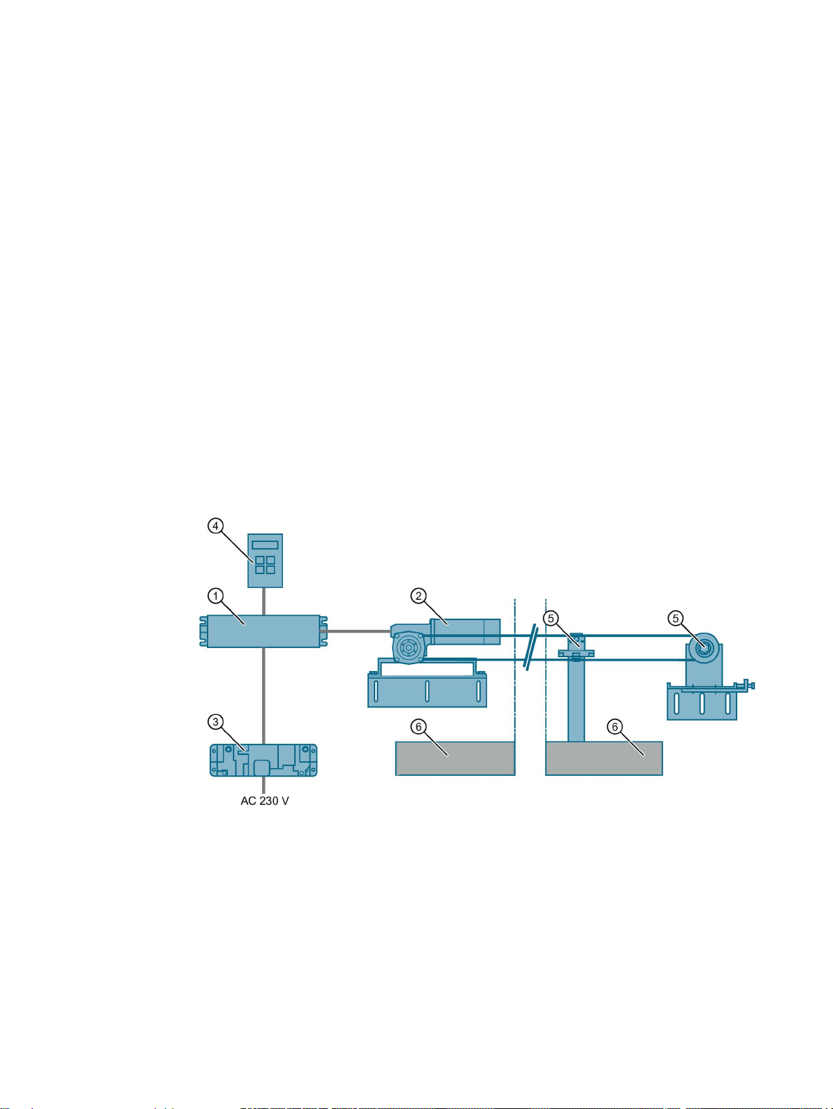
SIDOOR
Overview of the product family
①
④
Software Kit)
②
Geared motor
⑤
Accessories
③
Power supply
⑥
Sliding door
Door control system is the general term for a controller of an access system.
The SIDOOR product family is primarily intended for operating sliding doors. Different
versions of SIDOOR controllers enable both horizontal and vertical doors to be operated.
Door control systems are characterized by the fact that there are always two defined states:
namely for the open and closed positions of the door. The door is always controlled between
these two positions in accordance with the guidelines of the respective application.
In a defined learn run initiated by "one-button operation", the door system independently
determines the values for the door width, the dynamic door weight and the drive direction of
the geared motor, and stores these data in a non-volatile memory.
Controller
Optional additional unit (e.g. SIDOOR Service Tool, SIDOOR
Image 3-1 System setup
AT40, ATD400V, ATD400K, ATD4xxW, ATD400S, ATE250S, ATD400T
System Manual, 06/2016, A2B00096162-AN
17
Page 18

Product family
Technologies
DC technology
EC technology
DC technology
EC technology
Controllers
SIDOOR ATD400V ✓ —
SIDOOR ATD400K ✓ —
SIDOOR ATD400W ✓ —
SIDOOR ATD4xxW ✓ —
SIDOOR ATD400S ✓ —
SIDOOR ATE250S — ✓
SIDOOR ATD400T ✓ —
Geared motors
SIDOOR M2 ✓ —
SIDOOR M3 ✓ —
SIDOOR MDG180 ✓ —
DIN EN 45545-2
SIDOOR MEG250 — ✓
SIDOOR M4 ✓ —
SIDOOR MDG400 NMS
✓
—
SIDOOR MDG400 ✓ —
SIDOOR M5 ✓ —
Two different technologies are used in SIDOOR door control systems:
●
DC systems are two-phase driven, and have internal commutating brushes.
●
EC systems are three-phase driven, and are electronically commutated.
SIDOOR controllers and SIDOOR motors use the technologies as shown below:
Table 3- 1 Overview of technologies used
SIDOOR AT40 ✓ —
SIDOOR MDG180
AT40, ATD400V, ATD400K, ATD4xxW, ATD400S, ATE250S, ATD400T
✓ —
18 System Manual, 06/2016, A2B00096162-AN
Page 19

Product family
3.1
Products
3.1.1
Controllers
Versions
Controller
Article No.
Description
Elevators
Industrial applications
3.1 Products
Controllers are electronic controllers connected to the power supply via an external power
supply unit (SIDOOR NT40, SIDOOR Transformer). They are generally connected to the
higher-level controller via digital or fieldbus interfaces, and can be configured via a user
interface.
The controllers are designed for different areas of application. The following table provides
an overview of the available controllers.
SIDOOR AT40 RELAY 6FB1111-0AT10-3AT2
SIDOOR AT40 CAN 6FB1111-1AT10-3AT3
SIDOOR ATD400V RELAY 6FB1111-1AT10-3VE2
SIDOOR ATD400K RELAY LB 6FB1141-1AT10-3KU2
SIDOOR ATD400K RELAY RC 6FB1141-1AT11-3KU2
SIDOOR ATD401W 6FB1141-1AT11-3WE2
• Controller for horizontal elevator doors, up to 600 kg door
weight
• Relay module
• Controller for horizontal elevator doors, up to 600 kg door
weight
• Serial interface to the higher-level controller (CAN mod-
ule)
• Controller for rising gate and rolling shutter doors in the
elevator field of application, up to 400 kg door weight
• Relay module
• Controller for cold room gates, up to 400 kg door weight
• 1 DI for light barriers (LB)
• Relay module
• Controller for cold room gates, up to 400 kg door weight
• 1 DI for reed contact (RC)
• Relay module
• Controller for machine tools, up to 600 kg door weight
• Relay module
AT40, ATD400V, ATD400K, ATD4xxW, ATD400S, ATE250S, ATD400T
System Manual, 06/2016, A2B00096162-AN
19
Page 20

Product family
Controller
Article No.
Description
Railways
Platform screen doors
Interior railway doors
3.1 Products
SIDOOR ATD410W 6FB1141-4AT10-3WE2
SIDOOR ATD420W 6FB1141-2AT10-3WE2
SIDOOR ATD430W 6FB1141-3AT10-3WE2
SIDOOR ATD400S 6FB1131-0BM10-3AT3
SIDOOR ATE250S 6FB1231-0BM10-0AT3
• Controller for machine tools, up to 600 kg door weight
• USS bus interface to the higher-level controller (USS
module)
• Controller for machine tools, up to 600 kg door weight
• PROFIBUS interface to the higher-level controller
(PROFIBUS module)
• Controller for machine tools, up to 600 kg door weight
• PROFINET interface to the higher-level controller
(PROFIBUS module)
• Controller for platform screen doors, up to 400 kg door
weight
• Serial interface to the higher-level controller via the
SIDOOR AT-EB expansion unit
• Controller for platform screen doors, up to 250 kg door
weight
• Serial interface to the higher-level controller via the
SIDOOR AT-EB expansion unit
SIDOOR ATD400T RELAY 6FB1121-0BM13-3AT2
• Controller for interior railway doors, up to 400 kg door
weight
• Relay module
AT40, ATD400V, ATD400K, ATD4xxW, ATD400S, ATE250S, ATD400T
20 System Manual, 06/2016, A2B00096162-AN
Page 21

Product family
3.1.2
Geared motors
Versions
Geared motor
Article No.
Description
3.1 Products
Geared motors form the maintenance-free drive unit in the door drive. The geared motors
feature DC motors with non-self-locking gearing and are speed-controlled. The set force and
speed limits are not exceeded.
The power is transmitted by a gear rack or chain. Toothed belts or chains pass over a
deflector pulley, and can be fitted with 2 clutch holders. This enables it to drive both singlesided and centrally-opening doors.
SIDOOR M2 L 6FB1103-0AT10-5MA0
SIDOOR M2 R 6FB1103-0AT11-5MA0
SIDOOR M3 L 6FB1103-0AT10-4MB0
SIDOOR M3 R 6FB1103-0AT11-4MB0
SIDOOR MDG180 L 6FB1103-0AT14-4MB0
SIDOOR MDG180 R 6FB1103-0AT13-4MB0
SIDOOR MDG180 L
DIN EN 45545-2
SIDOOR MDG180 R
DIN EN 45545-2
SIDOOR MEG250 L 6FB1233-0BM00-0MP0
SIDOOR MEG250 R 6FB1233-0BM01-0MP0
6FB1103-0AT16-4MB0
6FB1103-0AT15-4MB0
• Geared motor, pinion left, max. 120 kg door weight
• Cable length 1.5 m
• Geared motor, pinion right, max. 120 kg door weight
• Cable length 1.5 m
• Geared motor, pinion left, max. 180 kg door weight
• Cable length 1.5 m
• Geared motor, pinion right, max. 180 kg door weight
• Cable length 1.5 m
• Geared motor, pinion left, max. 180 kg door weight
• Without cable*
• Geared motor, pinion right, max. 180 kg door weight
• Without cable*
• Geared motor, pinion left, max. 180 kg door weight
• Cable length 1.5 m
• Geared motor, pinion right, max. 180 kg door weight
• Cable length 1.5 m
• Electronically commutated geared motor, pinion left, max.
250 kg door weight
• Cable length 1.5 m
• Electronically commutated geared motor, pinion right,
max. 250 kg door weight
• Cable length 1.5 m
AT40, ATD400V, ATD400K, ATD4xxW, ATD400S, ATE250S, ATD400T
System Manual, 06/2016, A2B00096162-AN
21
Page 22

Product family
Geared motor
Article No.
Description
3.1 Products
SIDOOR M4 L 6FB1103-0AT10-3MC0
SIDOOR M4 R 6FB1103-0AT11-3MC0
SIDOOR MDG400 L 6FB1103-0AT14-3MC0
SIDOOR MDG400 R 6FB1103-0AT13-3MC0
SIDOOR M5 L 6FB1103-0AT10-3MD0
SIDOOR M5 R 6FB1103-0AT11-3MD0
SIDOOR MDG400 NMS L 6FB1103-0AT14-3MC1
SIDOOR MDG400 NMS R 6FB1103-0AT13-3MC1
* Cable can be ordered: See Section Accessories (Page 23)
• Geared motor, pinion left, max. 400 kg door weight
• Cable length 1.5 m
• Geared motor, pinion right, max. 400 kg door weight
• Cable length 1.5 m
• Geared motor, pinion left, max. 400 kg door weight
• Without cable*
• Geared motor, pinion right, max. 400 kg door weight
• Without cable*
• Geared motor, pinion left, max. 600 kg door weight
• Cable length 1.5 m
• Geared motor, pinon right, max. 600 kg door weight
• Cable length 1.5 m
• Geared motor, without pinion, max. 400 kg door weight
• Without cable*
• Geared motor, without pinion, max. 400 kg door weight
• Without cable*
AT40, ATD400V, ATD400K, ATD4xxW, ATD400S, ATE250S, ATD400T
22 System Manual, 06/2016, A2B00096162-AN
Page 23

Product family
3.1.3
Accessories
Accessories
Article No.
Description
motor is mounted
SIDOOR deflector pulley
6FB1104-0AT04-0AS0
Deflector pulley for deflecting the SIDOOR toothed belt
3.1 Products
SIDOOR rubber-metal antivibration mount
SIDOOR mounting bracket 6FB1104-0AT01-0AS0 Mounting bracket for mounting the SIDOOR rubber-metal
SIDOOR deflector unit 6FB1104-0AT03-0AS0
SIDOOR door clutch holder 6FB1104-0AT01-0CP0
SIDOOR toothed belt 6FB1104-0AT01-0AB0
6FB1104-0AT01-0AD0
6FB1104-0AT02-0AD0
6FB1104-0AT02-0AS0
6FB1104-0AT02-0CP0
6FB1104-0AT02-0AB0
6FB1104-0AT03-0AB0
6FB1104-0AT04-0AB0
• Rubber-metal anti-vibration mount for quiet operation of
the door drive system
• Recommended for mounting SIDOOR M4 R / L, MDG400
R / L, M5 R / L and MDG400 NMS R / L geared motors
• Rubber-metal anti-vibration mount for quiet operation of
the door drive system
• Recommended for mounting SIDOOR M2 R / L, M3 R / L,
MDG180 R / L, MDG180 R / L DIN EN 45545-2 and
MEG250 R / L geared motors
anti-vibration mount on which, in turn, a SIDOOR geared
• Mounting bracket with tensioning device for deflector
pulley
• For mounting the SIDOOR deflector unit and for tension-
ing the SIDOOR toothed belt
• Deflector unit with deflector pulley
• For deflecting the SIDOOR toothed belt in the same
height and depth, aligned with motor drive pinion
• Door clutch holder for 12 mm-wide toothed belt
• For attaching both ends of the toothed belt, and for con-
necting the respective door panel to the toothed belt
• Door clutch holder for 14 mm wide toothed belt
• For attaching both ends of the toothed belt, and for con-
necting the respective door panel to the toothed belt
• Single-toothed STS
• Super Torque toothed belt
• Length 4 m, width 12 mm.
• Single-toothed STS
• Super Torque toothed belt
• Length 45 m, width 12 mm.
• Single-toothed STS
• Super Torque toothed belt
• Length 4 m, width 14 mm.
• Single-toothed STS
• Super Torque toothed belt
• Length 55 m, width 14 mm.
AT40, ATD400V, ATD400K, ATD4xxW, ATD400S, ATE250S, ATD400T
System Manual, 06/2016, A2B00096162-AN
23
Page 24

Product family
Accessories
Article No.
Description
3.1 Products
SIDOOR
CABLE-RS485-MM-2m
SIDOOR
CABLE-RS485-MM-5m
SIDOOR
CABLE-RS485-MM-10m
SIDOOR CABLE AT-EB USB 6FB1124-0BM03-0CB0
SIDOOR CABLE-MDG-0.5m 6FB1104-0AT00-0CB5
SIDOOR CABLE-MDG-1.5m 6FB1104-0AT01-0CB5
SIDOOR CABLE-MDG-5m 6FB1104-0AT05-0CB0
SIDOOR CABLE-MDG-7m 6FB1104-0AT07-0CB0
SIDOOR CABLE-MDG-10m 6FB1104-0AT10-0CB0
SIDOOR CABLE-MDG-15m 6FB1104-0AT15-0CB0
6FB1124-0BM00-0CB0
6FB1124-0BM01-0CB0
6FB1124-0BM02-0CB0
• Cable from the SIDOOR AT-EB expansion unit to the
SIDOOR ATD400S
(Can also be used to connect the SIDOOR AT-EB expansion unit to the SIDOOR ATE250S)
• Cable length 2 m
• Cable from the SIDOOR AT-EB expansion unit to the
SIDOOR ATD400S
(Can also be used to connect the SIDOOR AT-EB to the
SIDOOR ATE250S)
• Cable length 5 m
• Cable from the SIDOOR AT-EB expansion unit to the
SIDOOR ATD400S
(Can also be used to connect the SIDOOR AT-EB expansion unit to the SIDOOR ATE250S)
• Cable length 10 m
• Programming cable to connect the USB adapter of the
SIDOOR Software Kit to the AT-EB
• Cable length 2 m
• Cable for connecting SIDOOR MDG180 R / L, MDG400 R
/ L / MDG400 NMS geared motors to SIDOOR ATD4xxW
controllers
• Cable length 0.5 m
• Cable for connecting SIDOOR MDG180 R / L, MDG400 R
/ L / MDG400 NMS geared motors to SIDOOR ATD4xxW
controllers
• Cable length 1.5 m
• Cable for connecting SIDOOR MDG180 R / L, MDG400 R
/ L / MDG400 NMS geared motors to SIDOOR ATD4xxW
controllers
• Cable length 5 m
• Cable for connecting SIDOOR MDG180 R / L, MDG400 R
/ L / MDG400 NMS geared motors to SIDOOR ATD4xxW
controllers
• Cable length 7 m
• Cable for connecting SIDOOR MDG180 R / L, MDG400 R
/ L / MDG400 NMS geared motors to SIDOOR ATD4xxW
controllers
• Cable length 10 m
• Cable for connecting SIDOOR MDG180 R / L, MDG400 R
/ L / MDG400 NMS geared motors to SIDOOR ATD4xxW
controllers
• Cable length 15 m
AT40, ATD400V, ATD400K, ATD4xxW, ATD400S, ATE250S, ATD400T
24 System Manual, 06/2016, A2B00096162-AN
Page 25

Product family
Accessories
Article No.
Description
controller
cable
higher-level SIMATIC controller
controllers
3.1 Products
SIDOOR CABLE-MDG-20m 6FB1104-0AT20-0CB0
PROFIBUS FC bus connector
RS 485
PROFIBUS FC Standard Cable
GP
IE FC RJ45 plug 180 4X2 6GK1901-1BB11-2AB0 Plug connector with axial cable outlet (180°) for connecting
IE FC TP Standard Cable GP 6XV1878-2A Cable for connecting the SIDOOR ATD430W controller to the
DIN rail holder 6FB1144-0AT00-3AS0 DIN rail holder with fixing screws for SIDOOR ATD4xxW
6GK1500-0FC10 Bus connector with axial cable outlet (180°, 20m) for connect-
6XV1830-0EH10 PROFIBUS cable for connecting SIDOOR ATD410W and
• Cable for connecting SIDOOR MDG180 R / L, MDG400 R
/ L / MDG400 NMS geared motors to SIDOOR ATD4xxW
controllers
• Cable length 20 m
ing SIDOOR ATD410W and SIDOOR ATD420W controllers
to the USS / PROFIBUS bus cable
SIDOOR ATD420W controllers to the higher-level SIMATIC
the SIDOOR ATD430W controller to the PROFINET bus
You will find more accessories in the Industry Mall (http://www.siemens.com/siplus/mall)
AT40, ATD400V, ATD400K, ATD4xxW, ATD400S, ATE250S, ATD400T
System Manual, 06/2016, A2B00096162-AN
25
Page 26

Product family
3.1.4
Power supply
Device selection
Power supply
Article No.
Description
SIDOOR NT40
6FB1112-0AT20-3PS0
SIDOOR Transformer
6FB1112-0AT20-2TR0
DC voltage supply (Page 276)
-
3.1 Products
SIDOOR power supplies connect the controllers to the respective application-specific power
supply.
Power supply for controllers without an integrated power
supply unit.
AT40, ATD400V, ATD400K, ATD4xxW, ATD400S, ATE250S, ATD400T
26 System Manual, 06/2016, A2B00096162-AN
Page 27
Product family
3.1.5
Optional additional units
Selection of additional units
Additional unit
Article No.
Description
2.
control systems via the proprietary RS 485 interface.
data and the current firmware version.
3.1 Products
Additional units meet a range of customer requirements in order to ensure the universal
implementation and maintenance of the system.
The additional units are easy to connect to a deenergized controller via the interfaces
provided – and are available for use as soon as the power supply is connected.
SIDOOR EMC FILTER 6FB1104-0AT20-0AT0 A line filter must be installed in the DC power supply to the
SIDOOR ATD400T RELAY controller to comply with the EMC
requirements for emitted interference set out in EN 50121-3-
SIDOOR AT-EB expansion unit
(with FW1.10)
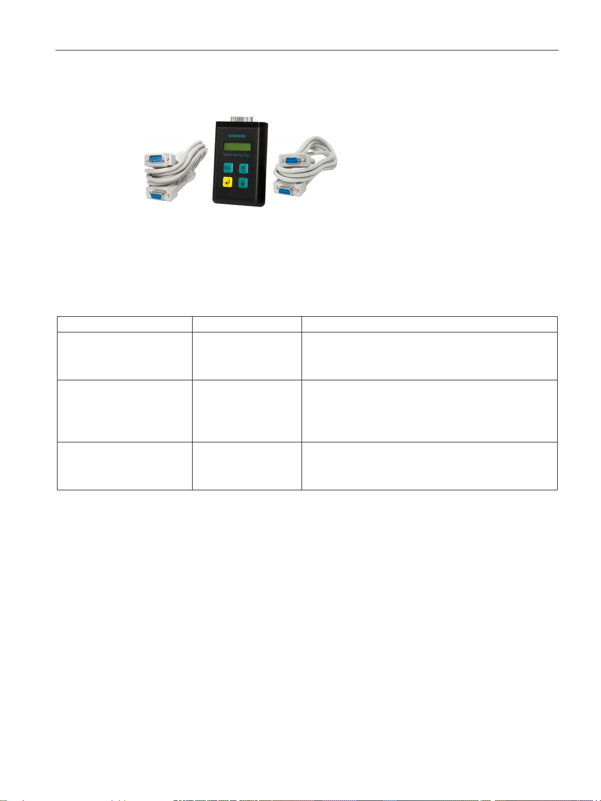
SIDOOR Service Tool 6FB1105-0AT01-6ST0 The SIDOOR Service Tool may be used to input door com-
6FB1135-2BM10-0CP0 The SIDOOR AT-EB expansion unit enables SIDOOR con-
trollers to be connected via a PROFIBUS DP interface, and
makes additional input and output signals available.
The SIDOOR AT-EB expansion unit controls up to two door
mands, to change drive parameters and to read the learnt
parameters, door states, input and output signals, service
AT40, ATD400V, ATD400K, ATD4xxW, ATD400S, ATE250S, ATD400T
System Manual, 06/2016, A2B00096162-AN
27
Page 28

Product family
3.1.6
Software
Selection
Software
Article No.
Description
3.1 Products
The optional SIDOOR Software Kit facilitates user-friendly operation and detailed diagnostics
via a PC.
SIDOOR Software Kit 6FB1105-0AT01-6SW0 The package includes the following components:
• Installation CD (Software Kit)
– Sidoor User Software
– Siemens HCS12 Firmware Loader
– Sidoor USB to UART Bridge driver
– License provisions
– SIDOOR Software Kit Operating Instructions
• 1 x USB adapter
• 1 x USB connecting cable
• 1x D-SUB connecting cable (9-pin, plug/socket)
• 1x D-SUB connecting cable (9-pin, socket/socket)
The contents of the SIDOOR Software Kit installation CD are also available as an Installation
package (http://support.automation.siemens.com/WW/view/en/92418945) from Industry
Online Support.
You can find more information about the SIDOOR Software Kit in the SIDOOR Software Kit
Operating Instructions (http://support.automation.siemens.com/WW/view/en/92711247).
AT40, ATD400V, ATD400K, ATD4xxW, ATD400S, ATE250S, ATD400T
28 System Manual, 06/2016, A2B00096162-AN
Page 29

4
4.1
Elevators
SIDOOR AT40
SIDOOR ATD400V
SIDOOR door drives are drives for doors and gates in various areas of application. The
controllers are optimally configured for their areas of application.
The following controllers are offered for elevator applications:
●
The comfort SIDOOR AT40 elevator door drive is an "intelligent" door drive with which
cabin and shaft doors can be opened and closed at adjustable speeds and accelerations.
●
The SIDOOR ATD400V hoisting and rolling shutter drive for elevators is an "intelligent"
door drive for the operation of vertical door systems on elevators.
AT40, ATD400V, ATD400K, ATD4xxW, ATD400S, ATE250S, ATD400T
System Manual, 06/2016, A2B00096162-AN
29
Page 30

Areas of application
4.2
Industrial applications
Industrial applications
SIDOOR ATD400K
SIDOOR ATD4xxW
SIDOOR ATD401W
SIDOOR ATD410W
USS bus
SIDOOR ATD420W
PROFIBUS DP
SIDOOR ATD430W
PROFINET IO
4.2 Industrial applications
We offer the following controllers for industrial applications:
●
The SIDOOR ATD400K RELAY LB and SIDOOR ATD400K RELAY RC industrial door
drives offer the optimal drive solutions for cold room gates weighing up to 400 kg. The
ATD400K RELAY LB model enables the connection of light barriers with "LB" logic, and
the ATD400K RELAY RC model enables the direct connection of a cord-operated switch
to open the gate.
Both drives meet the requirements of EN ISO 13849-1:2008 with regard to safety of
machinery and EN 12453:2000, section 5.2 with regard to safety in use of power
operated doors.
●
ATD4xxW machine tool door drives are "intelligent" door drives that can be used to
operate protective doors on machine tools. The safe functions - force limitation, energy
limitation and end position detection - fulfill the requirements according to
DIN EN ISO 13849-1:2008 for Category 2 and Performance Level d. The drives are
suitable for power-operated guards according to EN 953:1997+A1:2009 Section 5.2.5.2
"Actuating forces".
The SIDOOR ATD4xxW door controller enables connection to diverse fieldbus systems.
This makes integration into the industrial//Simatic environment possible. PROFINET IO,
PROFIBUS DP and USS are currently specified as fieldbuses. The PROFIBUS "variablespeed drives" profile is generally used as the higher-level device profile.
–
The "offline" relay variant can be used for simple automation tasks. As there is no
possibility of interfacing to a bus, it provides a limited scope of functions.
–
The controller is interfaced to a
You can find more detailed information about the USS protocol online at Industry
Online Support (http://support.automation.siemens.com/WW/view/de/24178253/0/en).
–
The
(AT-PB). This is an intelligent module that comes with its own firmware.
interface is realized by means of a modular PROFIBUS module
by means of a modular USS module.
–
The
(AT-PN). This is an intelligent module that comes with its own firmware.
AT40, ATD400V, ATD400K, ATD4xxW, ATD400S, ATE250S, ATD400T
30 System Manual, 06/2016, A2B00096162-AN
interface is realized by means of a modular PROFINET module
Page 31

Areas of application
4.3
Railways
Platform screen doors
SIDOOR ATD400S
SIDOOR ATE250S
Interior railway doors
SIDOOR ATD400T
4.3 Railways
The contents and structure of the user data transferred by the fieldbus systems
correspond to the PROFIBUS "variable speed drives" profile. Use of this profile is also the
basis for integration of the controller in the industrial environment. Both communicative
integration via a fieldbus system and safety-related aspects play an important role here.
SIDOOR ATD4xxW machine tool door drives enable connection of door closed/opened
position sensors (DCOPS), simple light barriers, pressure-sensitive edges as well as type
2 light arrays in compliance with IEC 61496 (ESPE - electrosensitive protective
equipment).
The SIDOOR ATD410W, SIDOOR ATD420W and SIDOOR ATD430W machine tool door
drives are characterized by their many functions, including "AssistedDrive" (motorassisted sliding of the door) and "ImpulseDrive" (automatic door movement initiated by
applying light force).
We offer the following controllers for railway applications:
●
–
The SIDOOR ATD400S platform screen door drive is an "intelligent" door drive system
which enables platform screen doors to be opened and closed at adjustable speeds
and accelerations.
It is not suitable for stand-alone operation. External commands are only accepted via
the serial interface. The SIDOOR ATD400S platform screen door drive must always
be operated in conjunction with the AT-EB expansion unit.
The ATD400S platform screen door drive can drive doors with a total door panel
weight of up to 400 kg.
–
The SIDOOR ATE250S platform screen door drive is an "intelligent" door drive which
drives platform screen doors.
It is not suitable for stand-alone operation. External commands are only accepted via
the serial interface. It has no control inputs (digital input signals). The SIDOOR
ATE250S platform screen door drive must therefore always be operated in conjunction
with a SIDOOR AT-EB.
The ATD250S platform screen door drive can drive doors with a total door panel
weight of up to 250 kg.
The SIDOOR ATD250S platform screen door drive uses EC technology. See Section
Product family (Page 17).
●
–
The SIDOOR ATD400T interior railway door drive is an "intelligent" door drive which
enables gangway doors to be opened and closed at adjustable speeds and
accelerations.
AT40, ATD400V, ATD400K, ATD4xxW, ATD400S, ATE250S, ATD400T
System Manual, 06/2016, A2B00096162-AN
31
Page 32

5
SIDOOR …
AT40
ATD400V
ATD400K
ATD4xxW
ATD400S
ATE250S
ATD400T
Geared motors
SIDOOR M2
✓ — — — ✓ — —
SIDOOR M3
✓ — ✓ ✓ ✓ — ✓
SIDOOR MDG180
— — — ✓ — — —
DIN EN 45545-2
SIDOOR MEG250
— — — — — ✓ —
SIDOOR M4
✓ ✓ ✓ ✓ ✓ — ✓*
SIDOOR MDG400
— — — ✓ — — —
SIDOOR M5
✓ — — ✓ — — —
Power supply
SIDOOR NT40
✓ ✓ — ✓ ✓ — —
SIDOOR Transformer
✓ — ✓ ✓ ✓ ✓ —
(Page 276)
Additional units
SIDOOR EMC FILTER
— — — — — — ✓
expansion unit
SIDOOR Software Kit
✓ ✓ ✓ ✓ ✓ ✓ ✓
SIDOOR Service Tool
✓ ✓ ✓ ✓ ✓ ✓ ✓
The following table shows which products you can combine with which controllers.
Table 5- 1 Overview of product combinations
SIDOOR MDG180
SIDOOR MDG400 NMS — — — ✓ — — —
DC voltage supply
SIDOOR AT-EB
— — — — — — ✓
— — — ✓ — — ✓
— — — — ✓ ✓ —
* Please observe the note entitled "SIDOOR ATD400T relay (6FB1121-0BM13-3AT2) –
supplementary technical specifications" in Section Technical specifications (Page 223).
AT40, ATD400V, ATD400K, ATD4xxW, ATD400S, ATE250S, ATD400T
32 System Manual, 06/2016, A2B00096162-AN
Page 33

6
6.1
Description
Overview
SIDOOR AT40 / ATD400V
①
Connecting terminals
②
Relay module / CAN module
③
Service buttons / Minimal editor
④
Terminal module
SIDOOR ATD400K / ATD400S / ATD400T
①
Connecting terminals
②
(not with ATD400S)
③
Service buttons / Minimal editor
④
Terminal module
Relay module / USS module / PROFIBUS module
AT40, ATD400V, ATD400K, ATD4xxW, ATD400S, ATE250S, ATD400T
System Manual, 06/2016, A2B00096162-AN
33
Page 34

Controllers
SIDOOR ATD4xxW
①
Connecting terminals
②
Relay module/USS module/PROFIBUS module/PROFINET module
③
Service buttons/Minimal editor
④
Terminal module
SIDOOR ATE250S
①
Connecting terminals
②
Terminal module
6.1 Description
AT40, ATD400V, ATD400K, ATD4xxW, ATD400S, ATE250S, ATD400T
34 System Manual, 06/2016, A2B00096162-AN
Page 35

Controllers
6.2
Drive functions
6.2.1
Overview
Overview of drive functions
SIDOOR
AT40
ATD400V
ATD400K
ATD401W
ATD410W/
ATD420W/
ATD430W
ATD400S
ATE250S
ATD400T
LB
RC
Light barrier (Page 39)
✓1)
✓1)
✓ — —
✓2) — —
—
Motion detector (Page 41)
— — — — — — — — ✓
higher)
Type 2 ESPE (Page 44)
— — — — ✓3)
✓3) — —
—
higher)
Gate interlocking (Page 47)
— — — ✓ — — — — —
Door locked (Page 48)
— — — — — — — — ✓
Nudge (Page 49)
✓ ✓ — — — — — — —
er)
(Page 51)
Stopping (Page 49)
✓ ✓ ✓ ✓ ✓ ✓ ✓ ✓ ✓
(Page 52)
higher)
6.2 Drive functions
This Section describes the complete range of drive functions of SIDOOR controllers. The
following table provides an overview of the SIDOOR controllers and their individual drive
functions.
Different drive functions have been implemented in the controllers according to their areas of
application.
DCPS (Door Closed Position
Sensor) (Page 41)
DCOPS (door closed/opened
position sensor) (Page 42)
Pressure-sensitive edge (SR)
(Page 46)
Force and energy profiles
(NDG mode) (Page 50)
Slow driving curve profile
Automatically delayed motion
Cord-operated switch
(Page 53)
DOOR CLOSE (command
given via digital inputs)
(Page 54)
✓1) ✓1) — — — — — — —
— — — — ✓
— — — — ✓3) ✓3)
— — — — ✓
— — — — — ✓ — — —
— — — — — — ✓ ✓ ✓
— — ✓ ✓ — — — — —
✓ ✓ ✓ ✓ ✓ ✓4)
1) 3)
✓
(V1.03
and high-
2) 3)
(V1.01 and
(V1.01 and
✓
(V1.01 and
higher)
(V1.01 and
— — —
— — —
— — —
— — ✓
AT40, ATD400V, ATD400K, ATD4xxW, ATD400S, ATE250S, ATD400T
System Manual, 06/2016, A2B00096162-AN
35
Page 36

Controllers
SIDOOR
AT40
ATD400V
ATD400K
ATD401W
ATD410W/
ATD420W/
ATD430W
ATD400S
ATE250S
ATD400T
LB
RC
higher)
higher)
(Page 57)
Overload protection (Page 57)
✓ ✓ ✓ ✓ ✓ ✓ ✓ ✓ ✓
ing (Page 58)
(Page 59)
ImpulseDrive (Page 65)
— — — — — ✓ — — —
(Page 66)
ImpulseStop (Page 67)
— — — — — ✓ — — —
(Page 68)
AssistedDrive (Page 69)
— — — — — ✓ — — —
er ON) (Page 71)
higher)
(Page 73)
er)
(Page 75)
(Page 76)
(Page 77)
(Page 81)
Push to open (Page 82)
— — — — — — — — ✓
Pull to close (Page 82)
— — — — — — — — ✓
6.2 Drive functions
DOOR OPEN (command
given via digital inputs)
(Page 55)
Partial opening (Page 56) — — — — ✓ ✓
Restart after power failure
Vandalism protection/continuous door monitor-
Obstruction detection
Automatic ImpulseDrive
Automatic ImpulseStop
Automatic AssistedDrive
(Page 70)
Initial run/reference run (Pow-
✓ ✓ ✓ ✓ ✓ ✓4)
(V1.01 and
(V1.01 and
✓ ✓ ✓ ✓ ✓ ✓ ✓ ✓ ✓
✓ ✓ ✓ ✓ ✓ ✓ ✓ ✓ ✓
✓ ✓ ✓ ✓ ✓ ✓ ✓ ✓ ✓
— — — — — ✓ — — —
— — — — — ✓ — — —
— — — — — ✓ — — —
— — — — — ✓ — — —
— — ✓
— — —
Positioning mode (Page 72) — — — — — ✓
Belt break monitoring
Emergency power mode
(Page 74)
Friction compensation
Oscillation protection
Automatic energy limitation
External closing force
AT40, ATD400V, ATD400K, ATD4xxW, ATD400S, ATE250S, ATD400T
36 System Manual, 06/2016, A2B00096162-AN
— — —
(V1.01 and
—6) —6) —6) —6) ✓ ✓ —6) ✓ ✓
✓ ✓ ✓ ✓ —
(V1.03
and high-
— — — — ✓ ✓ — — —
— ✓ ✓ ✓ ✓ ✓ ✓ ✓ ✓
✓ ✓ ✓ ✓ ✓ ✓ ✓ ✓ ✓
✓ ✓ ✓ ✓ — — ✓7) ✓7) ✓
✓ ✓ — —
Page 37

Controllers
SIDOOR
AT40
ATD400V
ATD400K
ATD401W
ATD410W/
ATD420W/
ATD430W
ATD400S
ATE250S
ATD400T
LB
RC
Emergency release (Page 82)
✓ ✓ ✓ ✓ ✓ ✓ ✓ ✓ ✓
Learn run (Page 83)
✓ ✓ ✓ ✓ ✓ ✓ ✓ ✓ ✓
V1.05)
V1.05)
higher)
higher)
Drive orders (Page 94)
— — — — ✓ ✓ — — —
higher)
er)
higher)
Diagnostics
Terminal module (Page 116)
✓ ✓ ✓ ✓ ✓ ✓ ✓ ✓ ✓
editor (Page 110))
(Page 292)
6.2 Drive functions
Force limit for learn run
(Page 85)
Output transmission
(Page 86)
Free function blocks
(FBLOCK) (Page 87)
Auto-Hotspot — — — — — ✓
Two-hand operation — — — — — ✓
Emergency stop — — — — ✓
Fail-safe digital control — — — — — ✓
— — — — ✓
(as of
V1.05)
— — — — ✓
(as of
— — — — — ✓
(V1.03
and high-
✓
(as of
V1.05)
✓
(as of
(V1.01 and
(V1.01 and
(V1.01 and
✓
(V1.01 and
higher)
(V1.01 and
— — —
— — —
— — —
— — —
— — —
— — —
— — —
7-segment display (see Section Service buttons / Minimal
SIDOOR Service Tool
AT40, ATD400V, ATD400K, ATD4xxW, ATD400S, ATE250S, ATD400T
System Manual, 06/2016, A2B00096162-AN
✓ ✓ ✓ ✓ ✓ ✓ ✓ — ✓
✓ ✓ ✓ ✓ ✓ ✓ ✓5) ✓5) ✓
37
Page 38

Controllers
SIDOOR
AT40
ATD400V
ATD400K
ATD401W
ATD410W/
ATD420W/
ATD430W
ATD400S
ATE250S
ATD400T
LB
RC
Update possible
✓ ✓ ✓ ✓ ✓ ✓ ✓ ✓ ✓
1)
2)
3)
4)
5)
6)
cm). A belt break error is not displayed; the controller instead switches
7)
tion of function)
Drive function parameter assignment
ATD4xxW (firmware version 1.03 or higher)
6.2 Drive functions
SIDOOR Software Kit
✓ ✓ ✓ ✓ ✓ ✓ ✓5) ✓5) ✓
(Page 28)
Light barrier and DCPS/DCOPS (ATD401W) cannot be implemented simultaneously.
Light barrier and DCOPS can be implemented simultaneously by connecting to a fieldbus system.
DCOPS, type 2 ESPE or pressure-sensitive edge cannot be implemented simultaneously.
Evaluated by PLC.
The connection to the SIDOOR AT-EB expansion unit must be severed.
Monitoring of the travel distance (door width + 10
to Init mode and an initial move must be executed.
External closing force is not provided for the customer side, however it can be installed. (See the notes in the descrip-
The respective parameters for the drive functions are fixed for the SIDOOR AT40, ATD400V,
ATD400K, ATD401W, ATD400S, ATE250S and ATD400T controllers and cannot be
changed.
The drive functions listed above can be assigned parameters, calibrated and configured on
SIDOOR ATD410W, ATD420W and SIDOOR ATD430W controllers. This is mainly done
using the higher-level controller (parameter channel). Refer to the corresponding function
descriptions for details of the parameters associated with the drive functions listed. You can
find more detailed information about the parameters in Section Parameter assignment
(ATD4xxW) (Page 170).
AT40, ATD400V, ATD400K, ATD4xxW, ATD400S, ATE250S, ATD400T
38 System Manual, 06/2016, A2B00096162-AN
The input signal wiring can be switched between two fixed configurations (see Digital input
signals (Page 131)).
Page 39

Controllers
6.2.2
Light barrier
Description of function
Exception:
Connection and parameter assignment
SIDOOR AT40 / ATD400V / ATD400K (RELAY LB)
Note
The light barrier and
implemented simultaneously.
SIDOOR ATD410W/ATD420W/ATD430W
Note
The light barrier signal is evaluated in the low
(= not interrup
6.2 Drive functions
The input for the light barrier signal has the same function as the DOOR OPEN command.
If the door is open less than 1 cm, the light barrier signal is ignored. If no power is
supplied at the light barrier input, this is interpreted as an interruption of the light barrier. The
door cannot then close.
If the light barrier signal is interrupted while the DOOR CLOSE command is active, the door
is moved in the OPEN direction. An interruption of the light barrier signal while the DOOR
CLOSE command is inactive does not change the state.
The light barrier signal can be connected via "Input 1" (X6). See also Section Digital input
signals (Page 131). The connected signal must be activated via the SIDOOR Service Tool
Main menu > General setup > Special parameters > Input 1
(
DCPS (Door Closed Position Sensor) (Page 41) functions cannot be
The sensor signal must be generated by the PLC as part of the process image. See Table 675 DCMD expansion bits (Page 207).
).
The status of the sequential control must be considered when using the LB signal. The
process data (including the LB signal) are only valid in the status "S4: Z_ operation" (see
Image 6-33 Sequential control state graph (Page 216)). The LB signal is evaluated in the
low-active state, but is not tested during the sensor function test.
When not in operating status "S4: Z_ operation" (see Image 6-33 Sequential control state
graph (Page 216)), the sensor signals are automatically assigned their resting signal value
so that they have no effect on the system status.
The travel range within which the controller reacts to the light barrier signal can be restricted
by parameter p1210. See Calibration and function parameters (Page 175).
You can find more detailed information on the light barrier in Section Overview (Page 159).
AT40, ATD400V, ATD400K, ATD4xxW, ATD400S, ATE250S, ATD400T
System Manual, 06/2016, A2B00096162-AN
-active state and must therefore be assigned 1
ted).
39
Page 40

Controllers
Signals
Signal
Description
Light barrier is not interrupted and the door closes when the DOOR
CLOSE command is present
* The response of SIDOOR ATD4xxW controllers also depends on the particular system mode. See
the table below.
Mode
Response
Learn run mode
Learn run is canceled and the drive is deenergized.
stopped
active "Close" drive order.
Reverses
In positioning mode, the drive is stopped via a ramp down.
stopped
active "Close" drive order.
6.2 Drive functions
1 (voltage applied)
0 (voltage not applied) Light barrier is interrupted and the door opens when the DOOR
CLOSE command is present*
Table 6- 1 Response of SIDOOR ATD4xxW controllers to an interrupted light barrier
Initial mode The system is
Normal mode
order.
The system response to an obstruction detected while reversing
can be configured accordingly. The following drive order can be
defined with parameter p1211 (see Section Calibration and function parameters (Page 175)).
Special mode The system is
the system in conjunction with the active "Close" drive
via a ramp down in conjunction with the
via a ramp down in conjunction with the
AT40, ATD400V, ATD400K, ATD4xxW, ATD400S, ATE250S, ATD400T
40 System Manual, 06/2016, A2B00096162-AN
Page 41

Controllers
6.2.3
Motion detector
Description of function
Connection and parameter assignment
Signals
Signal
Description
1 (voltage applied)
Signal present at motion detector
6.2.4
DCPS (Door Closed Position Sensor)
Description of function
6.2 Drive functions
If a signal is active at the input of the connected motion detector, the door opens according
to the set driving curve as long as the command is active. If the door is opened less than
1 cm, the motion detector signal is ignored. The door reaches the OPEN position at creep
speed. After expiry of the hold-open time, the door can be closed by an explicit close
command. If the parameter "Hold-open time after motion detector" is set to 0 s, the door can
be closed immediately by an explicit close command. If the door is opened less than 1 cm,
the motion detector signal is ignored.
The motion detector signal is connected via "Input 1" (X6). See also Section Digital input
signals (Page 131).
The following wait time in the OPEN position can be parameterized separately from the
normal open time. The parameter assignment is set via the parameter "Hold-open time after
motion detector".
0 (voltage not applied) No signal present at motion detector
DCPS stands for Door Closed Position Sensor or DOOR CLOSED sensor. The Door Closed
Position Sensor is not a special sensor, but an open or closed contact as far as the controller
is concerned. If the contact is closed, the door is in the CLOSED position. The user is
responsible for the design of the contact.
The DCPS enables the door to travel in normal operation immediately after the line voltage is
switched on without an initialization run. This requires the door to be in the CLOSED position
when the power is switched on. This enables the controller to be completely switched off if
the elevator is not going to be used for a lengthy period, for example during the night.
If the contact remains closed although the door has left its CLOSED position, the controller
switches to initial operation after 10 cm, and continues the movement at initial speed. The
door does not resume moving at normal speed until after it has traveled to both end
positions.
AT40, ATD400V, ATD400K, ATD4xxW, ATD400S, ATE250S, ATD400T
System Manual, 06/2016, A2B00096162-AN
41
Page 42

Controllers
Connection and parameter assignment
Note
The light barrier and DCPS functions cannot be implemented simultaneously.
Signals
Signal
Description
1 (voltage applied)
Door is in the CLOSED position
0 (voltage not applied)
Door is not in the CLOSED position
6.2.5
DCOPS (door closed/opened position sensor)
Description of function
Example sequence when using DCOPS
6.2 Drive functions
The DCPS signal can be connected via "Input 1" of the terminal X6. See also Section Digital
input signals (Page 131). The connected signal must be activated via the SIDOOR Service
Main menu > General setup > Special parameters > Input 1
Tool (
).
"DCOPS" stands for door closed/opened position sensor. A door closed/opened position
sensor can consist of two end position sensors (closed/open).
The DCOPS enables the door to travel immediately after the line voltage is switched on
without an initialization run in normal operation.
When the DCOPS signal is active in initial mode, the controller switches directly to normal
mode with a corresponding "Open" or "Close" drive order when an obstruction (end stop) is
detected. To prevent the erroneous detection of a blocking obstruction as an end stop, the
DCOPS signal must not be activated until 1 to 2 cm before the respective end stop.
1. Power ON
2. Controller is in the initial mode. No fault present. The system is in any position along the
travel path.
3. An "Open" or "Close" door command is present.
4. The system opens or closes.
5. The DCOPS signal is activated as from 2 cm before the respective end stop.
6. The system reaches the end stop and detects it as an "obstruction".
7. The system switches to the normal mode and assumes the applicable "open" or "closed"
status.
AT40, ATD400V, ATD400K, ATD4xxW, ATD400S, ATE250S, ATD400T
42 System Manual, 06/2016, A2B00096162-AN
Page 43

Controllers
Connection and parameter assignment
Note
The type
simultaneously.
SIDOOR ATD410W/ATD420W/ATD430W
Note
•
Image
•
•
6.2 Drive functions
The DCOPS signal can be connected to SIDOOR ATD4xxW controllers via "Input 1" of the
terminal X6. See also Section Digital input signals (Page 131).
The connected signal must be activated via the SIDOOR Service Tool (
General setup > Special parameters > Input 1
).
Main menu >
2 ESPE, pressure-sensitive edge and DCOPS functions cannot be implemented
The DCOPS signal can be sent as shown in Image 6-26 Sensor signals (Page 159), via the
process image (see Table 6-75 DCMD expansion bits (Page 207)) and/or via the local
sensor input ("Input 1" via p4600 - see Table 6-38 Other parameters (Page 172)).
The status of the sequential control must be considered when using the DCOPS signal
(process image). The process data is only valid in the "S4: Z_ operation" state (see
6-33 Sequential control state graph (Page 216)).
The light barrier and DCOPS functions can be implemented simultaneously by
connecting to a fieldbus system (process image).
The DCOPS, type 2 ESPE or pressure-sensitive edge functions cannot be implemented
simultaneously as sensor functions at input 1.
You can find more detailed information on DCOPS in Section Overview (Page 159).
AT40, ATD400V, ATD400K, ATD4xxW, ATD400S, ATE250S, ATD400T
System Manual, 06/2016, A2B00096162-AN
43
Page 44

Controllers
6.2.6
Type 2 ESPE
Function description
Connection and parameter assignment
Note
The DCOPS, type
simultaneously as sensor functions at input
6.2 Drive functions
A light array / light curtain is the part of the electro-sensitive protective equipment (ESPE)
that is connected to the machine controller and assumes a defined state when the sensing
device is triggered during intended use.
A type 2 ESPE can be connected to SIDOOR ATD4xxW controllers via "Input 1" of the
terminal X6.
If the SIDOOR controller's sensor logic is configured for ESPE, the "TestOUT" function test
signal is output automatically at the terminal X100.1. See Section Sensor function test
(Page 162).
The sensor type of the sensor connected to "Input 1" of terminal X6 can be configured as
follows:
● Parameter p4600
● Service menu:
The travel range within which the controller reacts to the OSSD signal can be restricted by
parameter p1210 (see Section Calibration and function parameters (Page 175)).
You will find a circuit diagram and detailed information about the connection of a
type 2 ESPE in Section Type 2 ESPE (Page 160).
MAIN MENU > General setup > Special parameters > Function Input 1
2 ESPE or pressure-sensitive edge functions cannot be implemented
1.
AT40, ATD400V, ATD400K, ATD4xxW, ATD400S, ATE250S, ATD400T
44 System Manual, 06/2016, A2B00096162-AN
Page 45

Controllers
Signals
Signal
Description
1 (voltage applied)
Light curtain is not interrupted.
* The response of SIDOOR ATD4xxW controllers also depends on the particular system mode. See
the table below.
Mode
Response
Learn run mode
Learn run is canceled and the drive is deenergized.
stopped
"Close" drive order.
Reverses
In positioning mode, the drive is stopped via a ramp down.
stopped
"Close" drive order.
6.2 Drive functions
0 (voltage not applied) Light curtain is interrupted*.
Table 6- 2 Response of SIDOOR ATD4xxW controllers to an active light curtain signal
Initial mode The system is
Normal mode
The system response to an obstruction detected while reversing can be
configured accordingly. The following drive order can be defined with
parameter p1211 (see Section Calibration and function parameters
(Page 175)).
Special mode The system is
the system in conjunction with the active "Close" drive order.
via a ramp down in conjunction with the active
via a ramp down in conjunction with the active
AT40, ATD400V, ATD400K, ATD4xxW, ATD400S, ATE250S, ATD400T
System Manual, 06/2016, A2B00096162-AN
45
Page 46

Controllers
6.2.7
Pressure-sensitive edge (SR)
Function description
Connection and parameter assignment
Note
The DCOPS, type
simultaneously as sensor functions at input 1.
6.2 Drive functions
The pressure-sensitive edge is connected to the machine control and assumes a defined
state if the sensor device is addressed during proper operation.
The output signal switching device of the pressure-sensitive edge is connected to "Input 1" of
the terminal X6.
If the SIDOOR controller's sensor logic is configured for a pressure-sensitive edge, the
"TestOUT" function test signal is output automatically at the terminal X100.1. See Section
Sensor function test (Page 162).
The sensor type of the sensor connected to "Input 1" of terminal X6 can be configured as
follows:
● Parameter p4600
● Service menu:
The travel range before the "Closed" position in which the controller responds to the
pressure-sensitive edge's signal can be restricted by parameter p1210 (see Section
Calibration and function parameters (Page 175)). The controller does not respond to the
pressure-sensitive edge's signal in the range of ± 2 cm before the "Open" position.
You will find a circuit diagram and detailed information about connection of a pressuresensitive edge in Section Pressure-sensitive edge (SR) (Page 161).
MAIN MENU > General setup > Special parameters > Function Input 1
2 ESPE or pressure-sensitive edge functions cannot be implemented
AT40, ATD400V, ATD400K, ATD4xxW, ATD400S, ATE250S, ATD400T
46 System Manual, 06/2016, A2B00096162-AN
Page 47

Controllers
Signals
Signal
Meaning
1 (high)
Pressure-sensitive edge is not interrupted and is fault-free.
* The response of SIDOOR ATD4xxW controllers also depends on the particular system mode. See
the table below.
Mode
Response
Learn run mode
Learn run is canceled and the drive is deenergized.
stopped
deenergized
junction with the active drive order.
20 cm
stopped
deenergized
stopped
deenergized
down.
Special mode
No response
6.2.8
Gate interlocking
Description of function
Signals
Signal
Description
1 (voltage applied)
Gate interlocking is active
0 (voltage not applied)
Gate interlocking is not active
6.2 Drive functions
0 (low) Pressure-sensitive edge is interrupted or defective*.
Table 6- 3 Response of SIDOOR ATD4xxW controllers to an active pressure-sensitive edge signal
Initial mode The system is
Normal mode The system reverses by
If the gate interlocking is active, the controller does not accept any control commands.
and then
The drive is
during reversing.
In positioning mode, the drive is
and then
via a ramp down in con-
in conjunction with the active drive order.
if an obstruction is detected
and
via a ramp
AT40, ATD400V, ATD400K, ATD4xxW, ATD400S, ATE250S, ATD400T
System Manual, 06/2016, A2B00096162-AN
47
Page 48

Controllers
6.2.9
Door locked
Description of function
Connection
Signals
Signal
Description
1 (voltage applied)
Door interlocking is active
6.2 Drive functions
If the "Door locked" command is active, the door control system responds as follows:
● The door drive is torque-free.
● The incoming commands "DOOR OPEN" and "Motion detector" are not evaluated by the
controller.
● The hold-open time is cancelled.
● The keyboard lighting is deactivated.
After the "Door locked" command is revoked, the door system becomes active again after a
delay of 3 s. The door then moves in the CLOSE direction.
The "Door locked" function is connected to "Input 2" (X6). See also Section Digital input
signals (Page 131).
0 (voltage not applied) Door interlocking is not active
AT40, ATD400V, ATD400K, ATD4xxW, ATD400S, ATE250S, ATD400T
48 System Manual, 06/2016, A2B00096162-AN
Page 49

Controllers
6.2.10
Nudge
Description of function
Connection
Signals
Signal
Description
activated at the same time. The reversing unit is deactivated.
0 (voltage not applied)
The nudge command is not present.
6.2.11
Stopping
Function description
6.2 Drive functions
If a "Nudge" command is present, the reversing unit is deactivated. The input signals CLOSE
and NUDGE must be active so that the NUDGE operating state is only effective in the
closing direction. When an obstruction is detected, the torque is reduced after 1 s to the
motor's holding shut torque limit.
The "Nudge" function is connected to "Input 2" (X6). See also Section Digital input signals
(Page 131).
The function is only active in conjunction with the CLOSE input signal.
1 (voltage applied) The nudge command is present if the DOOR CLOSE command is
See Table 6-10 SIDOOR door drive shutdown/deceleration functions (limited system)
(Page 95).
AT40, ATD400V, ATD400K, ATD4xxW, ATD400S, ATE250S, ATD400T
System Manual, 06/2016, A2B00096162-AN
49
Page 50

Controllers
6.2.12
Force and energy profiles (NDG mode)
Parameter assignment
Normal operation
NDG operation
Force limiting
p3683 "LimForceCls"
p3684 "LimForceEndCls"
Energy limiting
p1202 "KinEnergyLimCls"
p1203 "KinEnergyLimOp"
Speed limiting (influenced by energy limiting)
p3668 "MaxSpdCls"
p3664 "MaxSpdOp"
Drive order for profile switching
Switching profiles
Drive response in NDG mode
6.2 Drive functions
SIDOOR ATD4xxW controllers support two individually parameterizable force and energy
profiles.
You can configure the following parameters equally via the parameter interface, the service
tool and the terminal.
Table 6- 4 Force and energy profile parameter overview
p3682 "LimForceOp" p3685 "LimForceNdg"
p1204 "KinEnergyLimNdg"
p3672 "NdgSpd"
To switch to NDG mode, the DCMD expansion bit "NDG" must be set (see Table 6-75
DCMD expansion bits (Page 207)). In combination with an applicable DCMD drive order (see
Table 6-74 DCMD signal (Page 206)), the drive travels with the NDG force and energy
profile.
The drive switches over to the NDG force and energy profile when the corresponding drive
order with expansion bit is active and the controller is in normal mode. If the NDG mode is
activated or deactivated during travel, the system automatically stops with the configured
braking ramp and continues moving with the applicable force and energy profile after having
stopped.
Independent values, which are not influenced by the force and energy profiles described
here, apply to force and energy limiting in the initial or learn run mode.
In NDG mode, all drive functions are supported without restriction.
AT40, ATD400V, ATD400K, ATD4xxW, ATD400S, ATE250S, ATD400T
50 System Manual, 06/2016, A2B00096162-AN
Page 51

Controllers
6.2.13
Slow driving curve profile
Parameter assignment
Normal profile
Slow profile
Energy limiting
p1203 "KinEnergyLimOp"
p1204 "KinEnergyLimNdg"
(influenced by energy limiting)
p3668 "MaxSpdCls"
p3664 "MaxSpdOp"
p3672 "NdgSpd"
Drive order for profile switching
Switching profiles
Drive response
6.2 Drive functions
SIDOOR ATD4xxW controllers support a parameterizable, decelerated speed profile (slow
profile), to which it is possible to switch over to flexibly.
You can configure the following parameters equally via the parameter interface, the service
tool and the terminal.
Table 6- 5 Force and energy profile parameter overview
p1202 "KinEnergyLimCls"
Speed limiting
p3667 "SlowIniSpdOp"
p3671 "SlowIniSpdCls"
To switch to the slow profile, the DCMD expansion bit "slow" (see Table 6-75 DCMD
expansion bits (Page 207)) must be set. In combination with an applicable DCMD drive order
(see Table 6-74 DCMD signal (Page 206)), the drive switches to the slow profile.
The drive switches over to the slow profile when the corresponding drive order with
expansion bit is active and the controller is in normal mode. The slow profile can be activated
or deactivated dynamically during travel. The system accelerates or brakes the drive
automatically to the slow profile's speed according to the configured ramps.
Independent values, which are not influenced by the speed parameters described here,
apply to the speed in the initial or learn run mode.
When the slow profile is active, all drive functions are supported without restriction.
AT40, ATD400V, ATD400K, ATD4xxW, ATD400S, ATE250S, ATD400T
System Manual, 06/2016, A2B00096162-AN
51
Page 52

Controllers
6.2.14
Automatically delayed motion
Description of function
SIDOOR ATD400T
SIDOOR ATD400S and SIDOOR ATE250S
Parameter assignment
SIDOOR ATD400T
SIDOOR ATD400S and SIDOOR ATE250S
6.2 Drive functions
If the "Open" / "Close" command is present, relay X13 is activated, and the door is not
opened / closed until the preset timer "Time delay before movement" expires.
If the "Open" command is present, relay X11 is activated, and the door is not opened until
the time delay of 250 ms expires.
The function can be activated with the SIDOOR Service Tool by setting a time for the
parameter "Time delay before movement". If the parameter "Time delay before movement" is
set to 0 ms, then the function is deactivated and the door is opened / closed without the
timer.
The delay time is a fixed preset and cannot be parameterized.
AT40, ATD400V, ATD400K, ATD4xxW, ATD400S, ATE250S, ATD400T
52 System Manual, 06/2016, A2B00096162-AN
Page 53

Controllers
6.2.15
Cord-operated switch
Description of function
Connection
Signals
Signal
Description
1 (voltage applied)
The cord-operated switch command is present and the door opens
closes
6.2 Drive functions
The cord-operated switch command has the same function as the GATE OPEN command.
However, it also offers the option of partial opening. "Opening width in percent" and "Holdopen time cord operated switch" can be set in the Special parameters menu. The cordoperated switch command remains present until a new input signal is activated or the "Holdopen time cord operated switch" expires.
The "Nudge" function is connected to "Input 2" (X6). See also Section Digital input signals
(Page 131).
0 (voltage not applied) The cord-operated switch command is not present and the door
AT40, ATD400V, ATD400K, ATD4xxW, ATD400S, ATE250S, ATD400T
System Manual, 06/2016, A2B00096162-AN
53
Page 54

Controllers
6.2.16
DOOR CLOSE (command given via digital inputs)
Description of function
Exception ATD400K
Note
If the commands DOOR CLOSE and DOOR OPEN are present simultaneously, the door
always
Exception SIDOOR ATD400S and SIDOOR ATE250S:
the highest priority over all other control commands.
SIDOOR ATD410W/ATD420W/ATD430W
Note
As an alternative, the signal can also be evaluated via the PLC (process image).
Connection
Signals
Signal
Description
1 (voltage applied)
The DOOR CLOSE command is present
0 (voltage not applied)
The DOOR CLOSE command is not present
6.2 Drive functions
The DOOR CLOSE command must remain present continuously in order to close the door.
After the door has closed, it is held in this position by the torque that can be adjusted by the
parameter "Continuous torque CLOSE" as long as the command remains present.
arrives.
See also Section Free function blocks (FBLOCK) (Page 87).
: The DOOR CLOSE command remains present until a new input signal
moves in the OPEN direction.
The DOOR CLOSE command has
The "DOOR CLOSE" function is connected to "Input 3" (X6). See also Section Digital input
signals (Page 131).
AT40, ATD400V, ATD400K, ATD4xxW, ATD400S, ATE250S, ATD400T
54 System Manual, 06/2016, A2B00096162-AN
Page 55

Controllers
6.2.17
DOOR OPEN (command given via digital inputs)
Description of function
Exceptions:
SIDOOR ATD400K:
SIDOOR ATD400S and SIDOOR ATE250S:
Note
If the commands DOOR CLOSE and DOOR
always moves in the OPEN direction.
SIDOOR ATD410W/ATD420W/ATD430W
Note
As an alternative, the signal can also be evaluated via the PLC (process image).
Connection
Signals
Signal
Description
1 (voltage applied)
The DOOR OPEN command is present
0 (voltage not applied)
The DOOR OPEN command is not present
6.2 Drive functions
The DOOR OPEN command opens the door according to the set driving curve as long as
the command is present. The door reaches the OPEN position at creep speed. Then, if the
DOOR OPEN command is present, the door is held open by the torque that can be adjusted
by the parameter "Continuous torque OPEN".
The DOOR OPEN command has priority over all other control commands.
●
command.
●
highest priority over all other control commands.
The DOOR OPEN command has no priority over any other control
The DOOR CLOSE command has the
OPEN are present simultaneously, the door
See also Section Free function blocks (FBLOCK) (Page 87).
The "DOOR OPEN" function is connected to "Input 3" (X6). See also Section Digital input
signals (Page 131).
AT40, ATD400V, ATD400K, ATD4xxW, ATD400S, ATE250S, ATD400T
System Manual, 06/2016, A2B00096162-AN
55
Page 56

Controllers
6.2.18
Partial opening
Description of function
Requirements for partial opening mode
Connection and parameter assignment
SIDOOR ATD401W
SIDOOR ATD410W/ATD420W/ATD430W
6.2 Drive functions
A second open position can be implemented using the "partial opening" drive function. A
"partial opening" describes an opening movement with a set curve profile up to the partial
opening position.
When partial opening is active, the learned or real door width is replaced with the
parameterized partial opening width. All drive functions are supported in partial opening
mode (e.g. curve profile, force and energy limiting, obstruction detection, etc.). Activating
positioning mode overwrites partial opening mode.
If the drive is in the area between the first and second open positions when partial opening
mode is activated, this is detected as an invalid area. In this area, the controller reduces the
drive's speed automatically. The normal curve profile becomes active again as soon as the
drive has moved out of the invalid area or has exited partial opening mode. The scenario
described is not to be evaluated as a fault or an invalid situation.
The continuous torque in the opening direction is not applied at the virtual end stop of the
second open position. The drive is stopped as long as the open command is present
(winding short-circuited "source voltage brake").
The drive can only switch to partial opening mode if the corresponding drive order with
expansion bit is active and the following conditions are met:
● The controller is in normal mode
● The drive is at a stop
Partial opening mode can only be terminated actively (reset of the DCMD expansion bit
"partial") at standstill, but is terminated automatically if the controller switches to initial or
learn run mode.
The partial opening width can be configured via the driving parameters or the terminal
module (
The "Partial opening" function is connected to "Input 2" of terminal X6. See also Section
Digital input signals (Page 131).
The partial open width is defined via the parameter p1206. See Section Calibration and
function parameters (Page 175).
Main menu > General setup > Special parameters > Partly open width
).
AT40, ATD400V, ATD400K, ATD4xxW, ATD400S, ATE250S, ATD400T
56 System Manual, 06/2016, A2B00096162-AN
Page 57

Controllers
6.2.19
Restart after power failure
Description of function
SIDOOR ATD400T - Error response during the initialization run
SIDOOR ATD410W/ATD420W/ATD430W
6.2.20
Overload protection
Description of function
SIDOOR AT40
SIDOOR ATD4xxW
6.2 Drive functions
After a power failure, the controller has to redetermine the end positions of the door travel.
To do this, the door travels at reduced speed (initial speed) until the controller has detected
the OPEN and CLOSED end positions. The door then resumes traveling at normal speed.
The door travels at normal speed immediately if the DCPS (see Section DCPS (Door Closed
Position Sensor) (Page 41)) or DCOPS (see Section DCOPS (door closed/opened position
sensor) (Page 42)) is installed. In this case, the door must be in the CLOSED position for the
restart.
During the initialization run, five attempts are made to travel through the stored door width.
An error case is signaled by error "P.", and the door remains stationary in the presumed
"closed" position.
After Power ON, the sequential control system is in the "S1: Switching On Inhibited" mode
(see Image 6-33 Sequential control state graph (Page 216)).
If the drive motor placed under a high load with frequent DOOR OPEN and DOOR CLOSE
commands in quick succession, the hold-open time is automatically lengthened. The next
closing movement is delayed even if a DOOR CLOSE command is present, the 7-segment
display (H401)/digital display (H1) shows "4". This function prevents thermal overloading of
the motor.
Reversing the direction of rotation or restarting the controller several times puts a
disproportionate strain on the drive motor.
The controller switches to motor protection mode for 30 seconds and does not accept any
door commands. This state is signaled by a "4" on the 7-segment display (H401)/the digital
display (H1).
This function prevents thermal overloading of the motor.
The fault "4" is generated if the drive is moved continuously in one direction for more than
65 s. This is intended to prevent thermal overloading of the motor. This can only arise in the
event of extremely high levels of system friction, at maximum door width.
AT40, ATD400V, ATD400K, ATD4xxW, ATD400S, ATE250S, ATD400T
System Manual, 06/2016, A2B00096162-AN
57
Page 58

Controllers
6.2.21
Vandalism protection/continuous door monitoring
Description of function
SIDOOR ATD410W/ATD420W/ATD430W
Parameter assignment
SIDOOR ATD410W/ATD420W/ATD430W
6.2 Drive functions
The vandalism protection/continuous door monitoring function offers protection against
undesired external system motion. If the motor is deenergized, the motor speed is monitored
by the controller.
If the maximum speed of 250 mm/s is exceeded, the controller actively decelerates the
motor to 50 mm/s, and then switches the drive back to "deenergize".
If the maximum configurable speed (p1200) is exceeded, the controller actively decelerates
the motor to 50 mm/s, and then switches the drive back to "deenergize".
The "Continuous door monitoring" function is pre-installed and activated, and can be
deactivated if necessary with parameter p1200. This is done by setting the value of
parameter p1200 to "0". See Table 6-40 Calibration and function parameters (Page 175).
AT40, ATD400V, ATD400K, ATD4xxW, ATD400S, ATE250S, ATD400T
58 System Manual, 06/2016, A2B00096162-AN
Page 59

Controllers
6.2.22
Obstruction detection
6.2.22.1
Obstruction detection CLOSE
Description of function
SIDOOR ATD400S / ATE250S
SIDOOR ATD400T
SIDOOR ATD4xxW
6.2 Drive functions
If the door is obstructed in the CLOSE direction with a DOOR CLOSE command present, the
door stops and reverses direction. After reaching the OPEN position, the door closes again
at normal speed to within about 2 cm of the obstruction. It then travels at reduced speed
(initial speed) against the obstruction before reversing again. This function is repeated
continuously, as long as the obstruction remains. Once the obstruction has been cleared, the
door travels at reduced speed to approximately 2 cm past the stored position of the
obstruction, and then continues the rest of the way at normal closing speed.
If the door is obstructed in the CLOSE direction with a DOOR CLOSE command present, the
door presses against the obstruction with the set closing force. If the obstruction remains
present for more than one second, then the ATD400S controller reduces the motor current to
the rated current of the motor, and the force is reduced correspondingly. The ensuing force
is never greater than 150 N. This function is repeated continuously as long as the obstruction
remains present. Once the obstruction has been cleared, the door travels at reduced speed
to approximately 2 cm past the stored position of the obstruction, and then continues the rest
of the way at normal closing speed.
If the door is obstructed in the CLOSE direction with a DOOR CLOSE command present, the
door stops and reverses direction. After reaching the OPEN position, the door closes again
at normal speed to within about 2 cm of the obstruction. It then travels at reduced speed
(initial speed) against the obstruction before reversing again.
This function is repeated as many times as specified in the parameter "Number of
obstruction CLOSE retries before wait mode". During this time the obstruction is detected at
the same position ± 3 cm.
The door then remains stationary in this position. An OPEN signal cannot be accepted as an
external door command. A "completed" signal is then output on the keyboard lighting.
After the time specified by the parameter "Time delay in wait mode CLOSE" another attempt
is made to move in the CLOSE direction. This function is repeated continuously, as long as
the obstruction remains.
Once the obstruction has been cleared, the door travels at reduced speed to approximately
2 cm past the stored position of the obstruction, and then continues the rest of the way at
normal closing speed.
See Section SIDOOR ATD4xxW obstruction detection (Page 61).
AT40, ATD400V, ATD400K, ATD4xxW, ATD400S, ATE250S, ATD400T
System Manual, 06/2016, A2B00096162-AN
59
Page 60

Controllers
6.2.22.2
Obstruction detection OPEN
Description of function
Exceptions: SIDOOR ATD400S / ATE250S
SIDOOR ATD4xxW
6.2 Drive functions
The door stops if it is obstructed in the "OPEN" direction when the DOOR OPEN command
is present. After approximately 2 s, the door automatically tries to reach the OPEN position
again. This action is repeated a maximum of 3 times. The door then remains stationary in
this position. If the DOOR OPEN command is canceled, the close command given, and the
DOOR OPEN command is then repeated, the door travels at normal speed to within about
2 cm of the stored position of the obstruction, and then up to the obstruction at reduced
speed. The door drive stops at the obstruction, and the opening action is repeated another
3 times. If the obstruction has been removed beforehand, the door travels at reduced speed
to approximately 2 cm past the stored position of the obstruction, and then continues to the
OPEN position at normal speed.
If the door is obstructed in the OPEN direction with a DOOR OPEN command present, the
door presses against the obstruction with the set opening force. If the obstruction remains
present for more than one second, then the SIDOOR ATD400S controller reduces the motor
current to the rated current of the motor, and the force is reduced correspondingly. This
function is repeated continuously, as long as the obstruction remains.
Once the obstruction has been cleared, the door travels at reduced speed to approximately
2 cm past the stored position of the obstruction, and then continues the rest of the way at
normal closing speed.
See Section SIDOOR ATD4xxW obstruction detection (Page 61).
AT40, ATD400V, ATD400K, ATD4xxW, ATD400S, ATE250S, ATD400T
60 System Manual, 06/2016, A2B00096162-AN
Page 61

Controllers
6.2.22.3
SIDOOR ATD4xxW obstruction detection
Description of function
SIDOOR ATD401W (SIDOOR ATD4xxW factory default, firmware version 1.03 or higher)
SIDOOR ATD410W/ATD420W/ATD430W (up to firmware version 1.03)
in the opening direction
in the closing direction
Note
SIDOOR ATD4xxW obstruction detection (firmware version 1.03 or higher)
The behavior of the obstruction detection of ATD4xxW controllers corresponds to that of the
SIDOOR ATD401W controller.
The factory
controllers is parameterizable.
The factory
parameterizable.
6.2 Drive functions
If the controller detects an obstruction in the opening or closing direction with the aid of
obstruction detection, it reverses once by 20 cm, starts an attempt to retract and then
switches to wait mode. Slow obstruction approach, force obstruction detection and stop
obstruction detection are active.
● If the controller detects an obstruction
detection, three retries are initiated, each offset by 2 s.
● If the controller detects an obstruction
detection, it reverses by 20 cm and starts an attempt to retract. This operation is repeated
twice and is offset by 2 s in each case.
The controller then switches to wait mode. Slow obstruction approach, force obstruction
detection and stop obstruction detection are active in both cases.
by means of obstruction
by means of obstruction
-set obstruction behavior of SIDOOR ATD410W, ATD420W and ATD430W
-set obstruction behavior of the SIDOOR ATD401W controller is not
A detected obstruction is signaled by the DBLOCK signal (see Table 6-83 DBLOCK signal
(Page 211)).
The subsequent response to a detected obstruction depends on the user-defined parameter
assignment. The following properties can be configured separately for the opening and
closing directions:
● Obstruction detection
● Direct response
● Behavior following an obstruction
Basically, the same parameters are available for both drive directions. This means that either
the same or different obstruction behavior can be configured for each direction.
The obstruction detection is a dynamic system that responds as a function of both position
and time. The obstruction detection is dynamically activated or deactivated according to
these dependencies. You will find more detailed information in Section Expert configuration
(Page 64).
AT40, ATD400V, ATD400K, ATD4xxW, ATD400S, ATE250S, ATD400T
System Manual, 06/2016, A2B00096162-AN
61
Page 62

Controllers
Obstruction detection process
Force obstruction detection
Stop obstruction detection
Overcome obstruction
Example
Parameter assignment
6.2 Drive functions
The obstruction detection is based on two processes that are independent of the direction:
force obstruction detection and stop obstruction detection.
The following definitions are based on the speeds and are thus independent of the direction.
The obstruction detection systems assume that the system is actively being moved (drive
order).
●
The current speed is > 90 mm/s, and drops by more than 90 mm/s in comparison to the
maximum speed reached during the current movement.
If the system then moves for the set duration (p3854 and/or p3871) at the upper force
limitation, a force obstruction is detected in the current drive direction.
●
If the current speed is less than 10 mm/s for the set duration (p3853 and/or p3870), a
stop obstruction is detected in the current drive direction.
The overcome obstruction system can be used to overcome a blocking obstruction by
repeated pushing. The system remains active as long as the initial drive order is not actively
changed.
1. The drive order "close" is present.
2. The system closes.
3. An obstruction is detected before the end stop "closed" is reached.
4. The second of four retries is made.
5. The drive order "close" is overwritten by any other drive order.
6. The retry system is immediately exited.
7. The system responds according to the new drive order.
The number of retries to overcome the obstruction can be set in parameter p3860 or p3877.
If the number is set to "0", the overcome obstruction system is disabled in the corresponding
direction.
A variable waiting time can be configured before each retry (p3861 or p3878).
The type of drive control during this wait time can be "stop" or "deenergize" (p3862 or
p3879).
After the configured number of retries have been made, wait mode is activated (see the
following Section "Wait mode"). A following drive order can also be configured, which is
activated at the same time as the switch to wait mode (p3863 or p3880).
While the retry system is active, any external change to a drive order (see Table 6-74 DCMD
signal (Page 206)) immediately ends all open retry actions (including the cancelation of wait
mode).
AT40, ATD400V, ATD400K, ATD4xxW, ATD400S, ATE250S, ATD400T
62 System Manual, 06/2016, A2B00096162-AN
Page 63

Controllers
Reversing (Retraction attempt)
Parameter assignment
Note
A reverse due to a drive order being changed is part of the basic software, and is not
affected by the reversing on account of an obstruction described here (Open → Close, Close
→ Open).
Combination of retry and reverse
6.2 Drive functions
When an obstruction is detected, the obstruction reversing system can be used to initiate an
immediate full or partial reverse - a retraction attempt. This system is simply termed
"reverse". The system remains active as long as the initial drive order is not actively
changed. You can find an example of this in Section Overcome obstruction (Page 62).
The number of reversals (retraction attempts) can be defined in parameters p3864 and
p3881. If the number is set to "0", the obstruction reversing system is disabled in the
corresponding direction.
A variable wait time can be configured (p3865 and p3882) after each retraction attempt (on
reaching the corresponding reverse target position). The drive remains stopped during the
wait time.
The reversing distance or the type of reverse (full or partial reverse) can be configured to an
accuracy of ±2 cm in parameters p3866 and p3883.
If the system is obstructed while reversing, all still open reversing actions are immediately
ended, and wait mode is activated (see Wait mode (Page 64)). A following drive order can
also be configured in parameters p3867 and p3884, which is activated at the same time as
the switch to wait mode.
After the configured number of reversing operations/retraction attempts have been made,
wait mode is activated (see Wait mode (Page 64)). A following drive order can also be
configured, which is activated at the same time as the switch to wait mode (p3868 and
p3885).
While the obstruction reversing system is active, any change in an external drive order (see
Table 6-74 DCMD signal (Page 206)) immediately ends all open reversing actions (including
the cancelation of wait mode).
The reverse and retry systems can be combined. The combination is subject to the following
rules:
● A reverse is made after executing the configured number of retries. The action is
repeated for the number of configured reverses.
● Parameters p3863 and p3880 have no effect when reversing is activated.
● Wait mode becomes active after the last reverse.
● If the number of retries and reversing operations is set to "0", the "retry" following drive
order has a higher priority than the "reverse" drive order.
AT40, ATD400V, ATD400K, ATD4xxW, ATD400S, ATE250S, ATD400T
System Manual, 06/2016, A2B00096162-AN
63
Page 64

Controllers
Slow obstruction approach
Wait mode
Note
If the parameters p3860 and
DBLCWAIT becomes active immediately after an obstruction is detected.
Expert configuration
Parameter assignment
Function configuration
Lead times
Range restriction
before reaching
after leaving
before
after
6.2 Drive functions
The position of the last obstruction in the drive direction is automatically stored in the system.
The speed is automatically reduced to the corresponding creep speed (p3670 or p3666) on
approaching this position. The system calculates a braking ramp so that the reduced speed
is reached at the set distance (parameter p3855 or p3872) from the stored position of the
obstruction. If the obstruction can be overcome, the system adjusts the speed after the same
distance back to the "normal" driving curve.
Slow obstruction approach can be activated or deactivated for each drive direction in
parameter p3850.
Wait mode is activated according to the configurations of the overcome obstruction system
and the obstruction reversing system. If the system is in wait mode, this is ended any
external change to a drive order. Wait mode is signaled by the process data signal
"DBLCWAIT" (see "Table 6-84 DBLCWAIT signal (Page 211)").
The obstruction detection system has been designed so that it can be adapted to the widest
range of system environments, structures and properties. The following parameters are
mainly provided for such adaptations, and have to be changed for standard systems.
●
●
●
p3864, or p3877 and p3881 are set to "0", the signal
Stop and force obstruction detection can be deactivated for each drive direction in
parameter p3850 (bits 0 and 1, and 4 and 5 respectively). The counting of obstructions
can also be suppressed for each drive direction (bits 2 and 5).
After a drive order is changed or the direction of motion is reversed, the obstruction
detection is activated after a variable ON-delay time (p3852 and p3869).
Obstruction detection is suppressed in a variable range
the relevant end
stop (p3856 and p3873).
It is also suppressed
the relevant end stop (p3857 and p3874).
Force obstruction detection, in particular, is suppressed
and p3875). It is suppressed in a variable range
p3876).
AT40, ATD400V, ATD400K, ATD4xxW, ATD400S, ATE250S, ATD400T
64 System Manual, 06/2016, A2B00096162-AN
the creep distance (p3858
the last obstruction (p3859 and
Page 65

Controllers
6.2.23
ImpulseDrive
Description of function
Parameter assignment
Note
Configuring ImpulseDrive detection directly affects the au
automatic AssistedDrive and the automatic AssistedStop system.
Requirements for ImpulseDrive detection
Distance-based ImpulseDrive analysis
6.2 Drive functions
The ImpulseDrive analysis process detects and evaluates external impulses applied to the
door system (for example, slight force exerted on the door in the opening or closing
direction).
In conjunction with the automatic ImpulseDrive system (see Section Automatic ImpulseDrive
(Page 66)), a heavy door can be set in motion by applying a slight force to the door handle or
door frame.
When the process detects an external impulse, corresponding status information (see Table
6-87 IMPDRVIncr signal (Page 212) and Table 6-88 IMPDRVVelo signal (Page 212)) is
generated.
The ImpulseDrive detection properties can be individually parameterized to enable adaption
to different door systems.
The detection algorithm consists of a distance and a speed component. The sensitivity levels
of both components can be parameterized separately (p1221 and p1222). A parameterizable
lead time (p1220) is added to the detection algorithm to prevent problems caused by the
spring effects of sealing or rubber lips.
See Table 6-40 Calibration and function parameters (Page 175).
tomatic ImpulseDrive, the
● Parameters are matched to the target system
● Controller is not in learn run
● Drive command is "deenergize" ("DCMD := 0")
● No obstruction has been detected in the detected direction of motion
The analysis is based on the increments of the motor encoder in relation to an internal
reference value. This reference value is always specified when the door command is
changed to "deenergize" within the "S4: Z_operation" system state (see Image 6-33
Sequential control state graph (Page 216)) and the lead time (p1220) has expired.
The sensitivity level can be specified in parameter p1221. The higher it is, the higher the
number of increments counted before the signal IMPDRVInc changes to high (active).
AT40, ATD400V, ATD400K, ATD4xxW, ATD400S, ATE250S, ATD400T
System Manual, 06/2016, A2B00096162-AN
65
Page 66

Controllers
Speed-based ImpulseDrive analysis
6.2.24
Automatic ImpulseDrive
Function description
Note
The configuration of ImpulseDrive detection directly affects the automatic ImpulseDrive
system.
6.2 Drive functions
The analysis is based on the increments of the motor encoder or the actual speed derived
from it. The evaluation is only made in the "S4: Z_operation" system state (see Image 6-33
Sequential control state graph (Page 216)) after the door command has been changed to
"deenergize" and the lead time (p1220) has expired.
Both analyses use a sign to distinguish the directions.
The automatic ImpulseDrive system generates a drive order based on ImpulseDrive
detection.
If the ImpulseDrive analysis process detects an external impulse, the automatic
ImpulseDrive system generates a drive order with a normal drive profile. Both ImpulseDrive
detection output signals, IMPDRVVelo and IMPDRVIncr, are evaluated. If an enable
command is present, the automatic system initiates opening or closing with a normal drive
profile.
The automatic ImpulseDrive can only be used with an active enable. The enabling signal
(DCMD := 7) is an element of the DCMD signal (see Table 6-74 DCMD signal (Page 206)).
Image 6-1 Automatic ImpulseDrive system
AT40, ATD400V, ATD400K, ATD4xxW, ATD400S, ATE250S, ATD400T
66 System Manual, 06/2016, A2B00096162-AN
Page 67

Controllers
6.2.25
ImpulseStop
Function description
Parameter assignment
6.2 Drive functions
The ImpulseStop analysis process detects and analyzes external forces acting on the door
system/drive system.
In conjunction with the automatic ImpulseStop system (see Section Automatic ImpulseStop
(Page 68)), a door can be stopped with a light tug against the direction of travel.
The process signals when an external opposing force (force with an opposite direction vector
to that of the door movement) acts on the door or the drive. It is signaled by the ASStp signal
(see Table 6-90 ASStp signal (Page 213)).
The detection properties of ImpulseStop can be individually parameterized, thus enabling the
feature to be adapted to different door systems. The limit values for detecting an external
opposing force can be specified for each drive direction with the following parameters:
● p1240 in the opening direction
● p1241 in the closing direction
The parameters define a proportion of the learned reference value for each direction. This
proportion is added to the reference value, and thus forms the limit value for detecting
ImpulseStop.
AT40, ATD400V, ATD400K, ATD4xxW, ATD400S, ATE250S, ATD400T
System Manual, 06/2016, A2B00096162-AN
67
Page 68

Controllers
6.2.26
Automatic ImpulseStop
Function description
Note
Configuring ImpulseDrive analysis and detection
system.
Note
The automatic ImpulseStop is a dynamic function. It can be enabled and disabled during a
door movement.
6.2 Drive functions
The automatic ImpulseStop system is an expansion of the automatic ImpulseDrive system.
This means that all the properties, configurations and preconditions defined for it are also
applicable here.
The system can be activated by the "ImpulseStop" expansion bit (see Table 6-75 DCMD
expansion bits (Page 207)) in conjunction with automatic ImpulseDrive enabling (see Table
6-74 DCMD signal (Page 206)).
If the "ImpulseStop" expansion bit is active, the automatic ImpulseDrive system works in the
slow drive profile. The drive orders "slow open" and "slow close" are generated instead of
"open" and "close" respectively. The active drive order is canceled ("deenergized") as soon
as the ImpulseStop analysis/detection signals a corresponding opposing force (the rising
signal edge is decisive).
directly affects the automatic ImpulseStop
Image 6-2 Automatic ImpulseStop system
AT40, ATD400V, ATD400K, ATD4xxW, ATD400S, ATE250S, ATD400T
68 System Manual, 06/2016, A2B00096162-AN
Page 69

Controllers
6.2.27
AssistedDrive
Function description
Parameter assignment
Note
The config
system.
Prerequisites for AssistedDrive
Initial mode
Normal mode
Slow drive profile
6.2 Drive functions
AssistedDrive is an analysis process that detects and analyzes external forces acting on the
door or drive system.
In conjunction with the automatic AssistedDrive system (see Section Automatic
AssistedDrive (Page 70)), a door can be moved with motor assistance without the need for
buttons or sensors.
AssistedDrive signals (see Table 6-89 ASDRV signal (Page 213)) whenever an external
assisting force (force with the same direction vector as that of the door movement) acts on
the door or the drive.
The detection properties of AssistedDrive can be individually parameterized, thus enabling
the feature to be adapted to different door systems. The thresholds for the detection of
external opposing forces can be specified for each drive direction with the following
parameters:
● p1231 in the opening direction
● p1232 in the closing direction
The "slow" speed profile is adjusted with both of the following driving parameters:
● p3666 in the opening direction
● p3669 in the closing direction
See Table 6-37 Driving parameters (Page 171).
uration of AssistedDrive detection directly affects the automatic AssistedDrive
AssistedDrive detection is only active during the following internal system states:
●
●
●
(closing, closed, opening and open)
(closing, partial closure, closed, opening, partial opening and open)
(DCMD – expansion bit "slow", see Table 6-75 DCMD expansion bits
(Page 207))
If the system switches into one of the three system states, the signal ASDrv is always set to
active. The actual threshold analysis of the motor current starts after the parameterized
switch-off delay (p1230) and as soon as the value of the square of the difference between
the setpoint and actual speeds falls below 70 mm/s.
AT40, ATD400V, ATD400K, ATD4xxW, ATD400S, ATE250S, ATD400T
System Manual, 06/2016, A2B00096162-AN
69
Page 70

Controllers
Note
The falling edge of the ASDRV signal can only be reached when the difference between the
setpoint and actual speeds falls below the defined value. Therefore a speed and/
adjustment of the system may be required.
6.2.28
Automatic AssistedDrive
Function description
6.2 Drive functions
The result of the analysis is output by the signal state ASDrv. The falling signal edge
therefore indicates that the assisting force has become too low. Assisted mode can be
exited. This signal is independent of the drive direction.
or force
The automatic AssistedDrive system is composed of both the ImpulseDrive and
AssistedDrive detection systems.
On the one hand, ImpulseDrive is used to generate a corresponding drive order with a
normal drive profile. On the other hand, the drive order is canceled ("deenergized") with the
aid of AssistedDrive.
To do this, automatic AssistedDrive evaluates the edges of the IMPDRVIncr, IMPRDRVVelo
and ASDR signals.
The automatic AssistedDrive system can only be used with an active enable. The enabling
signal for the automatic AssistedDrive system (DCMD := 6) is an element of the DCMD
signal (see Table 6-74 DCMD signal (Page 206)). This ensures the unambiguity of the active
drive order at all times.
Image 6-3 Automatic AssistedDrive system
AT40, ATD400V, ATD400K, ATD4xxW, ATD400S, ATE250S, ATD400T
70 System Manual, 06/2016, A2B00096162-AN
Page 71

Controllers
Note
After the automatic AssistedDrive system has canceled a drive order on account of an
inadequate assisting force, ImpulseDrive detection becomes active again.
ImpulseDrive lead time (p1220) must be taken into account. It directly affects the signal
chain of the automatic AssistedDrive system.
Note
Configuring ImpulseDrive and AssistedDrive detection directly affects the automatic
AssistedDrive
6.2.29
Initial run/reference run (Power ON)
Description of function
speed
Force limitation
Using an end position sensor
6.2 Drive functions
However, the
system.
After Power ON, the controller is in initial mode. Initial mode is necessary because there is
no absolute value encoder. After Power ON, the controller must therefore verify the end
stops that have been previously learned (= reference run). As long as both end stops have
not been verified by reaching them, the drive only moves with a decelerated travel profile
(initial travel profile). Force limitation is active in accordance with the learned parameters
(friction compensation is active).
● The
●
After Power ON, the sequential control system is in the "S1:Z_switching on inhibited" state
(see Sequential control (Page 216)).
You can skip initial mode by connecting a DCOPS end position sensor (Door
Closed/Opened Position Sensor). Depending on the application, 1 end position sensor can
be used in the open or closed position or 2 end position sensors can be used in both end
positions. The responsibility for verification of the learned end positions is thus transferred to
the user (see Section DCOPS (door closed/opened position sensor) (Page 42)).
of the initial run is defined by the parameters p3667 and p3671.
during the initial run is defined by the parameters p3682 and p3683.
AT40, ATD400V, ATD400K, ATD4xxW, ATD400S, ATE250S, ATD400T
System Manual, 06/2016, A2B00096162-AN
71
Page 72

Controllers
6.2.30
Positioning mode
NOTICE
Obstruction detection
Activation
Sensors
Motor protection
6.2 Drive functions
Positioning mode serves to absolutely position the drive. The positioning system calculates a
travel profile for the optimum movement of the drive to the required target position on the
basis of the driving parameters and the current distance from the target position. Positioning
mode does not include any position control and operates with an accuracy of 1 cm. The
source voltage brake is activated once the target position has been reached. After the target
position has been reached, the door can be moved ±2 cm out of the target position before
the drive returns to the target position. The positioning system operates with hysteresis. The
drive responds dynamically (including reversing) to changes in the target position data while
keeping to the values parameterized for force and energy limiting.
The obstruction detection system (see Section Obstruction detection (Page 59)) is not
active in positioning mode.
Positioning mode can only be activated from normal mode and at standstill via the
"positioning" door command. It can be modified by the "NDG" and "slow" door command
extensions. The target position is transferred as the DESTPOS signal (see Table 6-77
DESTPOS signal (Page 207)) in technology control word 2 (TSW2) of the process image.
The target position is automatically limited to the learned door boundaries.
Sensor signals are evaluated in positioning mode. You will find the response of the
controller/drive to the applicable sensor signals in Section Type 2 ESPE (Page 44) or
Pressure-sensitive edge (SR) (Page 46).
To protect the motor, a monitoring function is active that switches off (deenergizes) the drive
if the specified target position cannot be reached, e.g. due to an obstruction.
AT40, ATD400V, ATD400K, ATD4xxW, ATD400S, ATE250S, ATD400T
72 System Manual, 06/2016, A2B00096162-AN
Page 73

Controllers
6.2.31
Belt break monitoring
Description of function
Mode
Controller
Distance
Initial operation
SIDOOR ATD4xxW
50 cm (p1201)
SIDOOR ATD400T
50 cm
Normal operation
SIDOOR ATD4xxW
50 cm (p1201)
SIDOOR ATE250S
10 cm
SIDOOR ATD400T
50 cm
Parameter assignment
SIDOOR ATD4xxW
6.2 Drive functions
The function detects a torn belt. The detection is active in normal mode and initial mode.
A torn belt is detected when the door movement exceeds the defined distance* (in the
opening or closing direction).
* The distance is defined as follows:
SIDOOR ATE250S 10 cm
Max. door width +
Learnt door width +
Belt break detection is suppressed if parameter p1201 is set to "0". In this case, there is no
fault or fault reaction on the part of the controller.
The status code "t" signals a torn belt. The controller changes to the "S6: Z_Fault" status
(see Image 6-33 Sequential control state graph (Page 216)).
If the parameter set of the controller is invalid, the maximum possible door width of 5 m is
used as the door width.
See Table 6-40 Calibration and function parameters (Page 175).
AT40, ATD400V, ATD400K, ATD4xxW, ATD400S, ATE250S, ATD400T
System Manual, 06/2016, A2B00096162-AN
73
Page 74

Controllers
6.2.32
Emergency power mode
Description of function
Parameter assignment
SIDOOR ATD410W/ATD420W/ATD430W
Signals
Signal
Meaning
1 (voltage applied)
Emergency power mode active
6.2 Drive functions
If the line voltage fails, the connected emergency power module sends a signal to the
controller. The speed-reduced driving curve profile (slow open und slow close) is
automatically used in emergency power mode. Emergency power mode cannot be exited
until the controller has reached the closed or open state in normal mode.
By way of the factory default, the "emergency power mode" function block is already linked
to Input 0 (terminal X5 – "Accumulator Mode").
Emergency power mode is mapped as a special function block and can be linked
dynamically as required. See Section Free function blocks (FBLOCK) (Page 87).
0 (voltage not applied) Emergency power mode not active
AT40, ATD400V, ATD400K, ATD4xxW, ATD400S, ATE250S, ATD400T
74 System Manual, 06/2016, A2B00096162-AN
Page 75

Controllers
6.2.33
Friction compensation
Description of function
Recording of measurement data
in the opening direction
in the closing direction
Calculations
Note
The friction force is not taken into account in the parameterized torques p3679, p3680
an
6.2 Drive functions
The friction force profile of the door system is recorded with the current measuring device of
the controller. The measurement data for both the opening and closing directions is recorded
during the learn run.
The recording of measurement data
because the door movement is not constant throughout the total range. The ranges are:
● Travel path ≤ 25 cm
– The measurement data in this range are recorded in the second opening movement
● Travel path > "End of weight determination"
– The measurement data in this range are recorded after the weight determination has
and after reaching the speed trigger level (learn run speed). As from this moment, the
door movement is almost constant. The measurement data are recorded every 2 cm,
the first measured value is recorded 2 cm after the trigger level position (transient
distance).
finished and the speed trigger level has been reached (learn run speed). As from this
moment, the door movement is almost constant. The measurement data are recorded
every 2 cm, the first measured value is recorded 2 cm after the trigger level position
(transient distance).
is divided into two subranges
The measurement data are recorded
movement within the learn run and after reaching the speed trigger level (learn run speed).
As from this moment, the door movement is almost constant. The measurement data are
recorded every 2 cm, the first measured value is recorded 2 cm after the trigger level
position (transient distance). The measured values are recorded until the system reaches the
"Cutter distance CLOSE" range (p3663).
1. The values "MEAN FRICTION FORCE OPEN/CLOSE [A]" and "STANDARD DEVIATION
OPEN/CLOSE [A]" in the "open" and "closed" positions are calculated on the basis of the
measurement data.
2. The values calculated in step 1 are converted to a force [N] with the aid of the motor
constants [N/A]
3. The force calculated in step 2 is added internally to the parameterized forces p3682,
p3683, p3684, and p3685
d p3681 (effective in the end stops) in order to avoid unnecessary heating of the motor.
throughout the entire closing
AT40, ATD400V, ATD400K, ATD4xxW, ATD400S, ATE250S, ATD400T
System Manual, 06/2016, A2B00096162-AN
75
Page 76

Controllers
Note
The corresponding internal force value, which is the result of the addition of the
parameterized force value and the calculated friction force, is limited
of the respective parameter.
6.2.34
Oscillation protection
End position "open"
End position "closed"
6.2 Drive functions
to the maximum value
The oscillation protection prevents permanent oscillation of the door at the end stop.
If the system is pressed out of the end position with the drive order "open" present, the
system detects that the "open" position has been left, and attempts to return to the end stop
with the set static opening force.
After reaching the end stop, the drive is energized with the set continuous torque.
The behavior described may be repeated five times (oscillation). After the fifth repetition, the
drive is energized for 30 s with the set continuous torque without any response to further
oscillations. After a protective period of 30 s, the system responds once again to
corresponding oscillations.
If the system is pressed out of the end position with the drive order "close" present, the
system detects that the "closed" position has been left, and attempts to return to the end
stop with the set static cutter force.
After reaching the end stop, the drive is energized with the set cutter press-on torque. After
2 s, the cutter press-on torque is limited to the set continuous torque.
The behavior described may be repeated five times (oscillation). After the fifth repetition, the
drive is energized for 30 s with the set continuous torque without any response to further
oscillations. After a protective period of 30 s, the system responds once again to
corresponding oscillations.
AT40, ATD400V, ATD400K, ATD4xxW, ATD400S, ATE250S, ATD400T
76 System Manual, 06/2016, A2B00096162-AN
Page 77

Controllers
6.2.35
Automatic energy limitation
Description of function
WARNING
Risk of injury due to moving mechanical parts
SIDOOR ATD4xxW
not
Force and energy profiles (ATD4xxW)
6.2 Drive functions
SIDOOR controllers have a system that automatically limits the kinetic energy in the closing
direction.
Independently of the maximum closing speed automatically determined during the learn
run, the kinetic energy of the door in the closing direction has to be checked by the
commissioning engineer after a learn run.
• According to EN 81, the kinetic energy of the door in the closing direction must not
exceed 10 joules while the reversing device is enabled.
• Without enabled reversing device, the kinetic energy of the door in the closing direction
must not exceed 4 joules according to EN 81 and each closing operation must be
signaled acoustically. The signal sound is not part of the SIDOOR system and must be
secured externally and made available by the operator.
The set maximum closing speed and the nudging speed must be reduced accordingly.
Check the final application-specific limit values and adjust the limit values accordingly.
SIDOOR ATD4xxW controllers include a system that automatically limits the kinetic energy
in the opening and closing directions.
The energy limitation values are specified in the parameters p1202 (in the closing direction)
and p1203 (in the opening direction). After a successfully completed learn run, the speed
values of driving parameters p3668 and p3664 are determined and overwritten according to
the determined weight and configured energy limitation.
The automatic energy limitation can be suppressed by setting the corresponding energy
limiting parameter to "0". Suppressed energy limiting means that the respective speed is
overwritten by the learn run.
See Section Force and energy profiles (NDG mode) (Page 50).
AT40, ATD400V, ATD400K, ATD4xxW, ATD400S, ATE250S, ATD400T
System Manual, 06/2016, A2B00096162-AN
77
Page 78

Controllers
Speed limit curve (in the closing direction*)
6.2 Drive functions
*SIDOOR ATD4xxW: Opening and closing directions
The speed limit curve is the characteristic that determines the maximum permissible door
speed (closing speed), v
the maximum kinetic energy of the door in the closing direction must not exceed 10 joules.
W
= 1/2 m ∙ v² = 10 J.
KIN
Example from the following speed limit curve:
, as a function of the total door panel weight. According to EN 81,
max
● Total door panel weight m = 180 kg => v
Image 6-4 Speed limit curve for WKIN=10J
= 0.33 m/s.
max
If the reversing device is switched off, the maximum kinetic energy must not exceed 4 joules.
W
= 1/2 m ∙ v² = 4 J.
KIN
AT40, ATD400V, ATD400K, ATD4xxW, ATD400S, ATE250S, ATD400T
78 System Manual, 06/2016, A2B00096162-AN
Page 79

Controllers
Adjustment ranges
6.2 Drive functions
Example from the following speed limit curve:
● Total door panel weight m = 180 kg => v
Image 6-5 Speed limit curve for WKIN=4J
= 0.21 m/s.
max
You will find the adjustment ranges in Section Profiles and adjustment ranges (Page 296).
AT40, ATD400V, ATD400K, ATD4xxW, ATD400S, ATE250S, ATD400T
System Manual, 06/2016, A2B00096162-AN
79
Page 80

Controllers
Maximum speeds
Maximum speeds [mm/s] depending on door weight and energy limiting
Door weight
[kg]
Energy [J]
4
10
25
50
75
100
50
400
632
1000
1414
1732
2000
100
283
447
707
1000
1225
1414
150
200
200
316
500
707
866
1000
250
179
283
447
632
775
894
300
163
258
408
577
707
816
350
151
239
378
535
655
756
400
141
224
354
500
612
707
450
133
211
333
471
577
667
500
126
200
316
447
548
632
550
121
191
302
426
522
603
600
115
183
289
408
500
577
Parameter assignment
SIDOOR ATD4xxW
6.2 Drive functions
The table below shows the maximum speeds depending on door weight and energy limiting:
Table 6- 6
The energy limitation values are specified in both of the following parameters:
231 365 577 816 1000 1155
● In closing direction: p1202
● In opening direction: p1203
Parameter assignment is possible via the driving parameters or the terminal module.
If one of the two energy limitation parameters is set to 0, the speed limitation is suppressed
according to the kinetic energy.
AT40, ATD400V, ATD400K, ATD4xxW, ATD400S, ATE250S, ATD400T
80 System Manual, 06/2016, A2B00096162-AN
Page 81

Controllers
6.2.36
External closing force
Description of function
WARNING
Risk of injury due to moving mechanical parts
SIDOOR ATD400S and SIDOOR ATE250S
SIDOOR ATD400T
Description
Permissible total door panel weight with a maximum spring force
of 80 N:
System friction of 10 to 70 N is allowed for
Inclination 0°
Inclination 5°
Inclination 10°
acceleration)
(a
max
= 1.3 m/s²)
(a
max
= 0.4 m/s²)
(a
max
= 0.3 m/s²)
acceleration)
(a
max
= 0.9 m/s²)
(a
max
= 0.9 m/s²)
(a
max
= 0.9 m/s²)
6.2 Drive functions
Closing mechanisms in the form of a counterweight or a spring are permissible for a
particular system.
You will find the permissible counterweights in Section Technical specifications (Page 223).
Make sure that with an additional external closing force the sum of external closing force
and force set in the controller does not exceed the maximum force limit of 150 N (according
to EN 81).
Check the final application-specific limit values and adjust the limit values accordingly.
An external closing force on the user side is not provided for in SIDOOR ATD400S and
SIDOOR ATE250S controllers. However, an external closing force (counterweight, spring)
can be installed.
This must be taken into account in the parameter assignment of the door control system.
Table 6- 7 Permissible total door panel weight for SIDOOR ATD400T with SIDOOR M3 / MDG180
DIN EN 45545-2 geared motor
Single-panel door system with
spring
(The spring force affects the
Single-panel door system without
spring
Twin-panel door system with
spring
(The spring force affects the
Twin-panel door system without
spring
180 kg
(a
= 1.3 m/s²)
max
180 kg
180 kg
(a
= 0.9 m/s²)
max
180 kg
140 kg
(a
= 0.3 m/s²)
max
180 kg
180 kg
(a
= 0.9 m/s²)
max
180 kg
80 kg
(a
= 0.3 m/s²)
max
120 kg
180 kg
(a
= 0.9 m/s²)
max
180 kg
The grade resistance on twin-panel doors compensates for the inclination.
AT40, ATD400V, ATD400K, ATD4xxW, ATD400S, ATE250S, ATD400T
System Manual, 06/2016, A2B00096162-AN
81
Page 82

Controllers
6.2.37
Push to open
Description of function
6.2.38
Pull to close
Description of function
6.2.39
Emergency release
Description of function
WARNING
An emergency release can only be actuated if the following conditions are met:
not
6.2 Drive functions
The controller automatically detects a DOOR OPEN command if a door is pulled manually in
the opening direction by more than 2 cm.
The controller automatically detects a DOOR CLOSE command if a door is pulled manually
by more than 2 cm in the closing direction.
• Neither a DOOR OPEN nor a DOOR CLOSE command is present,
• The service buttons are not pressed.
• The terminal module, SIDOOR Service Tool and SIDOOR User Software are
Quick setup or General setup menu items or one of their sub-menus.
• The door has come to a complete stop.
The door drive is only torque-free if these conditions are fulfilled. The force required to open
the door is less than 300 N in accordance with the requirement of EN 81.
in the
AT40, ATD400V, ATD400K, ATD4xxW, ATD400S, ATE250S, ATD400T
82 System Manual, 06/2016, A2B00096162-AN
Page 83

Controllers
6.2.40
Learn run
Description of function
Note
For the M4, MDG400, MDG400 NMS and M5 motors, the
must be checked prior to each learn run and adjusted if necessary.*
Types of learn run (via learn run button)
When the line voltage is applied
During operation
6.2 Drive functions
A learn run serves to determine and store the characteristics of a particular system.
* SIDOOR ATD4xxW
Two types of learn run can be made if the learn run button is pressed as follows:
●
If the learn run button is operated directly when the line voltage is applied, the connected
motor type is learned. All driving parameters and force and energy limiting parameters
are automatically reset to their factory defaults before the learn run is begun. The learn
run determines the door width, weight and friction. The speed in NDG mode and the
maximum closing and opening speeds are also limited as a function of the determined
weight and parameterized energy limiting. Friction compensation is also coordinated with
the determined door parameters.
output transmission (Page 86)
Application examples: initial commissioning or when commissioning a new motor type
●
If the learn run button is actuated during ongoing operation, a learn run is started to
determine the door's width, weight and friction. The speed in NDG mode and the
maximum closing and opening speeds are also limited as a function of the determined
weight and parameterized energy limiting. Friction compensation is also coordinated with
the determined door parameters. The driving parameters and force and energy limiting
parameters are retained.
Application examples: modifying the properties of the door system (door width or friction)
AT40, ATD400V, ATD400K, ATD4xxW, ATD400S, ATE250S, ATD400T
System Manual, 06/2016, A2B00096162-AN
83
Page 84

Controllers
Learning in new motors (ATD4xxW)
Note
If a learn run is started with a new mo
connected one, for safety reasons the energy limiting parameters (p1202, p1203 and p1204)
and internal friction compensation are reset for all driving parameters.
For the M4, MDG400. MDG400 NMS and M5 moto
be configured. For the M4, MDG400 and M5 motors, set the default value to 176 mm/rev.*
The learn run does not start when a value is set outside the permitted value range for the
output transmission (for example, de
Starting a learn run via the learn run button
Interrupting the learn run (SIDOOR ATD4xxW, ATE250S)
6.2 Drive functions
The learned motor type is stored in the controller and compared with the connected motor
when the controller is switched on. The controller's operating status display shows the status
code "5" if the learned motor type differs from the connected one. A new learn run (when the
line voltage is applied) or a special learn run is needed to learn in the new motor type.
SIDOOR ATD4xxW controllers enable learning of a new motor type by means of a special
learn run, which can be started as follows:
● DCMD "Start learn run" (see Table 6-74 DCMD signal (Page 206)) and DCMD "special"
expansion bit (see Table 6-75 DCMD expansion bits (Page 207))
● In the service terminal via
MAIN MENU > General setup > Start learn run with new motor
tor and if the learned motor type differs from the
fault value: 0).
* SIDOOR ATD4xxW
You can start a learn run via the learn run button (S401/S1*). Proceed as described in
Section Service buttons (Page 110).
* SIDOOR ATE250S
rs, the output transmission [mm/rev] must
Users can interrupt the learn run. The system signals an interrupted learn run through the
door fault status and by changing to a special mode. The operating status display shows the
warning "_". See Section Operating state display (Page 183).
The following actions interrupt an active learn run:
● Repeated operation of the learn run button (S401/S1*)
● Operating the OPEN or CLOSE service buttons (S402/S2* or S403/S3*)
● Door command change (except "deenergized") via the terminal, the service interface or
the fieldbus system**
● Interruption of the ESPE or the pressure-sensitive edge**
* SIDOOR ATE250S
** SIDOOR ATD4xxW
AT40, ATD400V, ATD400K, ATD4xxW, ATD400S, ATE250S, ATD400T
84 System Manual, 06/2016, A2B00096162-AN
Page 85

Controllers
Querying determined values
SIDOOR ATD4xxW
6.2.41
Force limit for learn run
Description of function
Note
The force only needs to be adjusted for smooth
door system has a door weight <100 kg and ma
Connection and parameter assignment
SIDOOR ATD410W / ATD420W / ATD430W
6.2 Drive functions
The values determined for the effective weight and the door width can be queried via the
terminal module.
SIDOOR ATD4xxW controllers also enable querying via the following parameters:
● Effective weight: r2101
● Door width: r2103
Force that is active during the learn run. The force limit is active in the closing and opening
direction.
The parameter depends on the existing output transmission. The force limit is set to the
maximum value by default.
The force limit can be configured via the terminal module (
Special parameters > Force limit for learn run
The force limit is set via the parameter p1242. See section Calibration and function
parameters (Page 175) for more on this.
-running door systems. A smooth-running
ximum frictional forces of <20N.
Main menu > General setup >
).
AT40, ATD400V, ATD400K, ATD4xxW, ATD400S, ATE250S, ATD400T
System Manual, 06/2016, A2B00096162-AN
85
Page 86

Controllers
6.2.42
Output transmission
Description of function
Door weight [kg]
200
X X X
n.r.
300
X
X
n.r.
n.r.
400
X
n.r.
n.r.
n.r.
n.r. not recommended
Note
For the M4, MDG400 and M5 motors, set default value to 176 mm/rev.
Note
The output tr
Note
The determined door width has to be checked after each learn run.
Note
Activation of the learn run via the bus interface
The learn run can only be started when an al
the door width should then be read back via the parameter r2103 and checked.
Connection and parameter assignment
SIDOOR ATD410W / ATD420W / ATD430W
6.2 Drive functions
For the M4, MDG400. MDG400 NMS and M5 motors, the output transmission must be
configured. The output transmission describes the transformation of rotational into
translational motion. Therefore: The distance [mm] that the door travels with one revolution
[rev] of the transmission output shaft. The output transmission can be adjusted within the
range 0...384 mm/rev. The permitted values are between 88...384 mm/rev. The default value
for a newly trained motor type is 0 mm/rev.
Output transmission
[mm/rev]
< 200 < 250 < 300 < 384
100 X X X X
ansmission should be checked before each learn run and adjusted if necessary.
The force limit can be configured via the terminal module (
Special parameters > Output transmission
lowable value has been entered. The value for
Main menu > General setup >
).
The output transmission is set via the parameter p4602. See section Calibration and function
parameters (Page 175) for more on this.
AT40, ATD400V, ATD400K, ATD4xxW, ATD400S, ATE250S, ATD400T
86 System Manual, 06/2016, A2B00096162-AN
Page 87

Controllers
6.2.43
Free function blocks (FBLOCK)
6.2.43.1
Overview
①
Digital and logical input signals (Page 90)
⑤
Basic blocks (Page 91)
②
Digital and logical input signals (Page 90)
⑥
Frequency analysis blocks (Page 92)
③
Special function blocks (Page 91)
⑦
On delay block (Page 92)
④
Discrepancy analysis block (Page 91)
⑧
Counter block (Page 93)
6.2 Drive functions
In some applications it is necessary to control the drive via digital signals. To this end, you
can configure an individual logic using the logic elements shown in the following figure.
Image 6-6 FBLOCK overview
AT40, ATD400V, ATD400K, ATD4xxW, ATD400S, ATE250S, ATD400T
System Manual, 06/2016, A2B00096162-AN
87
Page 88

Controllers
6.2.43.2
Configuring the logic
Example logic
Factory defaults
Note
Factory settings of ATD4xxW (firmware version 1.03 or higher)
A logical connection
not set in the case of ATD4xxW controllers (firmware version 1.03 or higher).
6.2 Drive functions
The free function blocks are configured at the parameter level. The input of a function block
can be linked to any output by entering the output's Q number in the input's REF parameter.
The outputs' Q numbers can be found in Image 6-6 FBLOCK overview (Page 87).
The REF parameters can be found in Table 6-45 FBLOCK-REF parameters (Page 182).
The following figure shows an example logic. In the example logic, the level-controlled
outputs of the digital inputs DI3 and DI2 and a 1 ("high") are linked via the FBLOCK "AND0"
with the FBLOCK "Fault acknowledgement".
Image 6-7 Example logic
The special "emergency power mode" function block is already linked to the level-controlled
output of the digital input DI0 (terminal X5) by virtue of the factory default settings. The Q
number 4 is stored in the REF parameter of the input p20124 for this.
between the "emergency power mode" function block and DI0 (X5) is
AT40, ATD400V, ATD400K, ATD4xxW, ATD400S, ATE250S, ATD400T
88 System Manual, 06/2016, A2B00096162-AN
Page 89

Controllers
Drive orders
15 … 8
7 6 5 4 3 2 1
0
DCMD
DCMD expansion
Example
p100 "DefCmdMode"
Note
If the controller is to be operated
must be diverted → p100 "DefCmdMode" = 2 (FBLOCK).
Parallel drive orders
Parallel door command expansion bits
6.2 Drive functions
In parallel with logical signal combination, a drive order can be assigned to the Q outputs.
Door commands that are assigned to the outputs are only active as long as the assigned
output is active (jog mode). A drive order is composed of a door command "DCMD" and an
optional door command expansion bit "DCMD expansion".
Drive order = door command + door command expansion bit
Both commands are expressed as 16-bit values. The structure of the DCMD and DCMD
expansion bit fields corresponds to the technology control world 1 (TSW 1) signals of the
same names, see Table 6-73 Technology control word 1 (TSW1) (Page 206). The "LB" and
"DCOPS" and expansion bits are not evaluated here.
● The value 0x0301
● The value 0x0215
The default command mode is defined by the
factory setting is for command issuing via the bus system to be active (exception:
ATD401W). This means that the drive orders of the FBLOCK system are only valid in the
drive state "S4: Z_OPERATION" (see Image 6-33 Sequential control state graph
(Page 216)).
You will find more detailed information in Section Drive orders (Page 94).
Door commands that are active during a processing cycle are assigned the following
priorities:
● Stop > Open > Close
All other door commands are determined on the basis of the processing sequence.
corresponds to the "close slowly" drive order.
hex
corresponds to the "slow, partial opening in NDG mode" drive order.
hex
parameter. The default
without a bus connection (offline), default command issuing
The door command expansion bits that are active during a processing cycle are combined
(logically ORed).
AT40, ATD400V, ATD400K, ATD4xxW, ATD400S, ATE250S, ATD400T
System Manual, 06/2016, A2B00096162-AN
89
Page 90

Controllers
Signal processing
6.2.43.3
Digital and logical input signals
Digital input signals
Level-controlled
Note
ATD4xxW (firmware version 1.03 or higher)
The signals of the digital inputs are additionally provided in an inverted form.
Edge-controlled
Note
Latched drive orders are processed separately and are stored as door commands with an
associated door command expansion bit. Any other, unlatched door command apart from
"deenergized" o
6.2 Drive functions
All outputs are recalculated in each processing cycle (10 ms) on the basis of the current
input signal states. The cycle's output signals are calculated exactly in the order of the Q
numbers (beginning with Q0). If the output Q22 ("NOT0") is used as the input signal of
"AND0", its output Q17 is not recalculated until the next cycle.
The controller possesses 5 digital inputs (with 30 ms debouncing), which can be combined
with any function blocks and/or can be combined directly with drive orders. Drive orders that
are assigned to the level-controlled input signals are only active as long as the assigned
digital input is active (jog mode).
Each digital input can also be evaluated with edge control. Note that edge-controlled signals
are available for the current processing cycle only. Drive orders that are assigned directly to
the edge-controlled input signals are, therefore, "latched" automatically. "Latched" means
that the drive orders are stored and stay active until they are overwritten by another drive
order. These elements are marked as shown in Image 6-6 FBLOCK overview (Page 87).
verwrites or clears the latched drive order including the expansion bit.
AT40, ATD400V, ATD400K, ATD4xxW, ATD400S, ATE250S, ATD400T
90 System Manual, 06/2016, A2B00096162-AN
Page 91

Controllers
Logical input signals
Logical signal source
Description
Q0
Logical 0 "low"
Q1
Logical 1 "high"
Q33
Motor deenergized
Q35
System opened
Q36
System closed
Q37
Fault
Q38
System in normal mode
6.2.43.4
Special function blocks
6.2.43.5
Discrepancy analysis block
6.2.43.6
Basic blocks
6.2 Drive functions
To be able to map internal dependencies in the logic, selected system states are made
available as logical input signals.
Q34 Motor stopped
An active system fault can be acknowledged by means of the special "fault
acknowledgement" function block. The acknowledgement is triggered after the input signal
has been active for at least 5 s.
The controller's emergency power mode can be activated by means of the special
"emergency power mode" function block. You will find further details of the emergency power
mode in Section Emergency power mode (Page 74).
The discrepancy analysis block "AND0" has four time-monitored inputs, two of which are
negated or inverted. The output signal at Q17 behaves according to the following rules:
● The output signal only becomes active if all inputs were activated synchronously within
the time defined via parameter p4610.
● The output signal becomes inactive as soon as at least one input signal has become
inactive.
● The output signal can only be reactivated after all input signals have been inactive.
The basic function blocks "AND", "OR", "NOT" and "XOR" are provided to be able to map
basic logical combinations.
AT40, ATD400V, ATD400K, ATD4xxW, ATD400S, ATE250S, ATD400T
System Manual, 06/2016, A2B00096162-AN
91
Page 92

Controllers
6.2.43.7
Frequency analysis blocks
①
Input signal
②
Output signal
③
The output signal changes after 3 detected signal periods after the 4th edge
1 Hz frequency detection:
0.5 Hz frequency detection:
6.2.43.8
On delay block
6.2 Drive functions
An input signal can be analyzed for specific frequencies and duty factors via the "FRQ"
frequency blocks. Two identical frequency analysis blocks are available, capable of detecting
frequencies of 1 Hz and 0.5 Hz with a duty factor of 20 %.
The detection criteria and the valid tolerances are described in detail in the following figure.
• An input tolerance of (±) 40 ms is assumed.
• Duty cycle: 20 % (17 to 23 %)
•
– T = 1000 ms (±2 %)
– ton = 200 ms
– t
= 800 ms
off
– Pulse/pulse ratio V = 25 %
•
– T = 2000 ms (±2 %)
– t
= 400 ms
on
– t
= 1600 ms
off
– Pulse/pulse ratio V = 25 %
Image 6-8 Frequency-based input signal detection
The outputs Q24 or Q26 become active when the analysis algorithm detects a frequency of
1 Hz with a 20 % duty factor in the input signal. The outputs Q25 or Q27 become active
when the analysis algorithm detects a frequency of 0.5 Hz with a 20 % duty factor in the
input signal.
The maximum response time at the output, i.e. the time after which the system can detect an
error or a deviation in the input signal frequency, corresponds to the period of the frequency
to be detected. Accordingly, a frequency of 1 Hz results in a maximum response time of 1 s
and a frequency of 0.5 Hz results in a maximum response time of 2 s.
The "OnDELAY" block delays the input signal at the output Q28 by 2 s and at the output Q29
by 5 s.
AT40, ATD400V, ATD400K, ATD4xxW, ATD400S, ATE250S, ATD400T
92 System Manual, 06/2016, A2B00096162-AN
Page 93

Controllers
6.2.43.9
Counter block
6.2 Drive functions
The "COUNTER" block increments the internal counter value in the event of a positive edge
at the input.
The maximum counter value is 2. The counter value is reset in the event of an overflow:
0 → 1 → 2 → 0
● Counter value 0 → output Q30 active
● Counter value 1 → output Q31 active
● Counter value 2 → output Q32 active
After the controller has been switched on, the counter value is initialized automatically with 0.
You can reset the counter value to 0 via the "reset" input. As long as the "reset" input is
active, the counter value is 0.
AT40, ATD400V, ATD400K, ATD4xxW, ATD400S, ATE250S, ATD400T
System Manual, 06/2016, A2B00096162-AN
93
Page 94

Controllers
6.2.44
Drive orders
Drive order = door command + door command expansion bit
Combinations
Door command expansion bit
Door command
command)
(Page 70)
(Page 66)
(Page 51)
(Page 68)
(Page 50)
tive)
(Page 56)
(Page 42)
(Page 39)
Not a door command (Deenergize)
"Special stop" drive order
6.2 Drive functions
The drive is controlled by means of drive orders. A drive order is composed of the following:
The following table shows the combination of the door command and the door command
expansion bit that lead to modification of the applicable door command. In the case of
combinations/fields that are not marked, only the door command is effective. In the case of
some drive orders, the dependence of the normal, initial or learn run modes must also be
considered.
Table 6- 8 Combining door command and door command expansion bit
Deenergize
(not a door
Slow
ImpulseStop
(Page 67)
x x x x x
Automatic
Stop Open Close Automatic
AssistedDrive
Automatic
ImpulseDrive
ImpulseStop
Positioning
(Page 72)
Learn run
(Page 83)
NDG
Special Corresponds
Partial
DCOPS
LB sensor
x x x x x
to Deener-
gize (source
voltage
brake inac-
x x x x
x x x
x x x x x x x x
The system evaluates the Deenergized (no current) door command as "inactive" or "not a
door command".
The door command with the highest priority is Stop. The status following the ramp stop can
be defined by means of the "special" door command expansion bit: source voltage brake
activated or deenergized (corresponds to coasting down or no current).
You can find more information on individual drive orders in the Sections linked in the
"Combining door commands and door command expansion bits" table.
Learn run
with a new
motor
(Page 83)
AT40, ATD400V, ATD400K, ATD4xxW, ATD400S, ATE250S, ATD400T
94 System Manual, 06/2016, A2B00096162-AN
Page 95

Controllers
Shutdown/deceleration functions
do not
Function
Description
safety-related limit areas).
system (e.g. gearing).
Function
Description
mand/Deenergize
Special stop
active).
"RevRampClsToOp"). The following behavior is dependent on the current system status.
6.2 Drive functions
In an unlimited system, the shutdown and deceleration functions are split into the following:
"rapid stop", "ramp stop" and "coasting down". These definitions
system because these are to be considered as limited systems.
Table 6- 9 Shutdown/deceleration functions in an unlimited system
Rapid stop Decelerates the drive to standstill with the maximum braking ramp (taking into account technical and
Ramp stop Same meaning as rapid stop, but a configured ramp is used to decelerate the drive to standstill.
Coasting down The drive is not actively braked, it can run freely and is only slowed by the friction inherent in the
In SIDOOR systems, coasting down is equivalent to the Deenergize (no current) door
command. For safety reasons, however, direct coasting down must not take place due to the
limits implemented in a door system (safety reasons). This is why the following definitions
apply to the SIDOOR door drive:
apply in a door
Table 6- 10 SIDOOR door drive shutdown/deceleration functions (limited system)
Not a door com-
Stop Decelerates the drive to standstill with a configured ramp (p3674 "DecRampOp" or p3677
Reverse Direction of travel reversal by local sensor (e.g. light curtain and pressure-sensitive edge) or "Open →
Decelerates the drive to standstill with a configured ramp (p3674 "DecRampOp" or p3677
"DecRampCls") and then assumes free running mode.
"DecRampCls") and then assumes virtual short-circuit mode (50 % PWM → source voltage brake
Close" or "Close → Open" drive order change.
Decelerates the drive to standstill with a configured ramp (p3675 "RevRampOpToCls" or p3678
AT40, ATD400V, ATD400K, ATD4xxW, ATD400S, ATE250S, ATD400T
System Manual, 06/2016, A2B00096162-AN
95
Page 96

Controllers
Sources of drive orders
Drive order
source
Description
Service button
tion (Page 215)). The Deenergize drive order is active where no button is pressed.
S401 (learn run)
The button can be released once the learn run has started. The learn
S402
S403
The Close drive order is active as long as the button is pressed.
Software Kit (PC)
and Service Tool
or local terminal
Service Tool or local terminal
Software Kit (PC)
Process data
(USS,
PROFIBUS,
PROFINET)
FBLOCK system
(digital INPUT1,
2, 3, 4 and X5)
Process data
Technology control word 1.
FBLOCK system
p100 "DefCmdMode"
setting is for command issuing via the bus system to be active (exception: ATD401W). This means that
without a bus connection (offline)
(FBLOCK).
6.2 Drive functions
Activating a service button results an immediate switchover to the local mode (see Local/master opera-
If S401 is pressed for approx. 5 s in the Power ON state, the special
learn run (learn run with new motor) drive order is activated. You can
find additional information in Learn run (Page 83).
run can be canceled at any time (see Learn run (Page 83)).
The Open drive order is active as long as the button is pressed.
Some menu areas of the terminal are categorized as being safety-related. Follow the instructions in
Chapter Local/master operation (Page 215). The Stop drive order is activated within this area.
You can also activate the "Open", "Close", "NDG Close", "Learn run" and "Learn run with new motor"
drive orders using the terminal (
Main menu > General setup or Quick setup
)
Drive orders can be simulated via the "Drive orders" window. The
following applies to the ATD4xxW:
Open → "Open" drive order
Close → "Close" drive order
Nudge → "NDG close" drive order
Stop → "Stop" drive order
Drive orders can be sent via the process image. To this end, the DCMD (door command) and DCMD
expansion bit (door command expansion bit) signals are defined in TSW1 –
Drive orders are part of control words and are valid only when the drive is in the "S4: Z_OPERATION
state (see Image 6-33 Sequential control state graph (Page 216)).
The digital inputs of the SIDOOR controller can be combined with drive orders via the parameterizable
FBLOCK logic (see Free function blocks (FBLOCK) (Page 87)).
The default command mode is defined by the
FBLOCK drive orders are only valid in the "S4: Z_OPERATION" drive state (see Image 6-33 Sequential control state graph (Page 216)).
If the controller is to be operated
of the drive state), default command issuing must be diverted to FBLOCK → p100 "DefCmdMode" = 2
parameter. The default factory
(FBLOCK drive orders independent
AT40, ATD400V, ATD400K, ATD4xxW, ATD400S, ATE250S, ATD400T
96 System Manual, 06/2016, A2B00096162-AN
Page 97

Controllers
Prioritization of door command sources
Priority
Door command source
Remarks
High
1.
Service buttons S401, S402 and S403
Commands issued locally on the controller
(digital INPUT1, 2, 3, 4 and X5)
(edge-controlled drive orders "latched")
the FBLOCK system (latched drive orders)
Mutual prioritization of door commands
Priority
Door command
Remarks
→ coasting down/deenergized with highest priority
2.
Open
3.
Close
Positioning
5.
Learn run
Learn run can be interrupted
→ coasting down/deenergized with high priority via "special stop" drive order
6.2 Drive functions
Door commands can be issued via different sources. A higher-priority drive order overwrites
a lower-priority drive order. The service interfaces generally have the highest priority
because they are intended for commissioning and service purposes.
Table 6- 11 Prioritization of door command sources
2. Software Kit (PC) and Service Tool or local
terminal
3. Process data
(USS, PROFIBUS, PROFINET)
FBLOCK system
Low 4. FBLOCK system
Commands issued locally via the service terminal or the
PC tool
Drive orders are mutually prioritized
Only in the case of edge-controlled digital input signals of
When a command is issued via the process image, there can be no mutual prioritization of
door commands because the corresponding DCMD signal is based on an enumerative
structure and therefore only ever one door command can be active. Prioritization is applied
in the case of interconnections within the FBLOCK system or the service buttons, for
example.
Table 6- 12 Prioritization of the door commands
High 1. Stop The source voltage brake is deactivated after the ramp stop via the "special"
expansion bit
4. Automatic AssistedDrive,
Automatic ImpulseDrive,
Low 6. Deenergize Neutral door command corresponds to the idle state, equivalent to inactive
AT40, ATD400V, ATD400K, ATD4xxW, ATD400S, ATE250S, ATD400T
System Manual, 06/2016, A2B00096162-AN
Same priority
(internal processing sequence determines the drive order)
97
Page 98

Controllers
6.3
Safety concept ATD4xxW
6.3.1
Safe force output
6.3.2
Safe speed observance (energy limiting)
6.3.3
Safe input signals according to PLd
6.3 Safety concept ATD4xxW
The SIDOOR controllers ATD4xxW dispose of an extensive safety package. The safety
functions fulfill the requirements according to DIN EN ISO 13849-1 Cat 2 PL d (Performance
Level).
The scope of the safety functions includes:
● Safe force output
● Safe speed observance (energy limiting)
● Safe input signals
The maximum forces configured by the user must always be observed for safety reasons.
The safe force output of the SIDOOR system ensures that the torque output by the motor
does not increase in case of an error. Unintentional increases in the torque are recognized
and result in a defined error response.
The speeds configured by the user must always be observed for safety reasons. The safe
speed observance of the SIDOOR system ensures that the energy of the door does not
increase in case of an error. Unintentional increases in speed are recognized and result in a
defined error response.
SIDOOR ATD4xxW controllers have five digital inputs (see Auto-Hotspot) through which
safety-related signals can also be sent. This Section describes two different methods for
transferring safety-related signals to the controller.
Two concepts are also presented for two-hand operation and emergency stop applications.
The concepts described in this Section for implementing safe input signals according to PLd
(Performance Level d) enable detection of the following faults:
● Discontinuity of one single terminal
● Short-circuit between any two terminals
● Stuck-at fault (short-circuit to 1 and 0 in the case of an isolated input or an interrupted
output)
● Static signal "0" and "1" at all inputs and outputs, individually or simultaneously
● Parasitic oscillation of outputs
● Modification of characteristic values (e.g. input/output voltage of analog devices)
AT40, ATD400V, ATD400K, ATD4xxW, ATD400S, ATE250S, ATD400T
98 System Manual, 06/2016, A2B00096162-AN
Page 99

Controllers
6.3.3.1
Internal signal routing
①
No components capable of oscillation and internal pull-up circuit
0M
Ground potential 1
1M
Ground potential 2
2M
Ground potential 3
6.3.3.2
Redundant antivalent signal logic with discrepancy analysis
6.3 Safety concept ATD4xxW
The following figure illustrates the input terminals and the internal wiring to the processor.
The input signals are located at processor port M. Separate reference potentials 0M, 1M and
2M can each be defined for Input 2, Input 3, Input 4 and for Input 1 and Input 0. The input
signals are provided with internal pull-ups and there are no components between the input
terminals and the processor that are capable of oscillation.
Image 6-9 Internal wiring of input terminals
In the case of 1oo2 evaluation, the sensor is routed to two different, mutually antivalent
channels and is therefore evaluated by the controller twice. The discrepancy analysis is
performed between the two channels of the 1oo2 evaluation in the controller. If there is a
discrepancy between the input signals after expiry of the parameterized discrepancy time,
e.g. due to breakage of a sensor cable, the internal signal is set to "0". The discrepancy
analysis at the input channels is performed with the "AND0" discrepancy analysis block (see
Section Auto-Hotspot). This special kind of signal routing achieves PLd and enables both
high availability and error detection.
The following graphics show an example of 2-channel antivalent wiring of a sensor
(antivalent).
AT40, ATD400V, ATD400K, ATD4xxW, ATD400S, ATE250S, ATD400T
System Manual, 06/2016, A2B00096162-AN
99
Page 100

Controllers
Antivalent connection of an antivalent sensor to two channels
6.3 Safety concept ATD4xxW
A 2-channel sensor is required for the signal (1oo2 evaluation)
Image 6-10 Antivalent connection of a sensor (type 1) to two channels
Image 6-11 Antivalent connection of a sensor (type 2) to two channels*
* Two 1-channel sensors can also be connected as an alternative.
AT40, ATD400V, ATD400K, ATD4xxW, ATD400S, ATE250S, ATD400T
100 System Manual, 06/2016, A2B00096162-AN
 Loading...