

Page 1
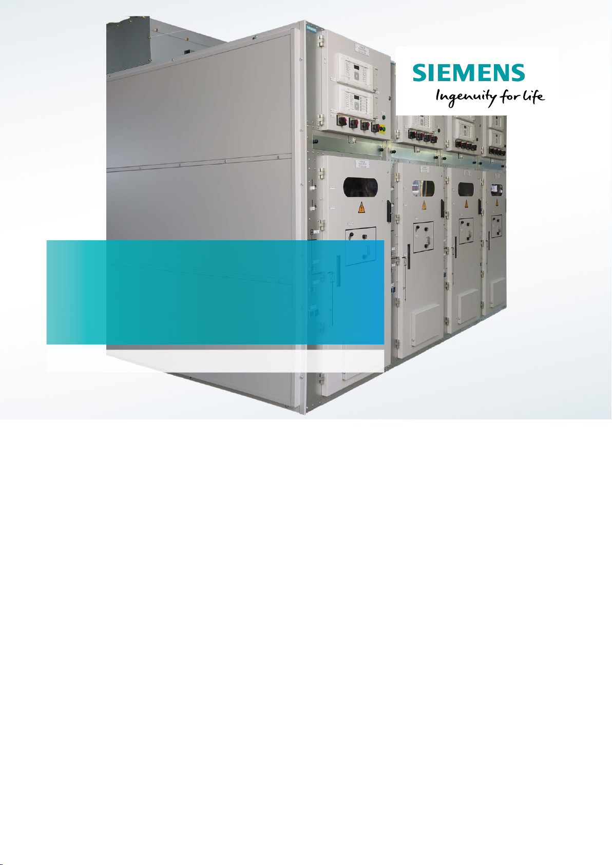
Sitras ASG25
1- and 2-pole air-insulated switchgear
for AC traction power supply
siemens.com/rail-electrication
The Sitras ASG25® air-insulated switchgear is intended for use in 1- and 2-pole
AC traction power supply systems. It is a type-tested, metal-enclosed switchgear
for indoor installation.
The general concept of the SitrasASG25 is based on a proven technology
offering high reliability and availability. It provides long lifetime, high number of
operating cycles, long lasting insulation properties and low life-cycle costs
Features
• High personnel safety
• High fire safety
• Environment-friendly: minimum use of materials listed in directives
67/548/EEC and 2001/59/EC
• Low life-cycle costs
• High availability
• Fast and easy replacement of the vacuum circuit-breaker by use of
tulip contacts
Page 2
Design
Mechanical design
Frame
• The base frame, door and outer walls are made of screw/
rivet connected steel sheets with 2 mm thickness
• Hinged plates (pressure relief flaps) are installed on top
for pressure relief in case of internal arc faults
• Doors and side walls are painted; galvanized steel sheets
are used for all other parts
Busbars
• Busbars are supported by standard cast-resin post
insulators and bushings
• Busbars can be easily connected by links after cubicle
arrangement on site
• Partitioning of busbar compartment by insulating plate
and bushing
• Busbars can be earthed (see option 9 on page 6)
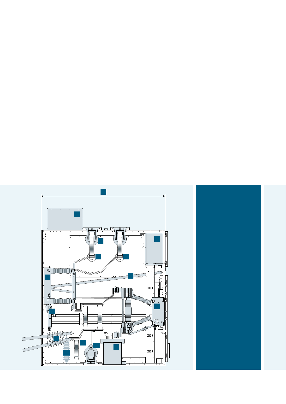
D
High voltage compartment
• Pressure resistant inspection windows for
− visible position of disconnector and earthing switch
− status indication of vacuum circuit-breaker (ON/OFF,
proven spring charging technology, operation counter)
• Insulating protection plate for safe maintenance while
busbar is energized
Low voltage compartment
Control cables for external connections are led from the
bottom to the low voltage compartment via cable duct or
through flange plate at the top.
All wirings may be provided in non-halogen variants on
request.
Service truck
Thanks to the plug-in / plug-out technology with tulip
contacts, the vacuum circuit-breaker can be fast and conveniently replaced using the easy to handle service truck.
P
9
1 1
2
3
7
12
6
11
B
5
L
1 Busbar
2 Disconnector
3 Earthing switch
4 Vacuum circuit-breaker
5 Current transformer
6 Capacitive voltage detection
system
7 Cable sealing end from rear
(Option)
9 Busbar voltage transformer
(Option)
4
11 Voltage transformer (Option)
12 Surge arrester (Option)
L Low voltage compartment
P Pressure relief channel
B Bearing for insulating
protection plate
D Depth
H1 Height switchgear
H2 Height pressure relief channel
W1 Width 1-pole version
W2 Width 2-pole version
Schematic layout of Sitras ASG25 (shown example: 2-pole version with option cable sealing end from rear)
2
Page 3
Electrical design
Cable connections
• Cable connections from bottom up to 4 x 500 mm² per
feeder
• Cable connections from rear available as an option
• Surge arrester available as an option
High voltage compartment
• Switching devices
− vacuum circuit-breaker, motor operated
− disconnector and earthing switch, manual or motor
operated
− manual emergency operation possible for all switching
devices
• Interlocking between vacuum circuit-breaker,
disconnector and earthing switch
• Measurement transformers for control and protection
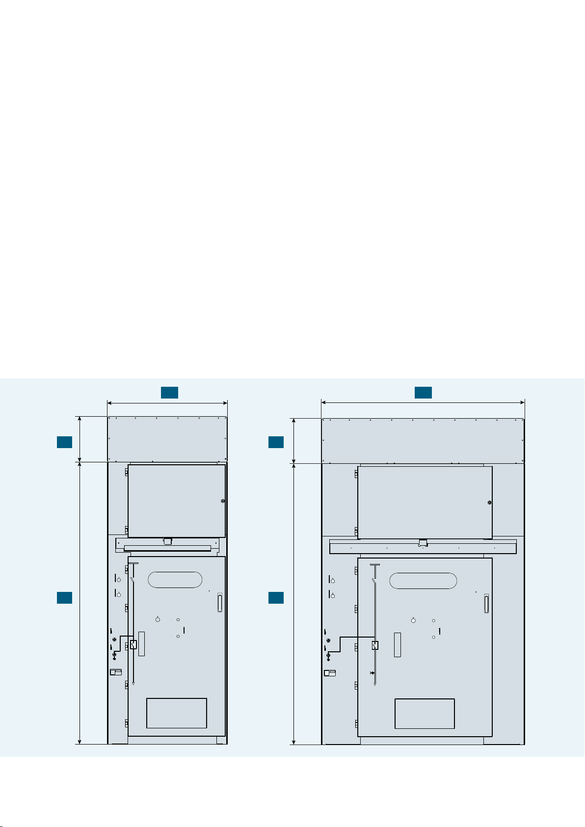
W1
Low voltage compartment
• Protection relay and user interface are installed in the
door of the low voltage compartment
• Miniature circuit-breakers and auxiliary relays are
located inside the low voltage compartment
• Connection between the vacuum circuit-breaker and the
low voltage compartment is made via a 64-pin plug
and-socket arrangement
W2
H2 H2
H1 H1
Front view of Sitras ASG25: 1-pole version (left) and 2-pole version (right)
3
Page 4

Main components
Vacuum circuit-breaker, type 3AH47
Switching capacity
• Switching sequence:
O - 0.3 s - CO - 3 min - CO (other values on request,
multiple auto-reclosing possible)
• Rated short-circuit breaking-current 25 kA with
DC component < 36 %
Operating mechanism
• Service life of 60,000 operating cycles
(maintenance-free up to 10,000 operating cycles, without time limitation under normal operating conditions)
Vacuum interrupter
• Mechanical service life of 30,000 operating cycles (main-
tenance-free)
• Electrical service life dependent on breaking current (see
diagram below)
Disconnector, type 3DA11 / 3DB11
• Service life of 10,000 operating cycles
• Integrated earthing switch, service life of 10,000
operating cycles
• Manual operating mechanism with mechanical interlock
between disconnector and earthing switch and electromagnetic interlock
• Motor-operated mechanism with electrical interlock
(option)
Function
• CLOSED: Main circuit closed between busbar and
circuit-breaker
• OPEN: Main circuit open between busbar and
circuit-breaker
• READY-TO-EARTH: Upper contact of circuit-breaker
earthed; earthing of cable by closing the circuit-breaker
Current and voltage transformer
• Cast resin type for indoor installation
• Service life ≥ 30 years
• Maintenance-free
100000
30000
10000
Permissible operating cycles –>
1000
100
50
30
10
1
1 10 502 5 25 100
Breaking current in kA (r.m.s. value) –>
Electrical service life of vacuum interrupter Sitras ASG25 2-pole version with vacuum circuit-breaker
on a service truck
4
Page 5

Technical data
Electrical data
Variant 1-pole 2-pole
Nominal voltage acc. to IEC 60850, EN 50163 [kV] 25 25
Rated insulation voltage acc. to EN 50124-1 [kV] 27.5 27.5
Rated frequency [Hz] 50 / 60 50 / 60
Rated short duration power frequency withstand voltage
to earth and across open contacts
across isolating distance
Rated lightning impulse withstand voltage
to earth and across open contacts
across isolating distance
Rated short-circuit breaking current [kA] 25 25
Rated short-time withstand current, 1 s [kA] 25 25
Rated short-circuit making current [kA] 63 63
Rated normal current [A] 1,250 / 2,000 1,250 / 2,000
Internal arc classification acc. to IEC 62271-200 IAC A FL I
LSC category / partition class LSC 2A / PI LSC 2A / PI
other values on request
[kV]
[kV]
[kV]
[kV]
25 kA 1 s IAC A FL IAe 25 kA 1 s
Ae
95
110
200
220
95
110
200
220
Mechanical data
Variant 1-pole 2-pole
Dimensions approx.
Height switchgear panel H1
Height pressure relief channel H2
Width W1 / W2
Depth D
Weight per panel [kg] approx. 1,100 approx. 1,600
Degree of protection IP4X IP4X
Permissible ambient temperature [°C] -5…+40 -5…+40
Relative humidity (non condensing) < 85 % < 85 %
General standards IEC 62271-1; IEC 62271-200 IEC 62271-1; IEC 62271-200
Standards for railway applications EN 50124; EN 50152 EN 50124; EN 50152
other values on request
[mm]
[mm]
[mm]
[mm]
2,350
380
1,000
2,150
2,350
1,700
2,150
380
5
Page 6

Application
Application examples for 1-pole version*
Section feeder panel Bus coupler panel
1
2
3
4
5
11 12 14
7
Standard equipment
Standard equipment
1 Busbar
2 Disconnector
3 Earthing switch
4 Vacuum circut-breaker
5 Current transformer
6 Capacitive voltage detection system
7 Cable sealing end
8 Voltage transformer
Optional busbar fittings
9 Busbar voltage transformer
10 Earthing switch
Optional connection fittings
11 Voltage transformer
12 Surge arrester
13 Current transformer
14 Capacitive voltage detection system
15 High-voltage fuse
Options
109
and/or and/or
and/or
1
2
3
4
Standard equipment
Metering panel
1
2
3
8
9
13
and/or
13 14
Options
10
15
* other panel types on request
6
Standard equipment
Options
Page 7

Application examples for 2-pole version*
Incoming & section feeder panel / Autotransformer panel
1
2
3
4
5
6
7
Standard equipment
Options 11, 12 only for incoming and section feeder panel
9 10
11
Options
and/or and/or
12
Section feeder panel
1
2
3
4
5
6
7
Standard equipment
9
11
Options
and/or
12
Bus coupler panel
1
2
3
4
Standard equipment
9
13
and/or
13 14
Options
Metering panel
1
2
3
8
Standard equipment
10
15
Options
7
Page 8

© Siemens Mobility GmbH 2020
All rights reserved
Sitras ASG25 / Product information
No.A6Z08110273695 / Version 2.0.3
Siemens Mobility GmbH
Otto-Hahn-Ring 6
81739 Munich
Germany
For further information please contact:
Siemens Mobility GmbH
Rail Infrastructure
Electrification
Mozartstraße 33b
91052 Erlangen
Germany
electrification.mobility@siemens.com
www.siemens.com/rail-electrification
Subject to changes and errors. The information given in this document only contains general
descriptions and/or performance features which may not always specifically reflect those
described, or which may undergo modification in the course of further development of the
products. The requested performance features are binding only when they are expressly
agreed upon in the concluded contract.
 Loading...