

Page 1
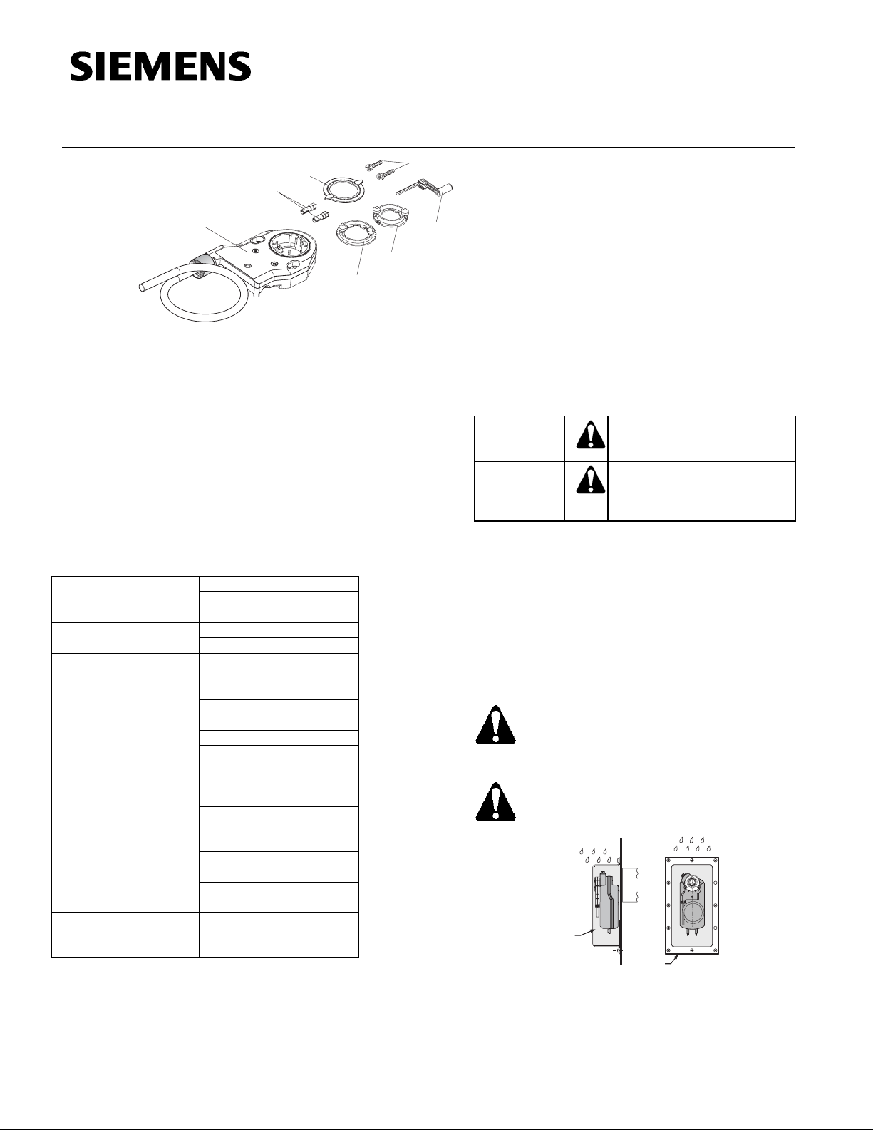
OpenAir™ External Auxiliary Switch
b
f
a
Installation Instructions
Document No. 129-420
December 13, 2004
g
e
a. External dual auxiliary switch
b. Position indicator
c. GCA/GBB/GIB position adapter
d. GMA/GEB position adapter
e. 3 mm hex key
f. Plastic mounting adapter inserts (2)
g. Threaded M5 × 25 screws (2)
EA1175R1
d
c
Figure 1. External Auxiliary Switch Kit Contents.
Product Description
The OpenAir External Auxiliary Switch (EAS) provides
switch functionality for standard model damper actuators
with easy installation for in-service units.
Product Number
ASC77.2U
Specifications
Dual Auxiliary Switches
24 Vac to 250 Vac
AC rating
DC rating
Insulation system Double insulated
Switch A
Recommended
usage
Switch B 0° to 90° with 5° intervals
Recommended
usage
Switching hysteresis 2°
Agency certification
Conduit Connection Threaded 1/2-inch
Shipping Weight 1.1 lb (0.48 kg)
AC 6A resistive
AC 2 FLA, 12 LRA
12 Vdc to 30 Vdc
DC 2A
Switch range
0° to 90° with 5° intervals
0° to 45°
45° to 90°
UL listed to UL 873
cUL certified to Canadian
Standard C22.2
No. 24-93
Electromagnetic
compatibility 89/336/EEC
Low voltage directive
73/23/EEC
NSPT, flex only
Warning/Caution Notations
WARNING:
CAUTION:
Personal injury/loss of life
may occur if you do not follow
the procedures as specified.
Equipment damage, or loss of
data may occur if you do not
follow the procedures as
specified.
Required Tools
Phillips screwdrivers
No. 2 for screws, No. 1 for adjustment
Expected Installation Time
15 minutes
Prerequisites
CAUTION:
Remove power from in-service damper
actuator before installing external
auxiliary switch.
WARNING:
Do not open the external auxiliary switch.
ASK75.3U
or
ASK75.1U
EA1191R1
ASK75.3U
ASK75.1U
or
Figure 2. NEMA Type 3R Rating Only
With Use of Weather Shield.
Item Number 129-420, Rev. 010 Page 1 of 5
Page 2
Document No. 129-420
Installation Instructions
December 13, 2004
Installation
New Actuators, Remove Pre-load
GCA, GBB, GIB GMA, GEB
EA1179R1
Figure 3. Determine Actuator Model and Orientation.
NOTE: For in-service actuators, skip Removing Pre-
load. For new actuators, remove the factoryinstalled 5° pre-load.
Removing Preload
Before the External Auxiliary Switch can be installed on
a new, out-of-the-box actuator, you must remove the
factory-installed preload.
New Non-Spring Return Actuators
1. Insert shaft adapter at position A (See Figure 4).
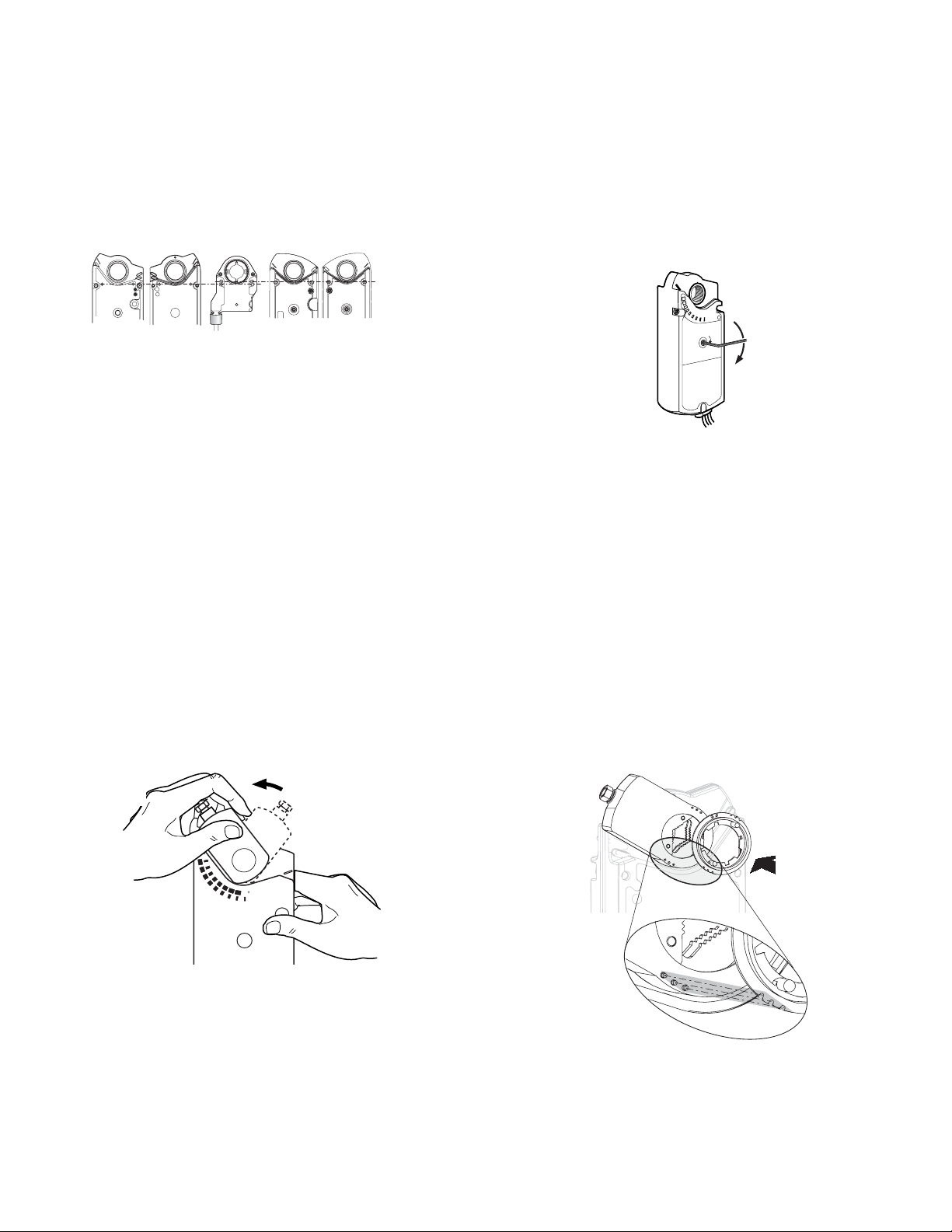
New Spring Return Actuators
1. Without the shaft adapter installed, using the hex
wrench, wind the manual override one full
revolution and release the wrench (See Figure 5).
The actuator will return to the 0° position and the
preload is now removed.
Manual
Override
1-Turn
EA1192R1
Figure 5.
2. Manually install the shaft adapter against the
external stop on the left end of the actuator. (See
position B in Figure 4.)
Removing Factory Pre-load from New SR Actuator.
Preparing the Actuator Shaft Adapter
2. Press the manual override button and move the
shaft adapter counterclockwise until actuator
reaches the internal stop (actuator will not move
past this point).
3. Remove the shaft adapter and manually reinstall it
against the external end stop at position B (See
Figure 4).
4. Proceed with EAS installation.
B
A
90
90
PUSH
EA1190R1
Figure 4.
Insert Shaft Adapter at Position A.
1. Remove the position indicator from an in-service
actuator.
2. Determine the appropriate position adapter ring
(See Figure 1).
3. Align and snap the three open notches on the edge
of the EAS position adapter ring in place over the
three raised stubs on the actuator shaft adapter.
(See Figure 6).
NOTE:
GCA/GBB/GIB
models use the
larger ring.
GMA/GEB models
use smaller ring.
See Figure 1.
EA1177R1
Figure 6. Attaching the EAS Position Adapter Ring.
Page 2 of 5 Siemens Building Technologies, Inc.
Page 3

Document No. 129-420
Installation Instructions
December 13, 2004
Short shaft applications
NOTE: The short shaft adapter is included in
the packing box with the shaft adapter.
With the short shaft adapter in place, align the
notch of the EAS over the protruding tab on the
position adapter ring and secure in place.
(See Figure 7).
ShortShaft
Adapter
EA1178R1
Figure 7. Attaching EAS to GCA/GIB/GBB Shaft Adapter.
Preparing the EAS for Mounting
2. On the back of the EAS, push the plastic inserts into
the mounting holes. (See Figure 8 and Figure 9).
2
b
f
1
EA1181R1
Figure 9. For GCA, GBB, GIB Actuators, Use the Bottom
Screw Holes.
Mounting External Auxiliary Switch to
Actuator
1. Nest the alignment peg of the EAS position adapter
ring into the notch (See Figure 10).
The EAS lies flush against the face of the actuator.
Note: GMA/GEB
actuators use top
screw holes, GCA,
GBB/GIB models
use bottom screw
holes.
3. Mount the position indicator on the face of the EAS
(See Figure 8 step 2 and Figure 9, step 2).
2
b
f
EA1182R1
Figure 8. For GMA/GEB Actuators, Use Top Screw Holes.
9.5±1.5lb-in(1.1Nm±0.2)
EA1183R1
Figure 10. Bringing the EAS and the Actuator together.
2. Secure the EAS in place with the M5×25 screws
provided. (See Figure 10).
CAUTION:
The EAS should not shift when it is
correctly installed firmly against the face
of the actuator.
The installation is complete.
Siemens Building Technologies, Inc. Page 3 of 5
Page 4

Document No. 129-420
Installation Instructions
December 13, 2004
Manual Override
NOTE: When EAS is installed, you can still access the
manual override capability as shown in Figure
11.
0
∞
EA1185R1
0∞
GBB/GIB
GEB
GMA
GCA
Figure 11. Manual Override.
Auxiliary Switches
CAUTION:
There should be no load on the actuator
when setting the auxiliary switches.
A
0∞
5∞
10∞
20∞ 30∞ 70∞ 90∞
5∞
A
S1 S1
(Q11)
(Q12)
(Q14)
S2 S3 S2 S3
EA1187R1
(Q12)
(Q11)
(Q14)
Figure 13. Example of Switches Set to 5° and 85°.
B
85∞
2∞
B
S4 S4
(Q21)
(Q22)
(Q24)
S5 S6 S5 S6
(Q22)
Wiring
WARNING:
Do not mix operations. Apply only line voltage
or only Class 2 voltages to the switching
outputs of both auxiliary switches A and B.
24Vac...250V/6(2)A
S1 S4
(Q11)
A
(Q21)
B
(Q21)
(Q24)
Setting the Switches
With the actuator in the full-closed (0°) position, press in
and turn with a Phillips screwdriver to the desired
setting. Release pressure to set the switch.
The switch is now set.
~3.5
mm
max.
10N
5
85
15
75
25
75
65
35
55
45
65
35
55
45
EA1186R1
Figure 12. Press In, Turn to Adjust, Release to Set Switch.
5
5
85
85
15
15
25
75
25
65
5
85
15
75
65
35
25
55
45
35
55
45
(Q14)
(Q12)
S2 S3 S5 S6
EA1189R1
(Q22)
Figure 14. Wiring Diagram.
Wiring Designation
Wire Code Color Switch - Function
S1 Gray/red A Input
S2 Gray/blue A – NC
S3 Gray/pink A – NO
S4 Black/red B Input
S5 Black/blue B – NC
S6 Black/pink B – NO
(Q24)
Page 4 of 5 Siemens Building Technologies, Inc.
Page 5

Dimensions
Document No. 129-420
Installation Instructions
December 13, 2004
1.2
(30,5)
4.9
(124,5)
3.7
(94)
.65
(16,5)
EA1180R1
2.0
(51,2)
3.6
(91)
1.6
(39,8)
.8
(21,5)
Figure 15. External Auxiliary Switch Dimensions in Inches (mm).
.13
(3,5)
Information in this publication is based on current specifications. The company reserves the right to make changes in specifications and models as
design improvements are introduced.
OpenAir is a trademark of Siemens Building Technologies, Inc. Other product or company names mentioned
herein may be the trademarks of their respective owners. © 2004 Siemens Building Technologies, Inc.
Siemens Building Technologies, Inc.
1000 Deerfield Parkway
Buffalo Grove, IL 60089-4513
U.S.A.
Your feedback is important to us. If you have comments
about this document, please send them to
technical.editor@siemens.com
Document No. 129-420
Country of Origin: US
Page 5 of 5
 Loading...