

Page 1

ARCADIS Avantic
ARCADIS Avantic
English
Operator Manual
SPR2-330.620.01.02.02
ARCADIS Avantic
English
Operator Manual
SPR2-330.620.01.02.02
English
Operator Manual
SPR2-330.620.01.02.02
ARCADIS Avantic
English
Operator Manual
SPR2-330.620.01.02.02
ARCADIS Avantic
English
Operator Manual
SPR2-330.620.01.02.02
ARCADIS Avantic
English
Operator Manual
SPR2-330.620.01.02.02
ARCADIS Avantic
English
Operator Manual
SPR2-330.620.01.02.02
ARCADIS Avantic
English
Operator Manual
SPR2-330.620.01.02.02
Page 2

Page 3
Operator Manual
ARCADIS Avantic
VB 13 C
SP
Page 4

© Siemens AG 2006
All rights reserved
Contact address
Siemens AG Siemens AG, Medical Solutions
Wittelsbacherplatz 2Special Systems
D-80333 Muenchen Henkestraße 127
Germany D-91052 Erlangen
Germany
The original language of this document is English.
SPR2-330.620.01.02.02
Printed in Germany
AG 03/06
SP
Page 5

ARCADIS Avantic
Overall Table of Contents
Register
System Operator Manual
Overall Table of Contents
Register 1: Safety
General safety information..................................................................................................................... 3
Personal safety .................................................................................................................................... 17
Equipment safety................................................................................................................................. 41
Register 2: System Description
Description of functions......................................................................................................................... 3
Operation ............................................................................................................................................... 9
Register 3: Patient Data
Introduction to patient registration......................................................................................................... 3
Emergency registration.......................................................................................................................... 5
Registering a new patient ...................................................................................................................... 9
Registering a known patient ................................................................................................................ 13
Patient registration configuration ......................................................................................................... 19
Introduction to the Patient Browser..................................................................................................... 25
Searching for and displaying patient data ............................................................................................ 29
Updating and deleting data .................................................................................................................. 37
Patient Browser Configuration ............................................................................................................. 51
Register 4: Examination
Safety information relating to the examination procedure ..................................................................... 3
The Examination task card ..................................................................................................................... 5
Performing an examination .................................................................................................................... 9
References task card ........................................................................................................................... 21
Displaying reference images................................................................................................................ 25
Native Task Card .................................................................................................................................. 29
Displaying native images ..................................................................................................................... 30
Reports ................................................................................................................................................ 33
ARCADIS Avantic
SPR2-330.620.01.02.02 1
of 2
Page 6

ARCADIS Avantic
Overall Table of Contents
Register 5: Viewing
Introduction............................................................................................................................................ 3
Loading and displaying images ............................................................................................................ 13
Scrolling and selecting images............................................................................................................. 19
Editing images ..................................................................................................................................... 33
2D Evaluation (option) .......................................................................................................................... 47
DSA Evaluation .................................................................................................................................... 57
Saving, transferring, documenting, closing images ............................................................................. 61
Viewing configuration .......................................................................................................................... 69
Register 6: Filming/Printing and Archiving
Introduction to filming/printing ............................................................................................................... 3
Automatic / manual filming .................................................................................................................... 9
Viewing and processing film sheets and images................................................................................. 17
Changing film settings for a film job .................................................................................................... 33
Controlling data transfer....................................................................................................................... 43
Configuration for filming/printing ......................................................................................................... 51
Introduction to archiving ...................................................................................................................... 63
Archiving data ...................................................................................................................................... 67
Exporting data ...................................................................................................................................... 71
Import/export in the file system........................................................................................................... 79
Controlling data transfer....................................................................................................................... 85
Configuration for archiving ................................................................................................................... 91
Register 7: Configuration
Examination configuration...................................................................................................................... 3
Register 8: Technical Description
Curves and diagrams ............................................................................................................................. 3
Technical data ...................................................................................................................................... 15
Labels .................................................................................................................................................. 19
Register 9: Maintenance
Functional and safety checks................................................................................................................. 3
Service support via network connection ................................................................................................ 6
Cleaning and disinfection ....................................................................................................................... 9
Register 10: Accessories and Options
Accessories............................................................................................................................................ 3
Operator Manual
2
of 2 SPR2-330.620.01.02.02
Page 7

SiemensSP04Cs2
Operator Manual
ARCADIS Avantic
Safety
SP
08.03
SPR2-330.620.01.02.02EnglishEnglish
Cs2
, 7777SP MSVersion 04
Page 8

Please observe the
Safety register
This must be studied thoroughly before system startup.
The original version of this Operator Manual was written in the
English language.
© Siemens AG 2006
All rights reserved
Siemens AG, Wittelsbacherplatz 2, D-80333 Muenchen, Germany
Contact information: Siemens AG, Medical Solutions, Special Systems
Henkestraße 127, D-91052 Erlangen, Germany
Order no.: SPR2-330.620.01.02.02
SP
Printed in Germany
AG 03/06
Page 9

General safety information
Information about this Operator Manual . . . . . . . . . . . . . . . . . . . . . . 3
Warnings . . . . . . . . . . . . . . . . . . . . . . . . . . . . . . . . . . . 3
General information . . . . . . . . . . . . . . . . . . . . . . . . . . . . . 4
Information about correcting errors . . . . . . . . . . . . . . . . . . . . . 4
Names and parameters . . . . . . . . . . . . . . . . . . . . . . . . . . . 4
Laws and regulations . . . . . . . . . . . . . . . . . . . . . . . . . . . . . . . . 5
Scope . . . . . . . . . . . . . . . . . . . . . . . . . . . . . . . . . . . . . . . . 5
Software . . . . . . . . . . . . . . . . . . . . . . . . . . . . . . . . . . . . . . 6
Equipotential bonding . . . . . . . . . . . . . . . . . . . . . . . . . . . . . . . . 7
Electromagnetic compatibility . . . . . . . . . . . . . . . . . . . . . . . . . . . 7
Use in connection with high frequency . . . . . . . . . . . . . . . . . . . . . . . 7
Maintenance and check up . . . . . . . . . . . . . . . . . . . . . . . . . . . . . 8
Failures . . . . . . . . . . . . . . . . . . . . . . . . . . . . . . . . . . . . . . . 9
Error messages at the C-arm system . . . . . . . . . . . . . . . . . . . . 9
System messages on the monitor . . . . . . . . . . . . . . . . . . . . . . 11
Malfunction of electrics . . . . . . . . . . . . . . . . . . . . . . . . . . . . . . 12
Switching to emergency power supply . . . . . . . . . . . . . . . . . . . 12
Disconnecting the power supply plug . . . . . . . . . . . . . . . . . . . . 12
Emergency STOP . . . . . . . . . . . . . . . . . . . . . . . . . . . . . . . . . 13
Fire protection . . . . . . . . . . . . . . . . . . . . . . . . . . . . . . . . . . 14
Explosion protection . . . . . . . . . . . . . . . . . . . . . . . . . . . . . . . 14
Overload protection . . . . . . . . . . . . . . . . . . . . . . . . . . . . . . . . 15
Table of Contents
Personal safety
Open heart and skull examinations . . . . . . . . . . . . . . . . . . . . . . . . 17
Crushing hazards on the C-arm system . . . . . . . . . . . . . . . . . . . . . 17
Crushing hazards on the monitor trolley . . . . . . . . . . . . . . . . . . . . . 19
Mechanical damage . . . . . . . . . . . . . . . . . . . . . . . . . . . . . . . 19
Radiation protection . . . . . . . . . . . . . . . . . . . . . . . . . . . . . . . 20
Location and size of the relevant operating areas . . . . . . . . . . . . . . . . 21
X-ray tube assembly at the bottom . . . . . . . . . . . . . . . . . . . . . 21
X-ray tube assembly at the top . . . . . . . . . . . . . . . . . . . . . . . 25
X-ray tube assembly horizontal . . . . . . . . . . . . . . . . . . . . . . . 29
X-ray tube assembly lateral 45° . . . . . . . . . . . . . . . . . . . . . . . 33
Image intensifier lateral 42° . . . . . . . . . . . . . . . . . . . . . . . . . 37
Radiation interruption for all operating modes . . . . . . . . . . . . . . . . 40
ARCADIS Avantic
SPR2-330.620.01.02.02 1
of 46
Page 10

Table of Contents
Equipment safety
Positioning the C-arm . . . . . . . . . . . . . . . . . . . . . . . . . . . . . . . 41
Installation, repair . . . . . . . . . . . . . . . . . . . . . . . . . . . . . . . . . 42
Original accessories . . . . . . . . . . . . . . . . . . . . . . . . . . . . . . . 42
Combination with other products/components . . . . . . . . . . . . . . . . . . 43
Attachment of dedicated options . . . . . . . . . . . . . . . . . . . . . . . . . 43
General safety requirements . . . . . . . . . . . . . . . . . . . . . . . . . 43
Tilting resistance; mechanical strength; central ray migration . . . . . . . . 43
Attachment . . . . . . . . . . . . . . . . . . . . . . . . . . . . . . . . . 44
Attenuation equivalent . . . . . . . . . . . . . . . . . . . . . . . . . . . . 44
Weight counterbalance . . . . . . . . . . . . . . . . . . . . . . . . . . . 44
Image quality . . . . . . . . . . . . . . . . . . . . . . . . . . . . . . . . . 44
Electromagnetic compatibility . . . . . . . . . . . . . . . . . . . . . . . . 45
Additional safety information . . . . . . . . . . . . . . . . . . . . . . . . 45
Disposal . . . . . . . . . . . . . . . . . . . . . . . . . . . . . . . . . . . . . . 46
Operator Manual
2
of 46 SPR2-330.620.01.02.02
Page 11

Safety
General safety information
Information about this Operator Manual
Proper use of this equipment presupposes that the operating personnel are
familiar with the Operator Manual. This manual must be studied in detail prior to
starting up the system. Special attention must be given to the following sections:
❏ Safety information
❏ Functional and safety checks
❏ Personal s afety
❏ Equipment safety
The operating personnel must be instructed in the proper operation of the equipment. Training must be repeated as required at appropriate intervals.
We recommend simulating emergency conditions during training so that appropriate corrective measures can be taught.
Warnings
Warning Warning is used to indicate the presence of a hazard which can cause personal
injury or death.
WARNING
At first the source of danger is stated.
Then possible consequences are pointed out.
◆ In conclusion you receive information on how to rule out any danger.
Caution Caution is used to indicate the presence of a hazard which can cause damage to
the equipment if this is used improperly.
CAUTION
At first the source of danger is stated.
Then possible consequences are pointed out.
◆ In conclusion you receive information on how to rule out any danger.
ARCADIS Avantic
SPR2-330.620.01.02.02 3
of 46
Page 12
Safety
General information
Note Note is used to notify users of operator information which is important but not
hazard-related.
Notes are marked with an exclamation mark “ !” and printed in italics.
Information about correcting errors
Information on how to solve problems that might occur when performing operating steps is given at the end of the relevant instructions.
Names and parameters
All names and data of patients and institutions that are used in this operator
manual are entirely fictional.
Any resemblance to names of existing people or institutions past or present is
entirely coincidental.
All parameters and images shown in this manual are examples. Only the parameters displayed by your system are definite.
Operator Manual
4
of 46 SPR2-330.620.01.02.02
46
Page 13

Safety
Laws and regulations
If legally binding regulations govern the installation and/or operation of the
system, it is the responsibility of the installer and/or the operator to observe these
regulations.
In all countries, the legally established regulations are to be observed. Deviating
from this Operator Manual, values may be set according to country-specific regulations.
This product is provided with a CE marking in accordance with the
provisions of Directive 93/42/EEC of June 14th, 1993 concerning
medical devices.
Data related to individual persons are subject to data protection. Ensure
compliance with all applicable laws and regulations.
Legally required tests must be performed at the specified intervals. These tests
include, for example,
❏ Constancy test according to the X-ray ordinance (§16 RöV) in the
Federal Republic of Germany.
❏ Tests based on DHHS guidelines (Department of Health and Human Services)
where applicable.
Scope
This Operator Manual is valid for the following product:
❏ ARCADIS Avantic
ARCADIS Avantic
SPR2-330.620.01.02.02 5
of 46
Page 14

Safety
Software
The system and user software used in this product is protected by copyright.
WARNING
Use of unreleased software or manipulations/modifications to released software
can lead to system malfunctions.
This can result in injury to the patient and/or damage to the equipment!
◆ Only software released by Siemens for use with this product may be used.
CAUTION
Impermissible or faulty manipulations/modifications to the software or to the
connection between the ARCADIS Avantic system and the power supply can lead
to malfunctioning of the system.
Unauthorized access!
◆ Make sure all necessary precautions are taken (with the existing level of security) when changing a functionality or factory-set configuration.
CAUTION
Reduced system performance due to overload of the network environment.
Unexpected system behavior!
◆ Only use the ARCADIS Avantic system in a secure and load-adapted network.
Operator Manual
6
of 46 SPR2-330.620.01.02.02
46
Page 15

Safety
Equipotential bonding
Products for which equipotential bonding is required may only be operated in
medical facilities where supplementary equipotential bonding has been installed
and tested according to DIN VDE 0107/10.94 section 4 or the relevant countryspecific regulations.
Electromagnetic compatibility
This medical device complies with the requirements of the applicable standard on
electromagnetic compatibility (EMC).
(→ see Operator Manual “Information on electromagnetic compatibility”)
However, we wish to inform you that other mobile electronic devices such as
radio telephones (mobile phones) exceed the radiation limits specified in the EMC
standard and can therefore disturb functions of your medical device.
Use in connection with high frequency
The following regulations for use must be observed:
❏ IEC/TR 1289-1 / 07.94/
High frequency surgical equipment - Part 1: Operation
❏ IEC/TR 1289-2 /08.94/
High frequency surgical equipment - Part 2: Maintenance
ARCADIS Avantic
SPR2-330.620.01.02.02 7
of 46
Page 16
Safety
Maintenance and check up
Before using the equipment for examination, the user must ascertain that all
safety-relevant devices function properly and that the system is ready for operation.
Wear and tear The system is subject to mechanical and electrical wear and tear. In the interest
of the safety of patients, operating personnel and third persons, maintenance and
safety checks must be carried out every 12 months to maintain the operational
safety and reliability of the product.
Please observe the relevant information in the
(→
Register 9: Maintenance)
CAUTION
Mechanical damage and damage to the system electrics due to improper use and
excessive load on the system.
Injury to operating personnel, patients or third persons and damage to the
product!
◆ If necessary, have the system checked more frequently.
◆ Ensure that any defects are repaired professionally.
Image quality Maintenance should include checking the image quality. Maintenance at regular
intervals is recommended to always ensure best image quality.
To ensure optimal image quality, have the following functions checked in particular as part of regular maintenance:
Pixelshift, image rotation, noise reduction, edge enhancement, subtraction,
Roadmapping.
Performing mainte-
nance
Maintenance work should be performed by trained technical personnel only. If
you do not have a maintenance contract, please contact Siemens Customer
Service.
If national laws or regulations specify more frequent checking and/or maintenance, this must be observed.
Operator Manual
8
of 46 SPR2-330.620.01.02.02
46
Page 17
Safety
Failures
In the event of malfunctions of the ARCADIS Avantic system, call SIEMENS
Customer Service.
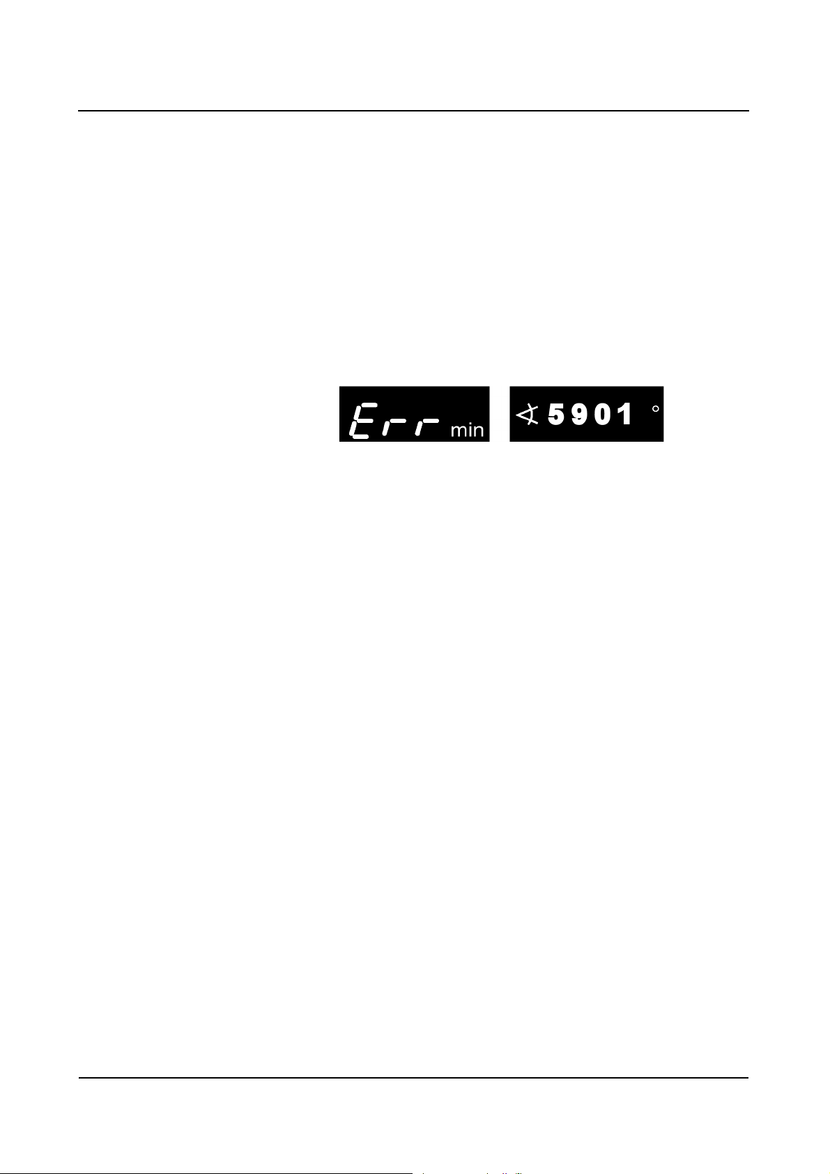
Error messages at the C-arm system
When a malfunction is detected, the ARCADIS Avantic system is disabled. An
error message is displayed on the control panel of the C-arm system:
In addition, a malfunction is also displayed on the left monitor:
❏ All vital system functions are automatically checked each time the ARCADIS
Avantic is switched on.
❏ During routine operation, the ARCADIS Avantic is continuously monitored.
❏ Temporary error messages, such as No. 5901, can be canceled by pressing any
button on the C-arm system (except vertical up/down movements and C-arm
brakes).
❏ Non-temporary error messages, such as No. 5015 or 5016, cannot be
canceled. If these errors occur, radiation release is no longer possible.
Please notify Customer Service immediately.
ARCADIS Avantic
SPR2-330.620.01.02.02 9
of 46
Page 18

Safety
Error messages 7309 (tube unit iris collimator) and 7409 (TV camera iris) are
temporary error messages that can lead to unnecessary radiation exposure of the
user and patient if treatment is continued.
If errors occur repeatedly, switch off the ARCADIS Avantic and notify Customer
Service. Have the following information ready:
❏ Error number
❏ Operating mode selected
❏ Was radiation activated when the error occurred?
❏ Is the error related to an operating process?
In case of a malfunction or failure of the radiation indicator, please notify Siemens
Customer Service.
Operator Manual
10
of 46 SPR2-330.620.01.02.02
46
Page 19
Safety
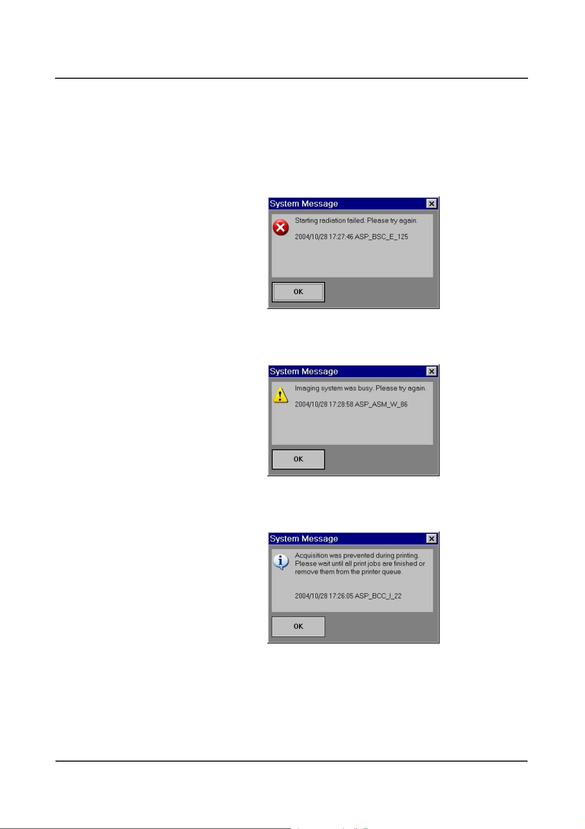
System messages on the monitor
Three different types of system messages can appear on the monitor. The type
of message is identified by a corresponding symbol (top left).
❏ Example of an error message:
❏ Example of a warning:
❏ Example of information:
You must confirm error messages with the OK button or the radiation release
button to be able to resume your work. However, warnings and information do not
disable radiation release.
ARCADIS Avantic
SPR2-330.620.01.02.02 11
of 46
Page 20

Safety
Malfunction of electrics
In case of danger for patients and operating personnel (e.g. if there is no live
image on the monitor and the radiation indicator is on despite this) or danger for
the product, you must disconnect the power plug immediately. The ARCADIS
Avantic will be shut down completely and disconnected from the power supply.
This will
❏ switch off radiation
❏ abort the current system program
❏ abort and cancel current operating sequences
❏ deleting all image information not saved to a hard disk.
Only after the cause of the hazard has been clearly identified and remedied may
the system be reconnected to the power supply. In all other cases, e.g. system
malfunction, contact Siemens Customer Service immediately.
Switching to emergency power supply
If a power interruption lasts longer than 8 ms, the ARCADIS Avantic can switch
off. In this case the ARCADIS Avantic must be switched on again after switching
to the emergency power supply.
In case of a power failure, a signal sounds (up to 10 min.) when the system
switches to uninterruptible power supply (UPS).
Disconnecting the power supply plug
After disconnecting the power plug, voltage is supplied to the imaging system
and the left monitor by the uninterruptible power supply (UPS) until the ARCADIS
Avantic switches off completely.
When the plug is pulled out, switching to the uninterruptible power supply causes
an acoustic signal to be emitted. The UPS switches off after 10 min. at the latest.
As soon as mains supply is restored, the battery of the UPS is recharged.
Please remember that the UPS battery life is limited.
Operator Manual
12
of 46 SPR2-330.620.01.02.02
46
Page 21
Safety
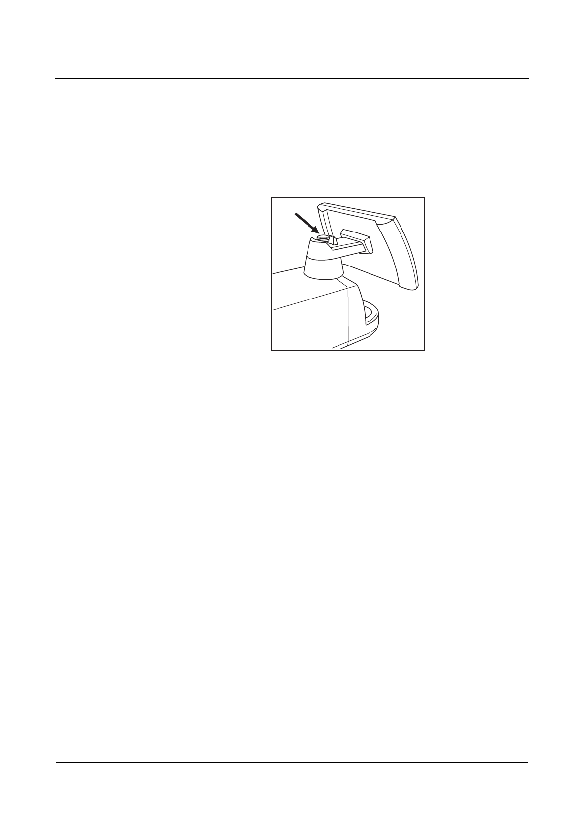
Emergency STOP
Please immediately press the red EMERGENCY STOP button (arrow) on the electronics unit of the C-arm system when a dangerous situation results from motorized movements.
❏ Motorized vertical movement is then disabled immediately.
❏ All other system functions remain unaffected by this.
Unlock the button only after the danger has clearly been eliminated.
❏ The button can be unlocked by gently turning it clockwise.
ARCADIS Avantic
SPR2-330.620.01.02.02 13
of 46
Page 22

Safety
Fire protection
WARNING
In case of fire
A fire or smoldering fire can produce toxic gases or fumes!
◆ Immediately switch off the ARCADIS Avantic.
◆ Pull the power cable out of the wall outlet.
◆ Inform all personnel of the correct procedures in case of fire as part of occu-
pational safety training.
Please inform our Customer Service prior to starting up the ARCADIS Avantic
again as it may require refurbishing due to damage caused by fire.
Explosion protection
WARNING
Ignitable concentration of anesthetic gases in the examination room.
Explosion hazard!
◆ The ARCADIS Avantic must not be operated in such an environment.
Operator Manual
14
of 46 SPR2-330.620.01.02.02
46
Page 23

Safety
Overload protection
Prolonged continuous radiation at maximum tube load is permissible in fluoroscopy mode. However, this can cause the X-ray tube assembly to heat up. For this
reason, the X-ray tube assembly has a thermal monitor. If necessary, power is
reduced in all operating modes, in SUB/Roadmap with the next new scene/mask.
CAUTION
Heating up of the X-ray tube assembly due to continuous radiation
Burns of the skin may occur!
◆ At a temperature of ≥ 50 °C the single-tank housing must not come into
contact with the patient's skin.
The following operating states can occur:
If the temperature rises to ≥ 50°C or if a certain power limit of the X-ray tube is
exceeded:
❏ the temperature indicator on the control panel of the C-arm system lights up.
❏ the LED on the key for high-contrast fluoroscopy flashes.
❏ the imaging system displays a message in the status bar.
❏ the system switches to characteristic SR1.
❏ the previously set characteristic can be reselected for each new radiation
request by actuating the High Contrast key. On actuation of the key an
acoustic alarm sounds (4- beeps).
❏ all radiation for which the previously set characteristic was reselected is
counted.
If the temperature rises to ≥ 60°C or if a certain power limit of the X-ray tube is
exceeded:
❏ the temperature indicator on the control panel of the C-arm system flashes
continuously.
❏ the LED on the key for high-contrast fluoroscopy flashes.
❏ the imaging system displays a message in the status bar.
❏ the system switches to characteristic SR2 and the maximum frame rate in the
PFC and DCM modes is reduced by one step.
❏ the previously set characteristic can be reselected for each new radiation
request by actuating the High Contrast key. On actuation of the key an
acoustic alarm sounds (4- beeps).
❏ all radiation for which the previously set characteristic was reselected is
counted.
ARCADIS Avantic
SPR2-330.620.01.02.02 15
of 46
Page 24

Safety
If the temperature rises to ≥ 70°C or if the maximum power stage is exceeded:
❏ radiation is aborted and cannot be released again.
❏ the kV/mA display flashes no later than 30 s after radiation is disabled.
❏ a message window is displayed on the imaging system.
If a third power limit value is exceeded at a temperature of < 70°C, radiation
release is still possible. On actuation of the High Contrast key, you can switch
over to characteristic SR1 for the next radiation cycle. This is indicated by an
acoustic signal (8 beeps).
Operator Manual
16
of 46 SPR2-330.620.01.02.02
46
Page 25

Safety
Personal safety
Open heart and skull examinations
If an approved system is used alone or with other equipment for cardiac or cranial
examinations, a conductive connection must be made between the
system and a potential equalization point, e.g. the tabletop.
(→ Register 2: System Description: page 10)
Only then may the patient be connected to the device.
Crushing hazards on the C-arm system
Correct handling of the C-arm system requires that operating personnel and
patients use only the grips provided for this purpose. Where this is not possible,
monitor the points of potential crush injury between movable system parts and
their guide openings.
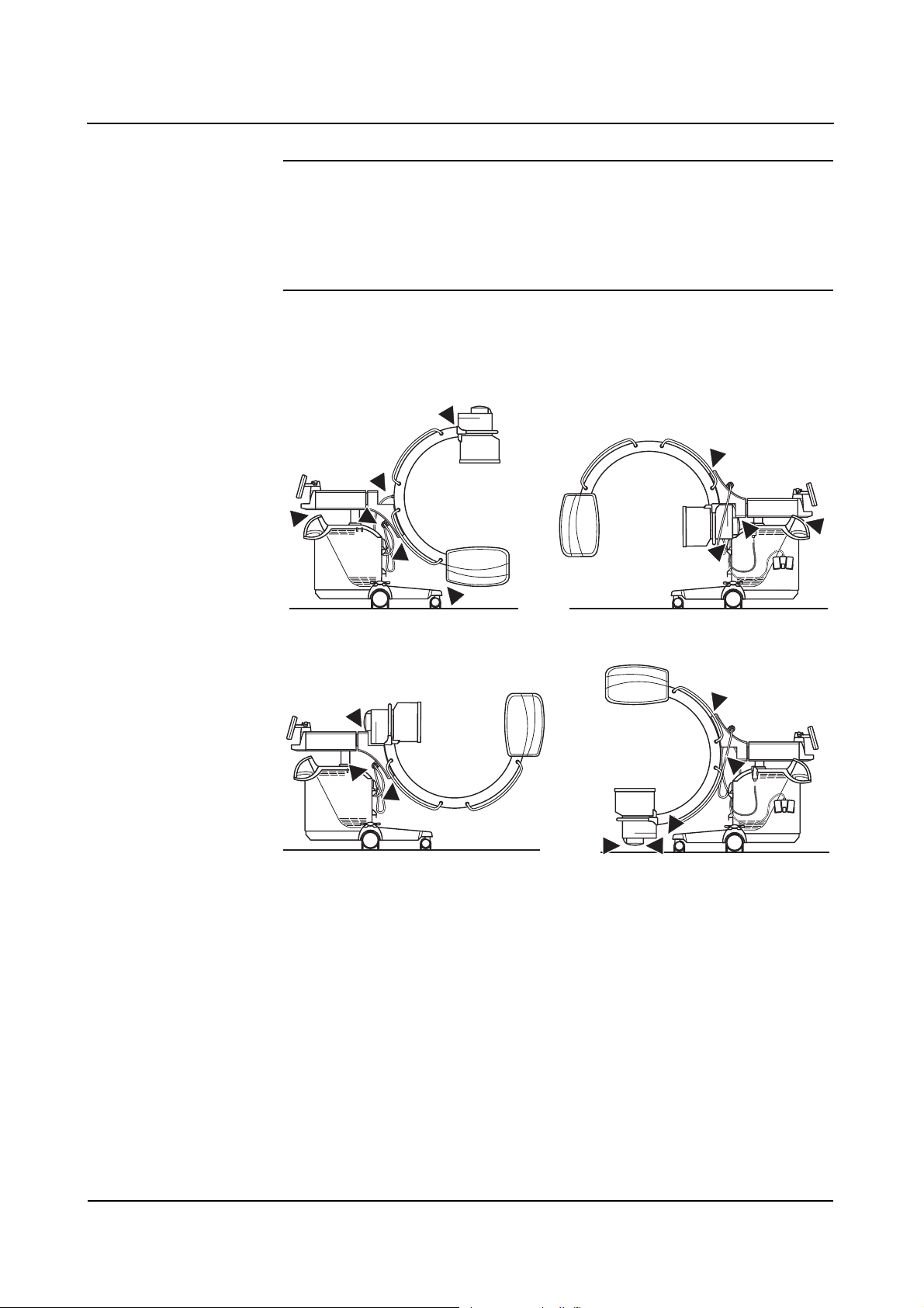
WARNING
Moving and braking the C-arm (see Fig. 1).
Risk of crushing hands!
◆ Please make sure that your hands are not in the travel path of system parts.
WARNING
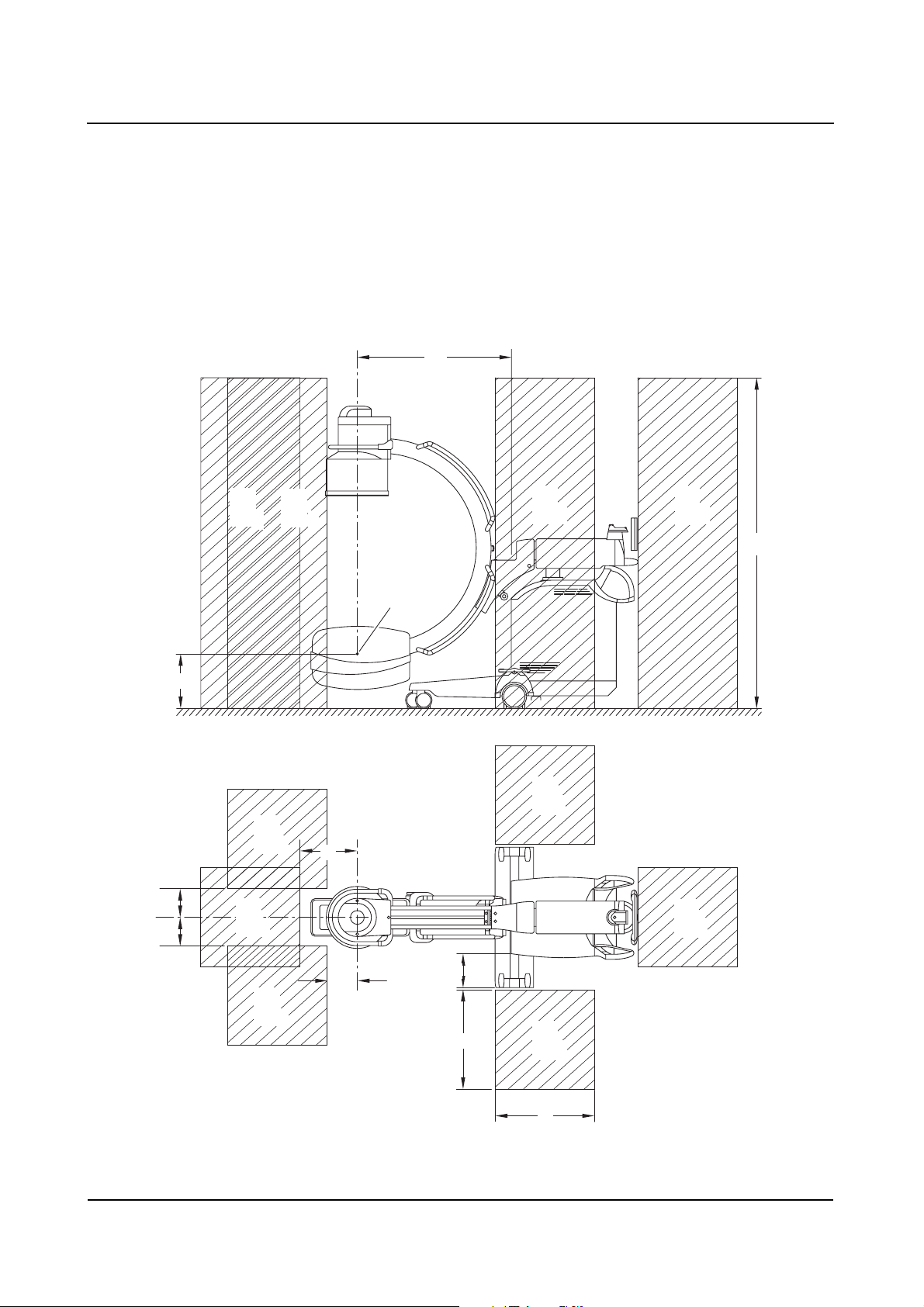
Maximum lowering of the C-arm (see Fig. 2)
Risk of crushing feet!
◆ Please watch your feet when the C-arm is being lowered fully, since there may
not be sufficient clearance left between the I.I. and the floor.
ARCADIS Avantic
SPR2-330.620.01.02.02 17
of 46
Page 26
Safety
WARNING
Maximum lowering of the C-arm (see Fig. 2)
Radiation can be released inadvertently!
◆ Please make sure that the footswitch is not located underneath the C-arm.
The system areas marked in the drawings indicate points of crushing or impact
hazards for the patient or operating personnel.
(1)
(1)
(1)
(2)
(1) Potential danger points when moving and braking the C-arm
(2) Potential danger points when the C-arm is lowered fully
Operator Manual
18
of 46 SPR2-330.620.01.02.02
46
Page 27
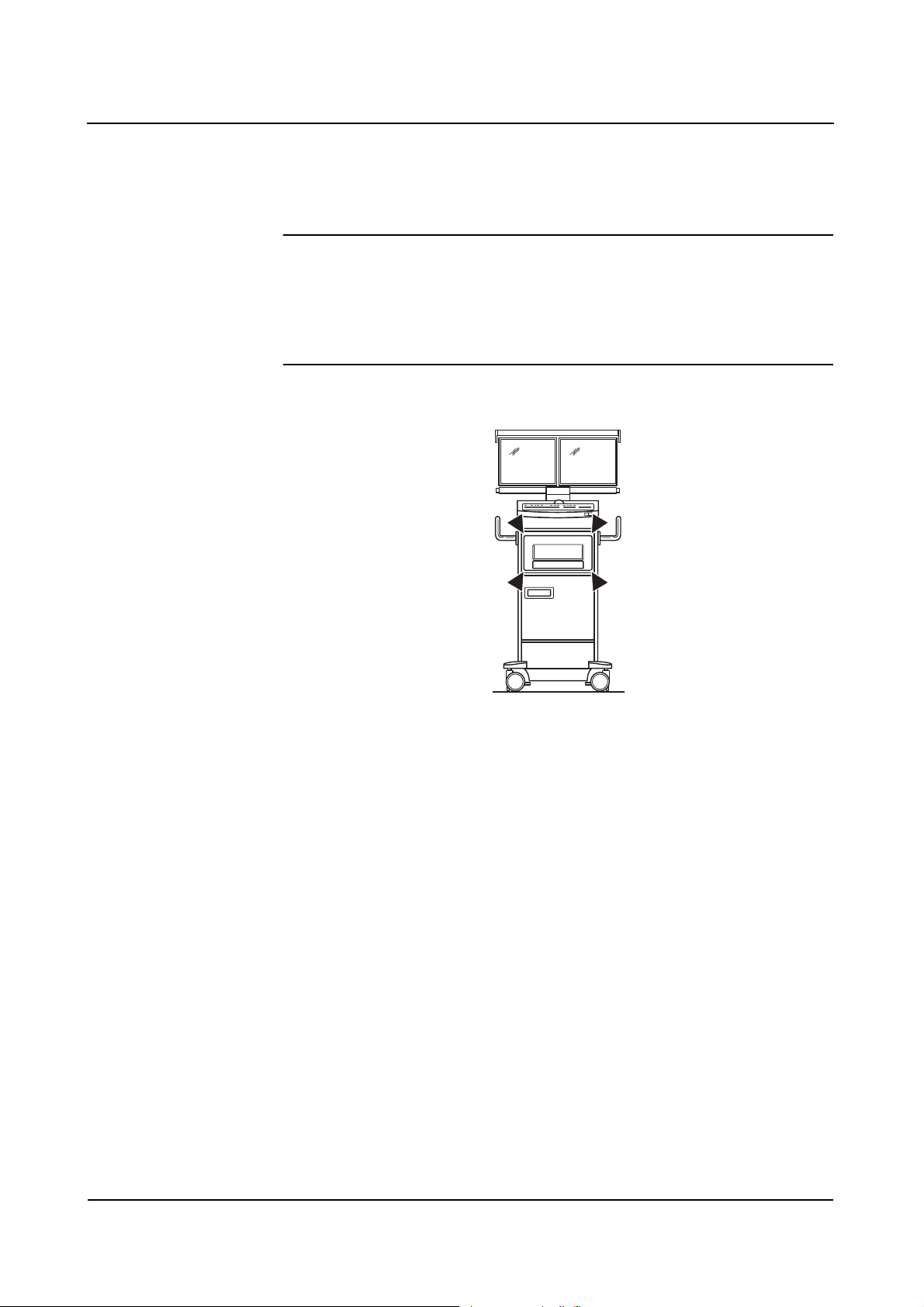
Crushing hazards on the monitor trolley
Your monitor trolley can optionally be equipped with a printer.
CAUTION
Moving the printer out or in
Risk of crushing hands!
◆ Mind your hands when moving the printer out of or into its location.
Safety
Mechanical damage
To avoid injuries to the patient, operating personnel or third parties, mechanical
damage to the system must be repaired by authorized service personnel.
ARCADIS Avantic
SPR2-330.620.01.02.02 19
of 46
Page 28
Safety
Radiation protection
Automatic dose rate control contributes considerably to the reduction of radiation
exposure for the patient and the operator.
Nevertheless, observe the following important notes in order to keep the dose
absorbed by the patient as low as possible.
For the patient ❏ Keep the radiation field as small as possible.
❏ Provide the best possible protection for reproductive organs (gonad protective
caps or lead-rubber covers) during exposure in the vicinity of these organs.
For the operating
personnel
For patients and oper-
ating personnel
❏ When releasing the exposure, the operator must keep a sufficient safety
distance from the X-ray tube assembly.
❏ Wear protective clothing in the control area during an examination.
❏ Wear a radiation-monitoring badge or use a pen dosimeter.
❏ Keep the fluoroscopic time as short as possible.
❏ Maintain the maximum possible source-skin distance.
Additional objects in the beam path may result in increased scattered radiation.
Please be aware that certain materials in the X-ray beam (e.g. parts of an operating table) may impair the X-ray image due to imaging of contours and inclusions
in these materials. In rare cases this can result in incorrect diagnosis. This
material may also lead to higher radiation exposure.
Operator Manual
20
of 46 SPR2-330.620.01.02.02
46
Page 29
Safety
Location and size of the relevant operating
areas
X-ray tube assembly at the bottom
94
1818
28
A
A
1
A
1
A
2
B
B
2
2
2
Fokus
Focal point
35
B
B
1
200
1
23
60
B
60
2
A
16
2
ARCADIS Avantic
SPR2-330.620.01.02.02 21
of 46
Page 30

Safety
Scattered radiation in the main operating area according to EN 60601-1-3
Height
above floor
[cm]
10 1,7604 1,9224 0,0216 0,9828
20 2,6244 2,3544 0,0216 1,0692
30 3,1068 3,1428 0,0216 1,116
40 3,5028 4,3524 0,0324 1,1232
50 4,6188 5,9508 0,0324 1,188
60 5,8032 7,5924 0,054 1,2528
70 6,858 9,1476 0,1512 1,2096
80 7,8912 11,142 0,2052 1,1664
90 8,6184 13,6188 0,2052 1,0872
100 8,2872 14,4612 0,1944 0,9288
110 6,6312 10,1304 0,1836 0,7992
120 5,94 7,4592 0,1836 0,7452
130 4,7088 4,41 0,1836 0,72
140 2,2356 1,3716 0,1728 0,6732
Measurement A1
[mGy/h]
Measurement A2
[mGy/h]
Measurement B1
[mGy/h]
Measurement B2
[mGy/h]
150 0,9828 1,1772 0,1728 0,6048
160 0,5472 0,8316 0,162 0,54
170 0,3996 0,5652 0,162 0,4536
180 0,3348 0,4428 0,1512 0,378
190 0,2808 0,3348 0,1404 0,3132
200 0,2592 0,27 0,1296 0,2592
Tolerance of air kerma measurements ±5%
❏ Measurement A1: Operating area A1
continuous fluoroscopy 125 kV, 3.2 mA; C-arm vertical, X-ray tube assembly at
the bottom, with scattered radiation grid
❏ Measurement A2: Operating area A2
continuous fluoroscopy 125 kV, 3.2 mA; C-arm vertical, X-ray tube assembly at
the bottom, with scattered radiation grid
❏ Measurement B1: Operating area B1
continuous fluoroscopy 125 kV, 3.2 mA; C-arm vertical, X-ray tube assembly at
the bottom, with scattered radiation grid
❏ Measurement B2: Operating area B2
continuous fluoroscopy 125 kV, 3.2 mA; C-arm vertical, X-ray tube assembly at
the bottom, with scattered radiation grid
Operator Manual
22
of 46 SPR2-330.620.01.02.02
46
Page 31

cm above ground
200
190
180
170
160
150
140
130
120
110
100
90
A1
80
70
60
50
40
30
20
10
0
A2
0 2 4 6 8 10 12 14 16 18 20
mGy/h (air kerma power)
Safety
❏ Measurement A1
continuous fluoroscopy 125 kV, 3.2 mA
❏ Measurement A2
continuous fluoroscopy 125 kV, 3.2 mA
ARCADIS Avantic
SPR2-330.620.01.02.02 23
of 46
Page 32

Safety
cm above ground
200
190
180
170
160
150
140
130
120
110
100
90
80
70
60
50
40
30
20
10
0
0
B1
B2
1
mGy/h (air kerma power)
2
❏ Measurement B1
continuous fluoroscopy 125 kV, 3.2 mA
❏ Measurement B2
continuous fluoroscopy 125 kV, 3.2 mA
Operator Manual
24
of 46 SPR2-330.620.01.02.02
46
Page 33

160
A
1 2
X-ray tube assembly at the top
94
Fokus
A
Focal point
B
2
B
Safety
1
200
1818
A
A
1
A
B
2
2
35
B
1
16
2
23
60
B
60
2
ARCADIS Avantic
SPR2-330.620.01.02.02 25
of 46
Page 34

Safety
Scattered radiation in the main operating area according to EN 60601-1-3
Height
above floor
[cm]
10 0,3132 0,4968 0,0216 0,3888
20 0,378 0,6048 0,0216 0,4536
30 0,5508 0,8316 0,0216 0,5184
40 0,9612 1,2636 0,0216 0,594
50 2,3976 2,2032 0,0324 0,648
60 4,4028 4,8636 0,054 0,6876
70 5,346 7,7868 0,0756 0,702
80 6,2352 11,8692 0,1188 0,774
90 7,8264 15,8868 0,1944 0,918
100 8,1324 14,562 0,2376 1,0584
110 7,5672 11,9736 0,2592 1,1232
120 6,7428 10,1412 0,2592 1,1664
130 5,9868 8,6472 0,2592 1,1772
140 4,806 6,7824 0,2484 1,134
Measurement A1
[mGy/h]
Measurement A2
[mGy/h]
Measurement B1
[mGy/h]
Measurement B2
[mGy/h]
150 3,7296 4,9032 0,2268 1,0908
160 3,3732 3,474 0,2268 1,0692
170 2,7288 2,6208 0,2268 1,026
180 1,8252 2,0736 0,2268 0,9288
190 1,5372 1,6848 0,2268 0,864
200 1,3284 1,4148 0,2268 0,7992
Tolerance of air kerma measurements ±5%
❏ Measurement A1: Operating area A1
continuous fluoroscopy 125 kV, 3.2 mA; C-arm vertical, X-ray tube assembly at
the top, with scattered radiation grid
❏ Measurement A2: Operating area A2
continuous fluoroscopy 125 kV, 3.2 mA; C-arm vertical, X-ray tube assembly at
the top, with scattered radiation grid
❏ Measurement B1: Operating area B1
continuous fluoroscopy 125 kV, 3.2 mA; C-arm vertical, X-ray tube assembly at
the top, with scattered radiation grid
❏ Measurement B2: Operating area B2
continuous fluoroscopy 125 kV, 3.2 mA; C-arm vertical, X-ray tube assembly at
the top, with scattered radiation grid
Operator Manual
26
of 46 SPR2-330.620.01.02.02
46
Page 35

cm above ground
200
190
180
170
160
150
140
130
120
110
100
90
80
70
60
50
40
30
20
10
0
A1
A2
0 2 4 6 8 10 12 14 16 18 20
mGy/h (air kerma power)
Safety
❏ Measurement A1
continuous fluoroscopy 125 kV, 3.2 mA
❏ Measurement A2
continuous fluoroscopy 125 kV, 3.2 mA
ARCADIS Avantic
SPR2-330.620.01.02.02 27
of 46
Page 36

Safety
cm above ground
200
190
180
170
160
150
140
130
120
110
100
90
80
70
60
50
40
30
20
10
0
0
B1
B2
1
mGy/h (air kerma power)
2
❏ Measurement B1
continuous fluoroscopy 125 kV, 3.2 mA
❏ Measurement B2
continuous fluoroscopy 125 kV, 3.2 mA
Operator Manual
28
of 46 SPR2-330.620.01.02.02
46
Page 37

X-ray tube assembly horizontal
168
109
48
Safety
112
A
A
A
2
2
Fokus
Focal point
B
B
2
2
B
1
200
1
1818
A
1
23
A
2
60
B
60
2
B
1
ARCADIS Avantic
SPR2-330.620.01.02.02 29
of 46
Page 38

Safety
Scattered radiation in the main operating area according to EN 60601-1-3
Height
above floor
[cm]
10 0,8424 0,8856 0,0216 0,3564
20 0,9396 1,1232 0,0324 0,3888
30 1,0584 1,4256 0,0324 0,4212
40 1,1988 1,8576 0,0324 0,4644
50 1,3608 2,43 0,0324 0,486
60 1,5336 3,2616 0,054 0,5184
70 1,6956 4,5144 0,0972 0,54
80 1,8576 6,2676 0,0864 0,5832
90 2,0196 8,5968 0,054 0,6156
100 2,0916 11,4156 0,0432 0,6264
110 2,1816 13,2156 0,0324 0,6264
120 2,1816 12,5604 0,0432 0,6156
130 2,0952 10,206 0,0432 0,594
140 1,9332 7,8372 0,0432 0,5724
Measurement A1
[mGy/h]
Measurement A2
[mGy/h]
Measurement B1
[mGy/h]
Measurement B2
[mGy/h]
150 1,8036 5,8068 0,0756 0,5508
160 1,836 4,2876 0,1296 0,5292
170 1,6956 3,1968 0,1404 0,5292
180 1,5228 2,43 0,1404 0,5292
190 1,3392 1,89 0,1296 0,5184
200 1,1916 1,5228 0,1296 0,5184
Tolerance of air kerma measurements ±5%
❏ Measurement A1: Operating area A1
continuous fluoroscopy 125 kV, 3.2 mA; C-arm horizontal, X-ray tube assembly
horizontal, with scattered radiation grid
❏ Measurement A2: Operating area A2
continuous fluoroscopy 125 kV, 3.2 mA; C-arm horizontal, X-ray tube assembly
horizontal, with scattered radiation grid
❏ Measurement B1: Operating area B1
continuous fluoroscopy 125 kV, 3.2 mA; C-arm horizontal, X-ray tube assembly
horizontal, with scattered radiation grid
❏ Measurement B2: Operating area B2
continuous fluoroscopy 125 kV, 3.2 mA; C-arm horizontal, X-ray tube assembly
horizontal, with scattered radiation grid
Operator Manual
30
of 46 SPR2-330.620.01.02.02
46
Page 39

cm above ground
200
190
180
170
160
150
140
130
120
110
100
90
80
70
60
50
40
30
20
10
0
A1
A2
0 2 4 6 8 10 12 14 16 18 20
mGy/h (air kerma power)
Safety
❏ Measurement A1
continuous fluoroscopy 125 kV, 3.2 mA
❏ Measurement A2
continuous fluoroscopy 125 kV, 3.2 mA
ARCADIS Avantic
SPR2-330.620.01.02.02 31
of 46
Page 40

Safety
cm above ground
200
190
180
170
160
150
140
130
120
110
100
90
80
70
60
50
40
30
20
10
0
0
B1
B2
1
mGy/h (air kerma power)
2
❏ Measurement B1
continuous fluoroscopy 125 kV, 3.2 mA
❏ Measurement B2
continuous fluoroscopy 125 kV, 3.2 mA
Operator Manual
32
of 46 SPR2-330.620.01.02.02
46
Page 41

X-ray tube assembly lateral 45°
167
139
106
45
Safety
69
1818
A
A
B
2
A
1
1
2
A
Fokus
Focal point
B
2
2
B
B
1
200
1
23
A
2
60
B
60
2
ARCADIS Avantic
SPR2-330.620.01.02.02 33
of 46
Page 42

Safety
Scattered radiation in the main operating area according to EN 60601-1-3
Height
above floor
[cm]
10 0,9936 1,4472 0,0216 0,4968
20 1,134 1,6416 0,0216 0,5076
30 1,2852 1,9656 0,0216 0,5508
40 1,4472 2,4876 0,0432 0,5724
50 1,6308 3,2472 0,054 0,5832
60 1,836 4,7736 0,0648 0,5832
70 2,0196 6,9516 0,0972 0,6372
80 2,214 10,4544 0,1404 0,702
90 2,9952 13,0104 0,1728 0,756
100 2,9556 14,8716 0,1728 0,7992
110 2,6784 17,0316 0,162 0,7884
120 2,5056 18,0828 0,162 0,7344
130 2,332 15,9228 0,1512 0,6372
140 2,1708 10,8864 0,1512 0,5076
Measurement A1
[mGy/h]
Measurement A2
[mGy/h]
Measurement B1
[mGy/h]
Measurement B2
[mGy/h]
150 1,9548 6,1776 0,1404 0,4104
160 1,6848 3,9276 0,1404 0,3456
170 1,404 2,9592 0,1404 0,3132
180 1,1556 2,2356 0,1296 0,2808
190 0,9504 1,6884 0,1296 0,2592
200 0,5292 1,2528 0,1296 0,2376
Tolerance of air kerma measurements ±5%
❏ Measurement A1: Operating area A1
continuous fluoroscopy 125 kV, 3.2 mA; C-arm vertical, X-ray tube assembly
lateral 45°, with scattered radiation grid
❏ Measurement A2: Operating area A2
continuous fluoroscopy 125 kV, 3.2 mA; C-arm vertical, X-ray tube assembly
lateral 45°, with scattered radiation grid
❏ Measurement B1: Operating area B1
continuous fluoroscopy 125 kV, 3.2 mA; C-arm vertical, X-ray tube assembly
lateral 45°, with scattered radiation grid
❏ Measurement B2: Operating area B2
continuous fluoroscopy 125 kV, 3.2 mA; C-arm vertical, X-ray tube assembly
lateral 45°, with scattered radiation grid
Operator Manual
34
of 46 SPR2-330.620.01.02.02
46
Page 43

cm above ground
200
190
180
170
160
150
140
130
120
110
100
90
80
70
60
50
40
30
20
10
0
A1
A2
0 2 4 6 8 10 12 14 16 18 20
mGy/h (air kerma power)
Safety
❏ Measurement A1
continuous fluoroscopy 125 kV, 3.2 mA
❏ Measurement A2
continuous fluoroscopy 125 kV, 3.2 mA
ARCADIS Avantic
SPR2-330.620.01.02.02 35
of 46
Page 44

Safety
cm above ground
200
190
180
170
160
150
140
130
120
110
100
90
80
70
60
50
40
30
20
10
0
0
B1
0,5
B2
1
mGy/h (air kerma power)
❏ Measurement B1
continuous fluoroscopy 125 kV, 3.2 mA
❏ Measurement B2
continuous fluoroscopy 125 kV, 3.2 mA
Operator Manual
36
of 46 SPR2-330.620.01.02.02
46
Page 45

Image intensifier lateral 42°
155
45
42
Safety
48
1818
A
A
B
2
A
A
2
2
Fokus
Focal point
B
2
1
1
B
B
1
200
1
23
A
2
60
B
60
2
ARCADIS Avantic
SPR2-330.620.01.02.02 37
of 46
Page 46

Safety
Scattered radiation in the main operating area according to EN 60601-1-3
Height
above floor
[cm]
10 0,9072 1,3716 0,0648 1,2204
20 1,0152 1,62 0,0648 1,296
30 1,1016 2,0088 0,0648 1,3932
40 1,1556 2,5596 0,0648 1,5228
50 1,2096 3,2292 0,0648 1,674
60 1,242 4,1364 0,1512 1,8036
70 1,404 5,3244 0,3636 1,8792
80 1,6524 6,75 0,4644 1,9008
90 1,8684 8,0892 0,468 1,8684
100 1,836 8,19 0,4644 1,782
110 1,3176 10,3356 0,4428 1,7064
120 0,8136 11,7396 0,432 1,6416
130 0,5292 5,5404 0,3996 1,4364
140 0,4536 2,4948 0,3672 1,2096
Measurement A1
[mGy/h]
Measurement A2
[mGy/h]
Measurement B1
[mGy/h]
Measurement B2
[mGy/h]
150 0,3888 1,4796 0,324 1,0692
160 0,2484 1,0044 0,2916 0,918
170 0,1044 0,7596 0,2592 0,756
180 0,0864 0,5832 0,2484 0,6264
190 0,0756 0,4752 0,2484 0,5184
200 0,0864 0,3996 0,2412 0,4536
Tolerance of air kerma measurements ±5%
❏ Measurement A1: Operating area A1
continuous fluoroscopy 125 kV, 3.2 mA; C-arm vertical, image intensifier lateral
42°, with scattered radiation grid
❏ Measurement A2: Operating area A2
continuous fluoroscopy 125 kV, 3.2 mA; C-arm vertical, image intensifier lateral
42°, with scattered radiation grid
❏ Measurement B1: Operating area B1
continuous fluoroscopy 125 kV, 3.2 mA; C-arm vertical, image intensifier lateral
42°, with scattered radiation grid
❏ Measurement B2: Operating area B2
continuous fluoroscopy 125 kV, 3.2 mA; C-arm vertical, image intensifier lateral
42°, with scattered radiation grid
Operator Manual
38
of 46 SPR2-330.620.01.02.02
46
Page 47

cm above ground
5
200
190
180
170
160
150
140
130
120
110
100
90
80
70
60
50
40
30
20
10
0
A1
A2
0 5 10 1
mGy/h (air kerma power)
Safety
❏ Measurement A1
continuous fluoroscopy 125 kV, 3.2 mA
❏ Measurement A2
continuous fluoroscopy 125 kV, 3.2 mA
ARCADIS Avantic
SPR2-330.620.01.02.02 39
of 46
Page 48

Safety
cm above ground
200
190
180
170
160
150
140
130
120
110
100
90
80
70
60
50
40
30
20
10
0
0
B1
B2
1
mGy/h (air kerma power)
2
❏ Measurement B1
continuous fluoroscopy 125 kV, 3.2 mA
❏ Measurement B2
continuous fluoroscopy 125 kV, 3.2 mA
Radiation interruption for all operating modes
The hand switch as well as the footswitch are designed as push buttons.
By releasing the respective operating element, radiation in fluoroscopy mode is
interrupted immediately or on completion of the storage image.
Operator Manual
40
of 46 SPR2-330.620.01.02.02
46
Page 49

Safety
Equipment safety
Positioning the C-arm
The maneuverability of the C-arm may cause the image intensifier or single tank
to collide with the patient or the patient table when the ARCADIS Avantic is not
operated as specified.
Safety stop for hori-
zontal movement
Brakes Make sure the brakes are applied after adjusting the C-arm position.
Tr a n s p o r t When moving or transporting the C-arm system please take special care that the
If the C-arm- is in an unfavorable horizontal position (support arm in the inner area
0-8), there is a danger of collision between the image intensifier/single tank and
the base of the -C-arm system during orbital movements. This can cause damage
to the components affected.
For this reason the zero position for moving the support arm has a safety stop.
You will therefore have to override a slight resistance at the 0 position, if you want
to move the support arm from the outer area (12–0) into the collision area (0–8).
system parts do not collide with an obstacle. This could also result in accidental
radiation release or an impairment of the image quality under certain circumstances.
ARCADIS Avantic
SPR2-330.620.01.02.02 41
of 46
Page 50

Safety
Installation, repair
Modifications or upgrades to the product must comply with legal regulations as
well as generally accepted engineering standards.
As manufacturer, SIEMENS will not be held responsible for the safety features,
reliability and performance of the product if:
❏ the product is used in a manner other than that specified in the Operator
Manual;
❏ installation, upgrades, resetting or repairs are performed by personnel not
authorized by Siemens.
❏ components affecting product safety are not replaced with original Siemens
spare parts.
❏ the electrical wiring in the rooms containing the system does not meet the
specifications of DIN VDE 0107 or the corresponding local regulations.
If desired, we will provide the technical documentation for the product. However,
this does not imply authorization to undertake repairs.
We cannot be held responsible for repairs made without our express written
approval.
When any work is performed on the product, we would recommend that you
obtain a certificate indicating the nature and scope of the work performed. The
certificate should include any changes in rated parameters or operating ranges as
well as the date, the name of the company and a signature.
Original accessories
For safety reasons, only approved original accessories from Siemens or
accessories from other manufacturers approved by Siemens AG, Medical
Solutions Group, may be used with this product.
The operator is liable for any risks associated with the use of accessories not
approved by Siemens.
Operator Manual
42
of 46 SPR2-330.620.01.02.02
46
Page 51

Safety
Combination with other products/components
To ensure the required safety, only products/components expressly approved by
SIEMENS AG, Medical Solutions Group, may be used in combination with this
system.
Regarding the attachment of non-Siemens products to the image intensifier,
please refer to
(→ page 43)
Additional components that are brought into the beam path (e.g. positioning aids)
will attenuate radiation and degrade image quality.
Attachment of dedicated options
The attachment of certain (dedicated) options is permitted only if the following
conditions are complied with:
General safety requirements
The use of accessories that do not comply with the relevant safety requirements
of this system can result in a reduced safety level of the combined system.
When choosing accessories, the following aspects must be considered in particular:
❏ Use of accessories close to the patient.
❏ Proof that the accessories have been safety tested according to the applicable
IEC 60601-1 guideline and/or the IEC 60601-1-1 harmonized national standard.
Tilting resistance; mechanical strength; central ray migration
To comply with the tilting resistance, mechanical strength and the central ray
migration standards (IEC 60601-1, IEC 60601-2-32, UL60601-1, 4 times load, IEC
60601-1-3), the addition a l weight attached to the image intensifier must not
exceed 4.5 kg (10 lbs).
If these conditions are not fulfilled, the function may be impaired.
ARCADIS Avantic
SPR2-330.620.01.02.02 43
of 46
Page 52

Safety
Attachment
When a dedicated option is used on the image intensifier, it must be ensured that
there is no danger due to insufficient or incorrect attachment.
Attenuation equivalent
According to IEC 60601-1-3, inadequate attenuation of the X-ray beam by materials between the patient and image receptor (here: I.I.) must be avoided.
Documented proof by the manufacturer is recommended.
Any auxiliary devices located in the beam path for calibration/adjustment of the
dedicated options must be removed before operating the ARCADIS Avantic.
Image quality can be impaired by placing materials directly in front of the image
intensifier, or the applied dose is increased by the automatic adjustment. Additional objects in the beam path may result in increased scattered radiation.
Weight counterbalance
Attachment of additional load on the image intensifier or tube assembly side
means the loss of weight counterbalance and can lead to unwanted, unexpected
or erratic movement of the C-arm.
Users must be alerted to this by a warning label. The responsibility for affixing the
corresponding warning label lies with the company that attaches the dedicated
option to the C-arm.
Image quality
The attachment of a dedicated option, such as a navigation system, must not
affect image quality (impairment of the diagnosis).
After maintenance or service work, the correct function of the non-Siemens
system on the image intensifier (e.g. 2D navigation) must be tested.
Operator Manual
44
of 46 SPR2-330.620.01.02.02
46
Page 53

Safety
Electromagnetic compatibility
EN 60601-1-2 must be observed in order to comply with the limit values for electromagnetic compatibility.
Additional safety information
❏ Risk of injury due to sharp edges must be avoided.
❏ To avoid thermal overloading of components and short circuits, EN 60601-1
Section 7 and, if appropriate, UL 60601-1 must be complied with.
❏ Connecting external loads to the power supply of the C-arm system is not
permitted.
❏ We recommend that users in the EU have the relevant manufacturer of the
accessory operated by you confirm the CE Declaration of Conformity
according to Appendix II, MDD and the Declaration of Compatibility according
to Article 12, MDD. In countries outside the EU the relevant national regulations must be observed.
Product liability and warranty are restricted or expire if the above listed conditions
and limit values are not complied with when attaching equipment.
For non-Siemens options we generally accept no liability.
ARCADIS Avantic
SPR2-330.620.01.02.02 45
of 46
Page 54

Safety
Disposal
There may be local regulations governing the disposal of your system:
❏ If you want to remove the product from service, take into consideraton that
there may be local regulations and laws governing its disposal. To ensure that
these legal regulations are complied with and to avoid potential environmental
hazards which may be caused by the disposal of your product, we recommend
that you consult Siemens Customer Service.
❏ The disposal of batteries and packing material must be performed according
to the national regulation in a non-polluting way.
❏ For further information about disposal of the equipment, please refer to the
technical documentation.
Operator Manual
46
of 46 SPR2-330.620.01.02.02
46
Page 55

SiemensSP04Cs2
Operator Manual
ARCADIS Avantic
System Description
SP
08.03
SPR2-330.620.01.02.02EnglishEnglish
Cs2
, 7777SP MSVersion 04
Page 56

Please observe the
Safety register
This must be studied thoroughly before system startup.
The original version of this Operator Manual was written in the
English language.
© Siemens AG 2006
All rights reserved
Siemens AG, Wittelsbacherplatz 2, D-80333 Muenchen, Germany
Contact information: Siemens AG, Medical Solutions, Special Systems
Henkestraße 127, D-91052 Erlangen, Germany
Order no.: SPR2-330.620.01.02.02
SP
Printed in Germany
AG 03/06
Page 57

Description of functions
Use . . . . . . . . . . . . . . . . . . . . . . . . . . . . . . . . . . . . . . . . . 3
Equipment overview . . . . . . . . . . . . . . . . . . . . . . . . . . . . . . . . 3
Operating modes . . . . . . . . . . . . . . . . . . . . . . . . . . . . . . 4
Options . . . . . . . . . . . . . . . . . . . . . . . . . . . . . . . . . . . 4
C-arm system . . . . . . . . . . . . . . . . . . . . . . . . . . . . . . . . . . . . 5
Control and display panel on the C-arm system . . . . . . . . . . . . . . . 6
Monitor trolley . . . . . . . . . . . . . . . . . . . . . . . . . . . . . . . . . . . 7
Keyboard at the monitor trolley . . . . . . . . . . . . . . . . . . . . . . . 8
Operation
Starting operation . . . . . . . . . . . . . . . . . . . . . . . . . . . . . . . . . . 9
Connecting the C-arm system with the monitor trolley . . . . . . . . . . . 9
Establishing the equipotential bonding connection . . . . . . . . . . . . . 10
Switchin the ARCADIS Avantic on . . . . . . . . . . . . . . . . . . . . . . 11
C-arm movements . . . . . . . . . . . . . . . . . . . . . . . . . . . . . . . . 12
Operating the electromechanical brakes . . . . . . . . . . . . . . . . . . . 12
Lifting and lowering the C-arm . . . . . . . . . . . . . . . . . . . . . . . . 13
Moving the C-arm horizontally . . . . . . . . . . . . . . . . . . . . . . . . 15
Swivelling the C-arm . . . . . . . . . . . . . . . . . . . . . . . . . . . . . 16
Angulating the C-arm . . . . . . . . . . . . . . . . . . . . . . . . . . . . 17
Orbital movement of the C-arm . . . . . . . . . . . . . . . . . . . . . . . 18
Preparing exposure . . . . . . . . . . . . . . . . . . . . . . . . . . . . . . . . 19
Removing the I.I. grid (only pediatrics) . . . . . . . . . . . . . . . . . . . . 19
Positioning the C-arm . . . . . . . . . . . . . . . . . . . . . . . . . . . . 20
Collimator setting . . . . . . . . . . . . . . . . . . . . . . . . . . . . . . 21
Image quality . . . . . . . . . . . . . . . . . . . . . . . . . . . . . . . . . 23
Image display . . . . . . . . . . . . . . . . . . . . . . . . . . . . . . . . 24
Positioning an image for fluoroscopy . . . . . . . . . . . . . . . . . . . . 25
Operating mode . . . . . . . . . . . . . . . . . . . . . . . . . . . . . . . 26
Setting the X-ray parameters manually . . . . . . . . . . . . . . . . . . . 32
Radiation release . . . . . . . . . . . . . . . . . . . . . . . . . . . . . . . . . 34
Using the hand switch . . . . . . . . . . . . . . . . . . . . . . . . . . . . 34
Using the footswitch . . . . . . . . . . . . . . . . . . . . . . . . . . . . . 36
Switch off . . . . . . . . . . . . . . . . . . . . . . . . . . . . . . . . . . . . . 37
Switching the system off . . . . . . . . . . . . . . . . . . . . . . . . . . 37
Reactivating the system . . . . . . . . . . . . . . . . . . . . . . . . . . . 39
Transport . . . . . . . . . . . . . . . . . . . . . . . . . . . . . . . . . . . . . 40
Transport and parking position of the C-arm system . . . . . . . . . . . . 40
Monitor trolley transport position . . . . . . . . . . . . . . . . . . . . . . 43
Table of Contents
ARCADIS Avantic
SPR2-330.620.01.02.02 1
of 44
Page 58

Table of Contents
Operator Manual
2
of 44 SPR2-330.620.01.02.02
Page 59

System Description
Description of functions
Use
The ARCADIS Avantic is a mobile X-ray system designed for use in surgery,
trauma centers, endoscopy and ambulatory patient care. ARCADIS Avantic offers
the following operating modes for its wide application spectrum: Digital Radiography, Fluoroscopy, Pulsed Fluroscopy as well as Subtraction / Roadmap and
Digital Cine Mode (DCM) as an option.
The ARCADIS Avantic is especially suitable for use in cardiac/vascular surgery.
Equipment overview
The ARCADIS Avantic consists of a C-arm system and a monitor trolley.
(1) (2)
(1) C-arm chassis with a 33 cm image intensifier and double-focus rotating
anode tube with generator
(2) Monitor trolley with keyboard, mouse, two TFT displays, CD R/W drive and
memory for 40,000 images
ARCADIS Avantic
SPR2-330.620.01.02.02 3
of 44
Page 60

System Description
Operating modes
The ARCADIS Avantic has the following operating modes:
❏ Continuous Fluoroscopy (CFC)
❏ Pulsed fluoroscopy (PFC) with 8 f/s
❏ Digital Radiography (DR)
Options
The following options are available for the ARCADIS Avantic:
❏ additional operating modes Subtraction and Roadmap
❏ additional operating mode Digital Cine Mode (DCM) with up to 30 f/s
❏ Pulsed Fluoroscopy (PFC) 15 f/s
❏ Fluoro Loop
❏ 2 TFT High-contrast black/white displays (alternative to TFT color displays)
❏ Monitor Out Live
❏ Monitor Out Live & Reference
❏ DICOM Standard (Send/Receive, Storage Commitment, Print)
❏ DICOM Query/Retrieve (enhancement of DICOM Standard)
❏ DICOM Worklist (enhancement of DICOM Standard)
❏ DICOM MPPS (enhancement of DICOM standard)
❏ DICOM Advanced (Send/Receive, Storage Commitment, Print, Query/
Retrieve, Worklist, MPPS)
❏ 2D measuring function (to measure angles and distances)
❏ HIPAA (Health Insurance Portability and Accountability Act)
❏ Local paper printer
❏ Local film printer
❏ Dose measuring chamber for dose area product/air kerma
❏ Integrated I.I. laser aimer
❏ Single-tank laser targeting device
❏ Multifunctional footswitch (with extended functionality)
❏ Grounding cable
❏ DHHS spacer
Operator Manual
4
of 44 SPR2-330.620.01.02.02
Page 61

System Description
❏ Sterile covers for the image intensifier, X-ray tube assembly and C-arm
❏ Clamp
C-arm system
The C-arm system comprises the following components:
(5)
(4)
(3)
(2)
(1)
(1) Electronics unit
(2) Lifting column
(3) Control and display panel (rotatable by ± 135°)
(4) Horizontal support arm
(5) C-arm
(6) Image intensifier with integrated TV camera
(6)
(7)
(7) Single tank with X-ray tube unit and integrated collimator
ARCADIS Avantic
SPR2-330.620.01.02.02 5
of 44
Page 62

System Description
Control and display panel on the C-arm system
On the C-arm system you can find the control and display panel with membrane
keys and digital displays for performing your examinations.
The individual keys and displays are grouped by their functions in different areas.
(1) Vertical movement of the C-arm
(2) Radiation indicator, X-ray tube assembly temperature
(3) Releasing/locking the C-arm brakes
(4) Image rotation
(5) Selecting the operating mode
(6) Laser light localizer On/Off, metal function On/Off
(7) Selecting image parameters (high-contrast fluoroscopy, image quality, image
display)
(8) Selecting and displaying exposure parameters
(9) Collimator setting
(10) Image postprocessing
(11) Radiation time
(12) Image selection, storing and printing
Operator Manual
6
of 44 SPR2-330.620.01.02.02
Page 63

Monitor trolley
(1)
System Description
(2)
(3)
(4)
(5)
(6)
(1) Monitor A (left); Monitor B (right)
(2) Radiation indicator
(3) Keyboard and mouse
(4) Compartment or space for options
(5) Compartment or space for options (e.g. printer)
(6) CD R/W drive
(2)
(7)
(8)
(9)
(7) On/Off button of the ARCADIS Avantic
(8) grab handles or push handles
(9) front wheels with brakes
back wheels with direction locks
ARCADIS Avantic
SPR2-330.620.01.02.02 7
of 44
Page 64

System Description
Keyboard at the monitor trolley
The application software for preparing (e.g. entering patient data) and evaluating
examinations is operated by the keyboard at the monitor trolley.
(1) Alphanumeric keyboard
(2) Cursor keys
(3) Symbol keypad
(4) Function keys
Operator Manual
8
of 44 SPR2-330.620.01.02.02
Page 65

System Description
Operation
Starting operation
Connecting the C-arm system with the monitor trolley
The C-arm system is connected to the monitor trolley with a cable.
The monitor trolley may only be connected to the corresponding C-arm system.
If the monitor trolley is connected to the wrong C-arm system, an error message
is displayed during system startup.
Before starting the ARCADIS Avantic, please make sure that the cables are
straight (without loops).
Do not lay connection cables parallel to other cables.
1
(1) Lever
◆ Turn the lever of the central plug all the way counterclockwise.
◆ Plug the central plug into the socket on the left side of the C-arm system.
◆ Turn the lever approx. ¾ turns clockwise until it audibly locks into place and
cannot be turned any further.
– The monitor trolley is connected to the C-arm system.
ARCADIS Avantic
SPR2-330.620.01.02.02 9
of 44
Page 66

System Description
Establishing the equipotential bonding connection
The ARCADIS Avantic can be connected to a protective earth terminal via the
equal potential connector on the C-arm system. This will ensure that the
ARCADIS Avantic has the same electrical potential as other units connected to
the same protective earth terminal.
When performing cardiac examinations or examinations of the open skull, an
additional grounding cable according to DIN 57107/VDE107 must be routed in
rooms of Application Group 2.
◆ Clamp the grounding cable to the front face of the C-arm system (arrow) and
to an equipotential bonding point in the patient vicinity.
– Equipotential bonding is established.
Operator Manual
10
of 44 SPR2-330.620.01.02.02
44
Page 67

System Description
Switchin the ARCADIS Avantic on
The ARCADIS Avantic is operated via a grounded wall socket.
◆ Plug the power plug into the appropriate socket.
– The mains connection is established.
The power cable is on the monitor trolley.
◆ Press the ON button at the monitor trolley.
– The ARCADIS Avantic is switched on.
– The system automatically runs a self-test.
Depending on the shutdown procedure used beforehand, the ARCADIS Avantic
will be ready for operation again after 45 s (following a simple shutdown) or after
3 min (following a complete shutdown).
(→
page 37)
The following functions are set:
Fluoroscopy mode (CFC)
Iris diaphragm in full format (edges visible)
Semi-transparent slot diaphragm in full format
Before beginning the examination, perform the daily function and safety checks.
ARCADIS Avantic
SPR2-330.620.01.02.02 11
of 44
Page 68

System Description
C-arm movements
The C-arm can be adjusted in height by motor control.
The horizontal movement, swivel movement, angulation and orbital movement of
the C-arm are performed manually. For this, you can use the C-arm handle, the I.I.
handle or the handle on the single tank.
Operating the electromechanical brakes
The ARCADIS Avantic is equipped with electromechanical brakes which you can
control via the control panel of the C-arm system.
The buttons for releasing and locking the brakes for different directions of
movement are marked with different colors. A graduation in the same colors for
the corresponding directions of movement is located on the housing.
WARNING
As long as the brakes are not locked after movement, the C-arm system moves
freely.
Risk of injury to the patient and personnel!
◆ Lock the brake once the C-arm is in the required position.
◆ Press the button for the brake for the desired direction of movement.
– The “ brake released” display (open lock) lights up orange The corre-
sponding brake is released.
– You can move the C-arm.
◆ Move the C-arm to the required position.
◆ Press the button for the brake again.
– The “ brake released” display goes out. The corresponding brake is locked.
– You can no longer move the C-arm in this direction.
Operator Manual
12
of 44 SPR2-330.620.01.02.02
44
Page 69

System Description
Lifting and lowering the C-arm
You can lift and lower the C-arm by motor control using the arrow keys on the
control panel of the C-arm system.
38 cm
WARNING
Hazard caused by motorized movements.
Movement of the lifting column may cause a crushing hazard!
◆ Immediately press the red EMERGENCY STOP button on the electronics unit
of the C-arm system.
Lifting the C-arm
◆ Press the Up key on the control panel of the C-arm system.
– The lifting column moves upwards.
ARCADIS Avantic
SPR2-330.620.01.02.02 13
of 44
Page 70

System Description
Lowering the C-arm
The lifting column can be lowered to position 1 and further down to position 2.
1
2
(1) Intermediate stop position when lowering the C-arm
(2) End position when lowering the C-arm
◆ Press the Down key on the control panel of the C-arm system.
– The lifting column then moves to position 1 and automatically stops there.
– A signal sounds.
◆ Press the Down key on the control panel of the C-arm system once more.
– A signal sounds.
– The lifting column is lowered further.
For safety reasons, a signal sounds as the C-arm is lowered further.
The lifting column cannot be moved.
The EMERGENCY STOP button is pressed and must be unlocked.
◆ Turn the rotary knob clockwise.
Operator Manual
14
of 44 SPR2-330.620.01.02.02
44
Page 71

System Description
Moving the C-arm horizontally
You can move the support arm a maximum of 20 cm horizontally.
20 cm
◆ Press the button marked in green for the horizontal movement brake.
– The brake is released. The “ brake released” display lights up orange.
◆ Move the support arm while observing the green scale.
If you want to move the support arm from the outer area (12–0) into the collision
area (0–8), you will have to override a slight resistance at the 0 position (safety
stop).
(→
Register 1: Safety, page 41)
◆ Press the button for the brake again.
– The brake is locked. The “ brake released” display goes out.
ARCADIS Avantic
SPR2-330.620.01.02.02 15
of 44
Page 72

System Description
Swivelling the C-arm
You can swivel the C-arm horizontally about the system column by about ± 10 ° .
10 ° 10 °
◆ Press the button marked in orange for the horizontal swivel brake.
– The brake is released. The “ brake released” display lights up orange.
◆ Swivel the C-arm to the required position.
◆ Press the button for the brake again.
– The brake is locked. The “ brake released” display goes out.
Operator Manual
16
of 44 SPR2-330.620.01.02.02
44
Page 73

Angulating the C-arm
You can rotate the C-arm by ±190°.
190° 190°
System Description
◆ Press the button marked in yellow for the angulation brake.
– The brake is released. The “ brake released” display lights up orange.
◆ Rotate the C-arm to the required angulated position while observing the
yellow scale on the support arm joint.
◆ Press the button for the brake again.
– The brake is locked. The “ brake released” display goes out.
ARCADIS Avantic
SPR2-330.620.01.02.02 17
of 44
Page 74

System Description
Orbital movement of the C-arm
Starting from the basic position (0°), you can swivel the C-arm by up to +90° or
up to -42° (132° in total).
-42° +90°
◆ Press the button marked in blue for the orbital movement brake.
– The brake is released. The “ brake released” display lights up orange.
◆ Swivel the C-arm to the required orbital position while observing the blue
scale.
◆ Press the button for the brake again.
– The brake is locked. The “ brake released” display goes out.
Operator Manual
18
of 44 SPR2-330.620.01.02.02
44
Page 75

System Description
Preparing exposure
Removing the I.I. grid (only pediatrics)
By removing the I.I. grid, the radiation dose for a pediatric examination can be
reduced.
Removing the I.I. grid
CAUTION
Falling down of the I.I. grid.
Possible damage to the I.I. grid!
◆ Hold on to the I.I. grid when loosening the mounting screw for dismounting.
◆ Remove the mounting screw from the underside of the I.I. grid.
◆ Carefully pull the I.I. grid from its mounting.
◆ Put the I.I. grid down in a safe place.
ARCADIS Avantic
SPR2-330.620.01.02.02 19
of 44
Page 76

System Description
Attaching the I.I. grid
Once the pediatric examination is completed, you must re-attach the I.I. grid in
order to ensure optimum image quality during standard examinations.
CAUTION
Falling down of the I.I. grid.
Possible damage to the I.I. grid!
◆ Insert the I.I. grid carefully.
◆ Tighten the screw and check it for tightness.
◆ Mount the I.I. grid in the reverse order.
◆ Tighten the screw and check that the grid has been attached firmly.
Positioning the C-arm
◆ Align the ARCADIS Avantic.
◆ Release the brakes and set the C-arm to the required position.
(→ page 12)
Operator Manual
20
of 44 SPR2-330.620.01.02.02
44
Page 77

System Description
Collimator setting
Setting the semi-transparent slot diaphragm
The semi-transparent slot diaphragm is used primarily for collimation when
imaging the extremities.
Collimation enhances image contrast and reduces scatter radiation. Direct radiation that passes the soft tissue laterally is reduced to such an extend, that differences in brightness do not disturb when images are viewed on the monitor.
By rotating the slot diaphragm, the collimated field can be quickly oriented to the
direction of the anatomy under examination (e.g. the extremities).
◆ Press one of these keys.
– The semi-transparent slot diaphragms are rotated to the left/right.
◆ Press this key.
– The semi-transparent slot diaphragm is closed.
◆ Press this key.
– The semi-transparent slot diaphragm is opened.
ARCADIS Avantic
SPR2-330.620.01.02.02 21
of 44
Page 78

System Description
Setting the iris diaphragm
The iris diaphragm is a collimator which serves to reduce radiation exposure to
the patient and third parties. Smaller collimation produces less scatter radiation
and therefore better image contrast. When the iris diaphragm is fully opened, it
must be visible in at least 2 places in the fluoro image.
The X iris leaves are set such that at least two leaves are visible.
When the ARCADIS Avantic is switched on, the iris diaphragm automatically
opens to full format.
◆ Press this key.
– The iris diaphragm is closed.
◆ Press this key.
– The iris diaphragm is opened.
When you open/close the iris diaphragm or move the semi-transparent slot
diaphragm without radiation, you can see the position of the collimator on the
LIH image displayed with a line / circle superimposed.
When you release radiation, the diaphragms are in the position shown in the
image.
Operator Manual
22
of 44 SPR2-330.620.01.02.02
44
Page 79

System Description
Image quality
Selecting the dose rate level
You can choose between three dose rate levels (differing from the current user
program). The current dose level is displayed in the segment display on the
control panel and on the imaging system.
◆ Press this key several times, if necessary.
– The dose toggles between the low, medium and high levels.
Selecting the noise reduction factor
◆ Press this key.
– A low integration factor is selected (for recording fast-moving objects).
When a low integration factor is selected, the LED lights up.
– If the key is pressed again, the LED goes out. A higher integration factor is
selected (for very slow movements).
Activating the metal function
In case of metal in the measuring range (of the dominants) you can optimize
contrast and brightness by activating the metal function.
◆ Press this key.
– The LED lights up when this function is selected.
ARCADIS Avantic
SPR2-330.620.01.02.02 23
of 44
Page 80

System Description
Image display
Selecting the image intensifier format
You can select up to three zoom formats.
When this function is activated, the zoom format symbol is displayed in the
Examination task card and the currently set zoom format is indicated (Values:
MAG 1, MAG 2, MAG 3).
◆ Press this key several times, if necessary.
– The image is displayed in different zoom formats.
– The LED lights up when this function is selected.
– The display of the zoom format in the Examination task card is activated.
Setting image reversal
◆ Press this key.
– The image is flipped vertically.
– The LED lights up when this function is selected.
◆ Press this key.
– The image is flipped horizontally.
– The LED lights up when this function is selected.
The image reversal is effective only on the left (live) monitor.
Operator Manual
24
of 44 SPR2-330.620.01.02.02
44
Page 81

System Description
Positioning an image for fluoroscopy
To have the image appear on the monitor in the desired orientation during fluoroscopy, you must rotate it.
Object display on the monitor depends upon the C-arm system position relative
to the patient.
(2)(1)
(1) right side of patient
(2) left side of patient
The rotation angle is displayed on the C-arm system (±360°).
The rotation angle is displayed absolute (with respect to the original position) as
well as relative (with respect to the previous image).
◆ Press one of these keys.
– The image is rotated in the respective direction.
ARCADIS Avantic
SPR2-330.620.01.02.02 25
of 44
Page 82

System Description
Fluoroscopy For fluoroscopy (CFC) you can choose between several exam sets with different
Operating mode
You can select between up to six operating modes for the ARCADIS Avantic.
characteristic curves to determine exposure parameters for fluoroscopy. Every
application allows to choose between different optimized programs. Continuous
Fluoroscopy is the default setting after switching on the ARCADIS Avantic.
Exposure factors and system control units including the way in which the automatic setting is controlled:
2
❏ 1 K
Typical clinical procedure:
❏ Fracture reposition of the distal upper extremity (e.g. distal forearm fracture)
matrix; 30 f/s frame rate; image integration (as a function of the K factor
set), i.e. a number of K exposures are integrated into one image by sliding
averaging; the K factor can be selected between K = 1 and K = 32 and can be
assigned to an exam set and stored.
in the plaster room of an emergency outpatient clinic where, under continuous
fluoroscopy, the fracture elements are reduced by extension, fixed temporarily
in the best possible position and then fixed permanently by applying a plaster
cast.
Pulsed Fluoroscopy This operating mode (frame rates up to 15 f/s) allows a reduction in the radiation
dose of up to 70% for the patient and operator. The pulse duration is generally 7
milliseconds. According to the level of noise reduction, many different fluoroscopic images can be integrated. For frame rates less than or equalling 2 frames
per second, a type of intermittent continuous fluoroscopy is used where the
pulse duration varies depending on the noise reduction set.
Exposure factors and system control units including the way in which the automatic setting is controlled:
2
❏ 1 K
matrix; frame rate usually 4 to 15 f/s; image integration (as a function of
the K factor set), i.e. a number of K exposures are integrated into one image
by sliding averaging; the K factor can be selected between K = 1 and K = 8 and
can be assigned to an exam set and stored.
Operator Manual
26
of 44 SPR2-330.620.01.02.02
44
Page 83

System Description
Typical clinical procedure:
❏ Fracture reposition of the distal upper extremity (e.g. distal forearm fracture)
in the plaster room of an emergency outpatient clinic where, under continuous
fluoroscopy, the fracture elements are reduced by extension, fixed temporarily
in the best possible position and then fixed permanently by applying a plaster
cast, with the additional advantage of dose savings for the patient and medical
staff.
Digital Radiography Digital radiography (DR) provides an electronic instant image of the patient on the
monitor. DR is recommended for final exposures. The exposure time depends on
the noise reduction set.
Exposure factors and system control units including the way in which the automatic setting is controlled:
2
❏ 1 K
Typical clinical procedure:
matrix; with image integration, depending on the setting; X-ray pulse with
7 ms up to approx. 1400 ms width, depending on the noise reduction set.
Digital Cine Mode
(option)
Subtraction /
Roadmap (option)
❏ Final follow-up exposure of a fracture reposition of the distal upper extremity
(see above).
Due to its high frame rate (0.5–30 frames/s) and equally high performance, Digital
Cine Mode (DCM) can be used for the display of moving objects (e.g. heart).
The subtraction memory option allows you to perform a digital subtraction angiography and simultaneously display the unsubtracted angiogram on the second
monitor. Subtraction technique allows hemodynamic display as well as display of
the maximum vascular filling and Roadmap. The Roadmapping features can also
be used for other interventional procedures.
Exposure factors and system control units including the way in which the automatic setting is controlled:
2
❏ 1 K
matrix; continuous fluoroscopy; storage rate usually 3 to 8 f/s; image integration (as a function of the K factor set), i.e. number of K exposures are integrated into one image; the K factor can be set between K = 1 and K = 32 by
an authorized technician.
ARCADIS Avantic
SPR2-330.620.01.02.02 27
of 44
Page 84

System Description
Typical clinical procedure:
❏ Display of an arterial vessel for localizing vascular stenoses with injection of a
contrast medium to enable the contrast-enhanced display of the vascular
filling (subtraction of the native image (mask) from the contrast-enhanced
image).
❏ Alternative to native image display, subsequent inversion of the displayed
image allows you to display a catheter introduced into the vessel path using
the Roadmap function.
For information on performing an examination with Subtraction or Roadmap refer
to
(→
Register 4: Examination, page 17)
Selecting an operating
mode
The operating modes can be selected directly at the control panel of the C-arm
system or in the Examination task card.
The operating modes can also be selected via the corresponding button on the
optional multifunctional footswitch, if used.
(→ Register 10: Accessories and Options, page 5)
When an operating mode is selected, the LED of the corresponding key lights up
on the control panel. On the imaging system the operating mode is indicated by
a symbol or text display. The current operating mode is deselected when
switching to another mode.
By repeatedly pressing an operating mode key that is already activated, you can
scroll through the exam sets assigned to the corresponding operating mode.
This is only possible if a patient has already been registered.
Operator Manual
28
of 44 SPR2-330.620.01.02.02
44
Page 85

System Description
Continuous Fluoroscopy (CFC)
◆ Press this key.
– Fluoroscopy mode is selected.
– The LED lights up.
When the ARCADIS Avantic is switched on, it automatically defaults to Fluoroscopy mode.
Pulsed fluoroscopy (PFC)
◆ Press this key.
–The Pulsed Fluoroscopy mode is selected.
– The LED lights up.
Digital Radiography (DR)
Digital radiography (DR) provides an electronic instant image with best image
quality. DR is recommended for final exposures.
On activation of digital radiography a short radiation pulse is released.
◆ Press this key.
– Digital Radiography mode is selected.
– The LED lights up.
In order to ensure sufficient image quality, images are completely acquired after
start of acquisition, even if no more radiation is released. The effective acquisition
time depends on the preset integration factor and is a maximum of 1.8 seconds.
After complete image acquisition, radiation is automatically switched off, even if
the radiation release button remains pressed.
Digital Cine Mode (DCM)
◆ Press this key.
– Digital Cine Mode is selected.
– The LED lights up.
The maximum radiation time is 10 seconds up to 25 seconds (depending on the
mains voltage and the rating of the internal line resistance).
ARCADIS Avantic
SPR2-330.620.01.02.02 29
of 44
Page 86

System Description
High-contrast fluoroscopy (Power Mode)
For high-contrast fluoroscopy you can switch from the normal characteristic to the
“ high contrast” characteristic. This characteristic temporarily enables maximum
output. The maximum radiation time with “ high contrast” is 15 s.
At the end of this maximum radiation time, radiation is automatically switched off.
In the CFC mode, the “ high contrast” function is automatically deselected at the
end of radiation. During the exposure an acoustic warning signal is emitted. If the
ARCADIS Avantic is connected to an insufficient mains supply (e.g. high internal
resistance), the maximum radiation time is automatically reduced in the CFC and
DCM modes.
In the DR and DCM modes, “ high contrast” is selected by default (LED lights
up) and cannot be deselected.
“ High contrast” is not possible in the PFC, SUB and Roadmap modes.
◆ Press this key.
– High contrast is selected.
– The LED lights up.
◆ Press this key again to switch it off.
– High contrast is deselected.
If the X-ray tube overheats, high-contrast fluoroscopy cannot be selected; the
overload protection will change the characteristic curve.
(→
Register 1: Safety)
If you select another operating mode or change the exam set, the selection of
SIREMATIC curves will change. This depends on the corresponding setting of
exam sets.
Operator Manual
30
of 44 SPR2-330.620.01.02.02
44
Page 87

System Description
Subtraction (SUB)
The subtraction technique enables the isolated display of the vascular system
after contrast injection by means of background subtraction.
(→ Register 4: Examination, page 17)
◆ Press this key.
– Subtraction mode is selected.
– The LED lights up.
Roadmap
The Roadmap technique allows the user to accurately place a catheter into a
blood vessel under fluoroscopy.
(→ Register 4: Examination, page 17)
◆ Press this key.
– Roadmap mode is selected.
– The LED lights up.
ARCADIS Avantic
SPR2-330.620.01.02.02 31
of 44
Page 88

System Description
Setting the X-ray parameters manually
The default X-ray parameters can be changed manually with the +/- keys for kV/
mA and the pulse rate key.
Automatic dose rate
control
Using automatic dose rate control (ADR), the mean value of the image gray values
is held constant within the dominant largely independently of the object transparency. This ensures optimal image quality for on-screen evaluation. The dominant
position is centered to the image intensifier input.
(→ Register 8: Technical Description, page 6)
There are three factory default settings for the dose rate: reduced dose, standard
dose, increased dose.
Activating ADR stop
When metallic objects (e.g. intermedullary nails) are introduced into the beam
path or when examining objects of varying density (e.g. hip prosthesis) under
fluoroscopy, it is recommended that you set the adjusted kV value with the Dose
rate control Stop key at the start of fluoroscopy.
◆ Press this key.
– The stop function is switched on, the LED lights up.
– The automatic dose control is disabled.
– The +/- keys for kV/mA are enabled.
Operator Manual
32
of 44 SPR2-330.620.01.02.02
44
Page 89

System Description
Setting the X-ray parameters manually
You can set the kV/mA values manually by activating the Dose rate control Stop
key.
◆ Press the +/- keys briefly.
– The kV/mA values are increased/reduced.
or
◆ Keep the +/- keys pressed for a period of time.
– This results in a continuous increase/decrease of the particular X-ray param-
eters.
–
– The set kV value and the resulting mA value are shown on the display.
– Once the upper or lower limit of the setting range is reached, an acoustic
signal is emitted every time you press the key again.
The mA values assigned to the kV values result from the SIREMATIC curves.
(→
Register 8: Technical Description, page 6)
Setting pulses per second
Depending on the configuration level, you can choose between up to 8 different
pulse rates during the examination. The set value is shown on the display.
◆ Press this key several times, if necessary.
– The pulse rate is changed.
ARCADIS Avantic
SPR2-330.620.01.02.02 33
of 44
Page 90

System Description
Radiation release
Using the hand switch
The hand switch is used to remote control radiation release and image storage.
The hand switch can be connected on either side of the C-arm system.
(2)
(1)
(1) Button for saving images
(2) Release switch
Releasing radiation
◆ Use the button to release the exposure.
– Radiation is released in the selected operation mode.
– The current radiation parameters are displayed on the control panel of the C-
arm system.
–
Operator Manual
34
of 44 SPR2-330.620.01.02.02
44
Page 91

System Description
Confirming a warning signal
When the fluoroscopic time exceeds 5 minutes, an audible alarm sounds
(depending on country-specific configuration).
◆ Press the reset key on the control panel of the C-arm system.
– The acoustic warning signal is deactivated.
5 Minutes after reset, the alarm signal sounds again.
10 Minutes after the last reset, radiation is automatically disabled.
Storing images (during radiation)
◆ Press this button on the hand switch during radiation.
– The image currently generated and displayed is saved in the local database.
(→ Register 4: Examination, page 27)
Storing images (after radiation)
◆ Press this key on the hand switch.
– The last acquired image is stored.
The ARCADIS Avantic transfers images from monitor A to monitor B and then
stores them in the local database.
Images can also be stored via the corresponding button on the optional multifunctional footswitch, if used.
(→
Register 10: Accessories and Options, page 5)
ARCADIS Avantic
SPR2-330.620.01.02.02 35
of 44
Page 92

System Description
Using the footswitch
The footswitch is used if both hands need to be free during the exposure.
For operation of the multifunctional footswitch (option) see
(→
Register 10: Accessories and Options, page 5)
DR
SUB
ROAD
Standard footswitch (11)
WARNING
When the C-arm is rotated by 180° and lowered to maximum, the image intensifier could touch the footswitch.
Unintentional release of radiation!
◆ Please make sure that the footswitch is not located underneath the I.I.
Releasing radiation
The left pedal is always used to activate fluoroscopy (CFC) (standard setting).
The right pedal is used to activate the currently selected operating mode. Excep-
tion: If fluoroscopy (CFC) is selected, the right pedal is assigned the digital radiography (DR) mode.
The functionality of the pedals can optionally be changed.
◆ Keep the foot pedal pressed during radiation release.
Operator Manual
36
of 44 SPR2-330.620.01.02.02
44
Page 93

System Description
Switch off
Before disconnecting the ARCADIS Avantic from the mains, you must shut it
down.
During the shutdown procedure the imaging system is powered down. There are
two different procedures, each having a different reset time.
❏ Simple shutdown
The imaging system goes into “ Hibernate” mode before it switches off.
When the ARCADIS Avantic is switched on again, it will be ready for operation
after only approx. 45 s.
Simple shutdown can be performed up to 12 times in a row. After that, a
complete shutdown is performed automatically. After you have performed the
simple shutdown procedure 10 times in a row, a message is displayed before
the system is shut down completely.
❏ Complete shutdown
The imaging system is shut down completely before it switches off. When the
ARCADIS Avantic is switched on again, it will be ready for operation after
approx. 3 min.
For technical reasons a complete shutdown must be performed on a regular
basis. Unless initiated by you, a complete shutdown is performed automatically when the system is shut down for the 13th time.
If you want to ensure a very short power-up time of your ARCADIS Avantic
system, we recommend that you initiate a (complete) shutdown yourself before
the maximum number of 12 (simple) shutdown procedures is reached. You can
do this during a break between examinations, for example, and then switch the
ARCADIS Avantic on again in time before the next examination.
Switching the system off
◆ Close the current examination by selecting Patient > End Examination in the
main menu of the Examination task card.
◆ Make sure there is no CD in the drive.
If there is a CD in the drive when you restart the ARCADIS Avantic, the system
will not recognize the CD drive. In this case you would have to remove the CD,
switch the system off and then restart it.
ARCADIS Avantic
SPR2-330.620.01.02.02 37
of 44
Page 94

System Description
Simple shutdown
◆ Press the OFF button at the monitor trolley.
– The C-arm system is immediately switched off.
– The imaging system and monitor A switch off after the computer has been
shut down.
The system can be restarted as early as 5 seconds after pressing the OFF button
(even during shutdown).
Complete shutdown
◆ Select Options > End Session in the main menu at the monitor trolley.
–The End Session dialog box opens.
◆ Click Shutdown System.
– The imaging system is completely shut down.
◆ Press the OFF button at the monitor trolley.
– The C-arm system, the imaging system and the monitors are switched off.
Operator Manual
38
of 44 SPR2-330.620.01.02.02
44
Page 95

System Description
Reactivating the system
If the imaging system cannot be shut down properly after pressing the OFF
button and does not react any more, you must deactivate the ARCADIS Avantic
as follows:
◆ Press the reset button at the bottom of the key panel at the monitor trolley.
– All running processes are aborted and the ARCADIS Avantic is shut down.
◆ Switch the ARCADIS Avantic on again and let it boot up completely.
– Now you can either continue using the ARCADIS Avantic or shut it down.
If the ARCADIS Avantic is not fully operational in spite of resetting it, please notify
Customer Service.
ARCADIS Avantic
SPR2-330.620.01.02.02 39
of 44
Page 96

System Description
Transport
The C-arm system is equipped with 4 wheels for easy steering in any direction.
The C-arm system can be locked in place with the foot brake.
CAUTION
When transporting the C-arm system as well as the monitor trolley, the incline of
the ramp or floor must not exceed ±10°.
The C-arm system can tip over!
◆ Avoid an inclination of more than ±10°.
Transport and parking position of the C-arm system
Prior to transport, the C-arm system must be set to the transport position.
Prior to transport
◆ Release all brakes on the C-arm.
◆ Set the C-arm to the transport position shown in the drawing.
◆ Lower the lifting column down to position 2.
(→ page 13)
◆ Move the horizontal carriage all the way back if possible.
◆ Lock all brakes on the C-arm.
– None of the "brake released" displays must light up.
Operator Manual
40
of 44 SPR2-330.620.01.02.02
44
Page 97

System Description
Disconnect the power supply plug.
◆ Switch off the ARCADIS Avantic and wait for it to shut down.
◆ Pull the power plug out of the wall outlet.
Pull on the plug, not on the cable!
The ARCADIS Avantic can be switched on again after approx. 5 s!
Please note that after finishing an examination, the ARCADIS Avantic must be
shut down properly before it is disconnected from the power supply.
Disconnect the supply plug
◆ Turn the lever ¾ counterclockwise and remove the plug.
– The connection of the central plug to the monitor trolley is shut-off.
◆ If attached, disconnect the grounding cable from the C-arm system.
Rolling up the footswitch cable
(2)
(1)
(1) Footswitch holder
(2) Footswitch cable holder
◆ Roll up the footswitch cable and place it on the holder and place the footswitch
into its holder.
When placing the footswitch in the holder, please be careful not to kink the cable.
ARCADIS Avantic
SPR2-330.620.01.02.02 41
of 44
Page 98

System Description
Driving the unit
(1) Locking the foot brake (pedal tilted)
(2) Releasing the foot brake (pedal horizontal)
◆ Release the foot brake.
(1)
(2)
(1) Steering lever shown in the position for forward travel.
(2) The steering lever can be locked into position for transverse travel to the right
or left
◆ Lift the steering lever and turn it in the desired direction.
The steering lever can be locked into three different positions. One is for
movement straight ahead, the others for transverse travel to the right or left.
Operator Manual
42
of 44 SPR2-330.620.01.02.02
44
Page 99

System Description
◆ Move the C-arm system by hand.
– If the steering lever is in a transverse position, the C-arm system moves
parallel to the lever position.
When transporting the C-arm system make sure there are no obstructions on the
floor.
Monitor trolley transport position
During transport, the rolled-up power cable and the connection cable for the Carm system should be placed on the cable holders on the back of the monitor
trolley.
Do not use the handles to deposit the wound up cable.
◆ Place the rolled-up cables on the transport holders.
ARCADIS Avantic
SPR2-330.620.01.02.02 43
of 44
Page 100

System Description
Driving the unit
(2) (1)
◆ Release the brakes (blue footswitches) on the front wheels
(see arrow (1)).
◆ Use the directional locks on the back wheels for long straight distances (see
arrow (2)).
Operator Manual
44
of 44 SPR2-330.620.01.02.02
44
 Loading...