

Page 1

SiemensMedical SolutionsMühlhäusser
ARCADIS Avantic
Quality Assurance
System
SP
Image Quality Quick Test for Software Version
VC10A and later
10143408
© Siemens
The reproduction, transmission or use
of this document or its contents is not
permitted without express written
authority. Offenders will be liable for
damages. All rights, including rights
created by patent grant or registration
of a utility model or design, are
reserved.
Print No.:
Replaces: SPR2-330.820.30.01.02
SPR2-330.820.30.02.02
English
Doc. Gen. Date: 02.08
2007
Page 2

2 Revision / Disclaimer
1Revision / Disclaimer
Document revision level
The document corresponds to the version/revision level effective at the time of system
delivery. Revisions to hardcopy documentation are not automatically distributed.
Please contact your local Siemens office to order current revision levels.
Disclaimer
The installation and service of equipment described herein is to be performed by qualified
personnel who are employed by Siemens or one of its affiliates or who are otherwise
authorized by Siemens or one of its affiliates to provide such services.
Assemblers and other persons who are not employed by or otherwise directly affiliated
with or authorized by Siemens or one of its affiliates are directed to contact one of the
local offices of Siemens or one of its affiliates before attempting installation or service procedures.
ARCADIS Avantic SPR2-330.820.30.02.02 Siemens
02.08 CS PS SP
Page 2 of 56
Medical Solutions
Page 3

Table of Contents 3
0Table of Contents
1 _______ Introduction ____________________________________________________ 5
Notes and symbols. . . . . . . . . . . . . . . . . . . . . . . . . . . . . . . . . . . . . . . . . . . . . . . . . . . . . . 5
General safety information (in existing documents) . . . . . . . . . . . . . . . . . . . . . . . . . . . . . 7
System identification. . . . . . . . . . . . . . . . . . . . . . . . . . . . . . . . . . . . . . . . . . . . . . . . . . . . . 8
Required measuring equipment and tools . . . . . . . . . . . . . . . . . . . . . . . . . . . . . . . . . . . . 9
Requirements . . . . . . . . . . . . . . . . . . . . . . . . . . . . . . . . . . . . . . . . . . . . . . . . . . . . . . . . . 10
Basic measuring conditions . . . . . . . . . . . . . . . . . . . . . . . . . . . . . . . . . . . . . . . . . . . 10
Activating, deactivating, and selecting the exam sets relevant for the IQ test. . . . . . 11
Loading the ASPIA test images relevant for the IQ test . . . . . . . . . . . . . . . . . . . . . . 12
Avantic tableside control (overview) . . . . . . . . . . . . . . . . . . . . . . . . . . . . . . . . . . . . . . . . 14
2 _______ Monitors ______________________________________________________ 17
Monitors present. . . . . . . . . . . . . . . . . . . . . . . . . . . . . . . . . . . . . . . . . . . . . . . . . . . . . . . 17
Color monitors ❐ present . . . . . . . . . . . . . . . . . . . . . . . . . . . . . . . . . . . . . . . . . . . . . 17
Monochrome monitors ❐ present . . . . . . . . . . . . . . . . . . . . . . . . . . . . . . . . . . . . . . 17
Monitor brightness . . . . . . . . . . . . . . . . . . . . . . . . . . . . . . . . . . . . . . . . . . . . . . . . . . . . . 18
Color monitors. . . . . . . . . . . . . . . . . . . . . . . . . . . . . . . . . . . . . . . . . . . . . . . . . . . . . . 18
Monochrome monitors . . . . . . . . . . . . . . . . . . . . . . . . . . . . . . . . . . . . . . . . . . . . . . . 18
Monitor contrast . . . . . . . . . . . . . . . . . . . . . . . . . . . . . . . . . . . . . . . . . . . . . . . . . . . . . . . 19
Color monitors . . . . . . . . . . . . . . . . . . . . . . . . . . . . . . . . . . . . . . . . . . . . . . . . . . . . . 19
Monochrome monitors . . . . . . . . . . . . . . . . . . . . . . . . . . . . . . . . . . . . . . . . . . . . . . . 20
Visual evaluation of the SMPTE calibration test image. . . . . . . . . . . . . . . . . . . . . . . 20
3 _______ Checking the ADR control characteristics __________________________ 22
Requirements . . . . . . . . . . . . . . . . . . . . . . . . . . . . . . . . . . . . . . . . . . . . . . . . . . . . . . . . . 22
Evaluation . . . . . . . . . . . . . . . . . . . . . . . . . . . . . . . . . . . . . . . . . . . . . . . . . . . . . . . . . 22
ADR control curve for the fluoroscopy mode . . . . . . . . . . . . . . . . . . . . . . . . . . . . . . . . . 23
ADR control curves for the pulsed fluoroscopy mode. . . . . . . . . . . . . . . . . . . . . . . . . . . 24
ADR control curve for the DCM mode . . . . . . . . . . . . . . . . . . . . . . . . . . . . . . . . . . . . . . 25
ADR control curves for the DR mode . . . . . . . . . . . . . . . . . . . . . . . . . . . . . . . . . . . . . . . 26
4 _______ Checking the image position _____________________________________ 27
Checking the image position . . . . . . . . . . . . . . . . . . . . . . . . . . . . . . . . . . . . . . . . . . . . . 27
Requirements . . . . . . . . . . . . . . . . . . . . . . . . . . . . . . . . . . . . . . . . . . . . . . . . . . . . . . 27
Evaluation . . . . . . . . . . . . . . . . . . . . . . . . . . . . . . . . . . . . . . . . . . . . . . . . . . . . . . . . . 28
5 _______ Resolution ____________________________________________________ 29
Checking the resolution and minimum contrast . . . . . . . . . . . . . . . . . . . . . . . . . . . . . . . 29
Requirements . . . . . . . . . . . . . . . . . . . . . . . . . . . . . . . . . . . . . . . . . . . . . . . . . . . . . . 29
Evaluation of resolution and minimum contrast . . . . . . . . . . . . . . . . . . . . . . . . . . . . 30
Evaluation of resolution without prefiltering . . . . . . . . . . . . . . . . . . . . . . . . . . . . . . . 32
6 _______ Capillary test __________________________________________________ 33
Siemens SPR2-330.820.30.02.02 ARCADIS Avantic
Medical Solutions
02.08 CS PS SP
Page 3 of 56
Page 4

4 Table of Contents
Dynamic Test. . . . . . . . . . . . . . . . . . . . . . . . . . . . . . . . . . . . . . . . . . . . . . . . . . . . . . . . . . 33
Capillary visibility test during fluoroscopy . . . . . . . . . . . . . . . . . . . . . . . . . . . . . . . . . 33
Capillary visibility test during subtraction. . . . . . . . . . . . . . . . . . . . . . . . . . . . . . . . . . 34
Capillary visibility test for roadmap . . . . . . . . . . . . . . . . . . . . . . . . . . . . . . . . . . . . . . 36
Pixelshift function. . . . . . . . . . . . . . . . . . . . . . . . . . . . . . . . . . . . . . . . . . . . . . . . . . . . 39
7 _______ Contrast ______________________________________________________ 40
Edge enhancement, contrast enhancement, and object movements . . . . . . . . . . . . . . . 40
Edge enhancement . . . . . . . . . . . . . . . . . . . . . . . . . . . . . . . . . . . . . . . . . . . . . . . . . . 40
LUT selection change . . . . . . . . . . . . . . . . . . . . . . . . . . . . . . . . . . . . . . . . . . . . . . . . 40
Motion unsharpness . . . . . . . . . . . . . . . . . . . . . . . . . . . . . . . . . . . . . . . . . . . . . . . . . 41
8 _______ Checking the Controls___________________________________________ 43
9 _______ Digital preprocessing ___________________________________________ 45
Digital preprocessing. . . . . . . . . . . . . . . . . . . . . . . . . . . . . . . . . . . . . . . . . . . . . . . . . . . . 45
Vignetting compensation . . . . . . . . . . . . . . . . . . . . . . . . . . . . . . . . . . . . . . . . . . . . . . 45
10 ______ Image Disturbances_____________________________________________ 48
Image Disturbances (artifacts) . . . . . . . . . . . . . . . . . . . . . . . . . . . . . . . . . . . . . . . . . . . . 48
Definition of the assessment numbers . . . . . . . . . . . . . . . . . . . . . . . . . . . . . . . . . . . 48
Description of the artifacts . . . . . . . . . . . . . . . . . . . . . . . . . . . . . . . . . . . . . . . . . . . . . . . 49
Evaluation of the image disturbances . . . . . . . . . . . . . . . . . . . . . . . . . . . . . . . . . . . . . . . 50
11 ______ Local printer ___________________________________________________ 51
Local Printer - Sony UPD970/UPD990 . . . . . . . . . . . . . . . . . . . . . . . . . . . . . . . . . . . . . . 51
Function Check . . . . . . . . . . . . . . . . . . . . . . . . . . . . . . . . . . . . . . . . . . . . . . . . . . . . . 51
12 ______ Final work steps________________________________________________ 52
Customer-specific organ programs (exam sets) . . . . . . . . . . . . . . . . . . . . . . . . . . . . . . . 52
Checking newly programmed ADR control characteristics . . . . . . . . . . . . . . . . . . . . 52
Protective conductor test. . . . . . . . . . . . . . . . . . . . . . . . . . . . . . . . . . . . . . . . . . . . . . . . . 54
13 ______ Changes to previous version _____________________________________ 55
ARCADIS Avantic SPR2-330.820.30.02.02 Siemens
02.08 CS PS SP
Page 4 of 56
Medical Solutions
Page 5
Introduction 5
Notes and symbols 0
1- 1Introduction
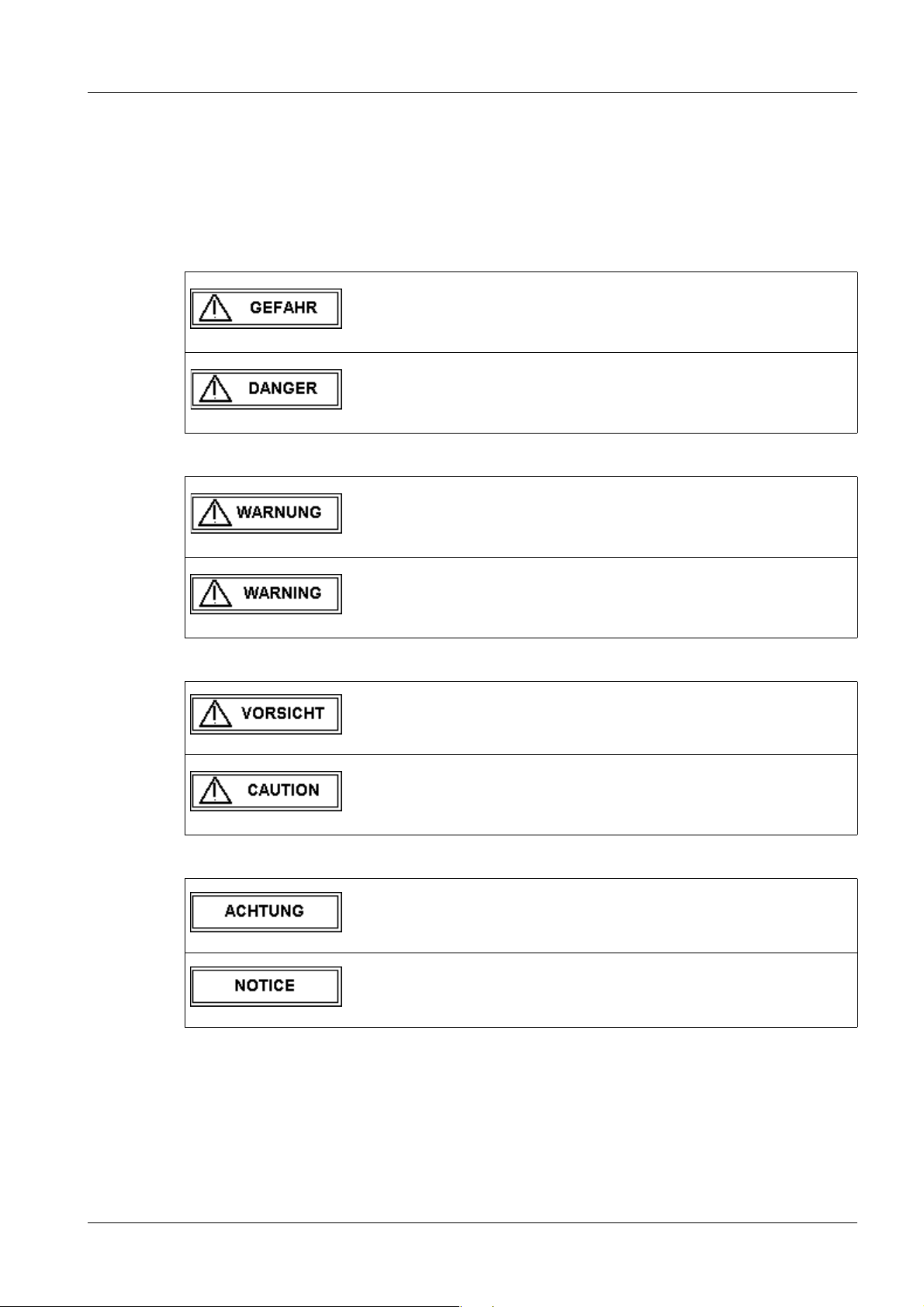
The signal words are used and classified in anticipation of the new Medical Solutions CS
standard which is based on ANSI standard Z535.4.
Emphasized text in this technical documentation has the following meanings:
Tab. 1 GEFAHR / DANGER
Bei einer unmittelbar drohenden Gefahr, die bei Nichtvermeidung
zum Tod oder zu einer schweren Körperverletzung führt.
Indicates when there is an immediate danger that leads to death
or serious physical injury.
Tab. 2 WARNUNG / WARNING
Bei einer Gefahr, die bei Nichtvermeidung zum Tod oder zu einer
schweren Körperverletzung führen kann.
Indicates a risk of danger that may lead to death or serious physical injury.
Tab. 3 VORSICHT / CAUTION
Tab. 4 ACHTUNG / NOTICE
Bei einer Gefahr, die bei Nichtvermeidung zu einer leichten oder
mittleren Körperverletzung und/ oder zu einer Sachbeschädigung führt oder führen kann.
Indicates a risk of danger that leads to slight or moderate physical injury and/or damage to property.
Bei einer Gefahr, die bei Nichtvermeidung zu einem unerwünschten Ergebnis oder Zustand führt oder führen kann (nicht Tod ,
Körperverletzung oder Sachbeschädigung).
Indicates a risk of danger that if disregarded leads or may lead to
a potential situation which may result in an undesirable result or
state (not death, physical injury or property damage).
Siemens SPR2-330.820.30.02.02 ARCADIS Avantic
Medical Solutions
02.08 CS PS SP
Page 5 of 56
Page 6

6 Introduction
Tab. 5 HINWEIS / NOTE
Ist als Tipp zu verstehen. Der Anwender muss diese Anweisung
nicht unbedingt beachten. Er erfährt jedoch Vorteile, wenn er
dies tut.
Should be understood as a tip. The user does not absolutely
have to observe these instructions. However, there will be advantages if he does.
ARCADIS Avantic SPR2-330.820.30.02.02 Siemens
02.08 CS PS SP
Page 6 of 56
Medical Solutions
Page 7

Introduction 7
General safety information (in existing documents) 1.1
WARNING
Danger of injury, death, or material damage.
Non-compliance can lead to death, injury, or material damage.
Please note:
¹ The product-specific safety information in the start-up
instructions and system service documentation,
¹ The general safety information in TD00-000.860.01,
and
¹ The safety information in accordance with ARTD Part
2.
Siemens SPR2-330.820.30.02.02 ARCADIS Avantic
Medical Solutions
02.08 CS PS SP
Page 7 of 56
Page 8

8 Introduction
System identification 1.2
Material no.: ___________________ Serial no.: ________________________
Customer/clinic: ____________________________________________________
Address: _____________________ City: ____________________________
State/province: ________________________ Country:
____________________________
Phone no.: ___________________ Contact person: _____________________
System no.: ___________________ Office: ______________________________
Responsible system engineer: _______________________________________
Image quality acceptance in the factory performed completely and documented by:
Name (block letters):
Signature:
Customer installation date: _______________
IQ quick test performed at:
Handover to customer ❐ During maintenance ❐
Settings deviating from the standard based on:
Country-specific Regulations
Reason: _________________________________________________________
____________________________________________________________________
Name (block letters): __________________ Office:______________
__________________
__________________
❐ Spec. customer wishes ❐
Dept:
Date:
__________________
__________________
Signature: __________________
ARCADIS Avantic SPR2-330.820.30.02.02 Siemens
02.08 CS PS SP
Page 8 of 56
Medical Solutions
Page 9

Introduction 9
Required measuring equipment and tools 1.3
• Set of X-ray filters, 10 x 0.3 mm Cu 44 06 120 RV090
• Precision X-ray filter, 2.1 mm Cu 99 00 598 XE999
• 25 mm AL measuring stand, type 26765 acc. to DIN 6868
Part 50
or
1.2 mm Cu from the X-ray filter set
17 µm Cu strips
97 98 596 G5321 and
11 67 662 G5247
• Resolution test set type 41 28 71 820 RE999
• Densitometer e.g. X-Rite 331 97 02 416 Y1996
or PTW-BC21 including black
check
Type 5321 and light box type
53213
• Dynamic test case 37 90 156 X1963
or 97 50 001 X1963
containing: TV dynamic test 37 90 164 X1963
Heart contour diaphragm 37 90 172 X1963
Capillary test 37 90 180 X1963
Mount 87 13 901 X1963
Veiling glare
test
87 09 743 X1963
• SMfit Spotmeter 77 52 848
Siemens SPR2-330.820.30.02.02 ARCADIS Avantic
Medical Solutions
02.08 CS PS SP
Page 9 of 56
Page 10

10 Introduction
Requirements 1.4
Basic measuring conditions 0
• Completely functioning system; ensure that
- the grid is attached to the I.I. input.
- the cover is attached to the POWERPHOS over the tube collimator.
• A "mid" level fluoro dose rate means: (full format; setting tolerance 10%).
33 cm I.I.: 0,131 µGy/s - fluoro (at the I.I.
input), grid factor 1.5 must be
used.
• A "high" level fluoro dose rate means: (full format; setting tolerance 10%).
33 cm I.I.: 0,262 µGy/s - fluoro (at the I.I.
input), grid factor 1.5 must be
used.
• In addition, dose multipliers predefined in the unit are used for the different operating
modes.
• The setpoints listed in the following chapters apply for a "mid" or "high" dose level; in the
case of deviating settings, setpoints may have to be adapted.
• When requested to switch
- Noise reduction K-factor
- Edge
- Motion detection
- Fluoroscopic characteristic
- or other parameters in the organ programs, select or change a correspondingly predefined organ program or, if possible, change the parameter directly in the acquisition task card.
• The "Service_X_..." exam sets in "General, All Body Region" must be activated in the
ExamSet Editor prior to starting work and returned to the hidden pool after completion
of the work. See the following paragraph "Loading/unloading the exam sets relevant for
the IQ test."
ARCADIS Avantic SPR2-330.820.30.02.02 Siemens
02.08 CS PS SP
Page 10 of 56
Medical Solutions
Page 11

Introduction 11
Activating, deactivating, and selecting the exam sets relevant for the IQ test 0
NOTE
Exam sets relevant for the IQ test have been predefined to
simplify image quality testing and can be loaded.
During normal operation, these are not active and are not
visible to the customer.
The exam sets relevant for the IQ test must be activated
prior to conducting the image quality test.
These exam sets must then be deactivated after completion
of the IQ test.
Activating the exam sets relevant for the IQ test
• Select the "Options" - "Configuration" menu after system start-up.
¹ The "syngo configuration panel" window is displayed.
• Double-click on the "Examination set configuration" icon.
¹ The "Examination set configuration" window is displayed.
• Select the "General" task card in the "Examination set configuration" window.
NOTE
For the exam sets relevant for the IQ test to be visible, no
patient region may be selected in the graphic, virtual patient
anatomy representation.
If a patient region is selected and is displayed lighter than its
surroundings, click once in the gray field to the left or right
outside of the image.
This deselects the previously selected patient region so it is
no longer displayed lighter than its surroundings.
• All available exam sets are displayed in the "Examination set pool" field in the "Exami-
nation set configuration" window.
¹ Already active exam sets have a light background.
¹ Inactive exam sets have a gray background.
• Select each exam set beginning with "SERVICE_....." and copy it to the "Active exami-
nation sets" field by clicking on the button with the down arrow.
¹ All exam sets beginning with "SERVICE_..." are displayed in the "Active examina-
tion sets" field.
• Click on the "Apply" button.
• Click on the "OK" button.
¹ The "Examination set configuration" window closes.
¹ The exam sets relevant for the IQ test can be selected in the examination task
card after a patient is opened under "General."
Siemens SPR2-330.820.30.02.02 ARCADIS Avantic
Medical Solutions
02.08 CS PS SP
Page 11 of 56
Page 12

12 Introduction
Deactivating the exam sets relevant for the IQ test
• Select the "Options" - "Configuration" menu after system start-up.
¹ The "syngo configuration panel" window is displayed.
• Double-click on the "Examination set configuration" icon.
¹ The "Examination set configuration" window is displayed.
• Select the "General" task card in the "Examination set configuration" window.
NOTE
For the exam sets relevant for the IQ test to be visible, no
patient region may be selected in the graphic, virtual patient
anatomy representation.
If a patient region is selected and is displayed lighter than its
surroundings, click once in the gray field to the left or right
outside of the image.
This deselects the previously selected patient region so it is
no longer displayed lighter than its surroundings.
• All available exam sets are displayed in the "Active examination sets" field in the
"Examination set configuration" window. Active exam sets have a light background.
• Select each exam set beginning with "SERVICE_....." and remove them from the
"Active examination sets" field by clicking on the button with the up arrow.
¹ None of the exam sets beginning with "SERVICE_..." are displayed any longer in
the "Active examination sets" field.
• Click on the "Apply" button.
• Click on the "OK" button.
¹ The "Examination set configuration" window closes.
¹ The exam sets relevant for the IQ test are no longer available in the examination
task card after a patient is opened under "General."
Selecting the exam sets relevant for the IQ test in the examination task card
• After system start-up, perform a patient registration for the IQ test.
• After loading, the exam sets relevant for the IQ test can be selected in the examination
task card.
• Select "General" in the list field above the graphic, virtual patient anatomy representa-
tion.
• The exam sets relevant for the IQ test (beginning with "SERVICE_....") can then be
selected in the list field below the graphic, virtual patient anatomy representation.
Loading the ASPIA test images relevant for the IQ test 0
NOTE
ARCADIS Avantic SPR2-330.820.30.02.02 Siemens
02.08 CS PS SP
The ASPIA test images relevant for the IQ test are not selectable during normal system operation.
To load the images, the local service must be open.
Page 12 of 56
Medical Solutions
Page 13

Introduction 13
• Select local service on the system (menu: "Options" - "Service" - "Local service") and
enter the password.
• Leave the local service open during use of the necessary test images.
• Open the patient browser.
¹ The available test images are saved and retrievable under the following path:
"Patient" - "Patient list" - "Local database" - "Service patient" - "Test images."
• If the test images are no longer needed, close the open test images and terminate the
local service.
Siemens SPR2-330.820.30.02.02 ARCADIS Avantic
Medical Solutions
02.08 CS PS SP
Page 13 of 56
Page 14
14 Introduction
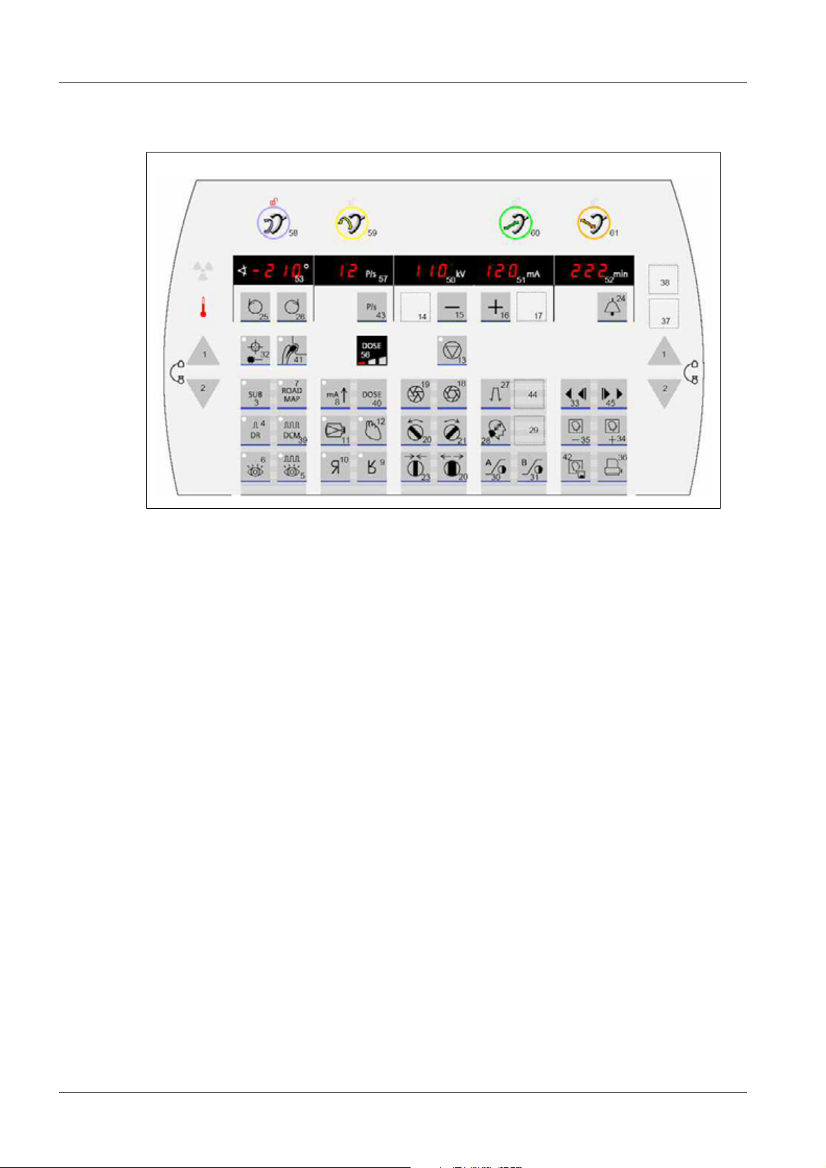
Avantic tableside control (overview) 1.5
Fig. 1: Overview of button assignment on the control panel
Control panel buttons:
ARCADIS Avantic SPR2-330.820.30.02.02 Siemens
02.08 CS PS SP
Page 14 of 56
Medical Solutions
Page 15

Introduction 15
Key no. Function
1 Move each column up two times
2 Move each column down two times
3 Subtraction mode "SUB"
4 Digital radiography mode "DR"
5 Pulsed fluoroscopy mode "pulsed FLUORO"
6 Fluoroscopy mode "FLUORO"
7 Roadmap mode
8 Push button
9 Image rotation top/bottom (vertical)
10 Image rotation left/right (horizontal)
11 Image intensifier zoom
12 Noise reduction (K-factor selection)
13 kV - Control stop
14 Reserve 1
15 kV/mA adjustment (-)
16 kV/mA adjustment (+)
17 Reserve 2
18 Open X iris diaphragm
19 Close X iris diaphragm
20 Rotate filter diaphragms CCW
21 Rotate filter diaphragms CW
22 Open filter diaphragm
23 Close filter diaphragm
24 Reset fluoro buzzer; set fluoro clock to zero
25 Image cursor left
26 Image cursor right
27 Edge enhancement
28 Electronic zoom in the memory
29 Reserve 3
30 Look-up table for Monitor A
31 Look-up table for Monitor B
Siemens SPR2-330.820.30.02.02 ARCADIS Avantic
Medical Solutions
02.08 CS PS SP
Page 15 of 56
Page 16

16 Introduction
32 Laser
33 Scene backward/stop
34 Scroll forward in the image memory
35 Scroll backward in the image memory
36 Initiate the documentation unit
37 n/a
38 n/a
39 DCM mode
40 Dose button
41 Metal button
42 Saving an image
43 Pulses per second
44 Reserve 4
45 Scene forward/stop
Brake control buttons
No. Function
58 Orbital C-arm brake
59 Angular C-arm brake
60 Horizontal C-arm brake
61 Swivel C-arm brake
ARCADIS Avantic SPR2-330.820.30.02.02 Siemens
02.08 CS PS SP
Page 16 of 56
Medical Solutions
Page 17

Monitors 17
Monitors present 0
2- 2Monitors
• Mark the monitor (color or monochrome monitor) present.
• Enter the monitor model and manufacturer in the "Model / Manufacturer" field as indi-
cated on the model plate.
Color monitors ❐ present 0
Model / manufacturer ................../ ..................
Monochrome monitors ❐ present 0
Model / manufacturer ................../ ..................
Siemens SPR2-330.820.30.02.02 ARCADIS Avantic
Medical Solutions
02.08 CS PS SP
Page 17 of 56
Page 18

18 Monitors
Monitor brightness 2.1
• Open local service so that the service patient is displayed in the Patient Browser.
• Load the SMPTE calibration test image.
• Measure the 100% bright field with the SMfit spotmeter.
NOTE
Do not exert any pressure on the LCD display of the monitor
during the measurement with the SMfit spotmeter.
• Switch off the ambient light sensor, if present.
Color monitors 0
Factory
Luminance setpoint:
Left monitor
100% bright
field
Right monitor
100% bright
field
*1 Tolerance specifications in the delivery state.
The monitor is worn out when the maximum adjustable luminance has fallen below 120 cd/m2.
200 cd/m2
+/- 20 cd/m2 *1 .................... cd/m2 .................... cd/m2
200 cd/m2
+/- 20 cd/m2 *1 .................... cd/m2 .................... cd/m2
Measured luminance:
Place of use
Measured luminance:
Remarks: .........................................................................................................................................
Monochrome monitors 0
Factory
Luminance setpoint:
Left monitor
100% bright
field
Right monitor
100% bright
field
*1 Tolerance specifications in the delivery state.
The monitor is worn out when the maximum adjustable luminance has fallen below 350 cd/m2.
Remarks: .........................................................................................................................................
400 cd/m2
+/- 20 cd/m2 *1
400 cd/m2
+/- 20 cd/m2 *1
Measured luminance:
.................... cd/m2 .................... cd/m2
.................... cd/m2 .................... cd/m2
Place of use
Measured luminance:
ARCADIS Avantic SPR2-330.820.30.02.02 Siemens
02.08 CS PS SP
Page 18 of 56
Medical Solutions
Page 19

Monitors 19
Monitor contrast 2.2
• Load the SMPTE calibration test image.
• Switch off the ambient light sensor of the monitor, if present.
• Measure the 0% dark field with the SMfit spotmeter.
NOTE
Do not exert any pressure on the LCD display of the monitor
during the measurement with the SMfit spotmeter.
• Use the luminance measured previously in the "Monitor brightness" section in the 100%
bright field to calculate the contrast.
• Calculate the contrast as follows and enter it in the table:
Monitor, measured luminance in 100% bright field
Contrast =
_______________(divided by)_______________
Monitor, measured luminance in 0% dark field
Color monitors 0
Setpoints Factory Place of use
Left monitor
0% dark field
Luminance setpoint:
≤ 1 cd/m2
Measured luminance:
.................... cd/m2
Measured luminance:
.................... cd/m2
Left monitor
Contrast
Right monitor
0% dark field
Right monitor
Contrast
Contrast setpoint:
≥ 200
Luminance setpoint:
≤ 1 cd/m2
Contrast setpoint:
≥ 200
Calculated contrast:
....................
Measured luminance:
.................... cd/m2
Calculated contrast:
....................
Calculated contrast:
....................
Measured luminance:
.................... cd/m2
Calculated contrast:
....................
Siemens SPR2-330.820.30.02.02 ARCADIS Avantic
Medical Solutions
02.08 CS PS SP
Page 19 of 56
Page 20

20 Monitors
Monochrome monitors 0
Setpoints Factory Place of use
Left monitor
0% dark field
Left monitor
Contrast
Right monitor
0% dark field
Right monitor
Contrast
Luminance setpoint:
≤ 1 cd/m2
Contrast setpoint:
≥ 350
Luminance setpoint:
≤ 1 cd/m2
Contrast setpoint:
≥ 350
Measured luminance:
.................... cd/m2
Calculated contrast:
....................
Measured luminance:
.................... cd/m2
Calculated contrast:
....................
Measured luminance:
.................... cd/m2
Calculated contrast:
....................
Measured luminance:
.................... cd/m2
Calculated contrast:
....................
Visual evaluation of the SMPTE calibration test image 0
• Display the SMPTE calibration test image on both monitors.
• Visually evaluate the SMPTE calibration test image on both monitors.
Factory Left monitor Right monitor
All gray values are clearly visible: ❐ Yes / ❐ No ❐ Yes / ❐ No
The 5% field and the 95% field are visible: ❐ Yes / ❐ No ❐ Yes / ❐ No
Place of use Left monitor Right monitor
All gray values are clearly visible: ❐ Yes / ❐ No ❐ Yes / ❐ No
The 5% field and the 95% field are visible: ❐ Yes / ❐ No ❐ Yes / ❐ No
ARCADIS Avantic SPR2-330.820.30.02.02 Siemens
02.08 CS PS SP
Page 20 of 56
Medical Solutions
Page 21

Monitors 21
Fig. 2: SMPTE calibration test image
Pos. 1 0% field
Pos. 2 5% field
Pos. 3 95% field
Pos. 4 100% field
Close local service.
• Close Local Service again, otherwise the measurement field is displayed and, as a
result, influences the image for the subsequent checks.
Siemens SPR2-330.820.30.02.02 ARCADIS Avantic
Medical Solutions
02.08 CS PS SP
Page 21 of 56
Page 22

22 Checking the ADR control characteristics
Requirements 0
3- 3Checking the ADR control characteristics
• The indicated exam sets must be selected for fluoroscopy, pulsed fluoroscopy, DCM,
and DR. See the "Loading the exam sets relevant for the IQ test" section.
• Attach a 2.1 mm Cu precision X-ray filter for prefiltering in the area of the radiation exit.
• All exposures are pre-contrast images (no additional object in the beam path).
Evaluation 0
NOTE
The specified exam sets must be used for the checks.
The activation of the exam sets is described in the introduction chapter.
ARCADIS Avantic SPR2-330.820.30.02.02 Siemens
02.08 CS PS SP
Page 22 of 56
Medical Solutions
Page 23

Checking the ADR control characteristics 23
ADR control curve for the fluoroscopy mode 3.1
• Select fluoro.
• Select I.I. full format.
• Select the "General, All region, SERVICE_Q_S2" exam set.
• Select medium dose level.
X
X
• Radiation on.
• Read off the kV and mA values displayed on the operating panel.
• Radiation off.
• Record the values in Tab. 1, Line S2.
• Fluoro and I.I. full format remain selected.
• Select the "General, All region, SERVICE_Q_C_HC2" exam set.
• Select medium dose level.
• Radiation on.
• Read off the kV and mA values displayed on the operating panel.
• Radiation off.
• Record the values in Tab. 1, Line HC2.
• The actual values documented at the factory must be obtained again at the place of
use. Admissible deviations: Tube voltage (kV) ± 1 kV, tube current (mA) ± 10%.
Tab. 6
Cont. fluoro
ADR control curves (included in
the exam set)
Setpoints Actual values
Factory Place of use
kV mA kV mA kV mA
S2
(General, All region,
SERVICE_Q_S2, Mid Dose)
HC 2
(General, All region,
SERVICE_Q_C_HC2, Mid Dose)
66 - 72 1,0 - 1,2
62 - 64 2,5 - 3,7
Siemens SPR2-330.820.30.02.02 ARCADIS Avantic
Medical Solutions
02.08 CS PS SP
Page 23 of 56
Page 24

24 Checking the ADR control characteristics
ADR control curves for the pulsed fluoroscopy mode 3.2
• Select pulsed fluoro.
• Select I.I. full format.
• Select the "General, All region, SERVICE_Q_S2" exam set.
• Select medium dose level.
• Pulse frequency 8 (7.5) pulses per second
X
X
• Radiation on.
• Read off the kV and mA values displayed on the monitor.
• Radiation off.
• Record the values in Tab. 2, Line S2/8 Fps.
• Pulsed fluoro and I.I. full format remain selected.
• Select the "General, All region, SERVICE_Q_C_HC2" exam set.
• Select medium dose level.
• Radiation on.
• Read off the kV and mA values displayed on the monitor.
• Radiation off.
• Record the values in Tab. 2, Line HC2/8 Fps.
• The actual values documented at the factory must be obtained again at the place of
use. Admissible deviations: Tube voltage (kV) ± 1 kV, tube current (mA) ± 10%.
Ta b . 7
Pulsed fluoro
ADR control curves
(included in the exam set)
Setpoints Actual values
Factory Place of use
kV mA kV mA kV mA
S2/8 Fps
(General, All region,
SERVICE_Q_S2, Mid Dose)
HC2/8 Fps
(General, All region,
SERVICE_Q_C_HC2, Mid
Dose)
ARCADIS Avantic SPR2-330.820.30.02.02 Siemens
02.08 CS PS SP
64 - 70 14,3 - 18,6
60 - 63 36,0 - 56,3
Page 24 of 56
Medical Solutions
Page 25

Checking the ADR control characteristics 25
ADR control curve for the DCM mode 3.3
X
DCM option present:
If no: The "ADR control curve for the DCM mode" section does not
apply.
Ye s No
• Select DCM.
• Select I.I. full format.
• Select the "General, All region, SERVICE_Res_HC2" exam set.
• Pulse frequency 8 (7.5) pulses per second
• Select high dose level.
• Radiation on.
• Read off the kV and mA values displayed on the monitor.
• Radiation off.
• Record the values in Tab. 2, Line HC2/8 Fps.
• The actual values documented at the factory must be obtained again at the place of
use. Admissible deviations: Tube voltage (kV) ± 1 kV, tube current (mA) ± 10%.
Tab. 8
DCM
Setpoints Actual values
ADR control curve
(included in the exam set)
HC2/8 Fps
(General, All region,
SERVICE_Q_C_HC2, High
Dose)
Factory Place of use
kV mA kV mA kV mA
65 - 69 173 - 250
Siemens SPR2-330.820.30.02.02 ARCADIS Avantic
Medical Solutions
02.08 CS PS SP
Page 25 of 56
Page 26

26 Checking the ADR control characteristics
ADR control curves for the DR mode 3.4
• Select DR.
• Select I.I. full format.
• Select the "General, All region, SERVICE_Q_C_HC2" exam set.
• Select medium dose level.
X
• Radiation on.
• Read off the kV and mAs values displayed on the monitor.
• Radiation off.
• Record the values in Tab. 3, Line DR 1000W.
• The actual values documented at the factory must be obtained again at the place of
use. Admissible deviations: Tube voltage (kV) ± 1 kV, Tube current (mA) ± 10%.
Ta b . 9
DR takeover Setpoints Actual values
Factory Place of use
kV mAs kV mAs kV mAs
DR 1000W
K=16
(General, All region,
SERVICE_Q_C_HC2, Mid
Dose)
62 - 65 4,2 - 6,8
ARCADIS Avantic SPR2-330.820.30.02.02 Siemens
02.08 CS PS SP
Page 26 of 56
Medical Solutions
Page 27

Checking the image position 27
Checking the image position 0
4- 4Checking the image position
Requirements 0
Place a long, thin, straight object (e.g. wire solder bent straight) near the I.I. -- at an exact
right angle to the C-arm orientation.
Place a second object next to it -- for direction determination (see (Fig.3/p.27)).
Fig. 3: Image position
Pos. 1 C_arm_alignment
The rotation angle of the image on the display of the basic unit must be 0.
If necessary, set the angle to 0.
X Record an image (see (Fig.4/p.28)).
Siemens SPR2-330.820.30.02.02 ARCADIS Avantic
Medical Solutions
02.08 CS PS SP
Page 27 of 56
Page 28

28 Checking the image position
Fig. 4: Results image
Evaluation 0
The object must appear on the screen in an exactly horizontal position.
Factory Place of use
Image position OK? ❐ Ye s ❐ No ❐ Ye s ❐ No
ARCADIS Avantic SPR2-330.820.30.02.02 Siemens
02.08 CS PS SP
Page 28 of 56
Medical Solutions
Page 29

Resolution 29
Checking the resolution and minimum contrast 0
5- 5Resolution
Requirements 0
• Use resolution test type 41 (factory and place of use).
• Attach the resolution test directly to the I.I. grid in the center of the I.I. at an angle of
approx. 90 degrees with respect to the grid lines (45 degrees with respect to the CCD
structure).
• In the factory: Place a 25 mm AL measuring stand on the I.I.
• Place of use: If the 25 mm AL measuring stand (with 0.4 mm recess) is present, attach it
near the I.I., otherwise attach the 17 µm Cu strip directly to the I.I. grid next to the resolution test. Additionally, place a 1.2 mm Cu filter in the beam path. Fading at the I.I. edge
can be eliminated via collimation.
• Select the indicated operating mode (fluoro/DCM/DR (1000W)) and the respective I.I.
format according to the "Resolution" table.
• Additionally, select the indicated exam set after selecting the appropriate operating
mode (fluoro/DCM/DR (1000W)).
X
• Radiation on.
• Show the resolution test phantom.
• Set the monitor contrast to optimum resolution.
• Set the edge enhancement to optimum resolution.
• Radiation OFF.
Siemens SPR2-330.820.30.02.02 ARCADIS Avantic
Medical Solutions
02.08 CS PS SP
Page 29 of 56
Page 30

30 Resolution
Evaluation of resolution and minimum contrast 0
DCM option present:
Ye s No
If no: Checking the resolution and minimum contrast during DCM
mode does not apply.
• Determine the resolution of the LIH image and enter it in the Resolution table.
NOTE
Tab. 10 Resolution
Operating mode
(Exam set)
DL (HC2)
(General, All region,
SERVICE_Q_C_HC2, Mid
Dose)
Use the electronic zoom function and windowing in the Viewing task card if necessary.
I.I. for-
mat
I.I. 33 setpoints
for resolution
Actual resolution values
[LP/mm]
Factory
Full for-
mat
≥ 1.4 LP/mm
Place of
use
DL (HC2)
(General, All region,
SERVICE_Q_C_HC2, Mid
Dose)
DL (HC2)
(General, All region,
SERVICE_Q_C_HC2, Mid
Dose)
DL (HC2)
(General, All region,
SERVICE_Q_C_HC2, Mid
Dose)
DCM (HC2)
(General, All region,
SERVICE_Q_C_HC2, Mid
Dose)
DCM (HC2)
(General, All region,
SERVICE_Q_C_HC2, Mid
Dose)
Zoom 1 ≥ 1.8 LP/mm
Zoom 2 ≥ 2.2 LP/mm
Zoom 3 ≥ 2.5 LP/mm
Full for-
mat
≥ 1.2 LP/mm
Zoom 1 ≥ 1.6 LP/mm
ARCADIS Avantic SPR2-330.820.30.02.02 Siemens
02.08 CS PS SP
Page 30 of 56
Medical Solutions
Page 31

Resolution 31
Operating mode
(Exam set)
DCM (HC2)
(General, All region,
SERVICE_Q_C_HC2, Mid
Dose)
DCM (HC2)
(General, All region,
SERVICE_Q_C_HC2, Mid
Dose)
DR (1000W)
(General, All region,
SERVICE_Q_C_HC2, Mid
Dose)
DR (1000W)
(General, All region,
SERVICE_Q_C_HC2, Mid
Dose)
I.I. for-
mat
I.I. 33 setpoints
for resolution
Zoom 2 ≥ 2.0 LP/mm
Zoom 3 ≥ 2.2 LP/mm
Full for-
mat
≥ 1.4 LP/mm
Zoom 1 ≥ 1.8 LP/mm
Actual resolution values
[LP/mm]
Factory
Place of
use
DR (1000W)
(General, All region,
Zoom 2 ≥ 2.2 LP/mm
SERVICE_Q_C_HC2, Mid
Dose)
DR (1000W)
(General, All region,
Zoom 3 ≥ 2.5 LP/mm
SERVICE_Q_C_HC2, Mid
Dose)
• Also check the minimum contrast during the resolution test and enter it in the minimum
contrast table.
Is the minimum contrast visible?
Tab. 11 Minimum contrast
Factory Place of use
Full format
Ye s N o
Zoom 1
Ye s N o
Full format
Ye s N o
Zoom 1
Ye s N o
Siemens SPR2-330.820.30.02.02 ARCADIS Avantic
Medical Solutions
02.08 CS PS SP
Page 31 of 56
Page 32

32 Resolution
Zoom 2
Ye s N o
Zoom 3
Ye s N o
Zoom 2
Ye s N o
Zoom 3
Ye s N o
Evaluation of resolution without prefiltering 0
• Subsequently remove the 25 mm Al or 1.2 mm Cu prefilter.
• Collimate to the resolution test.
• Perform the resolution test for DR again without prefilter as above.
Tab. 12 Evaluation of resolution without prefiltering
Operating mode I.I. format Setpoints
Resolution
Factory Place of
Actual value
Resolution [LP/mm]
use
DR (1000W)
(General, All region,
SERVICE_Q_C_HC2, Mid
Dose)
DR (1000W)
(General, All region,
SERVICE_Q_C_HC2, Mid
Dose)
DR (1000W)
(General, All region,
SERVICE_Q_C_HC2, Mid
Dose)
DR (1000W)
(General, All region,
SERVICE_Q_C_HC2, Mid
Dose)
23 cm I.I. Monitor 1 Monitor 1
Full for-
mat
Zoom 1 ≥ 2.0 LP/mm
Zoom 2 ≥ 2.5 LP/mm
Zoom 3 ≥ 3.1 LP/mm
≥ 1.6 LP/mm
ARCADIS Avantic SPR2-330.820.30.02.02 Siemens
02.08 CS PS SP
Page 32 of 56
Medical Solutions
Page 33

Capillary test 33
Dynamic Test 0
6- 6Capillary test
SUBTRACTION option present:
If no:
The sections Capillary visibility test during subtraction, Capillary visibility test for roadmap, and Pixelshift function do not apply.
NOTE
The dynamic test in conjunction with the plexi capillary test
is used to detect small contrast differences.
Capillary visibility test during fluoroscopy 0
Measurement setup
• Remove the 1.2 mm Cu precision X-ray filter from the beam path.
• Place the dynamic test without holder, with heart contour diaphragm and plexi capillary
test on an X-ray-compatible table. The plexi capillaries are close to the I.I.
Ye s No
X
Requirements
• Select full format.
• Select the "General, All region, SERVICE_Q_C_HC2" exam set.
• Set the dose rate level to "High."
• Set a distance from the I.I. to the dynamic test that allows for the image field to be cov-
ered completely.
• Set noise reduction to high. (The LED in button 11 of the control console (heart button)
does not light up.)
• Set edge enhancement to the lowest level (button: ).
• Select linear LUT (LUT_Linear).
Evaluation of the monitor image
• Switch radiation on and evaluate the live image during irradiation.
• Check off non-visible plexi capillaries in (Fig.5/p.34) (from left to right 2L - 1 - 5R).
Setpoints
¹ The plexi capillaries not identified in (1/Fig.5/p.34) must be visible.
Siemens SPR2-330.820.30.02.02 ARCADIS Avantic
Medical Solutions
02.08 CS PS SP
Page 33 of 56
Page 34

34 Capillary test
Fig. 5: Monitor image
Pos. 1 Target value
Pos. 2 Factory
Pos. 3 Place of use
Pos. 4 Group - 3 mm wide
Pos. 5 Group - 2 mm wide
Pos. 6 Group - 1 mm wide
Capillary visibility test during subtraction 0
Measurement setup
• Place the dynamic test without holder, with heart contour diaphragm and plexi capillary
test on an X-ray-compatible table. The plexi capillaries are close to the I.I.
• Mechanically clamp the plexi capillary test so that the plexi capillaries can be moved by
the rubber ball during the subtraction exposure.
Requirements
• Select full format.
• Select the "General, All region, SERVICE_Q_C_HC2" exam set.
• Set the dose rate level to "High."
• Set a distance from the I.I. to the dynamic test that allows for the image field to be cov-
ered completely.
• Select subtraction.
¹ SUB LUT 3MH is selected (pre-setting).
• Set edge enhancement to the lowest level (button: ).
Trigger subtraction
• Switch radiation on.
X ¹ After 3 seconds of radiation, the mask is set automatically.
• Then cause the plexi capillary test to move by squeezing the rubber ball.
• After another 3 seconds, switch the radiation off.
ARCADIS Avantic SPR2-330.820.30.02.02 Siemens
02.08 CS PS SP
Page 34 of 56
Medical Solutions
Page 35

Capillary test 35
Evaluation of the capillary visibility
• Use the mouse in the scroll bar to scroll back in the viewing task card to where the white
and black capillaries are best visible (2 to 3 images).
NOTE
NOTE
For improved visibility,
SUB LUT 4MH can also be selected as needed.
Do not evaluate the first white line.
Start the evaluation with the first black line.
• Check off non-visible black plexi capillaries in the "Subtraction, black lines" table (from
left to right 2L - 1 - 5R).
• Check off non-visible white plexi capillaries in the "Subtraction, white lines" table (from
left to right 2L - 1 - 5R).
Setpoints
¹ The black plexi capillaries not identified in the "Setpoints" column of the "Sub-
traction, black lines" table must be visible.
¹ The white plexi capillaries not identified in the "Setpoints" column of the "Sub-
traction, white lines" table must be visible.
Tab. 13 Subtraction, black lines
Setpoints Factory Place of use
2L 1 5R 2L 1 5R 2L 1 5R Group
Black To p
Black X
Black XXX
Group
3 mm
Width
Black Middle
Black X
Black XXX
Group
2 mm
Width
Black Bottom
Black X
Black XXX
Group
1 mm
Width
Siemens SPR2-330.820.30.02.02 ARCADIS Avantic
Medical Solutions
02.08 CS PS SP
Page 35 of 56
Page 36

36 Capillary test
Tab. 14 Subtraction, white lines
Setpoints Factory Place of use
2L 1 5R 2L 1 5R 2L 1 5R Group
White To p
White X
White XXX
White Middle
White X
White XXX
White Bottom
White X
White XXX
Evaluation of visual brightness impression
Group
3 mm
Width
Group
2 mm
Width
Group
1 mm
Width
• On monitor A, evaluate the white, 3 mm capillary line in fields 2L, 1 and 5R. There must
not be any noticeable difference in brightness in the fields.
No noticeable difference in brightness Factory Place of use
visible in fields 2L, 1 and 5R: Yes No
Ye s
No
Capillary visibility test for roadmap 0
Measurement setup
• Place the dynamic test without holder, with heart contour diaphragm and plexi capillary
test on an X-ray-compatible table. The plexi capillaries are close to the I.I.
• Mechanically clamp the plexi capillary test so that the plexi capillaries can be moved by
the rubber ball during the subtraction exposure.
Requirements
• Select full format.
• Select the "General, All region, SERVICE_Q_C_HC2" exam set.
• Set the dose rate level to "Mid."
ARCADIS Avantic SPR2-330.820.30.02.02 Siemens
02.08 CS PS SP
Page 36 of 56
Medical Solutions
Page 37

Capillary test 37
• Set a distance from the I.I. to the dynamic test that allows for the image field to be cov-
ered completely.
• Select roadmap.
¹ SUB LUT 3MH is selected (pre-setting).
• Set edge enhancement to the lowest level (button: ).
Start roadmap
• Switch radiation on (phase A).
X ¹ After 3 seconds of radiation, the mask is set automatically (phase B).
¹ Do not move the plexi capillary test (rubber ball).
• After another 3 seconds, switch the radiation off.
• Switch radiation on again (phase C).
X ¹ The LUT must have switched over to LUT Road 3 (pre-setting). If SUB LUT 3MH
has correctly switched over to LUT Road 3, the image background changes from
light to dark.
• Move the plexi capillary test by squeezing the rubber ball.
• Radiation remains switched on during the evaluation.
Evaluation of the capillary visibility
• Radiation remains switched on during the evaluation.
NOTE
Do not evaluate the first white line.
Start the evaluation with the first black line.
• Check off non-visible black plexi capillaries in the "Roadmap, black lines" table (from
left to right 2L - 1 - 5R).
• Check off non-visible white plexi capillaries in the "Roadmap, white lines" table (from
left to right 2L - 1 - 5R).
• After the capillary visibility is evaluated, switch radiation off.
Setpoints
¹ The black plexi capillaries not identified in the "Setpoints" column of the "Road-
map, black lines" table must be visible.
¹ The white plexi capillaries not identified in the "Setpoints" column of the "Road-
map, white lines" table must be visible.
Siemens SPR2-330.820.30.02.02 ARCADIS Avantic
Medical Solutions
02.08 CS PS SP
Page 37 of 56
Page 38

38 Capillary test
Tab. 15 Roadmap, black lines
Setpoints Factory Place of use
2L 1 5R 2L 1 5R 2L 1 5R Group
Black To p
Black X
Black XXX
Group
3 mm
Width
Black Middle
Black X
Black XXX
Group
2 mm
Width
Black Bottom
Black X
Black XXX
Group
1 mm
Width
Tab. 16 Roadmap, white lines
Setpoints Factory Place of use
2L 1 5R 2L 1 5R 2L 1 5R Group
White To p
White X
White XXX
Group
3 mm
Width
White Middle
White X
White XXX
Group
2 mm
Width
White Bottom
White X
White XXX
Group
1 mm
Width
ARCADIS Avantic SPR2-330.820.30.02.02 Siemens
02.08 CS PS SP
Page 38 of 56
Medical Solutions
Page 39

Capillary test 39
Evaluation of LUT change from phase B to phase C
• As described in the "Start roadmap" section, LUT Road 3 must automatically be
selected when changing to phase C.
Factory Place of use
LUT changed when changing from phase B to
phase C:
Ye s No
Ye s
No
Pixelshift function 0
Requirements
The subtraction image from the roadmap test is present.
• Select the roadmap image in the Viewer.
• Select pixelshift in the SUB task card.
Evaluation
• Using the arrow tool, move the mask successively in all directions:
¹ Apart from the black and white edge strips, no artifacts may occur.
• Using the Auto Pixelshift tool, select a location.
¹ In this location the shifted mask must return to artifact-free superimposition.
Factory Place of use
Pixelshift function OK? ❐ Ye s ❐ No ❐ Yes ❐ No
Siemens SPR2-330.820.30.02.02 ARCADIS Avantic
Medical Solutions
02.08 CS PS SP
Page 39 of 56
Page 40

40 Contrast
Edge enhancement, contrast enhancement, and object move-
7- 7Contrast
ments
NOTE
Edge enhancement 0
Requirements
• Place the dynamic test without holder, with heart contour diaphragm and plexi capillary
test, on the I.I. input screen. The plexi capillaries are close to the I.I.
• Select the "General, All region, SERVICE_Q_C_HC2" exam set.
• Select medium dose level.
• Set edge enhancement to the lowest level.
X
• Release fluoroscopy briefly.
¹ Use the LIH image to evaluate the edge enhancement.
Only perform edge enhancement, LUT selection change, and
motion unsharpness at the factory.
0
Evaluation of the monitor image
• Activate the button for selecting edge enhancement on the control console several
times.
¹ The individual edge enhancement levels (20%, 40%, ...) are selected one after
another.
• Evaluate the edge enhancement function.
Factory
Function control of edge enhancement OK?
=> The bright-dark transitions are clearly visible when a higher
percentage edge enhancement level is selected.
❐
Ye s
❐
No
LUT selection change 0
Requirements
• Place the dynamic test without holder, with heart contour diaphragm and plexi capillary
test, on the I.I. input screen. The plexi capillaries are close to the I.I.
• Select the "General, All region, SERVICE_Q_C_HC2" exam set.
• Select medium dose level.
• Set edge enhancement to the lowest level.
ARCADIS Avantic SPR2-330.820.30.02.02 Siemens
02.08 CS PS SP
Page 40 of 56
Medical Solutions
Page 41

Contrast 41
X • Release fluoroscopy briefly.
¹ Use the LIH image to evaluate the LUT selection change.
Evaluation of the monitor image
• Activate the LUT selection change button.
¹ The image contrast changes.
• Evaluate the LUT selection change function.
Factory
LUT selection change function in order? ❐ Ye s ❐ No
Motion unsharpness 0
DCM option present:
If no: Motion unsharpness section does not apply.
Requirements
Ye s No
• Remove the dynamic test without holder, with heart contour diaphragm and plexi capil-
lary test, from the I.I. input screen and place on a separate surface (e.g. table).
• Additionally, place a screwdriver in the center of the dynamic test.
• Position the C-arm with respect to the separate surface so that the dynamic test is over
or under the I.I. input screen. The plexi capillaries are close to the I.I.
NOTE
If no suitable surface is available, the dynamic test with heart
contour diaphragm and plexi capillary test can also be
placed directly on the I.I. input screen.
An X-ray-absorbing object (e.g. long aluminum rod or the
like) must by moved over the dynamic test in the beam path
during radiation.
Pay attention to radiation protection!
• Select the "General, All region, SERVICE_Q_C_HC2" exam set.
• Select medium dose level.
Evaluation of the monitor image
X
• Fluoroscopy on.
• Move the C-arm horizontally during fluoroscopy.
¹ A smearing effect is clearly visible on the image during movement of the C-arm
with respect to the capillary test.
• Radiation off.
• Select the DCM operating mode.
Siemens SPR2-330.820.30.02.02 ARCADIS Avantic
Medical Solutions
02.08 CS PS SP
Page 41 of 56
Page 42

42 Contrast
• The "General, All region, SERVICE_Q_C_HC2" exam set is selected.
• Select medium dose level.
• Select the maximum pulse frequency.
X
• Radiation (DCM) on.
• Move the C-arm horizontally during DCM.
¹ The object is depicted in sharp focus but in multiple images when the C-arm is
moved with respect to the capillary test.
• Radiation off.
• Evaluate the motion unsharpness test.
• Remove the screwdriver that was placed there before.
Factory
FL, DCM functions OK? ❐ Ye s ❐ No
Comments
_______________________________________________________________________
_______________________________________________________________________
_______________________________________________________________________
_______________________________________________________________________
_______________________________________________________________________
ARCADIS Avantic SPR2-330.820.30.02.02 Siemens
02.08 CS PS SP
Page 42 of 56
Medical Solutions
Page 43

Checking the Controls 43
8- 8Checking the Controls
NOTE
The following controls are active for the specified prefiltering.
Automatic dose rate control (ADR) with approximately 9 to 11 mm Cu and
Automatic TV iris collimator control (AIR) with approximately 11 to 13 mm Cu and
The test is used to test the functioning of these controls.
Requirements
Perform only in the factory.
dynamic test in the beam path
dynamic test in the beam path
• Both monitors must be set to give approximately the same brightness and contrast
impression (synchronism) (LUT, brightness and contrast setting).
Preparations
• Attach the dynamic test without holder and plexi capillary test, but with heart contour
diaphragm, to the I.I.:
• Select the "General, All region, SERVICE_Q_HC2" exam set.
• Select medium dose level.
• Select the fluoro operating mode.
X
X
• Switch the I.I. to full format.
• Completely open the collimator.
• Prefilter with Cu until 120 kV to 124 kV are displayed. To do this, switch on fluoroscopy
briefly (approx. 9 mm to 11 mm Cu necessary).
¹ Automatic dose rate control (ADR) is active.
• Radiation on.
• Select linear contrast LUT. (LUT_Linear)
• Evaluate the brightness of the fluoroscopy image.
• Radiation off.
• Save the LIH image and display it on the reference monitor.
TV iris collimator control
• Additionally, attach 2.1 mm Cu to the radiation exit.
• Radiation on.
¹ Generator limit 125 kV/4.3 mA must be reached.
¹ The automatic TV iris collimator control (AIR) is active.
• Select linear contrast LUT. (LUT_Linear)
• Evaluate the brightness of the fluoroscopy image.
• Radiation off.
• Save the LIH image.
Siemens SPR2-330.820.30.02.02 ARCADIS Avantic
Medical Solutions
02.08 CS PS SP
Page 43 of 56
Page 44

44 Checking the Controls
• Display both images on both monitors.
¹ Display the image saved during active ADR on the right monitor.
¹ Display the image saved during active AIR on the left monitor.
¹ Both images are displayed with the linear LUT (LUT_Linear).
• Evaluate the brightness impression of the fluoroscopic image generated during active
AIR and compare it to that of the reference image generated during active ADR.
¹ The brightness impression should be approximately the same.
Evaluation
Factory
Same brightness impression? Yes No
ARCADIS Avantic SPR2-330.820.30.02.02 Siemens
02.08 CS PS SP
Page 44 of 56
Medical Solutions
Page 45

Digital preprocessing 45
Digital preprocessing 0
9- 9Digital preprocessing
NOTE
Vignetting compensation 0
Requirements
• Attach a 2.1 mm Cu prefilter close to the tube.
• Set the monitor contrast to linear.
Test sequence
• Select the "General, All region, SERVICE_Q_C_HC2" exam set.
• Select medium dose level.
X
• Release fluoroscopy for approx. 10 seconds and save the image using the ATB button.
Perform only in the factory.
Exception: Also perform a check after replacing the image
intensifier.
• Select local service (menu: <Options>-<Service>-<Local Service>).
¹ When the local service window is open and the measurement function is selected
in the Viewing task card, the corresponding brightness value (min/max/mean/SD)
can be displayed by selecting an image region with the mouse.
• Minimize the local service window or move it to the right monitor.
• Select the previously saved image in the viewer.
• In the Tools menu bar of the imaging system, select Measure ---> Rectangle ↵ .
• Select the 5 fields according to the "measuring field" image. To do this, place the mouse
pointer on a corner of the field to be measured and select the field according to the "display values" image while pressing the left mouse button.
¹ The brightness data is displayed for every marked field.
• Read off the average brightness value (mean) for every field.
¹ Divide the average (mean) of each of the fields at the edge by the average (mean)
of the middle field and then multiply each result by 100 (brightness outside to
brightness middle (in %) --> (Mean X / (Mean 1/ 100))).
• Evaluate the vignetting compensation function.
¹ The values calculated should be in the range of 80% to 120%.
Siemens SPR2-330.820.30.02.02 ARCADIS Avantic
Medical Solutions
02.08 CS PS SP
Page 45 of 56
Page 46

46 Digital preprocessing
Evaluation
Fig. 6: VC10A_VignMeas2
Brightness value
Brightness in %
• Evaluate the vignetting compensation function.
Procedure for correcting the setting of the vignetting compensation:
• Log in to Service Software.
• Click on "MainSystem" and "Next."
• Click on "Image Intensifier."
Center
scan field
___________
n.a.
¹ The values calculated should be in the range of 80% to 120%.
¹ Correct the vignetting compensation if necessary.
Left
measurement
field [%]
___________
___________
Right
measurement
field [%]
___________
___________
Upper
measurement
field [%]
___________
___________
Lower
measurement field
[%]
__________
__________
ARCADIS Avantic SPR2-330.820.30.02.02 Siemens
02.08 CS PS SP
Page 46 of 56
Medical Solutions
Page 47

Digital preprocessing 47
• Enter the new value in the "Vignetting" field and confirm with the Enter key.
- Standard vignetting compensation = "2"
- For calculated values "< 80%" increase the value by one step.
- For calculated values "> 120%" decrease the value by one step.
- For a calculated lowest value of "< 80%", measured in one of the outer measurement
fields, but when the simultaneously calculated highest value is ">120%" in another
one of the outer measurement fields, program the vignetting compensation in such a
way that the degree by which the brightness exceeds and falls short of the average
brightness lies more or less symmetrically around 100%.
• Click on "Save" and confirm.
¹ The Main System will automatically be restarted.
• Perform the "Vignetting compensation" test again.
Result
• If the vignetting compensation was adjusted:
¹ Setting modified from: _____ to: _____
Factory or after replacing
I.I.
Vignetting compensation OK? ❐ Ye s ❐ No
Siemens SPR2-330.820.30.02.02 ARCADIS Avantic
Medical Solutions
02.08 CS PS SP
Page 47 of 56
Page 48

48 Image Disturbances
Image Disturbances (artifacts) 0
10- 10Image Disturbances
• Check off all image disturbances found during settings and IQ tests in the table in the IQ
Test Certificate.
• If image disturbances are detected that are not listed in the table, describe them under
"Other disturbances."
• Three assessment numbers indicating the extent of the disturbance are provided for
each assessment of the relevant disturbance.
Definition of the assessment numbers 0
1 = No disturbances and artifacts were detected during startup.
2 = Minor disturbances, artifacts occurred sporadically during startup. The cause
could not be localized and the "error" could not be corrected. The disturbances
scarcely affect the good overall image impression, and the ability to make a
medical diagnosis from the images is not impaired in any way. Therefore, the
artifacts are tolerable.
3 = During start-up, more frequent or stronger disturbances/artifacts occurred that
disturb the overall impression of the image or impair the ability of the images to
be diagnosed medically and are therefore no longer tolerable. The system must
not be shipped or handed over to the operator in this condition.
ARCADIS Avantic SPR2-330.820.30.02.02 Siemens
02.08 CS PS SP
Page 48 of 56
Medical Solutions
Page 49

Image Disturbances 49
Description of the artifacts 10.1
• Hum:
Inconsistencies resulting from electromagnetic interference in the imaging systems are
unattractive and disturbing. Depending on the nature of the disturbance, they can considerably impair the ability of the images to be evaluated and should ideally not occur at
all. They are tolerable only to a very slight degree. Hum disturbances are visible as sporadic, horizontal light-dark patterns in the image; they are temporary and are not limited
to a specific location.
• Streaking:
Very high-frequency electromagnetic radiation is visible in the image as light or dark,
sometimes very short, horizontal lines (temporary). Interference stripes that are caused
by dirt on optically effective surfaces must also be recorded here. They are limited to a
specific location and are not temporary. Streaks are barely tolerable.
• Ghost images:
These are object contours that are usually offset to one side and appear double. They
are caused by reflections in poorly adapted, long video cables. Clearly visible ghost
images are not tolerable.
• Background structures are permanent, grid-shaped patterns, primarily in dark image
sections, that are also called "fixed noise."
• Pixel errors are image pixels without image information. They are visible on the moni-
tor as dark or light pixel-size dots. There are tolerable and intolerable pixel errors. The
TV camera is inspected very precisely in the test area for pixel errors and only TV cameras with pixel errors corresponding to an internal specification according to type and
number are provided to customers. These tolerable pixel errors must be documented in
the IQ measuring protocol.
Siemens SPR2-330.820.30.02.02 ARCADIS Avantic
Medical Solutions
02.08 CS PS SP
Page 49 of 56
Page 50

50 Image Disturbances
Evaluation of the image disturbances 10.2
Setpoint for assessment of the disturbance: Only 1 and 2 are allowed.
Factory Place of use
Nature of the disturbance, artifact
Hum
Interference stripes
Ghost images (reflections)
Background structures
Pixel errors *2
Other interference:
_______________________________________________________________________
_______________________________________________________________________
_______________________________________________________________________
Comments:
_______________________________________________________________________
_______________________________________________________________________
_______________________________________________________________________
_______________________________________________________________________
_______________________________________________________________________
Assessment of the disturbance *1
123 123
Assessment of the disturbance *1
Note: Image disturbance assessments must be recorded at the place of use.
*1 Assessment of the disturbances
1 = No disturbances, artifacts
2 = Slight disturbances, artifacts
3 = Intolerable disturbances, artifacts
*2 State the number and position of pixel errors under comments.
ARCADIS Avantic SPR2-330.820.30.02.02 Siemens
02.08 CS PS SP
Page 50 of 56
Medical Solutions
Page 51

Local printer 51
Local Printer - Sony UPD970/UPD990 0
11- 11Local printer
NOTE
Local printer available? If yes: camera type
..........................................................
If no: chapter not applicable.
Function Check 0
NOTE
• The local printer must be connected and ready to operate.
• Open local service so that the service patient is displayed in the Patient Browser.
¹
If a hardcopy camera is to be connected, see “General Hardcopy Information,” SPR2-310.814.25... (CB-DOC).
Ye s N o
The Analog/Digital switch on printer UPD 970/990 must be
set to “Digital.”
Requirements
• Select the service patient in the browser, load the SMPTE test image in the Viewer, and
print it on the local printer.
Evaluation
• The 5% and 95% fields on the printed SMPTE test image should still be discernible.
¹ If necessary, adjust the brightness/contrast using the control dials at the front of
the printer, and repeat the test.
Place of use
Test OK? Yes No
Remarks:
_______________________________________________________________________
_______________________________________________________________________
_______________________________________________________________________
_______________________________________________________________________
Siemens SPR2-330.820.30.02.02 ARCADIS Avantic
Medical Solutions
02.08 CS PS SP
Page 51 of 56
Page 52

52 Final work steps
Customer-specific organ programs (exam sets) 0
12- 12Final work steps
NOTE
No organ programs were changed
during start-up. If "yes," do not perform the check of the newly programmed ADR control
characteristics.
Checking newly programmed ADR control characteristics 0
NOTE
NOTE
Only at the place of use, only after changes to the organ programs (examination sets) as requested by the customer
❐ Ye s ❐ No Date Signature
__________ ___________
The ADR control characteristics programmed by default
were already checked in the "Checking the ADR control
characteristics" section.
The check of newly programmed ADR control characteristics facilitates testing of the ADR control characteristics during subsequent maintenance work.
During start-up, the determined values are entered in the
"Setpoints" column of the "Changed organ programs" table.
During later checks, the determined values are entered in
the "Actual values" column.
As a result, a comparison of the start-up values and the subsequently determined values is ensured.
Preparations
• Select fluoroscopy.
• Attach a 2.1 mm Cu precision X-ray filter for prefiltering in the area of the radiation out-
let.
• Select the organ program (exam set) with the changed ADR control characteristic.
• Enter the name of the organ program (exam set) with the changed ADR control charac-
teristic in the "Organ program" column of the "Changed organ programs" table.
• Enter the name of the programmed ADR control characteristic in the "ADR control char-
acteristic" column of the "Changed organ program" table. Use the name specified in the
operating instructions.
ARCADIS Avantic SPR2-330.820.30.02.02 Siemens
02.08 CS PS SP
Page 52 of 56
Medical Solutions
Page 53

Final work steps 53
Evaluation
• Leave the programmed dose rate level and enter it in the "Dose level" column of the
"Changed organ programs" table.
• Radiation on.
• Read off the kV and mA values displayed on the control panel during start-up and enter
them in the "Setpoints" column of the "Changed organ programs" table.
• Read off the kV and mA values displayed on the control panel during subsequent
checks and enter them in the "Actual values" column of the "Changed organ programs"
table.
• If additional organ programs with changed control characteristics are programmed,
repeat the above-described procedure.
• Enter n.a. in all unused table rows.
Tab. 17 Changed organ programs
Organ program ADR control
curve
n.a. n.a. n.a. kV mA kV mA
Dose
level
Setpoints
(Start-up)
Actual values
(Maintenance)
Siemens SPR2-330.820.30.02.02 ARCADIS Avantic
Medical Solutions
02.08 CS PS SP
Page 53 of 56
Page 54

54 Final work steps
Protective conductor test 12.1
• The image quality quick test can normally be performed without opening the covers.
The protective conductor test is not necessary.
• However, if the ARCADIS Avantic covers were removed, the protective conductor test
must be performed according to ARTD-002.731.17....
WARNING
Danger of injury, death, or material damage.
Non-compliance can lead to death, injury, or material damage.
Please note:
¹ The product-specific safety information in the start-up
instructions and system service documentation,
¹ The general safety information in TD00-000.860.01...,
and
¹ The safety information in accordance with ARTD Part
2.
ARCADIS Avantic SPR2-330.820.30.02.02 Siemens
02.08 CS PS SP
Page 54 of 56
Medical Solutions
Page 55

Changes to previous version 55
13- 13Changes to previous version
Monitors chapter Target value for brightness for b/w monitor corrected to
2
400 cd/m
.
Digital preprocessing chapter Description of vignetting compensation revised.
Siemens SPR2-330.820.30.02.02 ARCADIS Avantic
Medical Solutions
02.08 CS PS SP
Page 55 of 56
Page 56

56 Changes to previous version
ARCADIS Avantic SPR2-330.820.30.02.02 Siemens
02.08 CS PS SP
Page 56 of 56
Medical Solutions
 Loading...