

Siemens 7SG12 DAD-N User Manual
7SG12 DAD-N
Numerical High Impedance Relay with CT Supervision
Answers for energy
Reyrolle
Protection
Devices


Contents
Technical Manual Chapters
1 Description of Operation
2 Performance Specification
3 Relay Settings
4 Communication Interface
5 Applications Guide
6 Installation
7 Commissioning
8 Maintenance
9 Diagrams
7SG12 DAD-N Contents
The copyright and other intellectual property rights in this document, and in any model or article produced from it
(and including any registered or unregistered design rights) are the property of Siemens Protection Devices
Limited. No part of this document shall be reproduced or modified or stored in another form, in any data retrieval
system, without the permission of Siemens Protection Devices Limited, nor shall any model or article be
reproduced from this document unless Siemens Protection Devices Limited consent.
While the information and guidance given in this document is believed to be correct, no liability shall be accepted
for any loss or damage caused by any error or omission, whether such error or omission is the result of
negligence or any other cause. Any and all such liability is disclaimed.
©2010 Siemens Protection Devices Limited
7SG12 DAD N Description of Operation
7SG12 DAD N
Numerical High Impedance Relay with CT Supervision
Document Release History
This document is issue 2010/02. The list of revisions up to and including this issue is:
Pre release
2010/02 Document reformat due to rebrand
R4 26/08/2005 Clarified TCS operation.
R3 20/07/2005 Second stage differential element added.
R2 24/05/2004 General update
R1 06/06/2003 First Issue for Comment.
Software Revision History
The copyright and other intellectual property rights in this document, and in any model or article produced from it
(and including any registered or unregistered design rights) are the property of Siemens Protection Devices
Limited. No part of this document shall be reproduced or modified or stored in another form, in any data retrieval
system, without the permission of Siemens Protection Devices Limited, nor shall any model or article be
reproduced from this document unless Siemens Protection Devices Limited consent.
While the information and guidance given in this document is believed to be correct, no liability shall be accepted
for any loss or damage caused by any error or omission, whether such error or omission is the result of
negligence or any other cause. Any and all such liability is disclaimed.
©2010 Siemens Protection Devices Limited

7SG12 DAD N Description of Operation
Contents
1 INTRODUCTION................................................................................................................................................ 3
2 HARDWARE DESCRIPTION............................................................................................................................. 3
2.1 General .................................................................................................................................................... 3
2.2 Analogue Inputs ....................................................................................................................................... 4
2.3 Status Inputs ............................................................................................................................................ 4
2.4 Output Relays .......................................................................................................................................... 4
2.5 Fascia LEDS ............................................................................................................................................5
2.6 Self Monitoring .........................................................................................................................................5
2.6.1 Protection Healthy/Defective ............................................................................................................ 5
3 PROTECTION FUNCTIONS.............................................................................................................................. 5
3.1 Overall Differential (87/50-1, 87/50-2) ...................................................................................................... 5
3.2 CT Supervision (CT 50) ........................................................................................................................... 5
3.3 Trip Circuit Supervision ............................................................................................................................ 5
4 OTHER FEATURES ..........................................................................................................................................6
4.1 Metering ................................................................................................................................................... 6
4.2 Data Storage............................................................................................................................................ 6
4.2.1 General ............................................................................................................................................ 6
4.2.2 Waveform Records. ......................................................................................................................... 6
4.2.3 Event Records.................................................................................................................................. 6
4.2.4 Fault Recording................................................................................................................................6
4.3 Time Synchronisation............................................................................................................................... 7
4.3.1 IRIG-B Time Synchronisation........................................................................................................... 7
4.3.2 IEC 60870-5-103 Time Synchronisation........................................................................................... 7
4.3.3 Real Time Clock Time Synchronisation............................................................................................ 7
4.4 Communications ......................................................................................................................................7
4.5 Settings Groups ....................................................................................................................................... 7
4.6 Password Feature .................................................................................................................................... 7
5 USER INTERFACE............................................................................................................................................ 8
5.1 Liquid Crystal Display............................................................................................................................... 8
5.2 Back light Control..................................................................................................................................... 8
5.3 LED Indications........................................................................................................................................ 8
5.4 Keypad..................................................................................................................................................... 8
5.5 Relay Identifier .........................................................................................................................................8
5.6 Settings Mode ..........................................................................................................................................8
5.6.1 Settings Adjustment ......................................................................................................................... 8
5.6.2 Settings And Displays ......................................................................................................................9
5.7 Instruments Mode .................................................................................................................................. 10
5.7.1 Hidden Instruments ........................................................................................................................ 10
5.8 Fault Data Mode.................................................................................................................................... 10
5.9 Default Instruments Screens.................................................................................................................. 10
6 DIAGRAMS...................................................................................................................................................... 12
Figures
Figure 1 – DAD-N Numerical High Impedance protection........................................................................................ 3
Figure 2 – DAD-N in E8 case with front panel open............................................................................................... 12
Figure 3 – DAD-N Rear View ................................................................................................................................. 12
Figure 4 – High Impedance Differential Schematic ................................................................................................ 13
Figure 5 – DAD-N Menu Structure ......................................................................................................................... 14
©2010 Siemens Protection Devices Limited Chapter 1 Page 2 of 14
7SG12 DAD N Description of Operation
1 Introduction
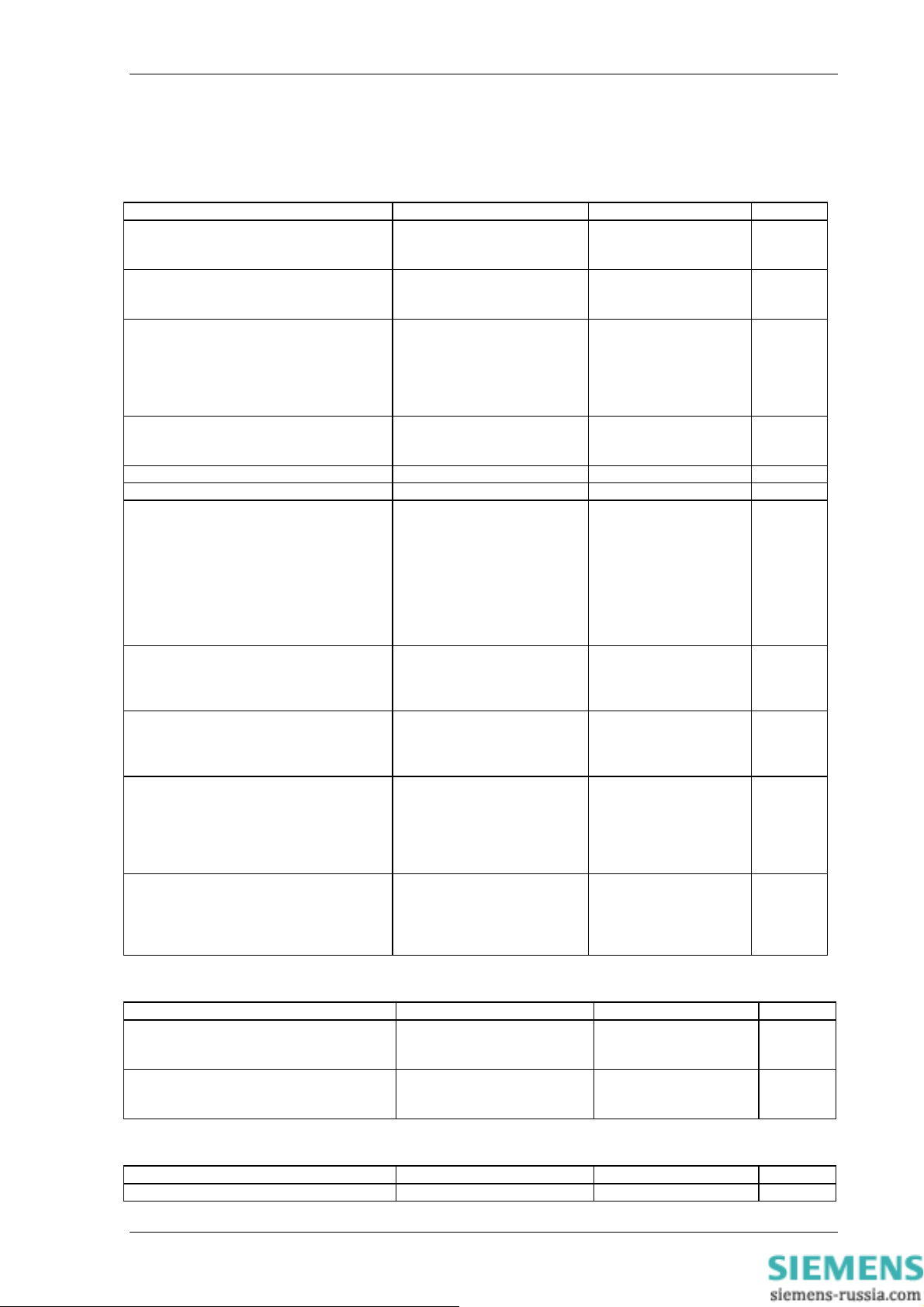
The DAD-N relay represents an integration of the protection elements required to provide a complete
Numerical High Impedance protection, with additional auxiliary and backup elements available to provide
integrated scheme solutions. The basic relay is a single differential zone as shown below. Other models
are also available which incorporate multiple zones of protection which may be used together with logic
schemes to form more complex busbar protection zones with check zone capability.
High Impedence Differential
Protected Zone
N
A
B
C
DAD-N-101
High Impedence Numerical Differential
AN1C1 - C3
CT
50
87/50
-1
87/50
-2
R RR
AN1
17
18
19
20
21
22
23
24
25
26
27
28
1A
Ia
5A
1A
Ib
5A
1A
Ic
5A
Figure 1 – DAD-N-101 Numerical High Impedance protection
2 Hardware Description
2.1 General
The structure of the relay is based upon the Modular II hardware and software platform illustrated in Figure
2 where the required cards plug in from the front after opening the front fascia. Modules are interconnected
by means of ribbon cable. The basic relay is supplied in a standard Epsilon case size E8. The Modular II
design provides commonality between products and spare parts across a range of protection and control
relays including Duobias, Ohmega, Delta, Tau and Iota.
©2010 Siemens Protection Devices Limited Chapter 1 Page 3 of 14

7SG12 DAD N Description of Operation
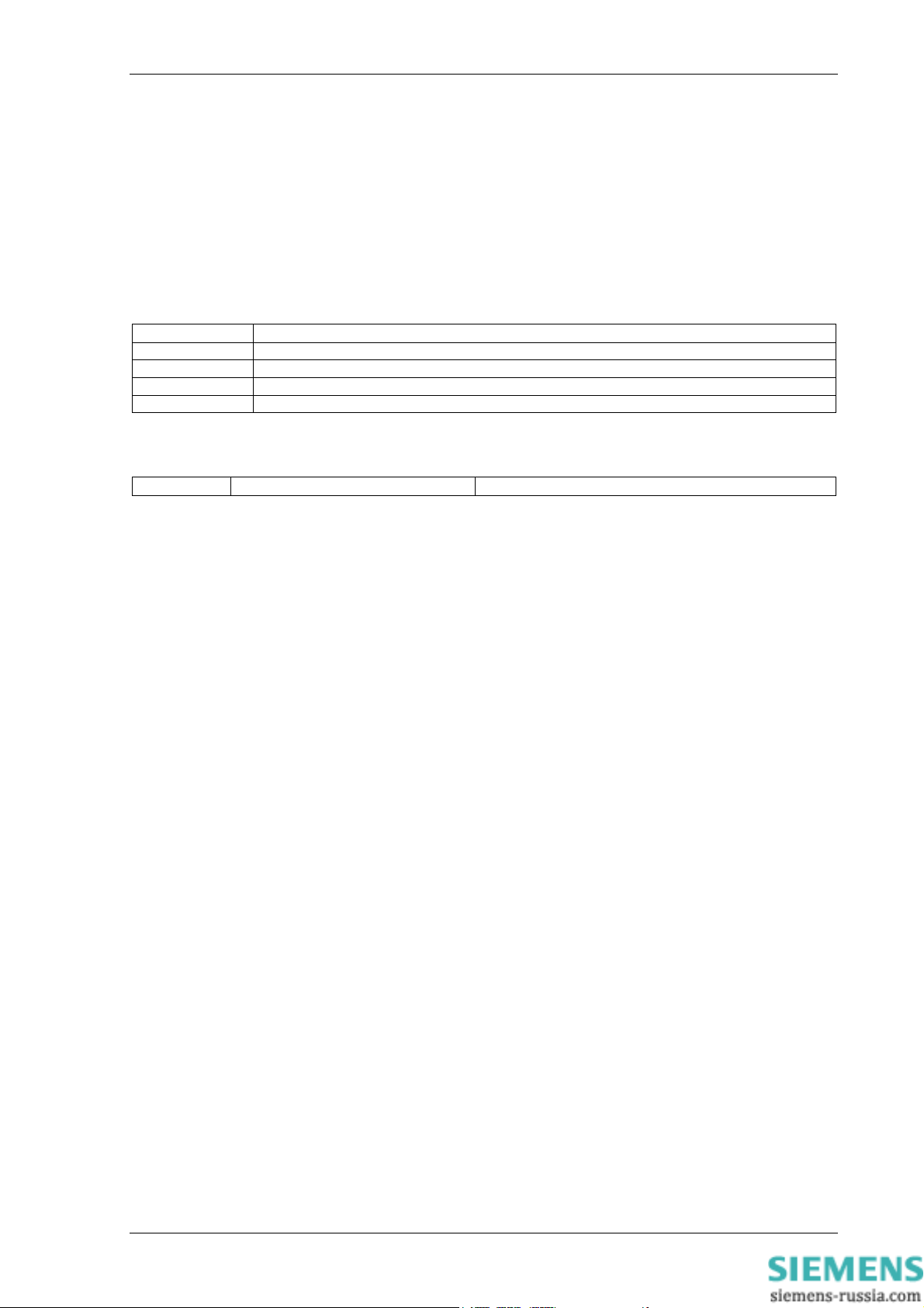
Configuration :
Analogue Inputs Status Inputs Output Relays Case Connections
3 11 13 E8 2621W11006
Each analogue module has up to four inputs; the first three are usually for measuring the CT secondary
line currents from each of the three phases A, B and C. The fourth channel is not used.
The unit consists of the following modules:
1) Analogue Input modules (4 x I )
2) One Controller CPU module
3) One Power Supply and Basic I/O module
4) Maximum of Four Output relay/Status Input Module
5) One Front Fascia
2.2 Analogue Inputs
One analogue module is used in the E8 case of 3 channels of current.
In order to ensure high accuracy true RMS measurements and accurate phase and slip frequency
calculations, the current signals are sampled at a minimum of 16 samples per cycle for both 50Hz and
60Hz system frequencies. This sampling rate also provides high accuracy and waveform storage records
2.3 Status Inputs
The relay may be fitted with up to 11 status inputs. The user can program the relay to use any status input
for any function. A timer is associated with each input and a pickup time setting may be applied to each
input. In addition each input may be logically inverted to allow easy integration of the relay within the user
scheme. Each input may be mapped to any front Fascia LED and/or to any Output Relay contact. This
allows the Relay to act as panel indication for alarms and scheme status without having to use additional
external flagging elements.
2.4 Output Relays
The relay may be fitted with 13 output relays, all of which are capable of handling circuit breaker tripping
duty. All relays are fully user configurable and can be programmed to operate from any or all of the control
functions. There are three relays on the Power Supply/Basic I/O module which have C/O contacts and 2
with N/O contacts. Additional modules may are fitted with 8 N/O contacts.
In their normal mode of operation output relays remain energised for a minimum of 100msec and a
maximum dependent on the energising condition duration. If required, however, outputs can be
programmed to operate as latching relays. These latched outputs can be reset by either pressing the
TEST/RESET button, or by sending an appropriate communications command.
The output relays can be used to operate the trip coils of the circuit breaker directly if the circuit breaker
auxiliary contacts are used to break the trip coil current and the contact rating of the relay output contacts
is not exceeded for 'make and carry' currents.
With a failed breaker condition the current 'break' may be transferred to the relay output contacts and
where this level is above the break rating of the contacts an auxiliary relay with heavy-duty contacts should
be utilised.
©2010 Siemens Protection Devices Limited Chapter 1 Page 4 of 14

7SG12 DAD N Description of Operation
2.5 Fascia LEDS
In the E8 case there are 16 user programmable red LED flag indicators. By opening the front panel it is
possible to insert a label strip into a slip in pocket, which provides legend information about the meaning of
each LED. The legend may be specified when ordering the relay or alternatively the user can create a
customized legend. The user can customise which LED is used for which purpose as well as being able to
program each LED as being latching or self –resetting.
2.6 Self Monitoring
The relay incorporates a number of self-monitoring features. Each of these features can initiate a
controlled reset recovery sequence, which can be used to generate an alarm output. In addition, the
Protection Healthy LED will give visual indication.
A watchdog timer continuously monitors the microprocessor. The voltage rails are also continuously
supervised and the microprocessor is reset if any of the rails falls outside of their working ranges. Any
failure is detected in sufficient time so that the microprocessor can be shut down in a safe and controlled
manner.
2.6.1 Protection Healthy/Defective
The normally closed contacts of relay 1 are used to signal protection defective, whilst the normally open
contacts are used to signal protection healthy. When the DC supply is not applied to the relay or a problem
is detected with the operation of the relay then this relay is de-energised and the normally closed contacts
make to provide an external alarm. When the relay has DC supply and it has successfully passed its selfchecking procedure then the Protection Healthy contacts are made and the Protection Defective contacts
are opened.
3 Protection Functions
3.1 Overall Differential (87/50-1, 87/50-2)
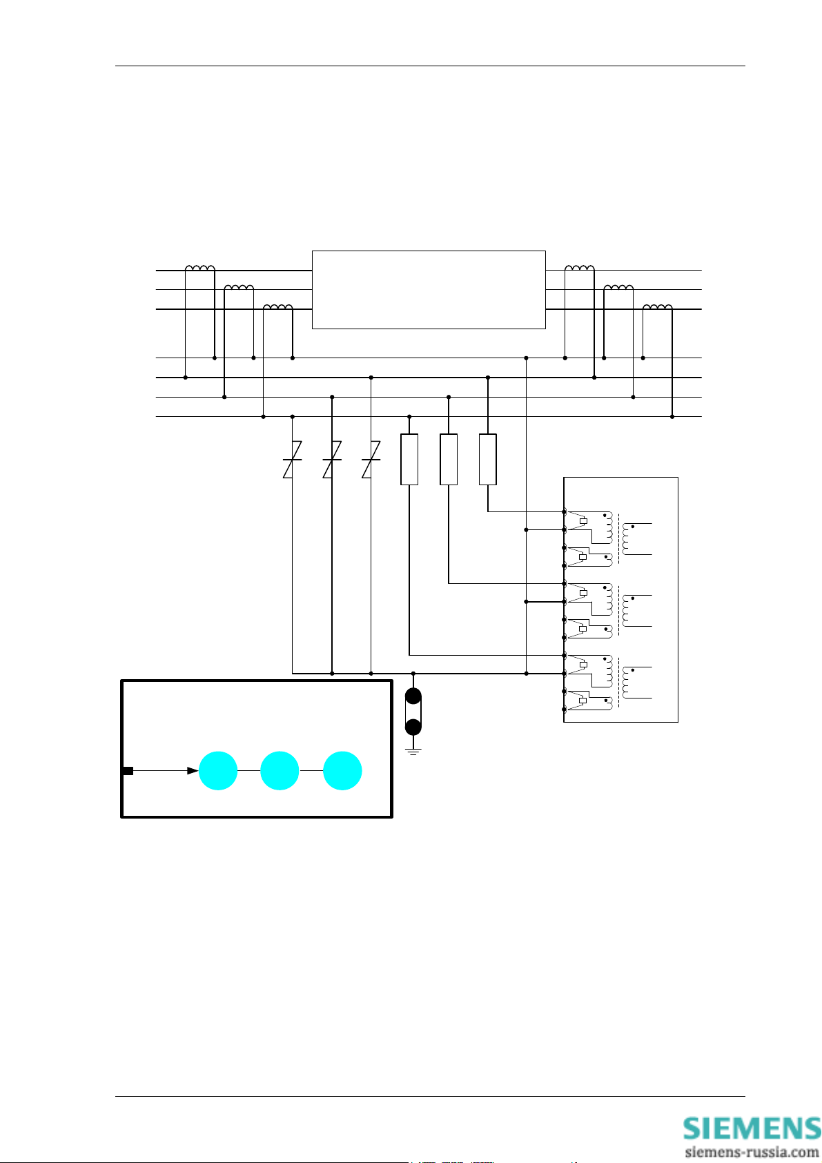
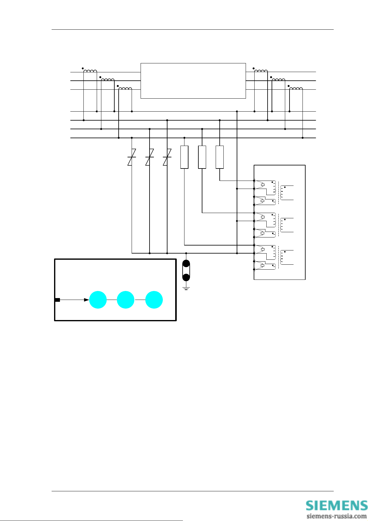
The Overall Differential protection uses the high impedance circulating current principle, a single line
diagram of such a scheme is shown in Figure 4 – High Impedance Differential Schematic. The protection
consists of a DTL over-current element 87/50 per phase which is used for tripping.
Transient stability under through fault conditions is a problem with many forms of differential protection,
due to variations in CT magnetising characteristics. When saturation is approached the current transformer
output waveforms become increasingly distorted with a high percentage of 3
algorithms employed in the Overall Differential protection ensure complete harmonic rejection thus
improving overall protection stability.
In addition the settings for high impedance differential protection are calculated assuming that one CT is
completely saturated. Using this worst case condition the voltage (determined by the value of the
stabilising resistor) and current settings for the 87/50 elements can be precisely calculated with known
stability margins. Intermediate conditions where the CT is only partially saturated increases the stability
margin. This approach enables schemes to be engineered with relatively low knee-point voltages.
There are two stages of protection, 87/50-1 and 87/50-2 both of which are identical.
rd
and other harmonics. The
3.2 CT Supervision (CT 50)
To check for CT continuity an overcurrent element (50) is available. During healthy CT conditions the
current in the differential circuit is zero. If one CT becomes open circuit the current contribution from that
CT will flow through the relay. If the setting is below this level of current the relay CT alarm will operate.
3.3 Trip Circuit Supervision
Status inputs on the relay can be used to supervise the trip circuit while the associated circuit breaker (CB)
is either open or closed. Each trip circuit monitored can independently be programmed to operate output
contacts, LEDs and events.
To use the function set ‘Trip Cct n Pickup Delay’ to the required value in the Trip Circuit Supervision Menu
and then map the ‘Trip Cct Fail n’ settings in the Status Input Menu, Output Relay Menu and LED Menu as
required.
©2010 Siemens Protection Devices Limited Chapter 1 Page 5 of 14

7SG12 DAD N Description of Operation
The Trip Circuit Timer(s) are inhibited whenever one or more of the status inputs selected is energised.
4 Other Features
4.1 Metering
The metering feature provides real-time data available from the relay fascia in the ‘Instruments Mode’ or
via the communications interface.
The following displays are available:
Differential currents (Primary and secondary)
Digital input status
Output relay status
Time and Date
4.2 Data Storage
4.2.1 General
Details of relay operation are recorded in three forms, namely Waveform records, Event records and Fault
Data records. All records are time and date stamped with a resolution of one millisecond.
4.2.2 Waveform Records.
The waveform record feature stores analogue and digital information for the current inputs, status inputs
and output relays and LED’s. Waveforms may be returned to VA TECH Reyrolle ACP Ltd for analysis.
The waveforms are stored with a sampling resolution of at least 16 samples per cycle depending upon
relay model. The waveform recorder has the ability to store records for the previous four trip operations of
the relay. These are labelled 1-4 with 1 being the most recent record. This however, can be altered using
the ‘Record Duration’ setting, which offers the following selection:
• Five records of one second duration
• Two records of two seconds duration
• One record of five seconds duration
The waveform recorder will be triggered automatically when any protection element operates. It can also
be triggered by any of the following means:
Via the ‘Trigger Storage” status input signal.
Via the IEC870-5-103 communications interface.
The waveform recorder has a settable pre-fault triggering capability.
4.2.3 Event Records
The event recorder feature allows the time tagging of any change of state (Event) of the relay. As an event
occurs, the actual event condition is logged as a record along with a time and date stamp to a resolution of
1 millisecond. There is capacity for a maximum of 500 event records that can be stored in the relay and
when the event buffer is full any new record will over-write the oldest. The following events are logged:
Change of state of Output Relays.
Change of state of Status Inputs.
Change of Settings and Settings Group
Change of state of any of the control functions of the relay.
4.2.4 Fault Recording
The fault type, led flag configuration, date and time of the last five faults are recorded for display via the
Fascia LCD.
Note : the real-time clock, waveform records, fault records and event records are all maintained, in the
event of loss of auxiliary d.c. supply voltage, by the backup storage capacitor. This capacitor has the ability
©2010 Siemens Protection Devices Limited Chapter 1 Page 6 of 14

7SG12 DAD N Description of Operation
to maintain the charges on the real-time clock IC and the SRAM memory device for typically 2-3 weeks
time duration.
4.3 Time Synchronisation
Time and date can be set either via the relay fascia using appropriate commands in the System Config
menu, via an IRIG-B input or via the communications interface
4.3.1 IRIG-B Time Synchronisation
A BNC connector on the relay rear provides an isolated IRIG-B GPS time synchronisation port. The IRIG-B
input expects a modulated 3-6 Volt signal and provides time synchronisation to the nearest millisecond.
4.3.2 IEC 60870-5-103 Time Synchronisation
Relays connected individually or in a ring or star configuration can be directly time synchronised using the
IEC 60870-5-103 global time synchronisation. This can be from a dedicated substation automation system
or from REYDISP EVOLUTION communications support software.
4.3.3 Real Time Clock Time Synchronisation
In the absence of IRIG-B and IEC60870 time synchronisation the relay contains a real time clock circuit
which maintains real time in the absence of DC supply.
4.4 Communications
Two fibre optic communication ports, COM1 and COM 2b are provided at the rear of the relay, which give
superior EMC performance. An isolated RS232 port, COM 2a, is provided at the front of the relay for local
access using a PC.
Communication is compatible with the IEC870-5-103 FT 1.2 transmission and application standards. For
communication with the relay via a PC (personal computer) a user-friendly software package, REYDISP
EVOLUTION, is available to allow transfer of the following:
Relay Settings
Waveform Records
Event Records
Fault Data Records
Instrument and meters
Control Functions
Communications operation is described in detail in Section 4 of this manual. For information about all
aspects of the communications protocol used in the Modular II range of relays see Section 4.
4.5 Settings Groups
Depending upon the relay model then up to eight alternative setting groups are provided, making it
possible to edit one group while the relay protection algorithms operate using another ‘active’ group. An
indication of which group is being viewed is given by the ‘Gn’ character in the top left of the display.
Settings that do not indicate Gn in the top left corner of the LCD are common to all groups.
A change of group can be achieved either locally at the relay fascia or remotely via a communication
interface command or via a status input change.
4.6 Password Feature
The programmable password feature enables the user to enter a 4 character alpha numeric code to secure
access to the relay settings. The relay is supplied with the password set to ‘NOT ACTIVE’, which means
that the password feature is disabled. The password must be entered twice as a security measure against
accident changes. Once a password has been entered then it will be required thereafter to change
settings. It can, however, be de-activated by using the password to gain access and by entering the
password ‘NONE’. Again this must be entered twice to de-activate the security system.
As soon as the user attempts to change a setting the password is requested before any setting alterations
are allowed. Once the password has been validated, the user is ‘logged on’ and any further changes can
©2010 Siemens Protection Devices Limited Chapter 1 Page 7 of 14

7SG12 DAD N Description of Operation
be made without re-entering the password. If no more changes are made within 1 hour then the user will
automatically be ‘logged off’, re-enabling the password feature.
Note that the password validation screen also displays a numerical code. If the password is lost or
forgotten, this code should be communicated to VA TECH Reyrolle ACP Ltd and the password can be
retrieved.
5 User Interface
The user interface is designed to provide a user-friendly method of entering settings and retrieving data
from the relay. The E8 relay fascia includes a 20 character by 2 line, backlit, liquid crystal display (LCD), 16
light emitting diodes (LED) and 5 push buttons.
5.1 Liquid Crystal Display
The liquid crystal display is used to present settings, instrumentation and fault data in a textual format on a
2 lines by 20-character interface.
5.2 Back Light Control
To conserve power the display backlighting is turned off if no push buttons are pressed for 5 minutes.
After an hour the whole display is de-activated. A setting within the “SYSTEM CONFIG MENU” allows the
timeout to be adjusted from 1 to 60 minutes and “OFF”, which means the backlight is always on.
5.3 LED Indications
The following indications are provided:
Protection Healthy – Green LED.
This LED is solidly illuminated to indicate that DC volts have been applied to the relay and that the relay is
operating correctly. If the internal relay watchdog detects a protection relay unhealthy condition then this
LED will continuously flash.
Programmable – Red LED.
An LED MENU is provided to map any relay output or any status input to any LED.
5.4 Keypad
Five pushbuttons are used to control the functions of the relay. They are labelled ENTER and CANCEL.
Note that the ► button is also labelled TEST/RESET.
When the relay front cover is in place only the ▼ and ► buttons are accessible. This allows read only
access to all the menu displays.
5.5 Relay Identifier
The Relay Identifier setting in the SYSTEM CONFIG MENU may be used to place a circuit identifier of up
to 16 alphanumeric characters onto the relay fascia. This information is also returned as part of the System
Information command from Reydisp Evolution Communications Support Software.
5.6 Settings Mode
5.6.1 Settings Adjustment
The push-buttons on the fascia are used to display the relay settings, display the operating signals, e.g.
currents, on the LCD and to reset the flag indication on the LCDs.
▼READ DOWN
In the Settings Display this push-button is used for scrolling down through a list of settings or signals.
In Settings Modification mode it is used for selecting the next value of (or decreasing) the displayed setting
or for deselecting a bit position in a particular control setting.
©2010 Siemens Protection Devices Limited Chapter 1 Page 8 of 14

7SG12 DAD N Description of Operation
▲READ UP
In Settings Display or Signal Displays this push-button is used for scrolling up through a list of settings or
signals.
In Settings Modification mode it is used for selecting the previous value of (or increasing) the displayed
setting or for selecting a bit position in a particular control setting.
ENTER
This push-button is used when the cover is removed to select between two modes of operation namely
Settings Display or Settings Modification.
When this push-button is pressed and a relay setting is being displayed part of the display will flash to
indicate that the setting being displayed can be modified by using the ▲ READ UP or ▼ READ DOWN
keys on the facia.
When the required value of the setting has been established it may be entered into the relay and acted
upon by pressing the ENTER key again.
CANCEL
This push-button is used when the cover is removed to return the relay display to its initial status. It can be
used to reject any alterations to the setting being modified provided the ENTER key has not been pressed
to accept the changes.
►TEST/RESET
This push-button is used to reset the fault indication on the LEDs on the fascia. It also acts as a lamp test
button, when pressed all LEDs will momentarily light up to indicate their correct operation.
The ▼ READ DOWN and ▲READ UP push-buttons may then be used to scroll through the various
signals.
5.6.2 Settings And Displays
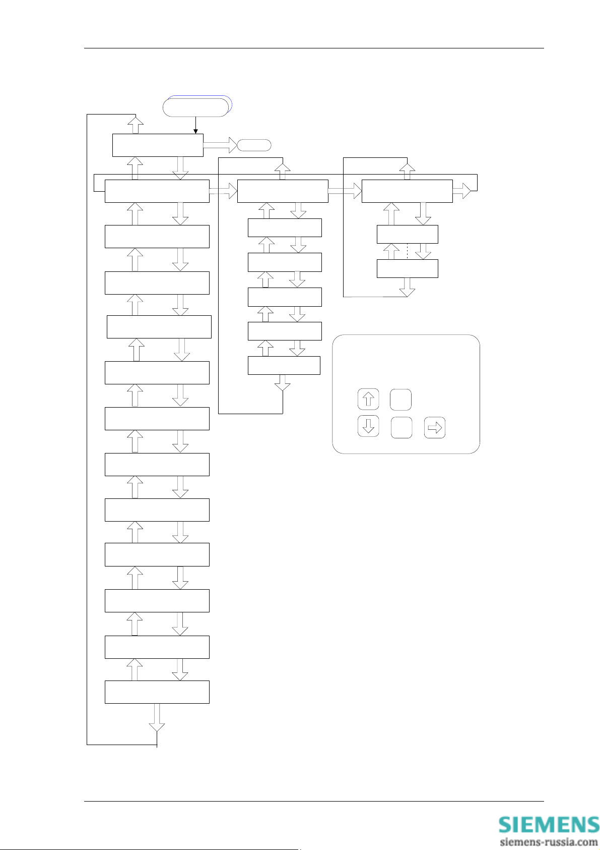
The display menu structure is shown in Figure 5. This diagram shows the three main modes of display,
which are the Settings Mode, Instruments Mode and the Fault Data Mode.
When the relay is first energised the user is presented with the following message: -
SETTINGS DEFAULTED
PRESS ENTER
This shows that the relay has been set with the standard factory default settings. If this message is
displayed ENTER must be pressed to acknowledge this initial condition, the display will then indicate the
relay identifier. e.g.
DAD-N-XXX
Pressing the ►TEST/RESET key on this display initiates an LED test. Pressing ▼ READ DOWN at this
display allows access to the three display modes, which are accessed in turn by pressing the
►TEST/RESET key.
The Settings Mode contains 11 setting sub-menu’s. These hold all of the programmable settings of the
relay in separate logical groups. The sub menus are accessed by pressing the
competitive, starting at less than £400 and peaking at around twice that►
menu and presents a list of all the settings within that sub menu. Pressing the ▼ READ DOWN key scrolls
through the settings until after the last setting in the sub menu after which the next sub menu will be
shown. Access to this group is via the same method as before. If a particular sub menu is not required to
be viewed then pressing ▼ READ DOWN will skip past that particular menu and show the next one in the
list. Note that all screens can be viewed even if the password is not known. The password only protects
against unauthorised changes to settings.
While viewing an editable screen pressing the ENTER key allows the user to change the displayed data. A
flashing character(s) will indicate the editable field. Pressing ▲ READ UP or ▼ READ DOWN scrolls
Prices are very
key. This enters the sub
©2010 Siemens Protection Devices Limited Chapter 1 Page 9 of 14

7SG12 DAD N Description of Operation
through the available setting values or, pressing ►TEST/RESET moves right through the edit fields. Note
that all settings can be incremented or decremented using the ▲ READ UP or ▼ READ DOWN keys and
they all wraparound so that to go from a setting minimum value to the maximum value it is quicker to press
the ▼ READ DOWN key, rather than scroll through every setting. Also, to facilitate quicker setting changes
an acceleration feature is available which if ▲ READ UP or ▼ READ DOWN are depressed and held,
then the rate of scrolling through the setting values increases.
If ESCAPE/CANCEL is pressed during a setting change operation the original setting value is restored and
the display is returned to the normal view mode.
If changes are made to the setting value then pressing ENTER disables the flashing character mode and
displays the new setting value. This is immediately stored in non-volatile memory.
The next sections give a description of each setting in the relay. The actual setting ranges and default
values can be found in the Relay Settings section of this manual.
5.7 Instruments Mode
In INSTRUMENT MODE metering points can be displayed to aid with commissioning, the following meters
are available
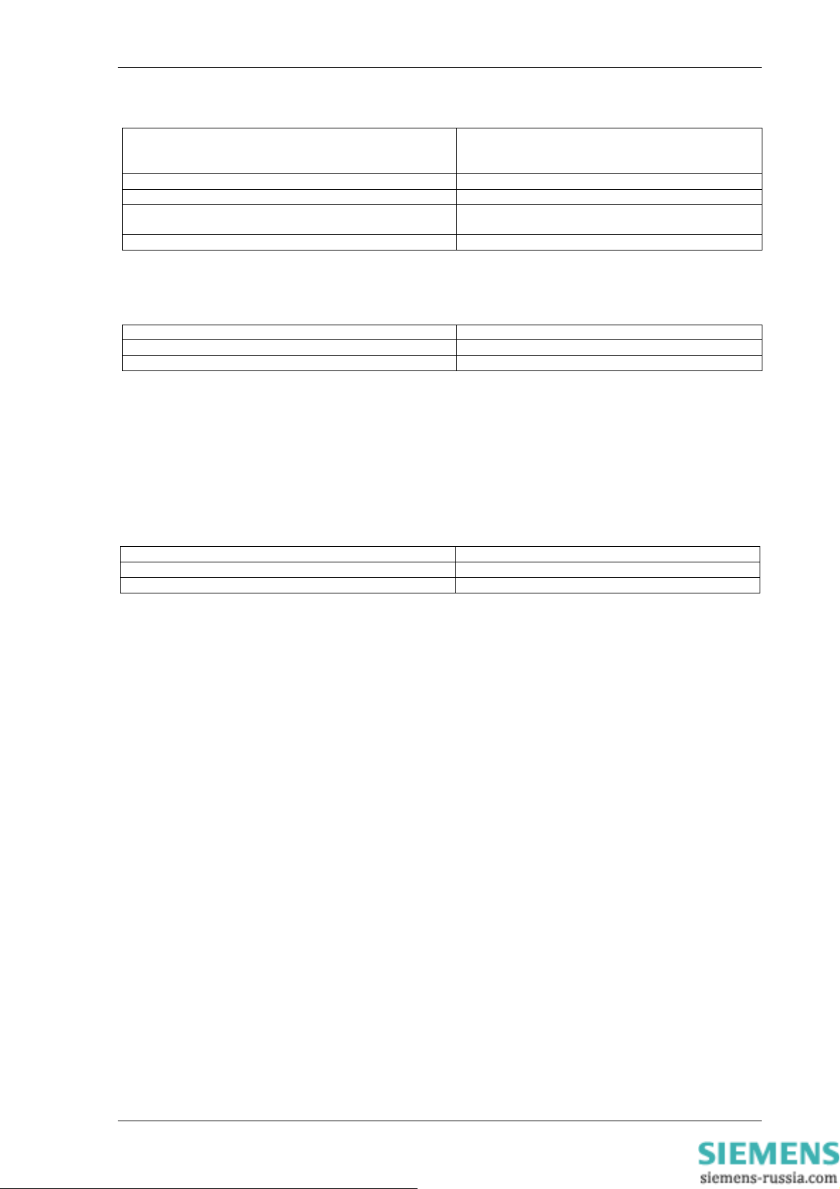
Instrument Description
[ DIFF METERS ]
--> press down <-Primary Currents
0.000 0.000 0.000 kA
Secondary Currents
0.000 0.000 0.000 A
Nominal Currents
0.00 0.00 0.00 xIn
[ MISC METERS ]
--> press down <-Status Inputs 1-16
---- ---- ---- ---Status Inputs 17-27
--Output Relays 1-16
---- ---- ---- ---Output Relays 17-29
---- Time & Date
13/08/2002 10:16:11
1) Display is different when fewer status inputs are fitted
2) Display is different when fewer output relays are fitted
Note that meters not designated as primary or secondary values are usually displayed as multiples of
nominal
i.e. x In, 1 Amp or 5 Amp.
Start of Differential current meters
Differential Primary currents
Differential Secondary currents
Differential Nominal currents
Start of miscellaneous meters
Displays the state of DC status inputs 1 to 161
Displays the state of DC status inputs 17 to 27
1
Displays the state of output relays 1 to 162
Displays the state of output relays 17 to 292
Time and Date
5.7.1 Hidden Instruments
At the “INSTRUMENTS MODE” title screen, pressing ENTER and DOWN simultaneously reveals some
additional metering for calibration purposes. The reference channels as well as DC offsets may be
displayed along with the RMS values in raw ADC counts. The relationship between current and ADC
counts is 1 x In = 600 counts.
5.8 Fault Data Mode
In “FAULT DATA MODE”, the time and date of relay operations are recorded together with a record of the
LED flag states.
5.9 Default Instruments Screens
The menu presentation of the various instruments allows the user to view a single screen at a time.
However, for in service use, it is desirable that a small number of high interest, user selectable screens are
presented automatically by default without user intervention. The instrument screens of interest to the user
e.g. those required to be presented to a visiting engineer for record purposes can be selected by the user
©2010 Siemens Protection Devices Limited Chapter 1 Page 10 of 14

7SG12 DAD N Description of Operation
by pressing ENTER when viewing the required screen. On pressing ENTER a ‘D’ symbol will appear at the
top right of that screen. The ‘D’ indicates that a screen is a ‘default screen’. To de-select a default screen,
simply press ENTER while on that particular screen and the ‘D’ symbol will be cleared.
01/01/2002 01:31:39
If no keys have been pressed for a pre-determined time the relay will jump to the default instrument display
regardless of where the menu has been left by the user. It will then scroll through each of the selected
default instruments and remain on each for approximately 5 seconds. The Default Screens Timer that sets
the time to elapse before the relay goes into the default instruments mode is found in the SYSTEM
CONFIG MENU.
Time & Date D
©2010 Siemens Protection Devices Limited Chapter 1 Page 11 of 14

6 Diagrams
7SG12 DAD N Description of Operation
Figure 2 – DAD-N in E8 case with front panel open
Figure 3 – DAD-N Rear View
©2010 Siemens Protection Devices Limited Chapter 1 Page 12 of 14

7SG12 DAD N Description of Operation
PHASE A
R
E
S
87/50-1
&
87/50-2
&
CT 50
Figure 4 – High Impedance Differential Schematic
©2010 Siemens Protection Devices Limited Chapter 1 Page 13 of 14
7SG12 DAD N Description of Operation
CANCEL/ESCAPE
RELAY IDENTIFIER
SETTINGS MODE
SYSTEM CONFIG MENU
-> to view
CT/VT CONFIG MENU
-> to view
DIFFERRENTIAL MENU
-> to view
CT SUPERVISION MENU
-> to view
TRIP CCT SUPERVISION
MENU -> to view
LED TEST
INSTRUMENTS
MODE
[ DIFF METERS ]
--> PRESS DOWN <--
[ MISC METERS ]
--> PRESS DOWN <--
Status Inputs 1-3
_ _ _
Output Relays 1-5
1 _ _ _ _
Time & Date
16/07/2001 11:49:17
FAULT DATA
MODE
FAULT 1
FAULT 5
NOTE : THE ARROWS IN THE DIAGRAM
REPRESENT THE KEY PRESSES REQUIRE D
TO NAVIGATE THE MENU SYSTEM.
READ UP
ENTER
TEST/RESET
CANCEL /
ESCAPE
READ DOWN
STATUS INPUT MENU
-> to view
REYLOGIC ELEMENTS
MENU -> to view
OUTPUT RELAY MENU
-> to view
LED MENU
-> to view
DATA STORAGE MENU
-> to view
COMMUNICATIONS MENU
-> to view
Figure 5 – DAD-N Menu Structure
©2010 Siemens Protection Devices Limited Chapter 1 Page 14 of 14
7SG12 DAD N Performance Specification
7SG12 DAD N
Numerical High Impedance Relay with CT Supervision
Document Release History
This document is issue 2010/02. The list of revisions up to and including this issue is:
Pre release
2010/02 Document reformat due to rebrand
R6 11/10/06 CT Supervision time delay accuracy added
R5 26/08/2005 Corrected CT burden on 1A tap.
Operate Time for CT Supervision added.
Time Delay for TCS added.
R4 22/07/2005 Revision 15 software and SEF Current Input Module 2513H10099.
R3 18/10/2004 Corrected Status Input minimum current for operation.
Corrected operating time variation over frequency.
R2 24/05/2004 Revision 12 software.
R1 24/10/2002 First Issue for comment.
Software Revision History
The copyright and other intellectual property rights in this document, and in any model or article produced from it
(and including any registered or unregistered design rights) are the property of Siemens Protection Devices
Limited. No part of this document shall be reproduced or modified or stored in another form, in any data retrieval
system, without the permission of Siemens Protection Devices Limited, nor shall any model or article be
reproduced from this document unless Siemens Protection Devices Limited consent.
While the information and guidance given in this document is believed to be correct, no liability shall be accepted
for any loss or damage caused by any error or omission, whether such error or omission is the result of
negligence or any other cause. Any and all such liability is disclaimed.
©2010 Siemens Protection Devices Limited

7SG12 DAD N Performance Specification
Contents
INTRODUCTION................................................................................................................................................3
1.
2. ACCURACY REFERENCE CONDITIONS ........................................................................................................3
3. ACCURACY INFLUENCING FACTORS ...........................................................................................................3
4. MODULAR II SPECIFICATION .........................................................................................................................3
4.1 Environmental Withstand ......................................................................................................................... 3
4.2 Auxiliary Energizing Quantity ................................................................................................................... 4
4.3 A.C Current Inputs ...................................................................................................................................5
4.4 Output Contacts....................................................................................................................................... 5
4.5 Status inputs ............................................................................................................................................5
4.6 Indication..................................................................................................................................................6
4.7 Settings And Configuration ...................................................................................................................... 6
4.8 Recording.................................................................................................................................................6
4.9 Communications ...................................................................................................................................... 6
4.10 IRIG-B Time Synchronisation................................................................................................................... 7
5. PROTECTION ELEMENTS ...............................................................................................................................7
5.1 Common Performance............................................................................................................................. 7
5.2 87/50-1, 87/50-2 Differential..................................................................................................................... 7
5.3 CT-50 CT Supervision..............................................................................................................................7
5.4 Trip Circuit Supervision............................................................................................................................ 7
©2010 Siemens Protection Devices Limited Chapter 2 Page 2 of 7
7SG12 DAD N Performance Specification
1. Introduction
The following document defines the technical and performance specification of the DAD-N Series relays. DAD-N
relays are based upon the VATECH ACP Ltd Modular II series of protection units.
Section 3 describes performance that is common to all Modular II protections.
Section 4 describes the performance of protection elements that may be fitted to DAD-N series relays. Therefore
for any one DAD-N series model, only the performance for those elements described in the Description of
Operation, as available in that model will be applicable.
Performance Data to:
IEC60255-6, IEC60255-6A and IEC60255-13.
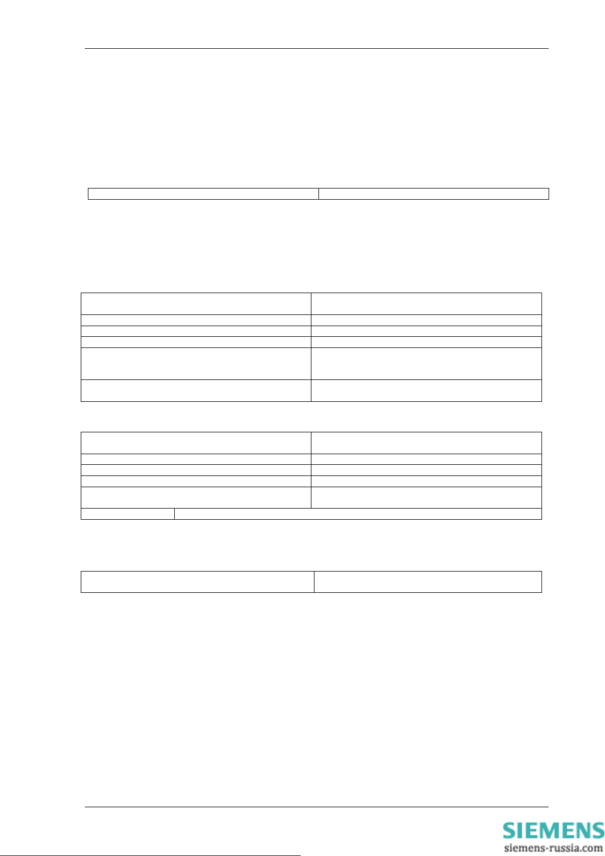
2. Accuracy Reference Conditions
General IEC60255
Parts 6, 6A & 13
Auxiliary Supply Nominal
Frequency 50 Hz
Ambient Temperature 20°C
3. Accuracy Influencing Factors
Temperature
Ambient range -10°C to +55°C
Variation over range
Frequency
Range 50Hz Model
Range 60Hz Model
Setting variation
Operating time variation
4. Modular II Specification
4.1 Environmental Withstand
Temperature - IEC 60068-2-1/2
Operating range -10°C to +55°C
Storage range -25°C to +70°C
Humidity - IEC 60068-2-3
Operational test 56 days at 40°C and 95% RH
Transient Overvoltage –IEC 60255-5
Between all terminals and earth or between any two
independent circuits without damage or flashover
Insulation - IEC 60255-5
Between all terminals and earth 2.0kV rms for 1 min
Between independent circuits 2.0kV rms for 1 min
Across normally open contacts 1.0kV rms for 1 min
High Frequency Disturbance IEC 60255-22-1 Class III
Variation
2.5kV Common (Longitudinal) Mode
1.0kV Series (Transverse) Mode
Electrostatic Discharge IEC 60255-22-2 Class IV
Variation
≤ 5%
47Hz to 52Hz
57Hz to 62Hz
≤ 5%
≤ 5%
5kV 1.2/50µs 0.5J
≤ 5%
≤ 5%
©2010 Siemens Protection Devices Limited Chapter 2 Page 3 of 7
7SG12 DAD N Performance Specification
8kV contact discharge
Conducted & Radiated Emissions EN 55022 Class A (IEC 60255-25)
Conducted 0.15MHz – 30MHz
Radiated 30MHz – 1GHz
Conducted Immunity (IEC 61000-4-6; IEC 60255-22-6)
Variation
0.15MHz – 80MHz 10V rms 80% modulation
Radiated Immunity IEC60255-22-3 Class III
Variation
80MHz to 1000MHz, 10V/m
80% modulated
Fast Transient – IEC 60255-22-4 Class IV
Variation
4kV 5/50ns 2.5kHz repetitive
Surge Impulse IEC 61000-4-5 Class IV; (IEC 60255-22-5)
Variation
4KV Line-Earth (O/C Test voltage 10%)
2KV Line-Line
Vibration (Sinusoidal) –IEC 60255-21-1 Class 1
Variation
Vibration response 0.5gn
Vibration endurance 1.0gn
Shock and Bump–IEC 60255-21-2 Class 1
Variation
Shock response 5 gn 11ms
Shock withstand 15 gn 11ms
Bump test 10 gn 16ms
Seismic – IEC 60255-21-3 Class 1
Variation
Seismic Response 1gn
Mechanical Classification
Durability
≤ 5%
≤ 5%
≤ 5%
≤ 5%
≤ 10
≤ 5%
≤ 5%
≤ 5%
≤ 5%
≤ 5%
≤ 5%
In excess of 106 operations
4.2 Auxiliary Energizing Quantity
DC Power Supply
Nominal Operating Range
24/30V 18V to 37.5V dc
50/110V 37.5V to 137.5V dc
220/250V 175V to 286V dc
Auxiliary DC Supply – IEC 60255-11
Allowable superimposed ac component
Allowable breaks/dips in supply (collapse to zero
from nominal voltage)
D.C. Burden
Quiescent (Typical) 15
Max 27
©2010 Siemens Protection Devices Limited Chapter 2 Page 4 of 7
≤ 12% of DC voltage
≤ 20ms
7SG12 DAD N Performance Specification
4.3 A.C Current Inputs
1 Amp and 5 Amp current inputs are both available on the rear terminal blocks for most functions except
Capacitor Unbalance.
Thermal Withstand
Continuous and Limited Period Overload
AC Current Inputs
3.0 x In Continuous
3.5 x In for 10 minutes
4.0 x In for 5 minutes
5.0 x In for 3 minutes
6.0 x In for 2 minutes
250A for 1 second
625A peak for 1 cycle
A.C. Burden
A.C. Burden
1A tap 0.2 VA
5A tap 0.3 VA
NB. Burdens are measured at nominal rating.
4.4 Output Contacts
Output contacts functionality is fully programmable. The basic I/O module has 5 output contacts three of which are
change over. Additional modules can be added with consequential increases in case size, to provide more
contacts. These are added in-groups of eight up to a maximum of 29
Output Contact Performance
Contact rating to IEC 60255-0-2.
Carry continuously 5A ac or dc
Make and Carry
(limit L/R ≤ 40ms and V ≤ 300 volts)
for 0.5 sec 20A ac or dc
for 0.2 sec 30A ac or dc
Break
(limit ≤ 5A or ≤ 300 volts)
Ac resistive 1250VA
Ac inductive
Dc resistive 75W
Dc inductive
Minimum number of operations 1000 at maximum load
Minimum recommended load 0.5W, limits 10mA or 5V
250VA @ PF ≤ 0.4
30W @ L/R ≤ 40 ms
50W @ L/R ≤ 10 ms
4.5 Status inputs
Status Inputs functionality is fully programmable. The basic I/O module has 3 status inputs these can be set to
high speed for signalling. Additional modules can be added to provide more inputs. Additional inputs are added ingroups of eight up to a maximum of 27. A pickup timer is associated with each input and each input may be
individually inverted where necessary.
Nominal Voltage Operating Range
30 / 34 18V to 37.5V
48 / 54 37.5V to 60V
110 / 125 87.5V to 137.5V
220 / 250 175 to 280V
NB: the status input operating voltage does not have to be the same as the power supply voltage.
©2010 Siemens Protection Devices Limited Chapter 2 Page 5 of 7
7SG12 DAD N Performance Specification
Status Input Performance
Minimum DC current for operation 48V 10mA
110V 2.25mA
220V 2.16mA
Reset/Operate Voltage Ratio
Typical response time < 5ms
Typical response time when programmed to energise an
output relay contact
Minimum pulse duration 40ms
To meet the requirements of ESI 48-4 then 48V status inputs should be ordered together with external dropper
resistors as follows:-
Status Input External Dropper Resistances
Nominal Voltage Resistor Value (Wattage)
110 / 125V 2k7 ± 5% ; (2.5W)
220 / 250V 8k2 ± 5% ; (6.0W)
Each status input has an associated timer that can be programmed to give time-delayed pick-up. The pick-up
timers can be set to 20ms to provide immunity to an AC input signal. Status inputs will then not respond to the
following:
• 250V RMS 50/60Hz applied for two seconds through a 0.1μF capacitor.
• 500V RMS 50/60Hz applied between each terminal and earth.
• Discharge of a 10μF capacitor charged to maximum DC auxiliary supply voltage.
≥ 90%
< 15ms
4.6 Indication
There are two types of LED indication, General and Protection Healthy.
Case Size Number of LEDs
E8 16 General + Protection Healthy
E12/E16 32 General + Protection Healthy
All General LED indication is fully configurable by the user. All General indications are stored in non-volatile
memory without the use of an internal backup battery.
4.7 Settings And Configuration
Settings changes may be done via the front panel user-friendly fascia keypad and LCD or via standard Reydisp
Evolution windows software either locally or remotely. Settings changes are stored in EEPROM memory.
Configuration changes may be achieved locally via the front serial port with a Windows based toolbox support
package. Configuration changes and software upgrades are stored in Flash EPROM memory.
4.8 Recording
Up to 5 fault records may be stored within the relay, Fault records are accessible via the front panel showing the
date and time of trips. New faults automatically overwrite the oldest fault record when they occur.
Waveform records are automatically stored whenever a trip is generated. Waveform recording can also be
triggered by the status inputs. New waveform records automatically overwrite the oldest waveform record when
they are triggered. The exact number and duration of waveform records, for any particular relay model, is
available from the Relay Settings section of this Manual in the Data Storage Menu listing.
Up to 500 time tagged event records are stored within the relay. New events automatically overwrite the oldest
event record when the 500 are used up.
4.9 Communications
IEC 60870-5-103 communications is standard on Reyrolle Modular II numerical product range. IEC 60870-5-103
has the advantage of built in time synchronisation of all devices, reduced communications overhead, high data
security and compatibility with all of the major substation automation and control systems.
COM1 is a dedicated rear fibre optic serial port. COM2 can be auto-switched between rear fibre optic serial port
and a front isolated RS232 serial port. IEC 60870-5-103 may be directed to use either COM1 or COM2.
All fibre optic ports can be star connected to a Sigma passive hub or simply daisy-chained in a loop-in loop-out
configuration with other Reyrolle relays e.g. Argus, Delta, Ohmega, Tau.
©2010 Siemens Protection Devices Limited Chapter 2 Page 6 of 7
7SG12 DAD N Performance Specification
4.10 IRIG-B Time Synchronisation
The relay incorporates an IRIG-B time synchronisation port as standard for connection to a GPS time receiver.
The input accepts an a.c. modulated input signal that should be in the range 3Vp-p or 6Vp-p.
5. Protection Elements
5.1 Common Performance
Disengaging Time 30ms
Note: Output contacts have a default minimum dwell time of 100ms, which may be altered via a setting, after
which the disengaging time is as above.
5.2 87/50-1, 87/50-2 Differential
Phase segregated High impedance Overall Differential scheme using external stabilizing resistors. Function is
insensitive to third harmonic currents.
Pickup
Reset 95% of Is
Repeatability ± 2%
Transient Overreach 5%
Operate Time
2 x Setting
4 x Setting
Time Delay
± 5% of setting or ± 0.01 I
whichever is the greater
Operate Time
1 cycle
< 1 cycle
± 1% or ± 5ms
whichever is the greater
n
5.3 CT-50 CT Supervision
Pickup
Reset 95% of Is
Repeatability ± 2%
Transient Overreach 5%
Operate Time
2 x Setting
Time Delay Time Delay setting +/- 5% or +/- 10 milliseconds, whichever is the greater**
**NB: - Minimum Time Delay setting is 100milliseconds
± 5% of setting or ± 0.01 I
whichever is the greater
Operate Time
< 1.5 cycles
n
5.4 Trip Circuit Supervision
Time Delay
± 1% or +0, +20 ms
whichever is the greater
©2010 Siemens Protection Devices Limited Chapter 2 Page 7 of 7

7SG12 DAD N Relay Settings
7SG12 DAD N
Numerical High Impedance Relay with CT Supervision
Document Release History
This document is issue 2010/02. The list of revisions up to and including this issue is:
Pre release
Revision Date Change
R12 26-08-2005 Corrected TCS ranges and units.
R11 15-08-2005 Added 2nd stage 87/50-2.
R10 09-02-2005 Corrected status input menu settings order
R9 08-12-2004 R14 Software version adds in Dual IEC 60870-5-103 and Modbus-RTU
R8 23-09-2004 E12/E16 label added
R7 09-09-2004 CT Supervision event added, now GI. Logic diagrams updated
R6 26-01-2004 Corrected 74TC typo
R5 22/01/2004 Diagram added to front sheet
R4 19/01/2004 Brought up to date with R12 binary, added in new data storage features
R3 18/06/2003 Phase segregated outputs added
R2 17/06/2003 Logic diagrams added, menu’s adjusted
R1 30/05/2003 First Version
Software Revision History
2010/02 Document reformat due to rebrand
Corrected TCS events numbers
Minimum setting value reduced to 0.005xIn for 87/50 and 0.001xIn for CT 50
using 2513H10099 4xSEF analogue module.
Time steps now 5ms.
IEC Output relay drive added.
Primary and Secondary metering resolution improved.
communications protocols, settings group change from status inputs
Output Relay defaults now only for General Starter and General Trip
Reylogic diagrams updated
8 settings groups as standard
The copyright and other intellectual property rights in this document, and in any model or article produced from it
(and including any registered or unregistered design rights) are the property of Siemens Protection Devices
Limited. No part of this document shall be reproduced or modified or stored in another form, in any data retrieval
system, without the permission of Siemens Protection Devices Limited, nor shall any model or article be
reproduced from this document unless Siemens Protection Devices Limited consent.
While the information and guidance given in this document is believed to be correct, no liability shall be accepted
for any loss or damage caused by any error or omission, whether such error or omission is the result of
negligence or any other cause. Any and all such liability is disclaimed.
©2010 Siemens Protection Devices Limited
7SG12 DAD N Relay Settings
P1 P2
S1
S2
N
A
B
C
DAD-N-101
High Impedence Differential
Protected Zone
R RR
P1 P2
S1 S2
AN1
17
18
19
20
21
22
23
24
25
26
27
28
1A
Ia
5A
Ib
Ic
AN1C1 - C3
CT50
87/
50-1
87/
50-2
Model No Cat No Configuration No
DAD-N-101
DA1-101 2414H80001R15
Date: 24/02/2010 12:55:00
©2010 Siemens Protection Devices Limited Chapter 3 Page 2 of 20

7SG12 DAD N Relay Settings
Contents
1 DAD-N-101 RELAY SETTING LIST..................................................................................................................4
1.1 SYSTEM CONFIG MENU
1.2 CT/VT CONFIG MENU
1.3 DIFFERENTIAL MENU
1.4 CT SUPERVISION MENU
1.5 TRIP CIRCUIT SUPERVISION MENU
1.6 STATUS INPUT
1.7 STATUS INPUT
1.8 REYLOGIC ELEMENT
1.9 OUTPUT RELAY MENU
1.10 LED MENU
1.11 DATA STORAGE MENU
1.12 COMMUNICAT
2 INSTRUMENTS
3 IEC 60870-5-103 COMMUNICATIONS INFORMATION .................................................................................12
3.1 IEC 60870-5-103 Semantics in monitor direction
3.2 IEC 60870-5-103 Semantics in control direction
4 MODBUS SEMA
4.1 COILS
4.2 INPUT
4.3 REGIST
5 REYLOGIC DIA
....................................................................................................................................................15
S.................................................................................................................................................. 16
ERS..........................................................................................................................................17
MENU ........................................................................................................................... 5
TIMING MENU..............................................................................................................6
..............................................................................................................................................9
IONS MENU.................................................................................................................. 10
...............................................................................................................................................11
NTICS ...................................................................................................................................15
GRAMS..................................................................................................................................17
........................................................................................................................4
............................................................................................................................4
............................................................................................................................4
.......................................................................................................................5
....................................................................................................5
MENU................................................................................................................. 7
..........................................................................................................................7
.......................................................................................................................10
...................................................................................12
....................................................................................14
6 LABEL INSERTS.............................................................................................................................................19
©2010 Siemens Protection Devices Limited Chapter 3 Page 3 of 20
7SG12 DAD N Relay Settings
1 DAD-N-101 Relay Setting List
1.1 System Config Menu
Description Range Default Setting
Active Group
Selects which settings group is currently
activated
View/Edit Group
Selects which settings group is currently
being displayed
Default Screens Timer
Selects the time delay after which, if no
key presses have been detected, the
relay will begin to poll through any
screens which have been selected as
default instruments screens
Backlight timer
Controls when the LCD backlight turns
off
Date Date 1/1/1980
Time Time 00:00:00
Select Grp Mode
Mode of operation of group change from
status input. Edge triggered ignores the
status input once it has changed to the
relevant group, where as with Level
triggered the relay will only stay in the
group it has changed to whilst the status
input is being driven, after which it
returns to the previous group.
Clock Sync. From Status
Real time clock may be synchronised
using a status input (See Clock Sync. in
Status Input Menu)
Operating Mode
To allow access to change configuration
files using Reylogic Toolbox the relay
must be placed Out Of Service.
Change Password
Allows a 4 character alpha code to be
entered as the password. Note that the
display shows a password dependant
encrypted code on the second line of the
display
Relay Identifier
An alphanumeric string shown on the
LCD normally used to identify the circuit
the relay is attached to or the relays
purpose
1,2…8 1
1,2…8 1
OFF, 1,2,5,10,15,30,60 min 60 min
OFF, 1,2,5,10,15,30,60 min 5 Min
Edge triggered,
Level triggered
Disabled, Seconds,Minutes Minutes
Local, Remote, Local Or
Remote, Out Of Service
AAAA…ZZZZ “NONE” displayed as
Up to 16 characters DAD-N-101
Edge triggered
Local Or Remote
“NOT ACTIVE”
1.2 CT/VT Config Menu
Description Range Default Setting
CT Input
Selects whether 1 or 5 Amp terminals
are being used
CT Ratio
CT ratio to scale primary current
instruments
1,5 A 1 A
5:0.2…5000:7 2000:1
1.3 Differential Menu
Description Range Default Setting
87/50-1 Element Disabled, Enabled Disabled
©2010 Siemens Protection Devices Limited Chapter 3 Page 4 of 20
 Loading...