

Siemens 6DR50 Series, 6DR53 Series, 6DR51 Series, 6DR52 Series, SIPART PS2 Operating Instructions Manual
Page 1
SIPART
Electropneumatic positioners
SIPART PS2 with and without HART
Operating Instructions
Edition 09/2014
Answers for industry.
Page 2

Page 3

SIPART PS2 with and without HART
___________________
___________________
___________________
___________________
___________________
___________________
___________________
___________________
___________________
___________________
___________________
___________________
___________________
___________
___________________
___________________
SIPART
Electropneumatic positioners
SIPART PS2 with and without
HART
Operating Instructions
6DR50.. - Positioner without HART
6DR51..
6DR52..
6DR53..
proof
09/2014
A5E00074631
Introduction
1
Safety information
2
Description
3
Installing/mounting
4
Connection
5
Operating
6
Commissioning
7
Functional safety
8
Parameterizing/addressing
9
Alarm, error, and system
messages
10
Service and maintenance
11
Technical data
12
Dimension drawings
13
Spare
parts/accessories/scope of
delivery
14
Appendix
A
Abbreviations
B
- Positioner with HART, not explosion-proof
- Positioner with HART, explosion-proof
- Positioner without HART, not explosion-
-12
Page 4

Siemens AG
Industry Sector
Postfach 48 48
90026 NÜRNBERG
GERMANY
Order number: A5E00074631
Ⓟ
Copyright © Siemens AG 2014.
All rights reserved
Legal information
Warning notice system
DANGER
indicates that death or severe personal injury will result if proper precautions are not taken.
WARNING
indicates that death or severe personal injury may result if proper precautions are not taken.
CAUTION
indicates that minor personal injury can result if proper precautions are not taken.
NOTICE
indicates that property damage can result if proper precautions are not taken.
Qualified Personnel
personnel qualified
Proper use of Siemens products
WARNING
Siemens products may only be used for the applications described in the catalog and in the relevant technical
maintenance are required to ensure that the products operate safely and without any problems. The permissible
ambient conditions must be complied with. The information in the relevant documentation must be observed.
Trademarks
Disclaimer of Liability
This manual contains notices you have to observe in order to ensure your personal safety, as well as to prevent
damage to property. The notices referring to your personal safety are highlighted in the manual by a safety alert
symbol, notices referring only to property damage have no safety alert symbol. These notices shown below are
graded according to the degree of danger.
If more than one degree of danger is present, the warning notice representing the highest degree of danger will
be used. A notice warning of injury to persons with a safety alert symbol may also include a warning relating to
property damage.
The product/system described in this documentation may be operated only by
task in accordance with the relevant documentation, in particular its warning notices and safety instructions.
Qualified personnel are those who, based on their training and experience, are capable of identifying risks and
avoiding potential hazards when working with these products/systems.
Note the following:
documentation. If products and components from other manufacturers are used, these must be recommended
or approved by Siemens. Proper transport, storage, installation, assembly, commissioning, operation and
All names identified by ® are registered trademarks of Siemens AG. The remaining trademarks in this publication
may be trademarks whose use by third parties for their own purposes could violate the rights of the owner.
We have reviewed the contents of this publication to ensure consistency with the hardware and software
described. Since variance cannot be precluded entirely, we cannot guarantee full consistency. However, the
information in this publication is reviewed regularly and any necessary corrections are included in subsequent
editions.
for the specific
10/2014 Subject to change
Page 5

Table of contents
1 Introduction ........................................................................................................................................... 11
2 Safety information ................................................................................................................................. 15
3 Description ............................................................................................................................................ 19
4 Installing/mounting ................................................................................................................................ 31
1.1 Purpose of this documentation ............................................................................................... 11
1.2 History ..................................................................................................................................... 11
1.3 Purpose ................................................................................................................................... 12
1.4 Checking the consignment ..................................................................................................... 12
1.5 Transportation and storage ..................................................................................................... 13
1.6 Product information ................................................................................................................. 13
1.7 Notes on warranty ................................................................................................................... 13
2.1 Requirements for safe use ...................................................................................................... 15
2.1.1 Warning symbols on the device .............................................................................................. 15
2.1.2 Laws and directives ................................................................................................................ 16
2.1.3 Conformity with European directives ...................................................................................... 16
2.2 Improper device modifications ................................................................................................ 16
2.3 Requirements for special applications .................................................................................... 17
2.4 Use in hazardous areas .......................................................................................................... 17
3.1 Function .................................................................................................................................. 19
3.2 Structure ................................................................................................................................. 19
3.2.1 Overview of structure .............................................................................................................. 19
3.2.2 Nameplate layout .................................................................................................................... 22
3.3 Device components ................................................................................................................ 24
3.3.1 Overview of device components ............................................................................................. 24
3.3.2 Basic electronics ..................................................................................................................... 25
3.4 Mode of operation ................................................................................................................... 26
3.4.1 Control algorithm ..................................................................................................................... 27
3.4.2 Block circuit diagram for single-acting or double-acting actuators ......................................... 28
3.4.3 Mode of operation of the HART function ................................................................................ 29
3.4.4 HART system configuration .................................................................................................... 29
3.4.5 SIMATIC PDM ........................................................................................................................ 30
4.1 Basic safety instructions ......................................................................................................... 31
4.1.1 Proper mounting ..................................................................................................................... 34
4.2 Mounting the linear actuator ................................................................................................... 34
4.3 Mounting the part-turn actuator .............................................................................................. 40
SIPART PS2 with and without HART
Operating Instructions, 09/2014, A5E00074631-12
3
Page 6

Table of contents
5 Connection ........................................................................................................................................... 69
6 Operating ............................................................................................................................................. 103
4.4 Using the positioner in a humid environment ......................................................................... 44
4.5 Positioners subjected to fast acceleration or strong vibration ............................................... 45
4.6 External position detection ..................................................................................................... 48
4.7 Installing option modules ....................................................................................................... 48
4.7.1 General information on installing option modules .................................................................. 48
4.7.1.1 Installing optional modules in the standard and intrinsically safe version ............................. 49
4.7.1.2 Installing the optional modules in the "flameproof enclosure" version ................................... 52
4.7.2 Position feedback module ...................................................................................................... 56
4.7.3 Alarm module ......................................................................................................................... 57
4.7.4 Slot initiator alarm module ..................................................................................................... 59
4.7.4.1 Setting the limits of the slotted initiator alarm module ........................................................... 61
4.7.5 Mechanical limit switch module .............................................................................................. 62
4.7.5.1 Setting the limits of the mechanical limit switch module ........................................................ 64
4.7.5.2 Label set for limit contact module .......................................................................................... 65
4.7.6 EMC filter module................................................................................................................... 66
4.7.7 Accessories ............................................................................................................................ 68
5.1 Basic safety instructions ........................................................................................................ 69
5.2 Electric ................................................................................................................................... 73
5.2.1 Device 6DR5..0/1/2/3-0N or 6DR5..5-0E ............................................................................... 73
5.2.1.1 Basic electronics with 6DR5..0/1/2/3-0N or 6DR5..5-0E ....................................................... 73
5.2.1.2 Option modules with 6DR5..0/1/2/3-0N or 6DR5..5-0E ......................................................... 77
5.2.2 Device 6DR5..0/1/2/3-0E/D/F/G/K ......................................................................................... 81
5.2.2.1 Breakdown of the article numbers 6DR5..0/1/2/3-0E/D/F/G/K .............................................. 81
5.2.2.2 Basic electronics with 6DR5..0/1/2/3-0E/D/F/G/K .................................................................. 82
5.2.2.3 Option modules with 6DR5..0/1/2/3-0E/D/F/G/K ................................................................... 86
5.2.3 Connecting NCS to EMC filter module .................................................................................. 91
5.2.4 Connecting the external position detection system to the EMC filter module ....................... 93
5.3 Pneumatic .............................................................................................................................. 95
5.3.1 Pneumatic connections .......................................................................................................... 95
5.3.1.1 Pneumatic connection for 6DR5..0/1/2/3 ............................................................................... 95
5.3.1.2 Integrated pneumatic connection ........................................................................................... 95
5.3.1.3 Pneumatic connection for 6DR5..5-0E... ............................................................................... 96
5.3.1.4 Reaction to failure of auxiliary powers ................................................................................... 97
5.3.2 Pneumatic connection .......................................................................................................... 100
5.4 Restrictors ............................................................................................................................ 101
6.1 Operating elements .............................................................................................................. 103
6.1.1 Display ................................................................................................................................. 103
6.1.2 Buttons ................................................................................................................................. 105
6.1.3 Firmware version.................................................................................................................. 106
6.2 Operating modes.................................................................................................................. 106
6.2.1 Overview of operating modes .............................................................................................. 106
6.2.2 Changing the operating mode .............................................................................................. 107
6.2.3 Overview of configuration .................................................................................................... 108
6.2.4 Description of operating modes ........................................................................................... 108
6.2.5 Optimization of controller data ............................................................................................. 111
SIPART PS2 with and without HART
4 Operating Instructions, 09/2014, A5E00074631-12
Page 7

Table of contents
7 Commissioning ................................................................................................................................... 113
8 Functional safety ................................................................................................................................. 139
9 Parameterizing/addressing .................................................................................................................. 145
7.1 Basic safety instructions ....................................................................................................... 113
7.2 Commissioning overview ...................................................................................................... 115
7.3 Sequence of automatic initialization ..................................................................................... 117
7.4 Purge air switching ................................................................................................................ 122
7.5 Commissioning linear actuators ............................................................................................ 123
7.5.1 Preparing linear actuators for commissioning ...................................................................... 123
7.5.2 Automatic initialization of linear actuators............................................................................. 125
7.5.3 Manual initialization of linear actuators ................................................................................. 127
7.6 Commissioning part-turn actuators ....................................................................................... 131
7.6.1 Preparing part-turn actuators for commissioning .................................................................. 131
7.6.2 Automatic initialization of part-turn actuators ........................................................................ 132
7.6.3 Manual initialization of part-turn actuators ............................................................................ 134
7.7 Device replacement .............................................................................................................. 137
8.1 Range of applications for functional safety ........................................................................... 139
8.2 Safety function ...................................................................................................................... 139
8.3 Safety Integrity Level (SIL) ................................................................................................... 141
8.4 Settings ................................................................................................................................. 142
8.5 Safety characteristics ............................................................................................................ 143
8.6 Maintenance/check ............................................................................................................... 144
9.1 Parameter chapter ................................................................................................................ 145
9.2 Configuration schematic for parameter operating principle .................................................. 146
9.3 Parameter overview .............................................................................................................. 147
9.3.1 Overview of initialization parameters 1 to 5 .......................................................................... 147
9.3.2 Overview of application parameters 6 to 52 ......................................................................... 148
9.3.3 Overview of advanced diagnostics parameters A to P ......................................................... 152
9.4 Description of parameters ..................................................................................................... 156
9.4.1 Description of initialization parameters 1 to 5 ....................................................................... 156
9.4.1.1 '1.YFCT' Type of actuator ..................................................................................................... 156
9.4.1.2 '2.YAGL' Rated angle of rotation of feedback ....................................................................... 157
9.4.1.3 '3.YWAY' Range of stroke..................................................................................................... 158
9.4.1.4 '4.INITA' Initialization (automatically) .................................................................................... 158
9.4.1.5 '5.INITM' Initialization (manual) ............................................................................................. 159
9.4.2 Description of application parameters 6 to 52 ...................................................................... 159
9.4.2.1 '6.SCUR' Current range of setpoint ...................................................................................... 159
9.4.2.2 '7.SDIR' Setpoint direction .................................................................................................... 160
9.4.2.3 '8.SPRA' Setpoint split range start / '9.SPRE' Setpoint split range end ............................... 160
9.4.2.4 '10.TSUP' Setpoint ramp UP / '11.TSDO' Setpoint ramp DOWN ......................................... 161
9.4.2.5 '12.SFCT' Setpoint function .................................................................................................. 162
9.4.2.6 '13.SL0' ... '33.SL20' Setpoint turning point .......................................................................... 162
9.4.2.7 '34.DEBA' Deadband of closed-loop controller ..................................................................... 163
SIPART PS2 with and without HART
Operating Instructions, 09/2014, A5E00074631-12
5
Page 8

Table of contents
10 Alarm, error, and system messages ..................................................................................................... 199
9.4.2.8 '35.YA' Start of manipulated variable limit / '36.YE' End of manipulated variable limit ........ 164
9.4.2.9 '37.YNRM' Standardization of manipulated variable............................................................ 164
9.4.2.10 '38.YDIR' Direction of manipulated variable for display and position feedback ................... 166
9.4.2.11 '39.YCLS' Tight closing with manipulated variable .............................................................. 166
9.4.2.12 '40.YCDO' Lower value for tight closing / '41.YCUP' Upper value for tight closing ............. 166
9.4.2.13 '42.BIN1' / '43.BIN2' Function binary inputs ......................................................................... 167
9.4.2.14 '44.AFCT' Alarm function ..................................................................................................... 169
9.4.2.15 '45.A1' / '46.A2' Response threshold of alarms ................................................................... 170
9.4.2.16 '47._FCT' Function fault message output ............................................................................ 171
9.4.2.17 '48._TIM' Monitoring time for setting of fault message "Control deviation" .......................... 172
9.4.2.18 '49._LIM' Response threshold for fault message "Control deviation" .................................. 172
9.4.2.19 '50.PRST' Preset .................................................................................................................. 173
9.4.2.20 '51.PNEUM' Fail in place ..................................................................................................... 174
9.4.2.21 '52.XDIAG' Activating for extended diagnostics ................................................................... 174
9.4.3 Description of advanced diagnostics parameters A to P ..................................................... 175
9.4.3.1 Partial stroke test "A._PST" ................................................................................................. 175
9.4.3.2 Monitoring of dynamic control valve behavior "b._DEVI" ..................................................... 181
9.4.3.3 Monitoring pneumatic leakage "C._LEAK" ........................................................................... 183
9.4.3.4 Monitoring the stiction (slipstick) "d._STIC" ......................................................................... 185
9.4.3.5 Monitoring the deadband "E._DEBA"................................................................................... 187
9.4.3.6 Monitoring the lower endstop "F._ZERO" ............................................................................ 188
9.4.3.7 Monitoring the upper endstop "G._OPEN" ........................................................................... 190
9.4.3.8 Monitoring the lower limit temperature "H._TMIN" ............................................................... 192
9.4.3.9 Monitoring the upper limit temperature "J._TMAX" .............................................................. 193
9.4.3.10 Monitoring the number of total strokes "L._STRK" .............................................................. 194
9.4.3.11 Monitoring the number of changes in direction "O._DCHG" ................................................ 195
9.4.3.12 Monitoring the position average value "P._PAVG" .............................................................. 197
10.1 Output of system messages in the display .......................................................................... 199
10.1.1 System messages before initialization ................................................................................. 199
10.1.2 System messages during initialization ................................................................................. 200
10.1.3 System messages when exiting the Configuration mode .................................................... 203
10.1.4 System messages during operation..................................................................................... 204
10.2 Diagnostics ........................................................................................................................... 205
10.2.1 Display of diagnostics values ............................................................................................... 205
10.2.2 Overview of diagnostics values ............................................................................................ 206
10.2.3 Meaning of the diagnostics parameters ............................................................................... 209
10.2.3.1 Diagnostics parameter '1.STRKS' Number of total strokes ................................................. 209
10.2.3.2 Diagnostics parameter '2.CHDIR' Number of changes in direction ..................................... 209
10.2.3.3 Diagnostics parameter '3._CNT' Number of fault messages ............................................... 209
10.2.3.4 Diagnostics parameters '4.A1CNT' Number of alarms 1 / '5.A2CNT' Number of alarms
2 ........................................................................................................................................... 209
10.2.3.5 Diagnostics parameter '6.HOURS' Number of operating hours .......................................... 210
10.2.3.6 Diagnostics parameter '7.HOURR' Resettable operating hours counter ............................. 210
10.2.3.7 Diagnostics parameter '8.WAY' - Determined travel ............................................................ 210
10.2.3.8 Diagnostics parameters '9.TUP' Travel time UP / '10.TDOWN' Travel time DOWN ........... 210
10.2.3.9 Diagnostics parameter '11.LEAK' Leakage test ................................................................... 211
10.2.3.10 Diagnostics parameter '12.PST' Monitoring of partial stroke test ........................................ 212
10.2.3.11 Diagnostics parameter '13.PRPST' Time since last partial stroke test ................................ 212
10.2.3.12 Diagnostics parameter '14.NXPST' Time until next partial stroke test ................................ 213
10.2.3.13 Diagnostics parameter '15.DEVI' General control valve fault .............................................. 213
SIPART PS2 with and without HART
6 Operating Instructions, 09/2014, A5E00074631-12
Page 9

Table of contents
10.2.3.14 Diagnostics parameter '16.ONLK' Pneumatic leakage ......................................................... 213
10.2.3.15 Diagnostics parameter '17.STIC' Stiction (slipstick) ............................................................. 214
10.2.3.16 Diagnostics parameter '18.ZERO' Lower endstop ................................................................ 214
10.2.3.17 Diagnostics parameter '19.OPEN' Displacement of upper end stop .................................... 214
10.2.3.18 Diagnostics parameter '20.PAVG' Position average ............................................................ 215
10.2.3.19 Diagnostics parameters '21.P0' Potentiometer value of bottom end stop / '22.P100'
Potentiometer value of top end stop ..................................................................................... 216
10.2.3.20 Diagnostics parameters '23.IMPUP' Impulse length UP / '24.IMPDN' Impulse length
DOWN ................................................................................................................................... 218
10.2.3.21 Diagnostics parameter '25.PAUTP' Interpulse period .......................................................... 218
10.2.3.22 Diagnostics parameters '26.DBUP' Deadband UP / '27.DBDN' Deadband DOWN ............. 218
10.2.3.23 Diagnostics parameters '28.SSUP' Slow step zone UP / '29.SSDN' Slow step zone
DOWN ................................................................................................................................... 219
10.2.3.24 Diagnostics parameter '30.TEMP' Current temperature ....................................................... 219
10.2.3.25 Diagnostics parameters '31.TMIN' Minimum temperature / '32.TMAX' Maximum
temperature ........................................................................................................................... 219
10.2.3.26 Diagnostics parameters '33.T1' ... '41.T9' Number of operating hours in the
temperature range 1 to 9 ...................................................................................................... 220
10.2.3.27 Diagnostics parameters '42.VENT1' / '43.VENT2' ................................................................ 220
10.2.3.28 Diagnostics parameters '44.VEN1R' / '45.VEN2R' ............................................................... 221
10.2.3.29 Diagnostics parameter '46.STORE' Save maintenance data ............................................... 221
10.2.3.30 Diagnostics parameters '47.PRUP' Prediction UP / '48.PRDN' Prediction DOWN .............. 222
10.2.3.31 Diagnostics parameters '49.WT00' ... '56.WT95' Number of operating hours in the
travel range WT00 to WT95 .................................................................................................. 222
10.2.3.32 Diagnostics parameter '57.mA' Setpoint current .................................................................. 222
10.3 Online diagnostics ................................................................................................................. 223
10.3.1 Overview of online diagnostics ............................................................................................. 223
10.3.2 Overview of error codes ........................................................................................................ 224
10.3.3 XDIAG parameter ................................................................................................................. 226
10.3.4 Meaning of error codes ......................................................................................................... 226
10.3.4.1 1 Remaining control deviation .............................................................................................. 226
10.3.4.2 2 Device not in "Automatic" mode ........................................................................................ 226
10.3.4.3 3 Binary input BIN1 or BIN2 active ....................................................................................... 226
10.3.4.4 4 Monitoring the number of total strokes .............................................................................. 227
10.3.4.5 5 Monitoring the number of changes in direction .................................................................. 227
10.3.4.6 6 Monitoring the lower endstop / 7 Monitoring the upper endstop ....................................... 227
10.3.4.7 8 Monitoring deadband ......................................................................................................... 228
10.3.4.8 9 Partial stroke test ............................................................................................................... 228
10.3.4.9 10 Monitoring of dynamic control valve behavior ................................................................. 228
10.3.4.10 11 Monitoring the pneumatic leakage ................................................................................... 228
10.3.4.11 12 Monitoring of stiction (slipstick) ........................................................................................
228
10.3.4.12 13 Monitoring the lower limit temperature............................................................................. 228
10.3.4.13 14 Monitoring the upper limit temperature ............................................................................ 228
10.3.4.14 15 Monitoring the position average value ............................................................................. 229
10.3.4.15 16 Monitoring the plausibility of values for the partial stroke test ......................................... 229
10.4 Fault correction ..................................................................................................................... 229
10.4.1 Fault identification ................................................................................................................. 229
10.4.2 Remedial measures table 1 .................................................................................................. 230
10.4.3 Remedial measures table 2 .................................................................................................. 231
10.4.4 Remedial measures table 3 .................................................................................................. 232
10.4.5 Corrective measures Table 4 ................................................................................................ 233
SIPART PS2 with and without HART
Operating Instructions, 09/2014, A5E00074631-12
7
Page 10

Table of contents
11 Service and maintenance ..................................................................................................................... 235
12 Technical data ..................................................................................................................................... 241
13 Dimension drawings ............................................................................................................................. 259
14 Spare parts/accessories/scope of delivery ............................................................................................ 265
10.4.6 Remedial measures table 5 ................................................................................................. 234
11.1 Basic safety instructions ...................................................................................................... 235
11.2 Cleaning of the screens ....................................................................................................... 236
11.2.1 Positioners with Makrolon enclosure 6DR5..0, aluminum enclosure 6DR5..3, and
flameproof aluminum enclosure 6DR5..5 ............................................................................ 236
11.2.2 Positioners with stainless steel enclosure 6DR5..2 and narrow aluminum enclosure
6DR5..1 ................................................................................................................................ 237
11.3 Fail in Place: replacing the basic electronics ....................................................................... 238
11.4 Repair/Upgrading ................................................................................................................. 238
11.5 Return procedure ................................................................................................................. 239
11.6 Disposal ............................................................................................................................... 239
12.1 Rated conditions .................................................................................................................. 241
12.2 Pneumatic data .................................................................................................................... 242
12.3 Construction ......................................................................................................................... 243
12.4 Controller .............................................................................................................................. 245
12.5 Certificates, approvals, explosion protection ....................................................................... 246
12.6 Electrical data ....................................................................................................................... 247
12.7 Technical data for natural gas as actuator medium ............................................................. 249
12.8 Option modules .................................................................................................................... 250
12.8.1 Alarm module ....................................................................................................................... 250
12.8.2 Position feedback module .................................................................................................... 251
12.8.3 SIA module ........................................................................................................................... 252
12.8.4 Mechanical limit switch module ............................................................................................ 253
12.8.5 EMC filter module................................................................................................................. 254
12.8.6 Non-contacting position sensor ............................................................................................ 255
12.8.7 External position detection system ...................................................................................... 256
13.1 Positioner with Makrolon enclosure 6DR5..0 and stainless steel enclosure 6DR5..2 ......... 259
13.2 Positioner with narrow aluminum enclosure 6DR5..1 .......................................................... 260
13.3 Positioner with aluminum enclosure 6DR5..3 ...................................................................... 261
13.4 Terminal strip for positioners with Macrolon enclosure 6DR5..0 and aluminum
enclosure 6DR5..3 ............................................................................................................... 262
13.5 Positioner with flameproof aluminum enclosure 6DR5..5 .................................................... 263
14.1 Overview .............................................................................................................................. 265
14.2 Spare parts ........................................................................................................................... 267
14.3 Scope of delivery of small part sets ..................................................................................... 268
SIPART PS2 with and without HART
8 Operating Instructions, 09/2014, A5E00074631-12
Page 11

Table of contents
A Appendix............................................................................................................................................. 273
B Abbreviations ...................................................................................................................................... 277
Glossary ............................................................................................................................................. 281
Index................................................................................................................................................... 291
14.4 Scope of delivery of external position detection system ....................................................... 270
14.5 Scope of delivery of mechanical limit switch module ............................................................ 270
14.6 Scope of delivery EMC filter module ..................................................................................... 271
14.7 Accessories ........................................................................................................................... 272
A.1 Operation with boosters ........................................................................................................ 273
A.2 Certificates ............................................................................................................................ 274
A.3 Literature and catalogs ......................................................................................................... 274
A.4 Technical support .................................................................................................................. 274
SIPART PS2 with and without HART
Operating Instructions, 09/2014, A5E00074631-12
9
Page 12

Table of contents
SIPART PS2 with and without HART
10 Operating Instructions, 09/2014, A5E00074631-12
Page 13

1
1.1
Purpose of this documentation
1.2
History
Edition
Firmware identifier nameplate
09/2014
As of FW 5.00.00
Edition
Note
These instructions contain all information required to commission and use the device. Read
the instructions carefully prior to installation and commissioning. In order to use the device
correctly, first review its principle of operation.
The instructions are aimed at persons mechanically installing the device, connecting it
electronically, configuring the parameters and commissioning it, as well as service and
maintenance engineers.
This history establishes the correlation between the current documentation and the valid
firmware of the device.
The documentation for this revision is applicable for the following firmware:
The most important changes in the documentation compared with the previous edition are
shown in the following table.
09/2014
1. Chapter "Parameter overview (Page 147)"
New parameters and values:
– 1.YFCT - Actuator > Initialization of actuators with inverted direction of action
is now possible.
– 50.PRST - Preset > Resetting of individual parameter groups is now possi-
ble.
– 51.PNEUM > Fail in place function can now be activated with appropriate
pneumatic system.
2. Chapter "Parameter overview (Page 147)"
New functions for the advanced diagnostics parameters:
– A5.RPMD and A6.RPRT > Partial stroke test is now possible in ramp mode.
– A7.FLBH > Response following failed PST can now be defined.
3. Chapter "Diagnostics (Page 205)"
Functions for the diagnostics values:
– 7.HOURR - Resettable operating hours counter added
– 11 LEAK > Offline leakage test added.
– 21 P0 and 22 P100 > Modification of upper and lower end stops now possi-
ble without initialization.
– 25 PAUTP > Adjustable no-pulse period added.
SIPART PS2 with and without HART
Operating Instructions, 09/2014, A5E00074631-12
11
Page 14

Introduction
See also
1.3
Purpose
1.4
Checking the consignment
WARNING
Using a damaged or incomplete device
1.3 Purpose
Structure (Page 19)
Construction (Page 243)
Positioner with flameproof aluminum enclosure 6DR5..5 (Page 263)
The electropneumatic positioner is used for the continuous control of process valves with
pneumatic actuators in the following industries.
● Chemicals
● Oil and gas
● Energy production
● Food and beverages
● Pulp and paper
● Water/waste water
● Pharmaceutical industry
● Offshore plants
Operate the device according to the specifications in Chapter "Technical data (Page 241)".
For additional information, refer to the operating instructions for the device.
1. Check the packaging and the delivered items for visible damage.
2. Report any claims for damages immediately to the shipping company.
3. Retain damaged parts for clarification.
4. Check the scope of delivery by comparing your order to the shipping documents for
correctness and completeness.
Danger of explosion in hazardous areas.
• Do not use damaged or incomplete devices.
SIPART PS2 with and without HART
12 Operating Instructions, 09/2014, A5E00074631-12
Page 15

Introduction
1.5
Transportation and storage
CAUTION
Insufficient protection during storage
1.6
Product information
See also
1.7
Notes on warranty
1.5 Transportation and storage
To guarantee sufficient protection during transport and storage, observe the following:
● Keep the original packaging for subsequent transportation.
● Devices/replacement parts should be returned in their original packaging.
● If the original packaging is no longer available, ensure that all shipments are properly
packaged to provide sufficient protection during transport. Siemens cannot assume
liability for any costs associated with transportation damages.
The packaging only provides limited protection against moisture and infiltration.
• Provide additional packaging as necessary.
Special conditions for storage and transportation of the device are listed in "Technical data"
(Page 241).
The programming manual is an integral part of the CD, which is either supplied or can be
ordered. The programming manual is also available on the Siemens homepage.
On the CD, you will also find the catalog extract with the ordering data, the Software Device
Install for SIMATIC PDM for additional installation, and the required software.
SIPART PS2 product information (http://www.siemens.com/sipartps2)
Contacts (http://www.siemens.com/processinstrumentation/contacts)
Process instrumentation catalog (http://www.siemens.com/processinstrumentation/catalogs)
The contents of this manual shall not become part of or modify any prior or existing
agreement, commitment or legal relationship. The sales contract contains all obligations on
the part of Siemens as well as the complete and solely applicable warranty conditions. Any
statements regarding device versions described in the manual do not create new warranties
or modify the existing warranty.
The content reflects the technical status at the time of publishing. Siemens reserves the right
to make technical changes in the course of further development.
SIPART PS2 with and without HART
Operating Instructions, 09/2014, A5E00074631-12
13
Page 16

Introduction
1.7 Notes on warranty
SIPART PS2 with and without HART
14 Operating Instructions, 09/2014, A5E00074631-12
Page 17
2
2.1
Requirements for safe use
2.1.1
Warning symbols on the device
Symbol
Meaning
This device left the factory in good working condition. In order to maintain this status and to
ensure safe operation of the device, observe these instructions and all the specifications
relevant to safety.
Observe the information and symbols on the device. Do not remove any information or
symbols from the device. Always keep the information and symbols in a completely legible
state.
Consult operating instructions
Hot surface
Isolate the device from power using a circuit-breaker
Protect the device from shocks (otherwise the specified degree of protection is not guaranteed)
Protective insulation; device in protection class II
SIPART PS2 with and without HART
Operating Instructions, 09/2014, A5E00074631-12
15
Page 18

Safety information
2.1.2
Laws and directives
See also
2.1.3
Conformity with European directives
Electromagnetic Compat
ity EMC
2004/108/EC
Directive of the European Parliament and of the Council on the
approximation of the laws of the Member States relating to electromagnetic compatibility and repealing Directive 89/336/EEC.
Atmosphère explosible
ATEX
94/9/EC
Directive of the European Parliament and the Council on the
approximation of the laws of the Member States concerning
equipment and protective systems intended for
ly explosive atmospheres.
LVD 2006/95/EC
Directive of the European Parliament and of the Council of the
harmonisation of the laws of Member States relating to electr
cal equipment designed for use within certain voltage limits.
2.2
Improper device modifications
WARNING
Improper device modifications
2.2 Improper device modifications
Observe the test certification, provisions and laws applicable in your country during
connection, assembly and operation. These include, for example:
● National Electrical Code (NEC - NFPA 70) (USA)
● Canadian Electrical Code (CEC) (Canada)
Further provisions for hazardous area applications are for example:
● IEC 60079-14 (international)
● EN 60079-14 (EC)
Certificates (http://www.siemens.com/processinstrumentation/certificates)
The CE marking on the device shows conformity with the regulations of the following
European guidelines:
ibil-
The applied standards can be found in the EC conformity declaration of the device.
use in potential-
i-
Danger to personnel, system and environment can result from modifications to the device,
particularly in hazardous areas.
• Only carry out modifications that are described in the instructions for the device. Failure
to observe this requirement cancels the manufacturer's warranty and the product
approvals.
SIPART PS2 with and without HART
16 Operating Instructions, 09/2014, A5E00074631-12
Page 19

Safety information
2.3
Requirements for special applications
Note
Operation under special ambient conditions
We highly recommend that you contact your Siemens representative or our application
department b
encountered in nuclear power plants or when the device is used for research and
development purposes.
2.4
Use in hazardous areas
Qualified personnel for hazardous area applications
WARNING
Unsuitable device for the hazardous area
2.3 Requirements for special applications
Due to the large number of possible applications, each detail of the described device
versions for each possible scenario during commissioning, operation, maintenance or
operation in systems cannot be considered in the instructions. If you need additional
information not covered by these instructions, contact your local Siemens office or company
representative.
efore you operate the device under special ambient conditions as can be
Persons who install, connect, commission, operate, and service the device in a hazardous
area must have the following specific qualifications:
● They are authorized, trained or instructed in operating and maintaining devices and
systems according to the safety regulations for electrical circuits, high pressures,
aggressive, and hazardous media.
● They are authorized, trained, or instructed in carrying out work on electrical circuits for
hazardous systems.
● They are trained or instructed in maintenance and use of appropriate safety equipment
according to the pertinent safety regulations.
Danger of explosion.
• Only use equipment that is approved for use in the intended hazardous area and
labelled accordingly.
SIPART PS2 with and without HART
Operating Instructions, 09/2014, A5E00074631-12
17
Page 20

Safety information
WARNING
Loss of safety of device with type of protection "Intrinsic safety Ex i"
2.4 Use in hazardous areas
If the device has already been operated in non-intrinsically safe circuits or the electrical
specifications have not been observed, the safety of the device is no longer ensured for use
in hazardous areas. There is a danger of explosion.
• Connect the device with type of protection "Intrinsic safety" solely to an intrinsically safe
circuit.
• Observe the specifications for the electrical data on the certificate and/or in Chapter
"Technical data (Page 241)".
SIPART PS2 with and without HART
18 Operating Instructions, 09/2014, A5E00074631-12
Page 21

3
3.1
Function
3.2
Structure
3.2.1
Overview of structure
● The electropneumatic positioner, in combination with the actuator, forms a control
system. The current position of the actuator is detected using a potentiometer and
returned as the actual value x. The setpoint and actual value are output simultaneously
on the display.
● The setpoint w forms a current applied to the positioner, which in two-wire mode is also
used to power the positioner. In 3- and 4-wire mode, power is supplied through a 24-V
power input.
● The positioner works as a predictive five-point controller, through whose output value ±Δy
the integrated valves can be controlled by pulse length modulation.
● These positioning signals cause pressure changes in the actuator chamber(s) and thus
repositioning of the actuator until the control deviation returns to zero.
● Using three buttons and the display with the enclosure cover removed, operation (manual
mode) and configuration (structuring, initialization, and parameter assignment) can be
performed.
● By default, the basic electronics has a binary input (BIN1). This binary input can be
individually configured and used e.g. to block the control levels.
● To be able to use the positioner in a variety of mechanically different rotational and linear
actuators, it has a friction clutch and a switchable gear.
● In the case of positioners with the "Fail in Place" function, the current position of the
actuator is held if the electric and/or pneumatic auxiliary power fails. Does not function in
conjunction with SIL.
The following sections describe the mechanical and electrical structure, components, and
principle functionality of the positioner.
The positioner is used to move and control pneumatic actuators. The positioner works
electropneumatically, using compressed air as auxiliary power. The positioner is used to
control valves, for example, with:
● Linear actuator
● Part-turn actuator VDI/VDE 3845
SIPART PS2 with and without HART
Operating Instructions, 09/2014, A5E00074631-12
19
Page 22
Description
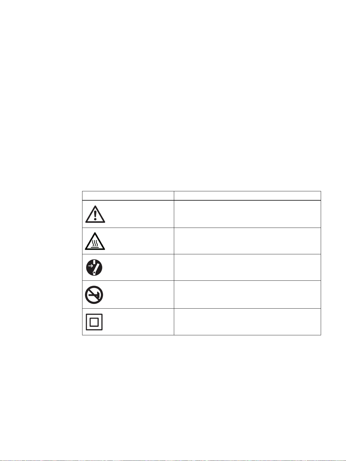
①
Pressure gauge block, single-acting
②
Valve
③
Yoke / actuator yoke
④
Single-acting positioner in non-flameproof aluminum enclosure
⑤
Actuator
①
Part-turn actuator
②
Pressure gauge block, double-acting
③
Double-acting positioner in Makrolon enclosure
3.2 Structure
Various add-on extensions are available for linear actuators:
● IEC 60534-6-1 (NAMUR)
● Integrated addition to ARCA
● Integrated addition to SAMSON in non-flameproof aluminum enclosure
Figure 3-1 Positioner attached to a single-acting linear actuator
Figure 3-2 Positioner attached to double-acting part-turn actuator
SIPART PS2 with and without HART
20 Operating Instructions, 09/2014, A5E00074631-12
Page 23
Description
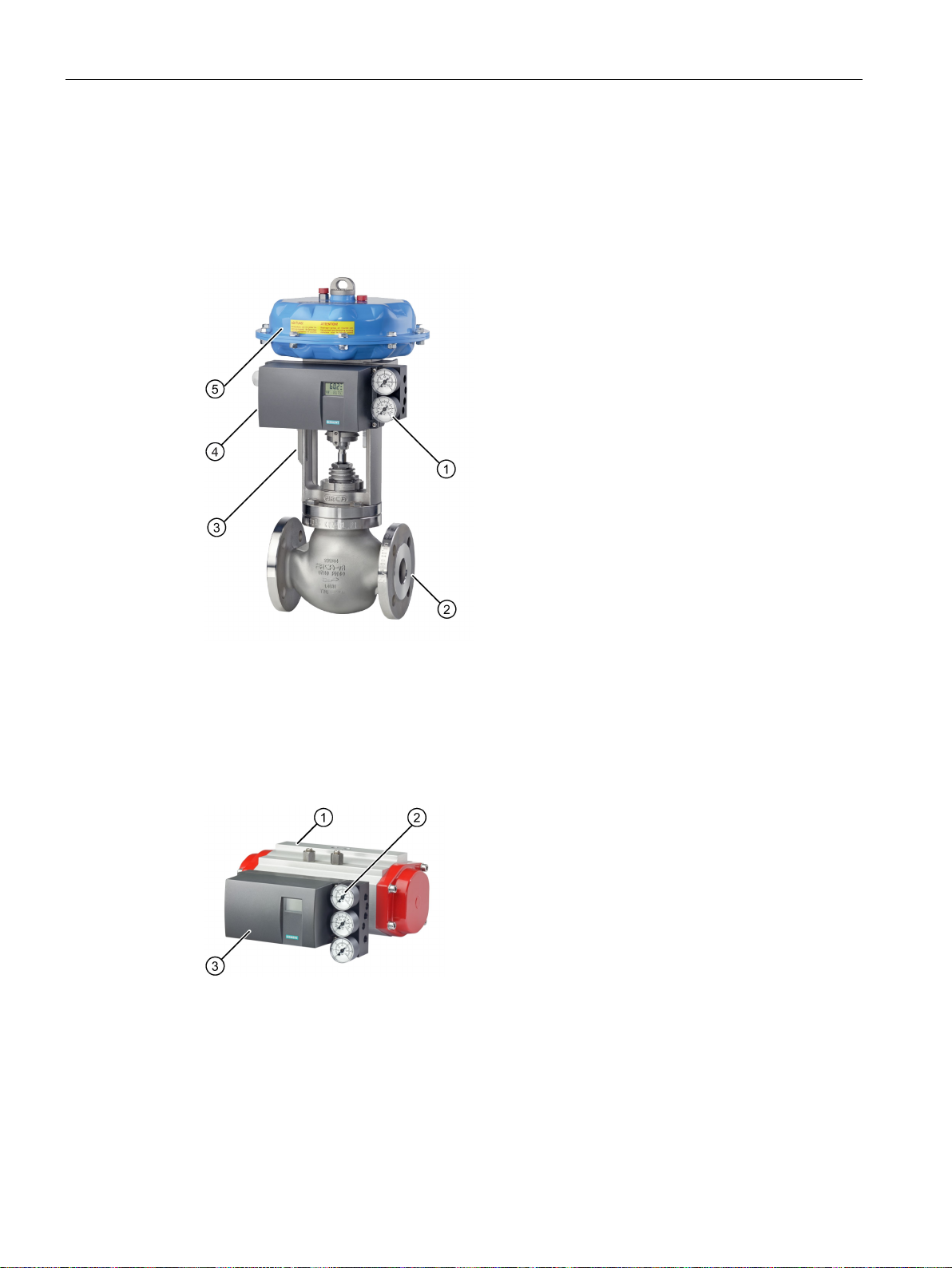
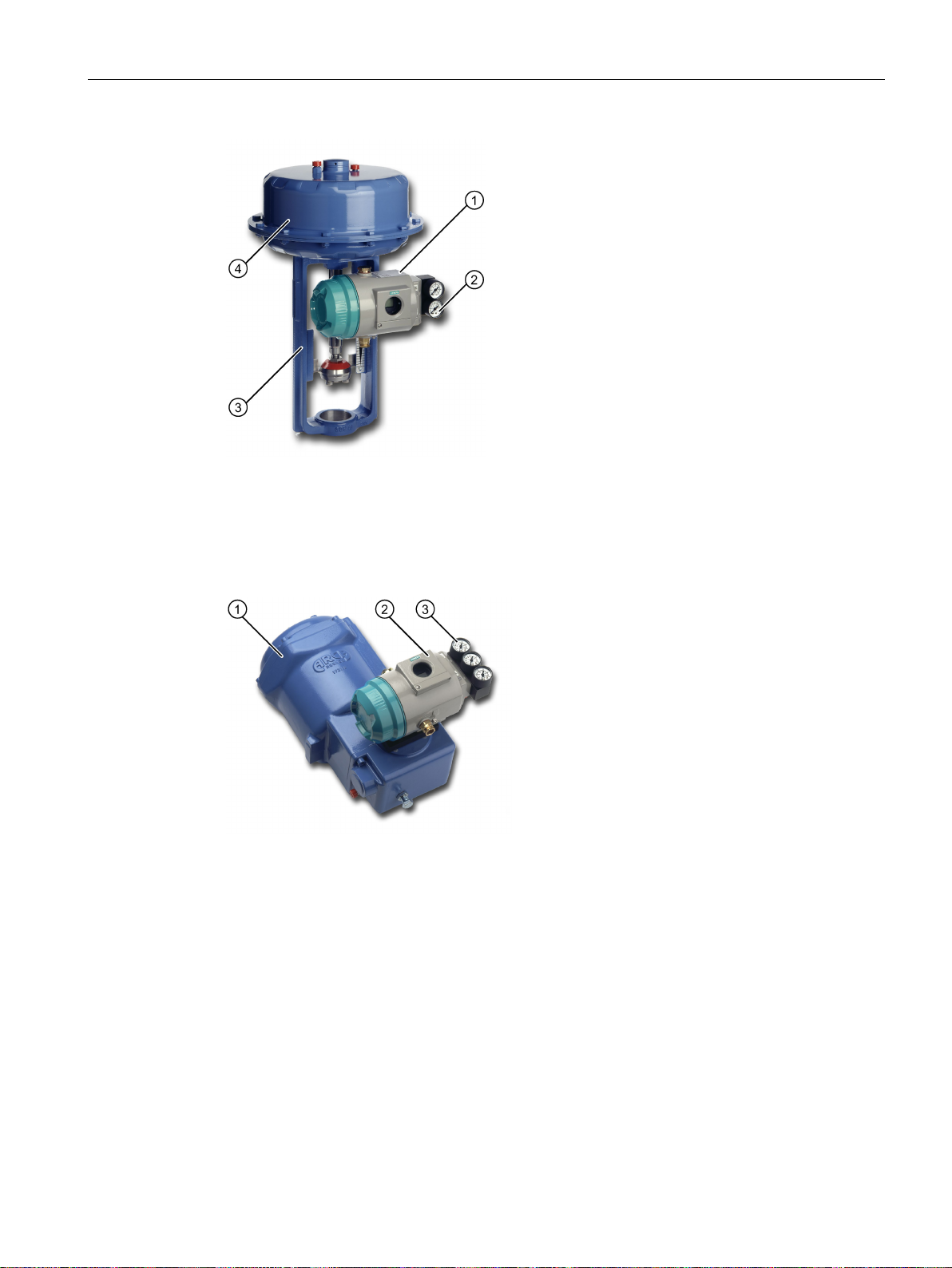
①
Single-acting positioner in flameproof aluminum enclosure
②
Pressure gauge block, single-acting
③
Yoke / actuator yoke
④
Actuator
①
Part-turn actuator
②
Double-acting positioner in flameproof aluminum enclosure
③
Pressure gauge block, double-acting
3.2 Structure
Figure 3-3 Positioner in flameproof aluminum enclosure attached to linear actuator
Figure 3-4 Positioner in flameproof aluminum enclosure attached to part-turn actuator
SIPART PS2 with and without HART
Operating Instructions, 09/2014, A5E00074631-12
21
Page 24
Description
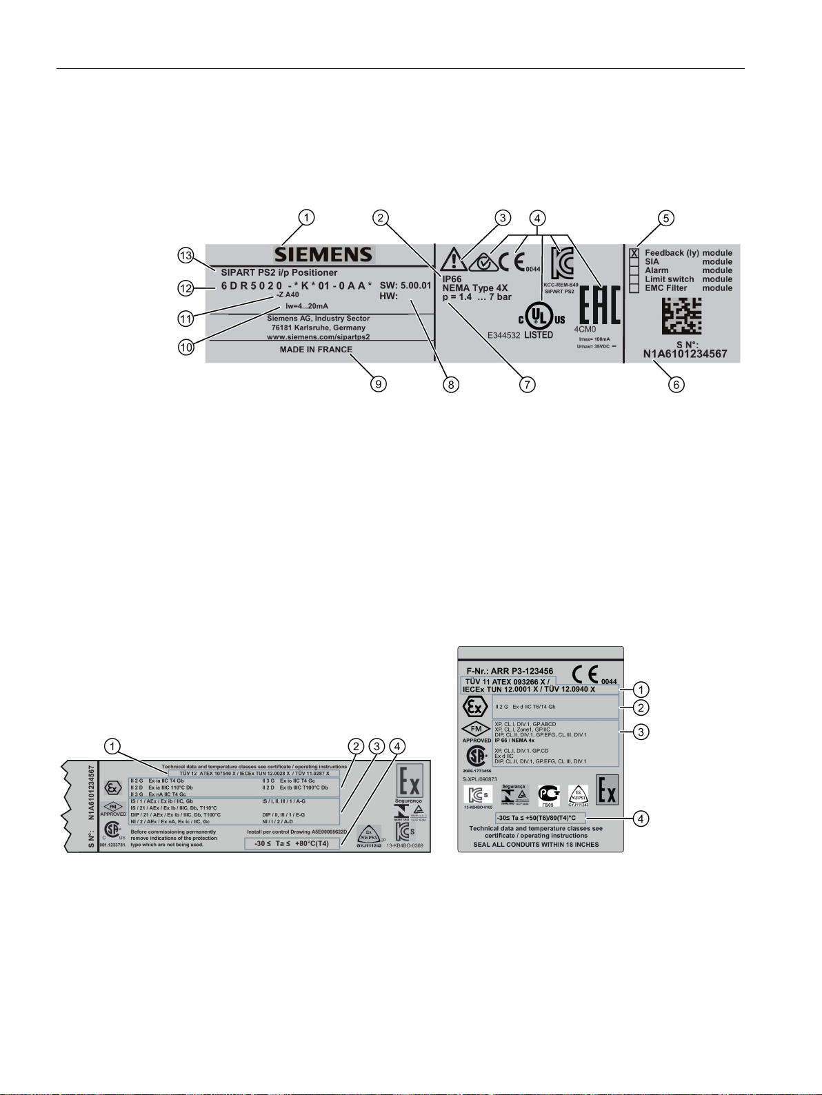
3.2.2
Nameplate layout
Layout of the nameplate
①
Manufacturer
⑧
Software/hardware version
②
Safety class
⑨
Place of manufacture
③
Consult operating instructions
⑩
Auxiliary power
④
Conformity with country-specific directives
⑪
Ordering supplement (Order code)
⑤
⑫
⑥
Serial number
⑬
Product name
⑦
Auxiliary power (supply air PZ)
Layout of Ex nameplate
①
Approvals
③
FM/CSA marking for hazardous area
②
④
area of the corresponding temperature class
3.2 Structure
Built-in option module
Figure 3-5 Nameplate layout, example
Article number
ATEX/IECEx marking for hazardous area
Figure 3-6 Ex nameplate layout, example
SIPART PS2 with and without HART
22 Operating Instructions, 09/2014, A5E00074631-12
Permitted ambient temperature for the hazardous
Page 25

Description
Explanation of Ex information
①
④
ture class)
②
Type of protection
⑤
Device protection level
③
Group (gas, dust)
3.2 Structure
Category for operating range
Figure 3-7 Explanation of Ex information
Maximum surface temperature (tempera-
SIPART PS2 with and without HART
Operating Instructions, 09/2014, A5E00074631-12
23
Page 26
Description
3.3
Device components
3.3.1
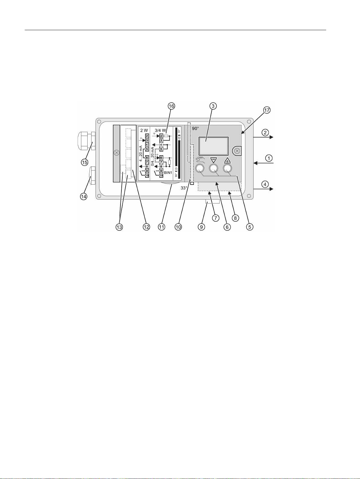
Overview of device components
①
Input: Supply air PZ
⑩
Transmission ratio selector 2)
②
Output: Actuating pressure Y1
⑪
Friction clutch adjustment wheel
③
Display
⑫
Basic electronics
④
Output: Actuating pressure Y2 1)
⑬
Connecting terminals of option modules
⑤
Buttons
⑭
Dummy plug
⑥
Restrictor Y1 for single-acting actuators
⑮
Cable gland
⑦
Restrictor Y1 for double-acting actuators
⑯
Wiring diagram on module cover
⑧
Restrictor Y2 for double-acting actuators
⑰
Purging air selector
⑨
Exhaust air outlet with a sound absorber
for double-acting actuators
only possible when positioner is open
3.3 Device components
1)
2)
Figure 3-8 View of positioner with cover open
SIPART PS2 with and without HART
24 Operating Instructions, 09/2014, A5E00074631-12
Page 27
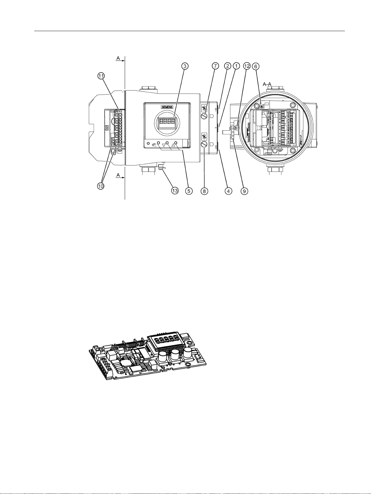
Description
①
Input: Supply air PZ
⑧
Restrictor Y2 1)
②
Output: Actuating pressure Y1
⑨
Friction clutch adjustment wheel
③
Display
⑩
Connecting terminals of option modules
④
Output: Actuating pressure Y2 1)
⑪
Connecting terminals of basic electronics
⑤
Buttons
⑫
Safety catch
⑥
Transmission ratio selector 2)
⑬
Ground terminal
⑦
Restrictor Y1
1) for double-acting actuators
only possible when positioner is open
3.3.2
Basic electronics
3.3 Device components
2)
Figure 3-9 View of positioner in flameproof enclosure, cover opened
Figure 3-10 Basic electronics, schematic representation
The basic electronics contains:
● CPU
● Memory
● Analog-to-digital converter
SIPART PS2 with and without HART
Operating Instructions, 09/2014, A5E00074631-12
25
Page 28

Description
3.4
Mode of operation
Control loop
N
See also
3.4 Mode of operation
● Display
● Buttons
● Terminal strips to connect the option module to the basic electronics
The electropneumatic positioner forms a control loop with the pneumatic actuator:
● The actual value x represents the position of the actuator spindle for linear actuators or
the position of the actuator shaft for part-turn actuators.
● The control value w represents the positioning current of a closed-loop controller or a
manual control station from 0/4 to 20 mA.
The stroke or rotary movement of the actuator is transferred to a potentiometer using
suitable attachments, positioner shaft and a backlash-free, switchable gear drive, and then to
the analog input of the microcontroller.
The current position can also be forwarded to the positioner using an external sensor. A
on-Contacting Position Sensor (NCS) is used to record the stroke or rotary angle directly
on the actuator.
The microcontroller:
● Corrects the angle error of the shaft pick-up if necessary.
● Compares the potentiometer voltage as actual value x with the setpoint w. The setpoint w
is connected to terminals 6 and 7 by means of PROFIBUS communication.
● Calculates the manipulated variable increments ±∆y.
The piezo-controlled inlet or exhaust air valve is opened depending on the magnitude and
direction of the control deviation (x-w). The actuator volume integrates the controller
increment for the actuating pressure y which is proportional to the drive rod or the drive
shaft. This controller increment change the actuating pressure until the control deviation
becomes zero.
Pneumatic actuators are available in single and double-acting versions. In a single-acting
version, only one pressure chamber is ventilated and depressurized. The pressure
developed works against a spring. In a double-acting version, two pressure chambers work
against each other. Ventilating the volume of one chamber simultaneously depressurizes the
volume of the other.
Block circuit diagram for single-acting or double-acting actuators (Page 28)
SIPART PS2 with and without HART
26 Operating Instructions, 09/2014, A5E00074631-12
Page 29
Description
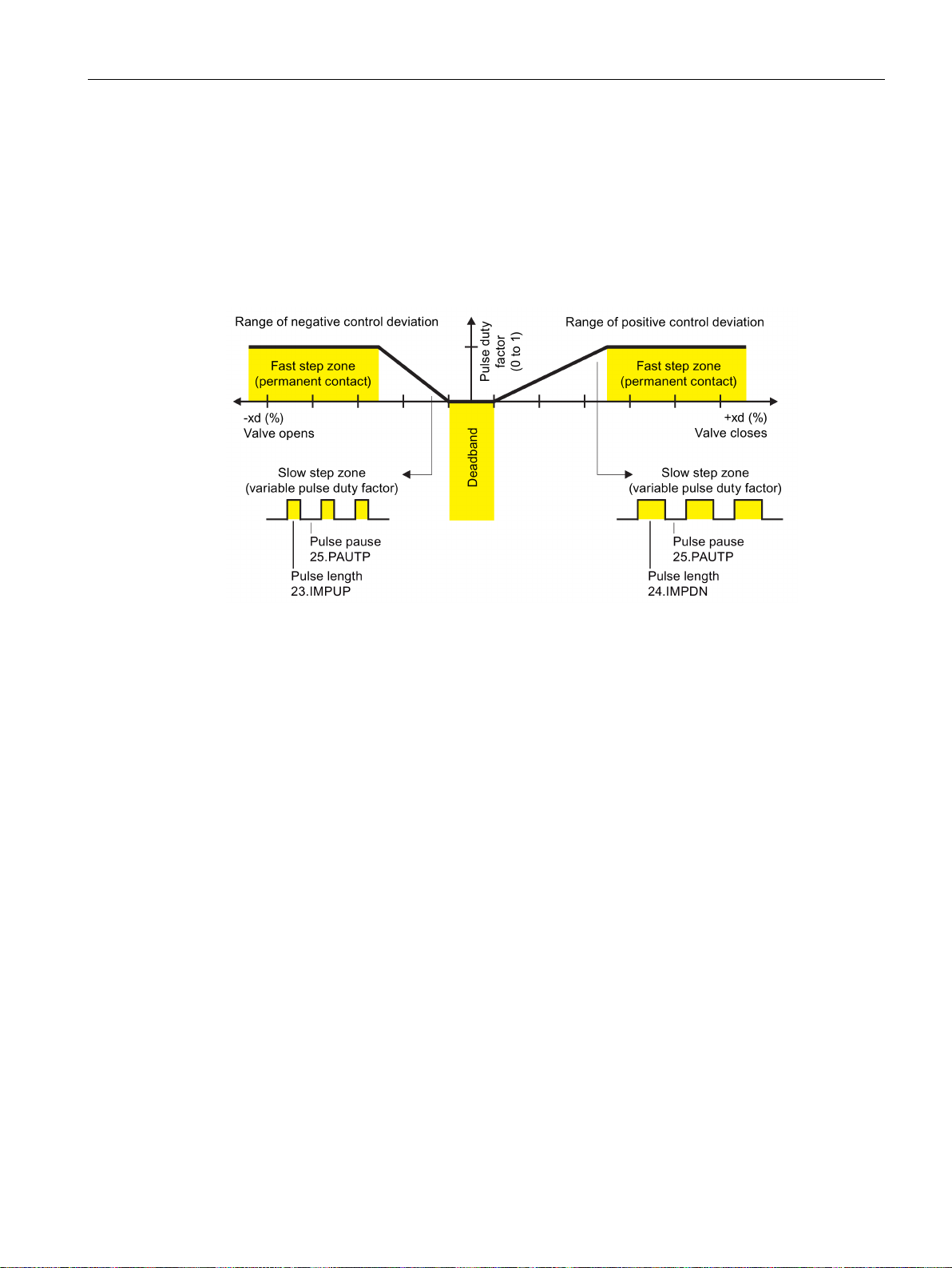
3.4.1
Control algorithm
3.4 Mode of operation
The control algorithm is an adaptive, predictive five-point controller.
In case of large control deviations, the valves are controlled using permanent contact. This
takes place in the so-called fast step zone.
In case of medium control deviations, valves are controlled using pulse-length modulated
pulses. This takes place in the so-called slow step zone.
Figure 3-11 Functional principle of five-point controller
Small control deviations do not send control pulses in the zone. This takes place in the socalled adaptive deadband. The deadband adaptation and the continuous adaptation of
minimum pulse lengths in "Automatic" mode ensure the best possible control accuracy with
the smallest number of operating cycles. The start parameters are determined during the
initialization phase and stored in the non-volatile memory. The most important start
parameters are:
● The real actuator travel with end positions
● Travel times
● The deadband size
The number of fault messages, changes in direction, and the number of strokes are
continuously determined during operation and saved every 15 minutes. You can read and
document these parameters using communication programs such as PDM and AMS. By
comparing the old values with the current ones, you can draw conclusions about the wear
and tear of the valve. You can use the diagnostics function for this.
SIPART PS2 with and without HART
Operating Instructions, 09/2014, A5E00074631-12
27
Page 30
Description
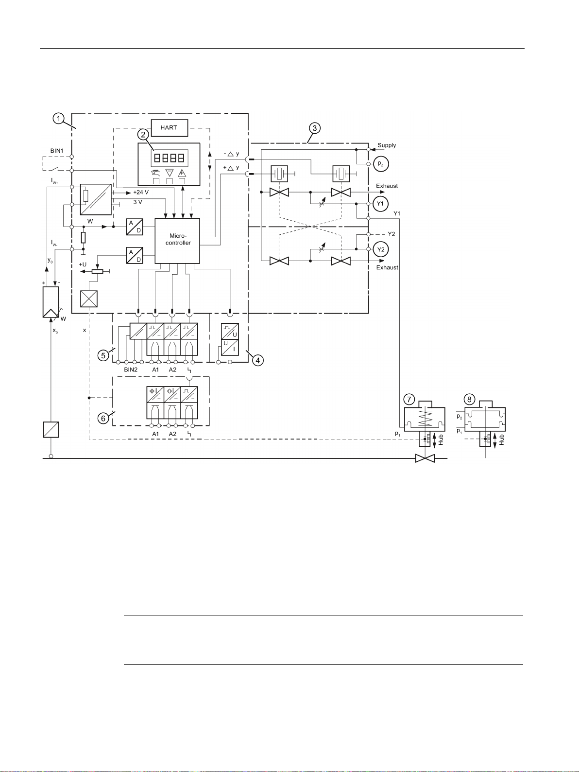
3.4.2
Block circuit diagram for single-acting or double-acting actuators
①
Basic electronics with microcontroller and input circuit
②
Control pad with display and buttons
③
Single-acting or double-acting pneumatic block
④
Position feedback module for positioner
⑤
Alarm module for three alarm outputs and one binary input
⑥
SIA module (slot initiator alarm module)
⑦
Spring-loaded pneumatic actuator (single-acting)
⑧
Pneumatic actuator (double-acting)
Note
Alarm module and SIA module
Alarm module
3.4 Mode of operation
Figure 3-12 Block circuit diagram for the electropneumatic positioner, functional diagram
SIPART PS2 with and without HART
28 Operating Instructions, 09/2014, A5E00074631-12
⑤ and SIA module ⑥ can only be alternatively used.
Page 31

Description
3.4.3
Mode of operation of the HART function
Note
Priority of operation / failure of power supply
•
•
Function
3.4.4
HART system configuration
Overview
3.4 Mode of operation
Operation at the positioner has priority over specifications from the HART communicator.
Failure of the auxiliary power to the positioner also interrupts communications.
The positioner is also available with built-in HART functionality. The HART protocol allows
you to communicate with your device using a HART communicator, PC, or programming
unit. You can do the following with your device:
● Convenient configuration
● Store configurations
● Call up diagnostic data
● Show online measured values
Communication takes place as frequency modulation on the existing signal lines for the
control values of 4 to 20 mA.
The positioner is integrated into the following parameter assignment tools:
● HART communicator
● PDM (Process Device Manager)
● AMS (Asset Management System)
The positioner can be used in a number of system configurations:
● Stand-alone, supplied with the required auxiliary power supply; communication with
supplementary units (handheld), for example
● As part of a complex system environment, e.g. SIMATIC S7
SIPART PS2 with and without HART
Operating Instructions, 09/2014, A5E00074631-12
29
Page 32

Description
System communication
3.4.5
SIMATIC PDM
3.4 Mode of operation
Communication is via the HART protocol, using:
● HART Communicator (load 230 ... 1100 Ω)
● PC with HART modem, on which appropriate software is installed, e.g. SIMATIC PDM
(load 230 ... 500 Ω)
● Control system which can communicate via the HART protocol, e.g. SIMATIC PCS7
Figure 3-13 Typical system configurations
SIMATIC PDM is a software package for configuring, parameter assignment, commissioning,
diagnostics and maintenance of this device and other process devices.
SIMATIC PDM offers simple monitoring of process values, alarms, and device status
information.
SIMATIC PDM allows the process device data to be:
● displayed
● set
● modified
● saved
● diagnosed
● checked for plausibility
● managed
● simulated
SIPART PS2 with and without HART
30 Operating Instructions, 09/2014, A5E00074631-12
Page 33

4
4.1
Basic safety instructions
WARNING
Unsuitable device for the hazardous area
WARNING
High operating force with pneumatic actuators
WARNING
Lever for position detection
WARNING
Impermissible accessories and spare parts
Danger of explosion.
• Only use equipment that is approved for use in the intended hazardous area and
labelled accordingly.
Risk of injury when working on control valves due to the high operating force of the
pneumatic actuator.
• Please observe the corresponding safety instructions for the pneumatic actuator in use.
Danger of crushing and shearing with mounting kits which use a lever for position detection.
During commissioning and ongoing operation, severing or squeezing of limbs could occur
as a result of the lever. Risk of injury when working on control valves due to the high
operating force of the pneumatic actuator.
• Do not reach into the range of motion of the lever following mounting of the positioner
and mounting kit.
Danger of explosion in areas subject to explosion hazard.
• Only use original accessories or original spare parts.
• Observe all relevant installation and safety instructions described in the instructions for
the device or enclosed with the accessory or spare part.
SIPART PS2 with and without HART
Operating Instructions, 09/2014, A5E00074631-12
31
Page 34

Installing/mounting
WARNING
It is possible to damage the cover gasket
WARNING
Open cable inlet or incorrect cable gland
See also
WARNING
Exceeded maximum ambient or process media temperature
CAUTION
Unsuitable compressed air
4.1 Basic safety instructions
If the cover gasket is not positioned correctly in the groove of the base plate, it could be
damaged when the cover is mounted and screwed tight.
• Therefore make sure that the gasket is seated correctly.
Danger of explosion in hazardous areas.
• Close the cable inlets for the electrical connections. Only use cable glands or plugs
which are approved for the relevant type of protection.
Construction (Page 243)
Danger of explosion in hazardous areas.
Device damage.
• Make sure that the maximum permissible ambient and process media temperatures of
the device are not exceeded. Refer to the information in Chapter "Technical data
(Page 241)".
Device damage. As a general rule, the positioner must only be operated with dry and clean
compressed air.
• Use the customary water separators and filters. An additional dryer is required in
extreme cases.
• Use dryers, especially if you operate the positioner at low ambient temperatures.
SIPART PS2 with and without HART
32 Operating Instructions, 09/2014, A5E00074631-12
Page 35

Installing/mounting
CAUTION
Please note the following before working on the control valve and when attaching the
positioner
– Commission the positioner.
WARNING
Mechanical impact energy
NOTICE
Torque with NPT screwed gland
4.1 Basic safety instructions
Danger of injury.
• Prior to working on the control valve, you must move the control valve into a completely
pressureless state. Proceed as follows:
– Depressurize the actuator chambers.
– Switch off the supply air PZ.
– Lock the valve in its position.
• Make sure that the valve has reached the pressureless state.
• If you interrupt the pneumatic auxiliary power to the positioner, the pressureless position
may only be reached after a certain waiting time.
• When mounting, observe the following sequence imperatively to avoid injuries or
mechanical damage to the positioner/mounting kit:
– Mount the positioner mechanically.
– Connect the electrical auxiliary power supply.
– Connect the pneumatic auxiliary power supply.
In order to ensure the degree of protection of the housing (IP66), protect the housing
versions of the positioners listed here from mechanical impact energy:
• 6DR5..3; not greater than 2 Joule
• 6DR5..0; not greater than 1 Joule
• 6DR5..1 with inspection window; not greater than 1 Joule
Device damage. The maximum torque of the cable gland must not be exceeded.
• To avoid damage to the device, you must hold the NPT adapter in place while screwing
the NPT gland into the NPT adapter. Refer to the section "Technical specifications >
Construction (Page 243)" for the torque value.
SIPART PS2 with and without HART
Operating Instructions, 09/2014, A5E00074631-12
33
Page 36

Installing/mounting
4.1.1
Proper mounting
NOTICE
Incorrect mounting
CAUTION
Loss of degree of protection
4.2
Mounting the linear actuator
Requirements
4.2 Mounting the linear actuator
The device can be damaged, destroyed, or its functionality impaired through improper
mounting.
• Before installing ensure there is no visible damage to the device.
• Make sure that process connectors are clean, and suitable gaskets and glands are
used.
• Mount the device using suitable tools. Refer to the information in Technical data
(Page 241) for installation torque requirements.
Damage to device if the enclosure is open or not properly closed. The degree of protection
specified on the nameplate or in Chapter "Technical data (Page 241)" is no longer
guaranteed.
• Make sure that the device is securely closed.
There are linear actuators for standard mounting in accordance with IEC 60534 and for
integrated pneumatic mounting. Use the reduced mounting kit 6DR4004-8VK for actuators
with integrated mounting.
SIPART PS2 with and without HART
34 Operating Instructions, 09/2014, A5E00074631-12
Page 37

Installing/mounting
Actuator type
Required installation components
⑧
⑧
⑦
4.2 Mounting the linear actuator
This section describes how to connect the positioner to the actuator using the mounting kit
6DR4004-8V. You require different installation parts of this mounting kit depending on the
selected actuator type. All installation parts listed in the following table are included in the
product package of the mounting kit 6DR4004-8V. The mounting kit is suitable for a stroke of
3 to 35 mm. In the event of a larger range of stroke, you require the accessory "Lever for
strokes greater than 35 to 130 mm", article number 6DR4004-8L, in addition to the mounting
set 6DR4004-8V. Keep the suitable installation parts ready:
Yoke with fin
Yoke with
plane surface
• Hexagon bolt
• Washer
• Spring lock washer
• Four hexagon bolts
• Washer
• Spring lock washer
⑪
⑪
⑩
⑩
SIPART PS2 with and without HART
Operating Instructions, 09/2014, A5E00074631-12
Yoke with
columns
• Two U–bolts
• Four hexagon nuts
• Washer
• Spring lock washer
⑪
⑳
⑩
35
Page 38

Installing/mounting
Procedure
"Linear actuator IEC 60534 (3 to 35 mm)" mounting kit 6DR4004-8V and 6DR4004-8L
Sr. No. *)
Quantity
Name
Note
①
IEC 60534
surface
②
③
④
⑤
⑥
8L is additionally required for ranges of stroke
> 35 mm to 130 mm (not included in the scope of delivery).
⑧
tions > Construction (Page 243)"
⑩
⑫
⑬
⑭
⑮
⑯
⑰
⑱
⑳
4.2 Mounting the linear actuator
⑦
⑨
⑪
⑲
1 NAMUR mounting bracket
1 Pick-up bracket Guides the pulley with the carrier pin and rotates the lever arm.
2 Clamping piece Installs the pick-up bracket on the actuator spindle
1 Carrier pin
1 Pulley
1 Lever For the range of stroke from 3 mm to 35 mm
2 U–bolts Only for actuators with columns
4 Hexagon bolt M8x20 DIN 933–A2
2 Hexagon bolt M8x16 DIN 933–A2, torque see the section "Technical specifica-
6 Spring lock washer A8 - DIN 127–A2
6 Washer B8.4 - DIN 125–A2
2 Washer B6.4 - DIN 125–A2
1 Spring VD-115E 0.70 x 11.3 x 32.7 x 3.5
1 Spring lock washer A6 - DIN 137A–A2
1 Lock washer 3.2 - DIN 6799–A2
3 Spring lock washer A6 - DIN 127–A2
3 Socket cap screw M6x25 DIN 7984–A2
1 Hexagon nut M6 - DIN 934–A4
1 Square nut M6 - DIN 557–A4
4 Hexagon nut M8 - DIN 934–A4
Standardized connection point for mount with fin, column or plane
Installation with pulley ⑤ on lever ⑥
Installation with carrier pin ④ on lever ⑥
The lever 6DR4004–
*)
the serial numbers refer to the images of the description of the installation steps below.
SIPART PS2 with and without HART
36 Operating Instructions, 09/2014, A5E00074631-12
Page 39

Installing/mounting
4.2 Mounting the linear actuator
1. Install the clamping pieces ③ on the actuator spindle. Use spring lock washers ⑯ and
socket cap screws
⑰ for this purpose.
2. Slide the pick-up bracket
Figure 4-1 Pick-up bracket
3. Set the necessary length.
4. Tighten the screws
⑰ so that you can still shift the pick-up bracket ②.
② into the milled recesses of the clamping pieces ③.
5. Fix the pre-installed carrier pin
washer
Figure 4-2 Lever with carrier pin
6. Set the stroke value. Use the stroke value specified on the nameplate of the actuator for
this purpose. If none of the values on the lever scale matches the stroke value of the
actuator, select the next higher value on the scale. Position the pin center
corresponding value of the scale. If you need the value of actuator travel after
initialization in mm: ensure that the configured stroke value matches the value of the
"3.YWAY" parameter.
⑭ and hexagon nut ⑱ for this purpose.
④ to the lever ⑥. Use the flat washer ⑫, spring lock
④ on the
SIPART PS2 with and without HART
Operating Instructions, 09/2014, A5E00074631-12
37
Page 40

Installing/mounting
4.2 Mounting the linear actuator
7. Install the following components on the lever ⑥: Socket cap screw ⑰, spring lock
washer
Figure 4-3 Components on the lever
8. Push the pre-installed lever ⑥ up to the endstop on the positioner shaft. Fasten the lever
⑯, flat washer ⑫, square nut ⑲.
⑥ with socket cap screw ⑰.
9. Install the mounting bracket
2 spring lock washers
Figure 4-4 Positioner, base plate
⑩ and 2 flat washers ⑪ for this purpose.
① at the rear side of the positioner. Use 2 hexagon bolts ⑨,
SIPART PS2 with and without HART
38 Operating Instructions, 09/2014, A5E00074631-12
Page 41

Installing/mounting
flameproof
Note
Height adjustment of the positioner
When you fasten the positioner on the yoke, the following applies to its height adjustment:
1.
2.
3.
4.2 Mounting the linear actuator
Figure 4-5 Positioner in the
10.Select the row of holes. The selection of the row of holes depends on the yoke width of
the actuator. Select the row of holes in such a way that the carrier pin
pick-up bracket
the clamping pieces
② near the spindle. Ensure that the pick-up bracket ② does not touch
③.
enclosure, base plate
④ meshes with the
11.Keep the positioner and the fastening bracket on the actuator. Ensure that the carrier pin
④ is guided inside the pick-up bracket ②.
12.Tighten the pick-up bracket
13.Fasten the positioner on the yoke. Use the installation parts suitable for the
corresponding actuator.
Set the height of the positioner in such a way that the horizontal lever position is near
the center of the stroke.
Orient yourself by the lever scale of the actuator.
If symmetrical mounting is not possible, you must always ensure that the horizontal
lever position is maintained within the range of stroke.
②.
SIPART PS2 with and without HART
Operating Instructions, 09/2014, A5E00074631-12
39
Page 42

Installing/mounting
4.3
Mounting the part-turn actuator
Requirements
Procedure
"Part-turn actuator" mounting kit 6DR4004–8D
Sr.
No.
*)
Q
ua
nti
ty
Name
Note
①
②
④
⑤
⑥
⑦
⑧
⑨
screw
⑩
screw
wrench
*)
flameproof enclosure.
4.3 Mounting the part-turn actuator
You require an actuator-specific VDI/VDE 3845 mount to install the positioner on a part-turn
actuator.
1 Coupling wheel Installation on positioner shaft
1 Carrier Installation on stump of actuator shaft
③
1 Multiple plate
8 Scale Different divisions
2 Pointer mark Reference arrow for scale
Mount Actuator-specific, VDI/VDE 3845
4 Hexagon bolt M6x12 DIN 933, torque see the section "Technical specifications > Construction (Page 243)"
4 Lock washer S6
1 Socket cap
Display of the position, consisting of scale ⑤ and pointer mark ⑥
M6x16 DIN 84
⑪
1 Machinist's
The serial numbers refer to the images describing the assembly procedure for a part-turn actuator, with and without
SIPART PS2 with and without HART
40 Operating Instructions, 09/2014, A5E00074631-12
1 Washer 6.4 DIN 125
1 Hexagon
socket-head
For coupling wheel
For hexagon socket-head screw ⑪
Page 43

Installing/mounting
Note
Coupling wheel
Instead of the plastic coupling wheel
(article number TGX: 16300
4.3 Mounting the part-turn actuator
1. Rest the actuator-specific VDI/VDE 3845 mount ⑥ on the rear side of the positioner.
Tighten the mount using the hexagon bolts
⑦ and lock washers ⑧.
2. Stick the pointer mark
⑤ on the mount. Position the pointer mark at the center of the
centering hole.
Pointer mark
Pointer mark, flameproof enclosure
3. Push the coupling wheel ① or the stainless steel coupling up to the endstop on the
positioner shaft. Then retract the coupling wheel or the stainless steel coupling by
approximately 1 mm. Tighten the hexagon socket-head screw
⑪ using the machinist's
wrench provided. Maximum tightening torque = 1 Nm. If you are using the stainless steel
coupling, omit the next step.
①, it is possible to use a stainless steel coupling
-1556).
Coupling wheel
Coupling wheel, flameproof enclosure
SIPART PS2 with and without HART
Operating Instructions, 09/2014, A5E00074631-12
41
Page 44

Installing/mounting
4.3 Mounting the part-turn actuator
4. Place the carrier ② on the stump of the actuator shaft. Tighten the carrier ② using the
socket cap screw
⑨ and the washer ⑩.
Figure 4-6 Carrier
5. With the coupling wheel: Place the positioner and the mount on the actuator carefully.
The pin of the coupling wheel
① must fit in the carrier ② when you do this.
With the stainless steel coupling: Place the positioner and the mount on the actuator
carefully. Place the stainless steel coupling on the stump of the actuator's positioner
shaft.
Orientation of mount
Orientation of mount, flameproof enclosure
6. Align the positioner/mount at the center of the actuator.
7. Tighten the positioner/mount unit.
8. Initialize the positioner.
9. After commissioning, drive the positioner to the end position.
SIPART PS2 with and without HART
42 Operating Instructions, 09/2014, A5E00074631-12
Page 45

Installing/mounting
H = height of shaft butt
①
Fixing level of positioner on mount
②
Part-turn actuator
4.3 Mounting the part-turn actuator
10.Stick the scale ④ with the direction of rotation or the swivel range on the coupling wheel
①. The stickers with scale are self-adhesive.
Adhesive label with scale
Adhesive label with scale, flameproof enclosure
SIPART PS2 with and without HART
Operating Instructions, 09/2014, A5E00074631-12
Figure 4-7 Dimensions of mount in accordance with VDI/VDE 3845 (depends on actuator)
43
Page 46

Installing/mounting
See also
4.4
Using the positioner in a humid environment
Introduction
Favorable and unfavorable mounting positions
Additional measures to prevent liquids from seeping through
4.4 Using the positioner in a humid environment
Preparing part-turn actuators for commissioning (Page 131)
The positioner enclosure provides IP66 protection with an intended installation position. It
can therefore be operated in a moist or wet environment in the mounting positions shown
below. Do not use other mounting positions since it would then be possible for liquids, fluff,
fibers or dusts to enter the device via the exhaust openings.
Avoid the unfavorable mounting positions:
● To prevent fluids seeping through during normal operation of the device, e.g. through
exhaust air openings.
● Otherwise the display becomes poorly legible.
Figure 4-8 Favorable and unfavorable mounting positions
Take additional measures to prevent liquids from seeping through if the conditions force you
to operate the positioner in an unfavorable mounting position.
Additional measures required to prevent liquids from seeping through depend on the
selected mounting position. You may also require:
● Gland with sealing ring, e.g. FESTO: CK - 1 / 4-PK-6
● Approximately 20 to 30 cm plastic hose, e.g. FESTO: PUN - 8 x 1.25 SW
● Cable tie; the number and the length depend on the local conditions.
SIPART PS2 with and without HART
44 Operating Instructions, 09/2014, A5E00074631-12
Page 47

Installing/mounting
Procedure
Procedure for installing the plastic hose on the gland
4.5
Positioners subjected to fast acceleration or strong vibration
4.5 Positioners subjected to fast acceleration or strong vibration
1. Install the casing such that rain water or condensate running along the pipes can be
drained before the terminal strip of the positioner.
2. Check the seals of electrical connections for perfect fitting.
3. Check the seal in the enclosure cover for damage and contaminations. Clean and/or
replace if required.
4. Install the positioner such that the sintered bronze attenuator at the bottom side of the
enclosure points downwards in the vertical mounting position. If this is not possible,
replace the attenuator with a suitable gland with a plastic hose.
1. Unscrew the sintered bronze attenuator from the exhaust air opening at the bottom side
of the enclosure.
2. Screw in the aforementioned gland into the exhaust air opening.
3. Install the aforementioned plastic hose into the gland and check whether it fits firmly.
4. Fasten the plastic hose with a cable tie onto the control valve such that the opening
points downwards.
5. Ensure that the plastic hose does not have any kinks and the exhaust air flows out
without any hindrance.
The electropneumatic positioner has an gear latch for the friction clutch and for the
transmission ratio selector.
Strong acceleration forces act on control valves that are subjected to heavy mechanical
loads, e.g. breakaway valves, strongly shaking or vibrating valves, as well as in case of
"vapor shocks". These forces may be much higher than the specified data. This may cause
the friction clutch to move in extreme cases.
The positioner is equipped with an gear latch for the friction clutch to counter these extreme
cases. The setting of the transmission ratio selector can also be locked. Using the accessory
"NCS sensor for non contact position detection", it is possible to mount the controller unit a
certain distance away, e.g. on a mounting pipe or similar.
The locking procedure is illustrated and described below.
SIPART PS2 with and without HART
Operating Instructions, 09/2014, A5E00074631-12
45
Page 48

Installing/mounting
Overview diagram
NOTICE
Wrong registration of the rotary or part-turn movement
①
Gear latch
⑥
Friction clutch
②
Locking transmission ratio to 33°
⑦
Friction clutch latch
③
Neutral position
⑧
Locking friction clutch
④
Locking transmission ratio to 90°
⑨
Release friction clutch
⑤
Transmission ratio selector
4.5 Positioners subjected to fast acceleration or strong vibration
A different setting of the transmission ratio selector and the gear latch results in a
hysteresis in position registration. The hysteresis in position registration can result in
unstable control behavior of the higher level control loop.
• Make sure the transmission ratio selector
value, either to 33° or to 90°.
⑤ and the gear latch ① are set to the same
Figure 4-9 Locking friction clutch and transmission ratio
SIPART PS2 with and without HART
46 Operating Instructions, 09/2014, A5E00074631-12
Page 49

Installing/mounting
Requirements
Procedure
NOTICE
The following is applicable for the "flameproof enclosure" version:
Note
Changing the setting of the transmission ratio selector
The setting of the transmission ratio selector
gear latch
4.5 Positioners subjected to fast acceleration or strong vibration
● The positioner is mounted.
● You know whether the transmission ratio is to be set to 33° or 90°.
● The positioner has been commissioned successfully, i.e. initialization was completed with
"FINISH".
• A friction clutch is provided on the outside of the positioner shaft. Change the work area
using this friction clutch, legend number
(Page 24)".
• Do not open the flameproof enclosure of the positioner in explosion-prone atmospheres.
Fix the setting acquired by initialization as follows:
⑨ in "Overview of device components
1. Make sure the gear latch
and 90°.
2. Make sure the transmission ratio selector
3. Fix the transmission ratio with the gear latch
approx. 4 mm wide screwdriver until the gear latch
transmission ratio to 33°
transmission ratio is locked.
① is in neutral position ③. The neutral position is between 33°
⑤ is in the correct position.
①. Turn the gear latch ① with a standard
① locks. Turning right locks the
②. Turning left locks the transmission ratio to 90°④. The
⑤ can only be changed effectively if the
① is in the neutral position ③.
4. To fix the friction clutch ⑥, insert a standard approx. 4 mm wide screwdriver in the
friction clutch gear latch
5. Use the screwdriver to turn the friction clutch gear latch
The friction clutch
⑦ (does not apply to device version "Flameproof enclosure").
⑦ anticlockwise until it engages.
⑥ is fixed (does not apply to device version "Flameproof enclosure").
SIPART PS2 with and without HART
Operating Instructions, 09/2014, A5E00074631-12
47
Page 50

Installing/mounting
4.6
External position detection
WARNING
External position detection system
4.7
Installing option modules
4.7.1
General information on installing option modules
WARNING
Unsuitable device for the hazardous area
4.6 External position detection
Versions with flameproof enclosures may not be operated with an external position
detection system.
The aforementioned measures are not adequate in some applications. For example,
continuous and strong vibrations, high or too low ambient temperatures and nuclear
radiation.
The position detection system and the controller unit are mounted separately for these
applications. A universal component is available for this purpose. It is suitable for part-turn
and linear actuators. You will require the following:
● An external position detection system with the article number C73451-A430-D78
comprising a positioner enclosure with an integrated friction clutch, potentiometer as well
as different blanking plugs and seals.
● Or a contactless explosion-proof non contacting system (e.g.6DR4004-6N).
● A positioner
● A three-pole cable to connect components.
● An EMC filter module with the article number C73451-A430–D23 is provided in a set
along with cable clamps and M20 cable glands.
The EMC filter module is always used for the controller unit whenever an external position
detection system is used instead of the internal sensor. An external position detection
system is, for example, a potentiometer with a 10 kΩ resistance or an NCS.
Danger of explosion.
• Only use equipment that is approved for use in the intended hazardous area and
labelled accordingly.
SIPART PS2 with and without HART
48 Operating Instructions, 09/2014, A5E00074631-12
Page 51

Installing/mounting
4.7.1.1
Installing optional modules in the standard and intrinsically safe version
4.7 Installing option modules
The following option modules are available for the positioner in the standard and intrinsically
safe version:
● Position feedback module
● Alarm module
● SIA module
● Mechanical limit switch module
● EMC filter module
SIPART PS2 with and without HART
Operating Instructions, 09/2014, A5E00074631-12
49
Page 52

Installing/mounting
Overview diagram: Installing optional modules in the standard and intrinsically safe version
①
Module cover
⑪
Position feedback module
②
Fixing screws module cover
⑫
Alarm module
③
⑬
nameplate
④
⑭
module
⑤
Pneumatic block
⑮
Insulating cover
⑥
Special screw
⑯
Basic electronics
⑦
⑰
system
4.7 Installing option modules
SIPART PS2 with and without HART
50 Operating Instructions, 09/2014, A5E00074631-12
Fixing screws basic electronics
Actuating disk bearings
Transmission ratio selector
Warning label on the side opposite the
SIA module or mechanical limit switch
Ribbon cable/connector for fitted poten-
tiometer or external position detection
Page 53

Installing/mounting
⑧
⑱
switch module
⑨
⑲
feedback module
⑩
Adapter
⑳
Wiring diagram
General procedure for optional modules in the standard and intrinsically safe version
Note
Untimely wear
The module cover is fastened using self
and one screw for the valve.
•
See also
4.7 Installing option modules
Friction clutch adjustment wheel
Nameplate
Figure 4-10 Installing the optional modules in the standard and intrinsically safe version
Ribbon cable/connector for alarm mod-
ule, SIA module or mechanical limit
Ribbon cable/connector for position
1. Open the positioner. Unscrew the four fixing screws of the enclosure cover.
2. Disconnect the power supply lines or de-energize them.
3. Remove the module cover
4. Install the optional modules as described in the corresponding sections for the individual
optional modules.
5. Now start with the assembly. Install the module cover
counter clockwise until they noticeably engage in the thread pitch. The module cover
protects and locks the optional modules mechanically.
①. To do this, unscrew the two screws ②.
①. To this end, turn the screws ②
-tapping screws, one screw for the base plate
Proceed as described here in order to avoid premature wear of the base plate and
valve.
Carefully tighten both screws ② in a clockwise direction.
6. Continue to assemble the positioner by executing steps 3 to 1 in reverse order.
Position feedback module (Page 56)
Alarm module (Page 57)
Slot initiator alarm module (Page 59)
Mechanical limit switch module (Page 62)
EMC filter module (Page 66)
SIPART PS2 with and without HART
Operating Instructions, 09/2014, A5E00074631-12
51
Page 54

Installing/mounting
4.7.1.2
Installing the optional modules in the "flameproof enclosure" version
Introduction
DANGER
Risk of explosion
4.7 Installing option modules
The following option modules are available for the positioner in the flameproof enclosure:
● Position feedback module
● Alarm module
● EMC filter module
You must fulfill the following conditions before supplying auxiliary power to the positioner in
potentially hazardous areas:
• The installed electronic unit has been approved.
• The enclosure of the positioner is closed.
• The duct openings for electronic connections must be closed. Only use the Ex d certified
cable entries or sealing plugs.
• You must install an ignition trap if you use a "conduit piping system". The maximum
distance between the ignition trap and the positioner enclosure is 46 cm or 18".
SIPART PS2 with and without HART
52 Operating Instructions, 09/2014, A5E00074631-12
Page 55

Installing/mounting
Overview diagram: Installing the optional modules in the "flameproof enclosure" version
①
Module cover
⑪
Transmission ratio selector
②
Fixing screws module cover
⑫
Fixing screws adapter
③
external position detection system
⑬
④
Ribbon cable/connector for alarm module
⑭
Friction clutch adjustment wheel
⑤
Ribbon cable/connector for position feedback module
⑮
Feedback shaft
⑥
Basic electronics
⑯
Ring gear
⑦
Alarm module
⑰
Enclosure
⑧
Position feedback module
⑱
Feedback lever bracket with pin
⑨
Screw cap
⑲
Pin (feedback lever bracket)
⑩
Adapter
4.7 Installing option modules
Ribbon cable/connector for fitted potentiometer or
SIPART PS2 with and without HART
Operating Instructions, 09/2014, A5E00074631-12
Safety catch
53
Page 56

Installing/mounting
General procedure for optional modules in the "flameproof enclosure" version
Note
Damage to the ring gear
The ring gear consists of two washers fastened staggered to each other. This offset
ensures that path detection is backlash
•
NOTICE
Displaced O-rings
4.7 Installing option modules
Figure 4-11 Installing the optional modules in the "flameproof enclosure" version
1. Disconnect the power supply lines or de-energize them.
2. Open the safety catch
3. Unscrew the screw cap
4. Completely dismount the positioner from the actuator.
5. The positioner comes with a ring gear
interlock and ensure backlash-free position feedback. To ensure backlash-free position
feedback make sure to remove the adapter
⑮ at the positioner until the pin (feedback lever bracket) ⑲ below the adapter
shaft
shows in the direction of removal. You determine the position of the pin by looking into
the enclosure below the adapter. Now, the pin can be easily removed from the ring gear
⑯.
Do not change this offset mechanically.
6. Unlatch the four fixing screws ⑫.
7. Completely remove the adapter
⑬.
⑨.
⑯ and a pin (feedback lever bracket) ⑲ which
⑩ carefully. To this end, turn the feedback
-free.
⑩ from the enclosure ⑰.
There are several O-rings between adapter ⑩ and enclosure ⑰. These O-rings may
come off during removal.
• Carefully remove the adapter. Make sure the O-rings do not get lost during removal.
8. Remove the module cover ①. Unlatch both screws ② using a screwdriver.
9. Install the optional modules as described in the corresponding sections for the individual
optional modules.
SIPART PS2 with and without HART
54 Operating Instructions, 09/2014, A5E00074631-12
Page 57

Installing/mounting
Note
Untimely wear
The module cover is fastened using a self-tapping
•
not
See also
4.7 Installing option modules
10.Now start with the assembly. Install the module cover ①. To this end, turn the screws ②
counter clockwise until they noticeably engage in the thread pitch. The module cover
protects and locks the optional modules mechanically.
screw for the valve.
Proceed as described here in order to avoid premature wear of the valve.
Carefully tighten both screws ② in a clockwise direction.
11.Continue to assemble the positioner by executing steps 7 to 5 in reverse order. Check
whether the position of the O-rings is correct. Make sure no loose items in the enclosure
interfere with the assembly.
12.Now check carefully whether the feedback shaft
If you feel resistance, do
continue to turn but turn the feedback shaft ⑮ back again to
⑮ can be smoothly turned by 360°.
the point of removal, making sure to remember the previously performed steps.
13.Once you have completed all previous steps successfully, continue by performing steps 4
to 1 in reverse order.
Position feedback module (Page 56)
Alarm module (Page 57)
SIPART PS2 with and without HART
Operating Instructions, 09/2014, A5E00074631-12
55
Page 58

Installing/mounting
4.7.2
Position feedback module
Function
Device features
Requirements
Procedure
4.7 Installing option modules
● The optional position feedback module indicates the current position as a two-wire signal
with the travel range I
from the basic device.
● The current position is indicated only after successful initialization.
● Operational faults are signaled by a fault current of 3.6 mA.
= 4 to 20 mA. The position feedback module is electrically isolated
y
Figure 4-12 Position feedback module
The position feedback module is:
● Single channel
● Potentially separated from the basic device.
You are familiar with the general procedure described in the section "General information on
installing option modules (Page 48)".
1. Slide the position feedback module up to the endstop in the lower bay of the rack.
2. Connect the module to the basic electronics. For this purpose, use the 6-pin flat ribbon
cable provided.
SIPART PS2 with and without HART
56 Operating Instructions, 09/2014, A5E00074631-12
Page 59

Installing/mounting
4.7.3
Alarm module
Function
Device features
4.7 Installing option modules
The alarm module triggers fault messages and alarms via three binary outputs. The
message function is based on the change in the signal status:
● If the signal status is "HIGH", there is no alarm message and the binary inputs are
conductive.
● If the signal status is "LOW", the module reports an alarm by shutting down binary
outputs using a high-resistance.
● Operational faults are signaled at a high-resistance output. Set the following parameters
to activate and configure the output of alarms and fault messages:
– "AFCT" - Alarm function
– "A1" - Response threshold, alarm 1
– "A2" - Response threshold, alarm 2
– "FCT" - Function fault message output
– "TIM" - Monitoring time
– "LIM" - Response threshold
Apart from binary outputs, the alarm module has a binary input BIN2. Depending on the
selected parameters, it is used to block the actuator or to move it to its end position.
Configure the suitable settings on parameter "BIN2".
Figure 4-13 Alarm module
SIPART PS2 with and without HART
Operating Instructions, 09/2014, A5E00074631-12
57
Page 60

Installing/mounting
Requirements
Procedure for installing the alarm module
4.7 Installing option modules
The alarm module has the following features:
● Available in two versions.
– Explosion-proof version for connecting to a switching amplifier in conformity with
EN 60947-5-6.
– Non-explosion-proof version for connecting to power sources having a maximum of
35 V.
● Three binary outputs. Binary inputs are potentially separated from the basic configuration
and from each other.
● The binary input BIN2 has two inputs. Both inputs are implemented as logical OR
combination.
– Input 1 at terminals 11/12: is electrically isolated, and is triggered by an active signal.
– Input 2 at terminals 21/22: is not electrically isolated, and is triggered by a passive NO
contact.
You are familiar with the general procedure described in the section "General information on
installing option modules (Page 48)".
1. Slide the alarm module into the rack below the basic electronics . Ensure that you slide it
up to the endstop.
2. Connect the module to the basic electronics. For this purpose, use the 8-pin flat ribbon
cable provided.
SIPART PS2 with and without HART
58 Operating Instructions, 09/2014, A5E00074631-12
Page 61

Installing/mounting
4.7.4
Slot initiator alarm module
Function
Device features
①
Actuating disk bearings
④
Upper actuating disk for limit L1, terminals 41/42
②
Special screw
⑤
Lower actuating disk for limit L2, terminals 51/52
③
Pin ⑥ Binary outputs
Requirements
4.7 Installing option modules
If the standard controller requires electrically independent limit value messages, the slotted
initiator alarm module with slotted initiators is used instead of the alarm module.
● A binary output is used to display a collective fault message. Compare with the function of
the alarm module. The floating binary output is implemented as an automatic fault
indicating semiconductor output.
● The other two binary outputs are used to signal the two limits L1 and L2 which can be
adjusted mechanically using slotted initiators. Both these binary outputs are electrically
independent from the remaining electronic unit.
Figure 4-14 SIA module
The slotted initiator alarm module, SIA module for short, consists of three binary outputs ⑥.
You are familiar with the general procedure described in the section "Installing optional
modules in the standard and intrinsically safe version (Page 49)".
SIPART PS2 with and without HART
Operating Instructions, 09/2014, A5E00074631-12
59
Page 62

Installing/mounting
Procedure for installing the slot initiator alarm module
torque of 2 Nm
Note
Pin in the actuating disk bearing
A pin
1.
2.
not
4.7 Installing option modules
1. Disconnect all electrical connections of the basic electronics.
2. Loosen the two fixing screws of the basic electronics.
3. Remove the basic electronics.
4. Insert the SIA module from the top up to the upper printed circuit board guide of the rack.
5. Slide the SIA module in the printed circuit board of the rack approximately 3 mm to the
right.
6. Screw in the special screw
the special screw
② with a
② through the SIA module into the positioner shaft. Tighten
.
③ is pressed in the actuating disk bearing①.
Align pin ③ before placing the adjustment screw ② into the actuating disk bearing
①.
Rotate the actuating disk bearing ① and the special screw ② simultaneously so that
the pin
7. Set the limits L1 and L2 as described in the section "Setting the limits of the slotted
initiator alarm module (Page 61)".
8. An insulating cover is provided over the SIA module. Place the insulating cover on one
side under the basic electronics seat on the module cover. The recesses of the insulating
cover must fit in the corresponding webs of the module cover.
9. Place the insulating cover on the SIA module by bending the module covers carefully.
10.Place the basic electronics onto the four holders.
11.Fix the basic electronics using both the fixing screws.
12.Reestablish all electrical connections between the basic electronics and the option
modules. Connect the basic electronics and the option modules to the ribbon cables
provided. Connect the basic electronics and the potentiometer to the potentiometer cable.
③ is inserted into the special screw ②.
13.Using both the screws, fasten the module cover provided. Do
14.Select the labels that already exist on the standard version of the module cover from the
SIPART PS2 with and without HART
60 Operating Instructions, 09/2014, A5E00074631-12
use the standard
module cover.
label set provided. Affix the selected labels on the installed module cover as per the
standard version.
Page 63

Installing/mounting
4.7.4.1
Setting the limits of the slotted initiator alarm module
Procedure: Determining the switch status of the slotted initiators
Procedure: Setting the L1 and L2 limits
Note
Adjusting the actuating disk
The actuating disks
their unintentional movement during operation. You can achieve an easier and finer
adjustment by reducing stiction temporarily.
•
4.7 Installing option modules
You will require a suitable display device to determine the switch status. For example, use
the initiator tester type 2 / Ex from Pepperl + Fuchs.
1. Connect the display device to the following terminals of the SIA module:
– 41 and 42
– 51 and 52
2. Read the switch status of slotted initiators.
The serial numbers in the following text refer to the image in the section "Slot initiator alarm
module (Page 59)". Proceed as follows to set the limits:
1. Move the actuator to the first desired mechanical position.
2. Adjust the upper actuating disk
changes. Set a high-low or a low-high switchover as follows:
– Rotate the actuating disc
switching point.
④ manually until the output signal at terminals 41 and 42
④ beyond the switching point until you reach the next
3. Move the actuator to the second desired mechanical position.
4. Adjust the lower actuating disk
changes. Set a high-low or a low-high switchover as follows:
– Rotate the actuating disc
switching point.
⑤ manually until the output signal at terminals 51 and 52
⑤ beyond the switching point until you reach the next
④ and ⑤ are relatively difficult to move. This design prevents
Move the actuator to and fro while simultaneously holding the actuating disks ④
⑤.
and
SIPART PS2 with and without HART
Operating Instructions, 09/2014, A5E00074631-12
61
Page 64

Installing/mounting
4.7.5
Mechanical limit switch module
Requirements
Procedure for installing the mechanical limit switch module
①
Actuating disk bearings
④
Upper actuating disk for limit L1, terminals 41/42
②
Special screw
⑤
Lower actuating disk for limit L2, terminals 51/52
③
Pin
4.7 Installing option modules
You are familiar with the procedure described in the section "Installing optional modules in
the standard and intrinsically safe version (Page 49)".
Figure 4-15 Mechanical limit switch module
1. Disconnect all electrical connections of the basic electronics.
2. Loosen the two fixing screws of the basic electronics.
3. Remove the basic electronics.
4. Insert the mechanical limit switch module from the top up to the upper printed circuit
board guide of the module rack.
5. Slide the mechanical limit switch module in the printed circuit board of the module rack
approximately 3 mm towards right.
SIPART PS2 with and without HART
62 Operating Instructions, 09/2014, A5E00074631-12
Page 65

Installing/mounting
torque of 2 Nm
Note
Pin in the actuating disk bearing
A pin
1.
2.
Note
Protective conductor connector
A protective conductor connector is not required for safety reasons and therefore
provided.
See also
4.7 Installing option modules
6. Screw in the special screw ② through the mechanical limit switch module into the
positioner shaft. Tighten the special screw
② with a
.
③ is pressed in the actuating disk bearing①.
Align pin ③ before placing the adjustment screw ② into the actuating disk bearing
①.
Rotate the actuating disk bearing ① and the special screw ② simultaneously so that
the pin
7. Set the limits L1 and L2 as described in the section "Setting the limits of the mechanical
limit switch module (Page 64)".
8. An insulating cover is provided over the mechanical limit switch module. Place the
insulating cover on one side under the basic electronics seat on the walls of the rack. The
recesses of the insulating cover must fit in the corresponding webs of the container wall.
9. Place the insulating cover on the mechanical limit switch module by bending the walls of
the rack carefully.
③ is inserted into the special screw ②.
10.Place the basic electronics onto the four holders.
11.Fix the basic electronics using both the fixing screws.
12.Reestablish all electrical connections between the basic electronics and the option
modules. Connect the basic electronics and the option modules to the ribbon cables
provided. Connect the basic electronics and the potentiometer to the potentiometer cable.
13.Using both the screws, fasten the module cover provided. Do not use the standard
module cover.
14.Select the labels that already exist on the standard version of the module cover from the
label set provided. Affix the selected labels on the installed module cover as per the
standard version.
15.Establish all electrical connections.
is not
Label set for limit contact module (Page 65)
SIPART PS2 with and without HART
Operating Instructions, 09/2014, A5E00074631-12
63
Page 66

Installing/mounting
4.7.5.1
Setting the limits of the mechanical limit switch module
Setting the L1 and L2 limits
Note
Adjusting the actuating disk
The actuating disks
their unintentional movement during operation. You can achieve an easier and finer
adjustment by reducing stiction temporarily.
•
See also
4.7 Installing option modules
To set the limits proceed as follows. The consecutive numbers refer to "Figure 4-15
Mechanical limit switch module (Page 62)".
1. Move the actuator to the first desired mechanical position.
2. Adjust the upper actuating disk
changes. Set a high-low or a low-high switchover as follows:
– Rotate the actuating disc beyond the switching point until you reach the next switching
point.
3. Move the actuator to the second desired mechanical position.
4. Adjust the lower actuating disk
changes. Set a high-low or a low-high switchover as follows:
– Rotate the actuating disc beyond the switching point until you reach the next switching
point.
④ manually until the output signal at terminals 41 and 42
⑤ manually until the output signal at terminals 51 and 52
④ and ⑤ are relatively difficult to move. This design prevents
Move the actuator to and fro while simultaneously holding the actuating disks ④
⑤.
and
Mechanical limit switch module (Page 62)
SIPART PS2 with and without HART
64 Operating Instructions, 09/2014, A5E00074631-12
Page 67

Installing/mounting
4.7.5.2
Label set for limit contact module
See also
4.7 Installing option modules
Fasten the included warning label on the side across from the nameplate. There are different
warning labels depending on the enclosure material, as described below.
Figure 4-16 Warning label for a device with a Makrolon enclosure
Figure 4-17 Warning label for a device with an aluminum enclosure
Figure 4-18 Warning label for a device with a stainless steel enclosure
Warning symbols on the device (Page 15)
SIPART PS2 with and without HART
Operating Instructions, 09/2014, A5E00074631-12
65
Page 68

Installing/mounting
4.7.6
EMC filter module
Requirements
Function
Device features
4.7 Installing option modules
● You have an EMC filter module, article number C73451-A430-D23.
● The module cover is removed.
● Any already installed optional module has been removed.
A description of how to remove the module cover and install the optional modules is provided
in the section "General information on installing option modules (Page 48)"
You will require the EMC filter module if you use an external position sensor on the
positioner, e.g. a potentiometer or a non-contacting sensor. The EMC filter module forms the
interface between external position sensors and the basic electronics of the positioner. This
module protects the positioner from electromagnetic effects.
● EMC protection
● Connection to basic electronics
● Connecting terminals for an external potentiometer
Figure 4-19 EMC filter module
SIPART PS2 with and without HART
66 Operating Instructions, 09/2014, A5E00074631-12
Page 69

Installing/mounting
Procedure for installing the EMC filter module
①
EMC filter module terminals
⑤
Basic electronics
②
Positioner
⑥
Screw
③
Yellow wheel for locking the position detection
⑦
EMC filter module C73451-A430-D23
④
or ribbon cable connector of EMC filter module
4.7 Installing option modules
Ribbon cable connector of fitted potentiometer,
Figure 4-20 Installation EMC filter module
1. You have performed the steps described in the section "General information on installing
option modules (Page 48)".
2. Unplug the ribbon cable connector
electronics
3. Remove the basic electronics
that fix the basic electronics to the pneumatic block.
4. Loosen the screw
5. Insert the connector of the ribbon cable (A) into the slot as shown below.
6. Secure the EMC filter module using the screw
⑤.
⑥ in the connection area of the positioner.
④ to the fitted potentiometer from the basic
⑤ from the positioner. To this end, remove the two screws
⑥ loosened in the fourth step.
7. Fit the basic electronics
8. Insert the ribbon cable connector
electronics.
9. Fasten the module cover. Make sure that the ribbon cable is not trapped.
10.Proceed with the corresponding steps in the section "General information on installing
option modules (Page 48)".
SIPART PS2 with and without HART
Operating Instructions, 09/2014, A5E00074631-12
⑤ back into the positioner.
④ of the EMC filter module onto the positioner basic
67
Page 70

Installing/mounting
See also
4.7.7
Accessories
Pressure gauge block
Y1
Actuating pressure
PZ
Supply air
Y2
Actuating pressure
Fixing the pressure gauge block
4.7 Installing option modules
Scope of delivery of external position detection system (Page 270)
Scope of delivery EMC filter module (Page 271)
Pressure gauge blocks that are available as accessories are illustrated below. The gauges
display measured values for the actuating pressure and supply air. The image to the left
shows the pressure gauge block for single-acting actuators. The image to the right shows
the pressure gauge block for double-acting actuators.
The pressure gauge block is fixed onto the lateral pneumatic connection of the positioner
using the screws provided. Use the provided O-rings as sealing elements.
SIPART PS2 with and without HART
68 Operating Instructions, 09/2014, A5E00074631-12
Page 71

5
5.1
Basic safety instructions
WARNING
Improper power supply
WARNING
Unsafe extra-low voltage
WARNING
Connecting device in energized state
Exceptions
WARNING
Lack of equipotential bonding
Exception
Danger of explosion in hazardous areas as result of incorrect power supply, e.g. using
direct current instead of alternating current.
• Connect the device in accordance with the specified power supply and signal circuits.
The relevant specifications can be found in the certificates, in Chapter "Technical data
(Page 241)" or on the nameplate.
Danger of explosion in hazardous areas due to voltage flashover.
• Connect the device to an extra-low voltage with safe isolation (SELV).
Danger of explosion in hazardous areas.
• Connect devices in hazardous areas only in a de-energized state.
:
• Circuits of limited energy may also be connected in the energized state in hazardous
areas.
• Exceptions for type of protection "Non-sparking nA" (Zone 2) are regulated in the
relevant certificate
Danger of explosion through compensating currents or ignition currents through lack of
equipotential bonding.
• Ensure that the device is potentially equalized.
with type of protection "Intrinsic safety Ex i".
SIPART PS2 with and without HART
Operating Instructions, 09/2014, A5E00074631-12
: It may be permissible to omit connection of the equipotential bonding for devices
69
Page 72

Connection
WARNING
Unprotected cable ends
WARNING
Improper laying of shielded cables
WARNING
Unsuitable cables and/or cable glands
WARNING
Incorrect selection of type of protection
5.1 Basic safety instructions
Danger of explosion through unprotected cable ends in hazardous areas.
• Protect unused cable ends in accordance with IEC/EN 60079-14.
Danger of explosion through compensating currents between hazardous area and the nonhazardous area.
• Only ground shielded cables that run into the hazardous area at one end.
• If grounding is required at both ends, use an equipotential bonding conductor.
Danger of explosion in hazardous areas.
• Only use suitable cables and cable glands complying with the requirements specified in
Chapter "Technical data (Page 241)".
• Tighten the cable glands in accordance with the torques specified in Chapter "Technical
data (Page 241)".
• When replacing cable glands use only cable glands of the same type.
• After installation check that the cables are seated firmly.
Danger of explosion in areas subject to explosion hazard.
This device is approved for several types of protection.
1. Decide in favor of one type of protection.
2. Connect the device in accordance with the selected type of protection.
3. In order to avoid incorrect use at a later point, make the types of protection that are not
used permanently unrecognizable on the nameplate.
SIPART PS2 with and without HART
70 Operating Instructions, 09/2014, A5E00074631-12
Page 73

Connection
NOTICE
Condensation in the device
NOTICE
Ambient temperature too high
NOTICE
Standard cable gland/torque
Two-wire mode
NOTICE
Connection of voltage source to current input
5.1 Basic safety instructions
Damage to device through formation of condensation if the temperature difference between
transportation or storage and the mounting location exceeds 20 °C (36 °F).
• Before taking the device into operation let the device adapt for several hours in the new
environment.
Damage to cable sheath.
• At an ambient temperature ≥ 60 °C (140 °F), use heat-resistant cables suitable for an
ambient temperature at least 20 °C (36 °F) higher.
Device damage.
• Owing the reasons pertaining to tightness (IP enclosure rating) and the required tensile
strength, only use the cables having a diameter ≥ 8 mm for standard M20x1.5 cable
gland, or use a suitable seal insert in case of smaller diameters.
• In the NPT version, the positioner is delivered with a coupling. When inserting a counter
piece in the coupling, ensure that the maximum permissible torque of 10 Nm is not
exceeded.
Device damage if a voltage source is connected to the current input Iw (terminals 6 and 7).
• Never connect the current input I
to a voltage source, otherwise the positioner may be
w
destroyed.
• Always use a voltage source with a maximum output current of I = 20 mA.
SIPART PS2 with and without HART
Operating Instructions, 09/2014, A5E00074631-12
71
Page 74

Connection
Note
Improvement of interference immunity
•
•
•
•
•
Electromagnetic compatibility
5.1 Basic safety instructions
Lay signal cables separate from cables with voltages > 60 V.
Use cables with twisted wires.
Avoid getting too close to large electrical process cells.
Use shielded cables to guarantee the full specification according to HART.
Take account of the conditions specified in the technical data for HART communication.
The Macrolon enclosure is metalized from inside to increase the electromagnetic
compatibility (EMC) with respect to high-frequency radiation. The shield is connected to the
threaded bush shown in the following picture such that it is electrically conductive.
Note that this protection is effective only if you connect at least one of these bushes to the
earthed control valves through electrically conductive (bare) attachments.
Shield
Figure 5-1 Base plate
SIPART PS2 with and without HART
72 Operating Instructions, 09/2014, A5E00074631-12
Page 75

Connection
5.2
Electric
5.2.1
Device 6DR5..0/1/2/3-0N or 6DR5..5-0E
Breakdown of the article numbers
Article No.
Selection and ordering data
less steel enclosure, without explosion protection
flameproof
6DR50
2-wire (4 to 20 mA) > without HART >
6DR52
2-, 3-, 4-wire (0/4 to 20 mA) > with HART, explosion-proof >
6DR53
2-, 3-, 4-wire (0/4 to 20 mA) > without HART, not explosion-proof >
6DR5.1
For single-action actuator >
6DR5.2
For double-action actuator >
6DR5..0
Makrolon enclosure >
6DR5.11
Aluminum enclosure, narrow, only single-action >
6DR5..2
Stainless steel enclosure >
6DR5..3
Aluminum enclosure >
6DR5..5
Aluminum enclosure > flameproof
5.2.1.1
Basic electronics with 6DR5..0/1/2/3-0N or 6DR5..5-0E
Connection diagram for article numbers 6DR50.0/1/2/3-0N; 6DR50.5-0E; 6DR51.0/1/2/3-0N;
6DR51.5-0E
①
Basic electronics
③
HART communicator
②
Binary input 1
④
Signal source
5.2 Electric
Table 5- 1
6DR5..0/1/2/3-0N SIPART PS2 electropneumatic positioner in Makrolon, aluminum and stain-
6DR5..5-0E SIPART PS2 electropneumatic positioner in
6DR51 2-wire (4 to 20 mA) > with HART, not explosion-proof >
aluminum enclosure
HART communicator only for 6DR51.0/1/2/3-0N and 6DR51.5-0E
Figure 5-2 Device version 2-wire
SIPART PS2 with and without HART
Operating Instructions, 09/2014, A5E00074631-12
73
Page 76

Connection
Connection diagram for article numbers 6DR52.0/1/2/3-0N; 6DR52.5-0E; 6DR53.0/1/2/3-0N;
6DR53.5-0E
①
Basic electronics
③
HART communicator
②
Binary input 1
④
Signal source
5.2 Electric
HART communicator only for 6DR52.0/1/2/3-0N and 6DR52.5-0E
Figure 5-3 Device version 2-/3-/4-wire, with connection type 2-wire
SIPART PS2 with and without HART
74 Operating Instructions, 09/2014, A5E00074631-12
Page 77

Connection
Connection diagram for article numbers 6DR52.0/1/2/3-0N; 6DR52.5-0E; 6DR53.0/1/2/3-0N;
6DR53.5-0E
①
Basic electronics
④
Power source
②
Binary input 1
⑤
Signal source
③
HART communicator
Split range
5.2 Electric
HART communicator only for 6DR52.0/1/2/3-0N and 6DR52.5-0E
Dotted connection lines: only for three-wire connection
Figure 5-4 Device version 2-/3-/4-wire, with connection type 3-/4-wire
Device 1 and device 2: Positioner 6DR53.0/1/2/3-0N or 6DR53.5-0E
SIPART PS2 with and without HART
Operating Instructions, 09/2014, A5E00074631-12
75
Page 78

Connection
①
Device 1
⑥
Binary input 2
②
Travel range 1
⑦
Total travel range Iy
③
Binary input 1
⑧
Signal source
④
Device 2
⑨
Power source
⑤
Travel range 2
5.2 Electric
Figure 5-5 Series connection of 2 positioners, e.g. split range without Ex
SIPART PS2 with and without HART
76 Operating Instructions, 09/2014, A5E00074631-12
Page 79

Connection
5.2.1.2
Option modules with 6DR5..0/1/2/3-0N or 6DR5..5-0E
Which option module is fitted in which positioner?
without explosion protection
Article number of positioner
Contains the following installed option
module
Article number of installed option module
6DR5...-0N.1.-0.A.
Alarm module
6DR4004-8A
6DR5...-0N.3.-0.A.
Mechanical limit switch module
6DR4004-8K
6DR5...-0N..2-0.A.
EMC filter module
C73453-A430-D23
Position feedback module
6DR4004-8J
EMC filter module
C73453-A430-D23
flameproof enclosure "Ex d"
Article number of positioner
Contains the following installed option
module
Article number of installed option module
6DR5..5-0E.1.-0.A.
Alarm module
6DR4004-8A
6DR5..5-0E..1-0.A.
Position feedback module
6DR4004-8J
5.2 Electric
The article number of the positioner is present on its nameplate. This coded article number
indicates which option module is already installed in your device. The following table lists the
assignment between positioner and installed option module.
Table 5- 2 List of option modules fitted in positioners
6DR5...-0N.2.-0.A. SIA module 6DR4004-8G
6DR5...-0N..1-0.A. Position feedback module 6DR4004-8J
6DR5...-0N..3-0.A.
Table 5- 3 List of option modules fitted in positioners in
The captions of the following connection graphics for the option modules are made up of the
name and article number of the option module.
SIPART PS2 with and without HART
Operating Instructions, 09/2014, A5E00074631-12
77
Page 80

Connection
Alarm module 6DR4004-8A with 6DR5..0/1/2/3-0N or 6DR5..5-0E
①
Alarm module
④
Limit
②
Binary input 2
⑤
Switching amplifier
③
Fault message
⑥
Switching output
Position feedback module 6DR4004-8J with 6DR5..0/1/2/3-0N or 6DR5..5-0E
①
Position feedback module
5.2 Electric
Figure 5-6 Alarm module
Figure 5-7 Position feedback module
SIPART PS2 with and without HART
78 Operating Instructions, 09/2014, A5E00074631-12
Page 81

Connection
SIA module 6DR4004-8G with 6DR5..0/1/2/3-0N
①
SIA module
③
Limit
②
Fault message
④
Switching amplifier
Mechanical limit switch module 6DR4004-8K with 6DR5..0/1/2/3-0N
DANGER
Low-voltage supply
Note
Maximal values for terminals 41/42 and 51/52
The following
No safe separation between the terminals can be guaranteed.
5.2 Electric
Figure 5-8 SIA module
When you supply the module in the non-intrinsically safe version with low voltage, you must
be sure to observe the following safety rules before starting work on the device:
1. Isolate the device from power. Use a circuit breaker positioned near the device to do
this.
2. Make sure that the device cannot be switched back on inadvertently.
3. Make sure the device is truly isolated from power.
maximum values concern only terminals 41, 42, 51, and 52:
SIPART PS2 with and without HART
Operating Instructions, 09/2014, A5E00074631-12
79
Page 82

Connection
Note
To observe before connecting
Before you connect the mechanical limit switch module, observe the following conditions:
•
•
Note
Preparing the cables or stranded wires
1.
2.
①
Mechanical limit switch module
③
Limit
②
Fault message
④
Switching amplifier
Procedure
5.2 Electric
Isolate all wires from power and make sure the device is truly isolated from power.
Construct the cross-sectional area of the connection cables in such a way that it is
appropriate for the permitted current load.
Insulate the cables in such a way that the insulation is flush with the terminal when
plugging in the wires.
Fit ferrules to the ends of stranded wires.
Figure 5-9 Mechanical limit switch module
1. Loosen the screw ① on the transparent cover ②.
2. Pull the transparent cover
3. Tighten every cable in the corresponding terminal.
4. Slide the transparent cover
SIPART PS2 with and without HART
80 Operating Instructions, 09/2014, A5E00074631-12
② up to the front end stop.
② up to the end stop of the basic electronics.
Page 83

Connection
①
Screw
②
Cover
③
Cable tie
5.2.2
Device 6DR5..0/1/2/3-0E/D/F/G/K
5.2.2.1
Breakdown of the article numbers 6DR5..0/1/2/3-0E/D/F/G/K
Breakdown of the article numbers
Article No.
Selection and ordering data
less steel enclosure
6DR50
2-wire (4 to 20 mA) > without HART >
6DR52
2-, 3-, 4-wire (0/4 to 20 mA) > with HART, explosion-proof >
6DR5.1
For single-action actuator >
6DR5.2
For double-action actuator >
6DR5..0
Makrolon enclosure >
6DR5.11
Aluminum enclosure, narrow, only single-action >
6DR5..2
Stainless steel enclosure >
6DR5..3
Aluminum enclosure >
6DR5..0/1/2/3-0E
Type of protection (ATEX/IECEx): intrinsic safety
5.2 Electric
5. Tighten the screw ① of the transparent cover ②.
6. Connect the cables of each switch to the lug of the printed circuit board in pairs. Use the
provided cable ties
③ for this purpose.
Figure 5-10 Connecting the cables
Table 5- 4
6DR5..0/1/2/3 SIPART PS2 electropneumatic positioner in Makrolon, aluminum and stain-
SIPART PS2 with and without HART
Operating Instructions, 09/2014, A5E00074631-12
81
Page 84

Connection
Article No.
Selection and ordering data
enclosure
6DR5..0/1/2/3-0G
Type of protection (ATEX/IECEx): non-incendive
protection by enclosure
WARNING
With intrinsically device version (Ex i)
5.2.2.2
Basic electronics with 6DR5..0/1/2/3-0E/D/F/G/K
Connection diagram for article numbers 6DR50..-0E/D/F/G/K...
①
Non-hazardous area
④
Binary input 1
②
Explosive atmosphere
⑤
Signal source
③
Basic electronics
5.2 Electric
6DR5..0/1/2/3-0D Type of protection (ATEX/IECEx): non-incendive and dust protection by
6DR5..0/1/2/3-0F Type of protection (ATEX/IECEx/FM): intrinsic safety and non-incendive
6DR5..0/1/2/3-0K Type of protection (ATEX/IECEx): intrinsic safety, non-incendive and dust
Risk of explosion in hazardous areas.
For intrinsically safe device versions only the certified circuits may be connected as
auxiliary power supply, control and signal circuits.
• Make sure that the power source of the used circuits is marked as intrinsically safe.
Figure 5-11 Device version 2-wire
SIPART PS2 with and without HART
82 Operating Instructions, 09/2014, A5E00074631-12
Page 85

Connection
Connection diagram for article numbers 6DR52..-0E/D/F/G/K...
①
Non-hazardous area
④
Binary input 1
②
Explosive atmosphere
⑤
HART communicator
③
Basic electronics
⑥
Signal source
5.2 Electric
Figure 5-12 Device version 2-/3-/4-wire, with connection type 2-wire
SIPART PS2 with and without HART
Operating Instructions, 09/2014, A5E00074631-12
83
Page 86

Connection
Connection diagram for article numbers 6DR52..-0E/D/F/G/K...
①
Non-hazardous area
⑤
HART communicator
②
Explosive atmosphere
⑥
Signal source
③
Basic electronics
⑦
Power source
④
Binary input 1
5.2 Electric
Dotted connection lines: only for three-wire connection
Figure 5-13 Device version 2-/3-/4-wire, with connection type 3-/4-wire
SIPART PS2 with and without HART
84 Operating Instructions, 09/2014, A5E00074631-12
Page 87

Connection
Split range
①
Non-hazardous area
⑦
Travel range 2
②
Explosive atmosphere
⑧
Binary input 2
③
Device 1
⑨
Total travel range Iy
④
Travel range 1
⑩
Signal source
⑤
Binary input 1
⑪
Power source
⑥
Device 2
5.2 Electric
Device 1 and device 2: Positioner 6DR52.0; 6DR52.1; 6DR52.2
Figure 5-14 Series connection of 2 positioners, e.g. split range (auxiliary power wired separately),
Ex i
SIPART PS2 with and without HART
Operating Instructions, 09/2014, A5E00074631-12
85
Page 88

Connection
5.2.2.3
Option modules with 6DR5..0/1/2/3-0E/D/F/G/K
Which option module is fitted in which positioner
Article number of positioner
Contains the following installed option
module
Article number of installed option module
6DR5..a-0b.1.-0.A.
Alarm module ATEX and FM/CSA
6DR4004-6A; 6DR4004-7A
6DR5..a-0b.3.-0.A.
Mechanical limit switch module
6DR4004-6K
FM/CSA
FM/CSA
6DR5..a-0b..3-0.A.
EMC filter module
C73453-A430-D23
5.2 Electric
The article number of the positioner is present on its nameplate. This coded article number
indicates which option module is already installed in your device. The following table lists the
assignment between positioner and installed option module.
List of option modules fitted in positioners with the following types of protection:
● Intrinsic safety "Ex i"
● Non-incendive "Ex nA"
● Protection by enclosure "Ex t"
6DR5..a-0b.2.-0.A. SIA module 6DR4004-6G
6DR5..a-0b..1-0.A. Position feedback module ATEX and
6DR5..a-0b..2-0.A. Position feedback module ATEX and
6DR4004-6J; 6DR4004-7J
6DR4004-6J; 6DR4004-7J
a = 0; 1; 2 or 3
b = E, D, F, G, K
The captions of the following connection graphics for the option modules are made up of the
name and article number of the option module.
SIPART PS2 with and without HART
86 Operating Instructions, 09/2014, A5E00074631-12
Page 89

Connection
Alarm modules 6DR4004-6A and -7A with 6DR5..0/1/2/3-0E/D/F/G/K
①
Non-hazardous area
⑤
Fault message
②
Explosive atmosphere
⑥
Limit
③
Alarm module
⑦
Switching amplifier
④
Binary input 2
⑧
Switching output
5.2 Electric
Figure 5-15 Alarm module (Ex i)
SIPART PS2 with and without HART
Operating Instructions, 09/2014, A5E00074631-12
87
Page 90

Connection
Position feedback modules 6DR4004-6J and -7J with 6DR5..0/1/2/3-0E/D/F/G/K
①
Non-hazardous area
③
Position feedback module
②
Explosive atmosphere
④
Feed splitter
SIA module 6DR4004-6G with 6DR5..0/1/2/3-0E/D/F/G/K
①
Non-hazardous area
④
Fault message
②
Explosive atmosphere
⑤
Limit
③
SIA module
⑥
Switching amplifier
5.2 Electric
Figure 5-16 Position feedback module (Ex i)
Figure 5-17 SIA module (Ex i)
SIPART PS2 with and without HART
88 Operating Instructions, 09/2014, A5E00074631-12
Page 91

Connection
Mechanical limit switch module 6DR4004-6K with 6DR5..0/1/2/3-0E/D/F/G/K
①
Non-hazardous area
⑤
Limit
②
Explosive atmosphere
⑥
Isolation amplifier
③
Mechanical limit switch module
⑦
Switching amplifier/isolation amplifier
④
Fault message
Procedure
5.2 Electric
Figure 5-18 Mechanical limit switch module 6DR4004-6K (Ex i)
1. Loosen the screw ① on the transparent cover ②.
2. Pull the transparent cover
3. Tighten every cable in the corresponding terminal.
4. Slide the transparent cover
② up to the front end stop.
② up to the end stop of the basic electronics.
SIPART PS2 with and without HART
Operating Instructions, 09/2014, A5E00074631-12
89
Page 92

Connection
①
Screw
②
Cover
③
Cable tie
5.2 Electric
5. Tighten the screw ① of the transparent cover ②.
6. Connect the cables of each switch to the lug of the printed circuit board in pairs. Use the
provided cable ties
③ for this purpose.
Figure 5-19 Connecting the cables
SIPART PS2 with and without HART
90 Operating Instructions, 09/2014, A5E00074631-12
Page 93

Connection
5.2.3
Connecting NCS to EMC filter module
Requirements
Wiring diagram
①
Positioner (open state)
⑦
Cable clamp
②
Vcc: Yellow
⑧
Screw F3x8
③
Vref: Green
⑨
Cable gland
④
Vpos: Black
⑩
Four-pole NCS cable
⑤
Ground: Brown
⑪
Non Contacting Sensor (NCS)
⑥
EMC filter module C73451-A430-D23
⑫
Cable shielding lug
5.2 Electric
You need the EMC filter module with article number C73451-A430-D23 to connect the NCS
to the positioner. The positioner supplies auxiliary power to the NCS via the EMC filter
module.
Figure 5-20 Example of connecting the NCS to the EMC filter module
SIPART PS2 with and without HART
Operating Instructions, 09/2014, A5E00074631-12
91
Page 94

Connection
Procedure
5.2 Electric
The NCS is equipped with a shielded four-pole cable. Wire this cable to the positioner as
follows:
1. Feed the four-pole NCS cable
type of cable gland depends on the positioner version.
2. Tighten the cable gland
3. Terminate the four-pole NCS cable
diagram.
4. Place the cable clamp
5. Use the screw
ground terminal of the positioner.
6. Grounding:
The rear steel panel of the NCS is inevitably bonded to ground potential of the system by
mounting the console. This ground connection is only functional if there is a lowimpedance connection to ground potential of the system. Ensure this state by measuring
ground resistance. If necessary, ensure proper grounding by means of an additional
cable from the NCS to ground potential.
⑧ to bond the cable shielding lug ⑫ and the cable clamp ⑦ to the
⑦ onto the outer insulation of the four-pole NCS cable ⑩.
⑩ through the union nut and the cable gland. Note: The
⑨.
⑩ in the positioner in accordance with the wiring
SIPART PS2 with and without HART
92 Operating Instructions, 09/2014, A5E00074631-12
Page 95

Connection
5.2.4
Connecting the external position detection system to the EMC filter module
Requirements
Wiring diagram
①
⑧
C73451-A430-D78
②
C73451-A430-D23
⑨
nals
③
tection
⑩
gland
④
filter module
⑪
⑤
Basic electronics
⑫
EMC filter module cable gland
⑥
Screw
⑬
Input signal for positioner
⑦
EMC filter module C73451-A430-D23
5.2 Electric
You need the EMC filter module with article number C73451-A430-D23 for the electrical
connection of an external position detection system, article number C73451-A430-D78, to
the positioner.
Figure 5-21 Connection to positioner
SIPART PS2 with and without HART
Operating Instructions, 09/2014, A5E00074631-12
EMC filter module terminals
Positioner with integral EMC filter module
Yellow wheel for locking the position de-
Ribbon cable connector of fitted potenti-
ometer, or ribbon cable connector of EMC
External position detection system
External position detection system termi-
External position detection system cable
Cable
93
Page 96

Connection
Preparing the positioner
non-
without
Procedure for connecting an external position detection system
See also
5.2 Electric
1. You have performed the steps described in the section "General information on installing
option modules (Page 48)".
2. Unplug the ribbon cable connector
electronics
3. Remove the basic electronics
that fix the basic electronics to the pneumatic block.
4. Loosen screw
5. Insert the connector of the ribbon cable (A) into the slot as shown below.
6. Secure the EMC filter module using the screw
7. Fit the basic electronics
8. Insert the ribbon cable connector
electronics.
9. In
– Stick the supplied nameplate over the nameplate on the external position detection
system
⑤.
⑥ in the connection area of the positioner.
⑤ back into the positioner.
hazardous environment:
⑧.
④ to the fitted potentiometer from the basic
⑤ from the positioner. To this end, remove the two screws
⑥ loosened in the third step.
④ of the EMC filter module onto the positioner basic
– Replace the blue cable gland
Refer to section "Scope of delivery of external position detection system (Page 270)", items
"Nameplate for device version
For further information on fitting of an option module, refer to the operating instructions of the
respective positioner version in section "Installing/mounting > Installing option modules".
⑩ by the supplied gray cable gland.
explosion protection" and "Gray cable gland".
1. Connect the three terminals of the external position detection system ⑨ to the three
terminals of the EMC filter module
2. Tighten the cable glands
⑩ and ⑫.
① using a cable as shown in the wiring diagram.
Installing optional modules in the standard and intrinsically safe version (Page 49)
SIPART PS2 with and without HART
94 Operating Instructions, 09/2014, A5E00074631-12
Page 97

Connection
5.3
Pneumatic
5.3.1
Pneumatic connections
5.3.1.1
Pneumatic connection for 6DR5..0/1/2/3
Structure
①
Actuating pressure Y1 for single and double-acting actuators
②
Positioner shaft
③
Supply air PZ
④
Actuating pressure Y2 for double-acting actuators
⑤
Exhaust air outlet with a sound absorber
5.3.1.2
Integrated pneumatic connection
Structure
5.3 Pneumatic
The pneumatic connections are provided on the right side of the positioner.
Figure 5-22 Pneumatic connection on the standard controller
The following pneumatic connections are provided at the rear side of the basic device for the
integrated attachment for single-acting linear actuators:
● Actuating pressure Y1
● Exhaust air outlet
These connections are sealed with screws when the device is delivered.
The exhaust air outlet is corrosion-resistant for the blanketing of the pick-up room and the
spring chamber with dry instrument air.
SIPART PS2 with and without HART
Operating Instructions, 09/2014, A5E00074631-12
95
Page 98

Connection
①
Actuating pressure Y1
②
Exhaust air outlet
5.3.1.3
Pneumatic connection for 6DR5..5-0E...
Structure
①
Restrictor Y2 *)
⑤
Actuating pressure Y1
②
Restrictor Y1
⑥
Exhaust air outlet
③
Actuating pressure Y2 *)
⑦
Enclosure ventilation (2x)
④
Supply air PZ
*) for double-acting actuators
5.3 Pneumatic
Figure 5-23 Integrated pneumatic connection
The pneumatic connections are provided on the right side of the positioner.
SIPART PS2 with and without HART
96 Operating Instructions, 09/2014, A5E00074631-12
Figure 5-24 Pneumatic connection in the flameproof enclosure
Page 99

Connection
5.3.1.4
Reaction to failure of auxiliary powers
Overview
CAUTION
Before working on the control valve
5.3 Pneumatic
The following overview diagram shows the pneumatic connection versions for different
actuator types, regulating action and safety position after an auxiliary power supply failure.
Note that before working on the control valve, you must first move it to the safety position.
Make sure that the control valve has reached the safety position. If you only interrupt the
pneumatic auxiliary power supply to the positioner, the safety position may in some cases
only be attained after a certain delay period.
SIPART PS2 with and without HART
Operating Instructions, 09/2014, A5E00074631-12
97
Page 100

Connection
5.3 Pneumatic
Figure 5-25 Regulating action of pneumatic connection
SIPART PS2 with and without HART
98 Operating Instructions, 09/2014, A5E00074631-12
 Loading...