

Page 1

SIMODRIVE 611 analog
Start–Up Guide 10.2000 Edition
Transistor PWM Inverters for
AC Feed Drives and
AC Main Spindle Drives
Manufacturer/Service Documentation
Page 2
Overview of Documentation for SIMODRIVE 61 1 analog
General Documentation
SINUMERIK
SIMODRIVE
Catalog
Order Document NC 60
SINUMERIK
SIROTEC
SIMODRIVE
Accessories
Catalog
Accessories and
Equipment for Special–
Purpose Machines
Order Document NC Z
Manufacturer/Service Documentation
SIMODRIVE
SIMODRIVE
611
SINUMERIK
SIROTEC
SIMODRIVE
611–A
SIMODRIVE
611–A
Planning Guide
Motors
AC Motors for
Feed and Main
Spindle Drives
Planning Guide
Transistor PWM
Inverters for AC Feed
Drives and AC Main
Spindle Drives
Electronic Documentation
SINUMERIK
SIMODRIVE
840D/810D/
FM–NC/611/
Motors
DOC ON CD
The SINUMERIK System
EMC Guidelines
for SINUMERIK
and SIROTEC
Controls
Description
SIMODRIVE 611 analog
Start–up Software for
Main Spindle and
Induction Motor Modules
Start–up Guide
SIMODRIVE 611 analog
Transistor PWM
Inverters for AC Feed
Drives and AC Main
Spindle Drives
Page 3

Foreword
SIMODRIVE 611 analog
Transistor PWM Inverters
for AC Feed Drives
and AC Main Spindle
Drives
Start–Up Guide
General Information
Supply Infeed NE
Feed Modules VS
Feed Modules,
Resolver Control VR
Main Spindle Modules HS
Induction Motor Modules AM
Spare Parts ES
Attachment A
Short reference NE/VS
AL
Valid for
Equipment series 6SN11–
Short reference VR
Short reference HS
Short reference AM
Overall Index
10.00 Edition
Page 4

3
SIMODRIVEdocumentation
Edition coding
Brief details of the Edition and previous editions are listed below.
IThe status of each Edition is shown by the code in the “Remarks” column.
Status code in the “Remarks” column”:
A New documentation.. . . . .
B Unrevised reprint with new Order No.. . . . .
C Revised edition with new status.. . . . .
If factual changes have been made on the page since the last edition,
this is indicated by a new Edition coding in the header on that page.
Edition Order No. Remarks
07.94 6SN1197–0AA60–0BP0 A
10.94 6SN1197–0AA60–0BP1 C
12.94 6SN1197–0AA60–0BP2 C
03.96 6SN1197–0AA60–0BP3 C
04.97 6SN1197–0AA60–0BP4 C
10.00 6SN1197–0AA60–0BP5 C
This Manual is also included in the documentation on CD–ROM (DOCONCD)
Edition Order No. Remarks
10.00 6FC5298–6CA00–0BG0 C
Trademarks
SIMATIC, SIMATIC HMI, SIMATIC NET, SIROTEC, SINUMERIK and SIMODRIVE are registered
trademarks of Siemens. Other names in this publication might be trademarks whose use by a third party for
his own purposes may violate the rights of the registered holder.
You will find additional information in the Internet under:
http://www.ad.siemens.de/simodrive
This document was generated with Interleaf V 7
The reproduction, transmission or use of this document or its
contents is not permitted without express written authority.
Offenders will be liable for damages. All rights, including rights
created by patent grant or registration of a utility model or design,
are reserved.
Siemens AG 2000. All rights reserved.
Functions may be executable in the control but are not described in
this documentation. No claims can be made on these functions if
included with a new shipment or when involved with service.
We have checked the contents of this document to ensure that they
coincide with the described hardware and software. The information
in this document is regularly checked and necessary corrections are
included in reprints.
We are thankful for any recommendations for improvement.
Subject to change without prior notice.
Printed in the Federal Republic of Germany
Siemens–AktiengesellschaftOrder No. 6SN1197–0AA60–0BP5
Page 5

Foreword
This document is part of the documentation developed for SIMODRIVE. All documents are available individually.
The documentation list, which includes all advertising Brochures, Catalogs,
Overviews, Short Descriptions, User Manuals and Technical Descriptions can
be obtained from your local Siemens office with Order No., location and price.
This Manual does not purport to cover all details or variations in equipment, nor
to provide for every possible contingency to be met in connection with installation, operation or maintenance.
Should further information be desired or should particular problems arise, which
are not covered sufficiently for the purchaser’s purposes, the matter should be
referred to the local Siemens sales office.
The contents of this Guide shall not become part of nor modify any prior or existing agreement, commitment or relationship.
The sales contract contains the entire obligation of Siemens. Any statements
contained herein neither create new warranties nor modify the existing warranty.
Siemens AG 2000 All rights reserved
SIMODRIVE 611 analog Start–Up Guide (IAA) – 10.00 Edition
i
Page 6

1.2 bbbbbbbbbb
Definitions
!
10.00
07.94
Qualified personnel
For the purpose of this documentation and product labels, a “qualified person” is
someone who is familiar with the installation, mounting, start–up and operation
of the equipment and the hazards involved. He or she must have the following
qualifications:
Trained and authorized to energize, de–energize, clear , ground and tag cir-
cuits and equipment in accordance with established safety procedures.
Trained in the proper care and use of protective equipment in accordance
with established safety procedures.
Trained in rendering first aid
Danger
This symbol indicates that death, severe personal injury or substantial property
damage will result if proper precautions are not taken.
Warning
!
!
This symbol indicates that death, severe personal injury or property damage
can result if proper precautions are not taken.
Caution
This warning (with warning triangle) indicates that minor personal injury can
result if proper precautions are not taken.
Caution
This warning (without warning triangle) indicates that material damage can
result if proper precautions are not taken.
Notice
This warning indicates that an undesirable situation or condition can occur if
the appropriate instructions/information are not observed.
ii
SIMODRIVE 611 analog Start–Up Guide (IAA) – 10.00 Edition
Siemens AG 2000 All rights reserved
Page 7

10.00
07.94
Important
!
!
This symbol appears in the documentation if a particular issue is significant.
Note
For the purpose of this documentation, “Note” indicates information about the
product or the respective part of the document which is essential to highlight.
Warning
Operational electrical equipment has parts and components which are at hazardous voltage levels.
Incorrect handling of these units, i.e. not observing the warning information, can
therefore lead to death, severe bodily injury or significant material damage.
Only appropriately qualified personnel may commission/start–up this equipment.
This personnel must have in–depth knowledge regarding all of the warning
information and service measures according to this Guide.
Perfect, safe and reliable operation of this equipment assumes that it has been
professionally transported, stored, mounted and installed as well as careful
operator control and service.
Hazardous axis motion can occur when working with the equipment.
Note
When handling cables, observe the following
they must not be damaged,
they must not be strained and
they must not come into contact with rotating components.
Siemens AG 2000 All rights reserved
SIMODRIVE 611 analog Start–Up Guide (IAA) – 10.00 Edition
iii
Page 8

10.00
07.94
Note
It is not permissible to connect SIMODRIVE equipment to a supply system with
ELCBs (this restriction is permitted acc. to DIN VDE 0160 / 05.88, Section 6.5).
When operational, protection against direct contact is provided in a form to allow the unit to be used in enclosed electrical equipment rooms
(DIN VDE 0558 Part 1 / 07.87, Section 5.4.3.2.4)
In compliance with DIN VDE 0160 / 05.88, all SIMODRIVE units are subject to
a high–voltage test at the time of routine testing. If the electrical equipment of
industrial tools is subject to a high–voltage test, all connections must be
disconnected so that sensitive electronic components in the SIMODRIVE
converter are not damaged (permissible acc. to DIN VDE 0113 / 06.93, Part 1,
Section 20.4).
Warning
!
Start–up/commissioning is absolutely prohibited until it has been ensured that
the machine in which the components described here are to be installed, fulfills
the regulations/specifications of the Directive 89/392/EWG.
Warning
!
The information and instructions in all of the documentation supplied and any
other instructions must always be observed to eliminate hazardous situations
and damage.
For special versions of the machines and equipment, the information in the
associated catalogs and quotations applies.
Further , all of the relevant national, local and plant/system–specific regula-
tions and specifications must be taken into account.
All work should be undertaken with the system in a no–voltage condition!
Warning
!
Before commissioning SIMODRIVE 611 analog it should be checked that the
encoder cable does not have a ground fault.
If ground faults occur for loads which extert a force on the drive (e.g. hanging,
vertical axes), uncontrolled movement could occurr.
This no longer occurs for 6SN1118–0D2–0AA0, Version B.
iv
SIMODRIVE 611 analog Start–Up Guide (IAA) – 10.00 Edition
Siemens AG 2000 All rights reserved
Page 9

10.00
07.94
ESDS information
Electro–static discharge sensitive devices
Components which can be destroyed by electrostatic discharge are individual
components, integrated circuits, or boards, which when handled, tested or
transported, could be destroyed by electrostatic fields or electrostatic
discharge. These components are designated as ESDS (ElectroStatic
Discharge Sensitive Devices).
Handling ESDS boards:
The human body, working area and packing should be well grounded when
handling ESDS components!
Electronic boards should only be touched when absolutely necessary.
Components may only be touched, if
– you are continuously grounded through an ESDS bracelet,
– you are wearing ESDS shoes or ESDS shoe grounding strips in
conjunction with an ESDS floor surface.
Boards may only be placed on conductive surfaces (desk with ESDS
surface, conductive ESDS foam rubber, ESDS packing bag, ESDS
transport containers).
Boards may not be brought close to data terminals, monitors or television
sets (a minimum of 10 cm should be kept between the board and the
screen).
Boards may not be brought into contact with materials which can be
charged–up and which are highly insulating, e.g. plastic foils, insulating
desktops, articles of clothing manufactured from man–made fibers.
Measuring work may only be carried out on the boards, if
– the measuring equipment is grounded (e.g. via the protective conductor)
or
– for floating measuring equipment, the probe is briefly discharged before
making measurements (e.g. a bare control housing is touched).
Only touch the control boards at the front panel
Note
Start–up software is available for starting–up/commissioning the main spindle
and induction motor modules.
Start–up software Order No.: 6SN1153–2AX10–AB
Documentation Order No.: 6SN1197–0AA30–0P
Siemens AG 2000 All rights reserved
SIMODRIVE 611 analog Start–Up Guide (IAA) – 10.00 Edition
v
Page 10

SINUMERIK and SIMODRIVE
Enhanced productivity as a result of fast, reliable commissioing
10.00
07.94
Handling
Check list
Sophisticated industrial electronics, as are involved here, have to be handled
especially carefully. We regularly evaluate and investigate equipment which is
returned, and in so doing, we have identified some of the main fault causes,
which in some cases results from incorrect handling during commissioning and
troubleshooting.
The following check list should help you to simply commission the components
we have supplied and guarantee a high availability when used in conjunction
with your product or equipment.
Observe all of the ESD measures when handling components.
Tighten–up all bolts and screws to the specified torque. Pay special
attention to the DC link bolt connections (1.8 Nm tightening torque).
Correctly insert all connectors and lock/screw into place.
Screw the control components into the power module.
Observe the power–on sequence in the Planning Guide.
If the unit is frequently powered–down and up, the DC link charge circuit is
locked–out. The DC link can only be charged again after it has cooled down
for several minutes with the supply off.
Are there line supply/motor contactors connected to the drive converter?
These are only switched in a no–current condition.
Ground all components and connect all of the shields. Connection X131 is
grounded.
Observe the load capability of the central power supply.
Only discharge the unit at the DC link buses through a minimum of 10 Ω.
In operation, units with hard disks may only be stressed with a max. of 1 g
read/write error; defective).
Are OEM components (ISA–/PCMCIA card) used? Their current drain must
lie within the specified values.
CRT monitors may not be subject to magnetic fields (e.g. power supply unit
coils).
When commissioning and fault finding, always proceed in a modular step–
by–step fashion. This means: First commission the central controller and
line supply module, then connect–up and commission the components one
after another.
vi
SIMODRIVE 611 analog Start–Up Guide (IAA) – 10.00 Edition
Siemens AG 2000 All rights reserved
Page 11

10.00
07.94
The units are designed for the specified mechanical, climatic and electrical
ambient conditions. None of the limit values may be exceeded, neither in
operation nor during transport. Please pay specific attention to the following:
– line supply conditions
– pollutants
– damaging gases
– climatic ambient conditions
– storage/transport
– shock stressing
– vibration stressing
– ambient temperature
Further
information
Further detailed information is provided in the Planning Guides and Installation
Start–up Guides associated with our products.
Siemens AG 2000 All rights reserved
SIMODRIVE 611 analog Start–Up Guide (IAA) – 10.00 Edition
vii
Page 12

Space for notes
10.00
10.00
07.94
viii
SIMODRIVE 611 analog Start–Up Guide (IAA) – 10.00 Edition
Siemens AG 2000 All rights reserved
Page 13

General Information (AL)
1 Permissible Combination of Power Modules and Control Boards AL/1-3. . . . . . .
AL
Siemens AG 2000 All rights reserved
SIMODRIVE 611 analog Start–Up Guide (IAA) – 10.00 Edition
AL–i
Page 14

AL
Space for notes
10.00
07.94
AL–ii
SIMODRIVE 611 analog Start–Up Guide (IAA) – 10.00 Edition
Siemens AG 2000 All rights reserved
Page 15

Siemens AG 2000 All rights reserved
SIMODRIVE 611 analog Start–Up Guide (IAA) – 10.00 Edition
Power module, 200A
pipe connection
6SN112–1AA0–0FA
FD:
100/200A
FD:
100/200A
_____ _____ _____ MSD:
85/110/12
7A
MSD:
85/110/12
7A
MSD:
85/110/12
7A
IM:
85/110/12
7A
IM:
85/110/12
7A
AL/1-3
IM:
85/110/12
7A
Power module, 200A
6SN112–1AA0–0FA
FD:
100/200A
FD:
100/200A
_____ _____ _____ MSD:
85/110/
127A
MSD:
85/110/
127A
MSD:
85/110/
127A
IM:
85/110/
127A
IM:
85/110/
127A
MSD:
85/110/
127A
Power module, 160A
6SN112–1AA0–0EA
FD:
80/160A
FD:
80/160A
_____ _____ _____ MSD:
60/80/
102A
MSD:
60/80/
102A
MSD:
60/80/
102A
IM:
60/80/
102A
IM:
60/80/
102A
MSD:
60/80/
102A
Power module, 108A
6SN112–1AA0–0LA
_____ _____ _____ _____ _____ MSD:
45/60/76A
MSD:
45/60/76A
MSD:
45/60/76A
IM:
45/60/76A
IM:
45/60/76A
MSD:
45/60/76A
Power module, 120A
6SN112–1AA0–0GA
_____ _____ _____ _____ _____ MSD:
45/60/76A
MSD:
45/60/76A
MSD:
45/60/76A
IM:
45/60/76A
IM:
45/60/76A
MSD:
45/60/76A
Power module, 80A
6SN112–1AA0–0DA
FD:
40/80A
FD:
40/80A
_____ FD–R:
28/56A
_____ MSD:
30/40/51A
MSD:
30/40/51A
MSD:
30/40/51A
IM:
30/40/51A
IM:
30/40/51A
MSD:
30/40/51A
Power module, 50A
6SN112–1AA0–0CA
FD:
25/50A
FD:
25/50A
_____ FD–R:
18/36A
_____ MSD:
24/32/32A
MSD:
24/32/32A
MSD:
24/32/32A
IM:
24/32/32A
IM:
24/32/32A
MSD:
24/32/32A
Power module, 25A
6SN112–1AA0–0BA
FD:
12.5/25A
FD:
12.5/25A
_____ FD–R:
9/18A
_____ _____ _____ _____ IM:
8/10/16A
IM:
8/10/16A
_____ IM:
Power module, 15A
6SN112–1AA0–0AA
FD:
7.5/15A
FD:
7.5/15A
_____ FD–R:
5/10A
_____ _____ _____ _____ IM:
5/5/8 A
IM:
5/5/8 A
_____ IM:
Power module, 8A
6SN112–1AA0–0HA
FD:
4/8A
FD:
4/8A
_____ FD–R:
3/6A
_____ _____ _____ _____ IM:
3/3/3 A
IM:
3/3/3 A
_____ IM:
HS option FD analog
user–friendly
6SN1114–0AA02–0AA
Possible _____ _____ _____ _____ _____ _____ _____ _____ _____ _____ _____
Parameter board
FD analog user–friendly
6SN1114–0AA01–0AA0
Required _____ _____ _____ _____ _____ _____ _____ _____ _____ _____ _____
FD control, analog
1–axis, user–friendly interface
6SN1118–0AA11–0AA
FD control, analog
1–axis, standard interface
6SN1118–0AD11–0AA
FD control, analog
2–axis, standard interface
6SN1118–0AE11–0AA
FD resolver control, analog
1–axis, standard interface
6SN1118–0BJ11–0AA0
FD resolver control, analog
2–axis, standard interface
6SN1118–0BK11–0AA0
MSD control, analog
No direct measuring system
6SN1121–0BA11–0AA0
MSD control, analog
Dir. meas. system, TTL signal
6SN1121–0BA12–0AA0
MSD control, analog
Ext. position output
6SN1121–0BA13–0AA0
IM control, analog
Fixed setpoints, motorized pot
6SN1122–0BA11–0AA0
IM control, analog
Anal. speed f. setp. mot. pot.
6SN1122–0BA12–0AA0
MSD control, analog
Permissible Combination of Power
Table 1-1 Selection list to set the current controller referred to the resulting power module currents
SIMODRIVE 611
components
Modules and Control Boards
10.00
07.94
1 Permissible Combination of Power Modules and Control Boards
General Information (AL)
1
8/10/16A
IM:
24/32/32A
IM:
30/40/51A
IM:
45/60/76A
IM:
45/60/76A
IM:
60/80/
102A
IM:
85/110/
127A
IM:
85/110/12
7A
5/5/8 A
3/3/3 A
IM control, analog
6SN1122–0BA11–0AA1
AL
6SN1121–0BA11–0AA1
Page 16

AL/1-4
SIMODRIVE 611 analog Start–Up Guide (IAA) – 10.00 Edition
Siemens AG 2000 All rights reserved
6SN1130–1AE11–0A0 FD module, 2–axis, standard interface
6SN1135–1BA1–0A0 MSD module
6SN1140–1BA1–0A0 IM module
This Start–Up Guide appropriately applies to the following drive modules:
6SN1130–1AA11–0A0 FD module, 1–axis, user–friendly interface
6SN1130–1AA12–0A0 FD module, 1–axis, user–friendly with
6SN1130–1AD11–0A0 FD module, 1–axis, standard interface
MSD option
Power module, 2x50A
6SN112–1AB0–0CA
_____ _____ FD:
2x25/50A
_____ FD–R:
2x18/36A
_____ _____ _____ _____ _____ _____ _____
Power module, 2x25A
6SN112–1AB0–0BA
_____ _____ FD:
2x12.5/
25A
_____ FD–R:
2x9/18A
_____ _____ _____ _____ _____ _____ _____
Power module, 2x15A
6SN112–1AB0–0AA0
_____ _____ FD:
2x7.5/15A
_____ FD–R:
2x5/10A
_____ _____ _____ _____ _____ _____ _____
Power module, 2x8A
6SN112–1AB0–0HA0
_____ _____ FD:
2x4/8A
_____ FD–R:
2x3/6A
_____ _____ _____ _____ _____ _____ _____
Power module, 400A
6SN112–1AA0–0KA0
_____ _____ _____ _____ _____ MSD:
200/250/
257A
MSD:
200/250/
257A
MSD:
200/250/
257A
IM:
200/250/
257A
IM:
200/250/
257A
IM:
200/250/
257A
Power module, 300A
6SN112–1AA0–0JA
_____ _____ _____ _____ _____ MSD:
120/150/
193A
MSD:
120/150/
193A
MSD:
120/150/
193A
IM:
120/150/
193A
IM:
120/150/
193A
IM:
120/150/
193A
components
FD control, analog
1–axis, user–friendly interface
6SN1118–0AA11–0AA
FD control, analog
1–axis, standard interface
6SN1118–0AD11–0AA
FD control, analog
2–axis, standard interface
6SN1118–0AE11–0AA
FD resolver control, analog
1–axis, standard interface
6SN1118–0BJ11–0AA0
FD resolver control, analog
2–axis, standard interface
6SN1118–0BK11–0AA0
MSD control, analog
No direct measuring system
6SN1121–0BA11–0AA0
MSD control, analog
Dir. meas. system, TTL signals
6SN1121–0BA12–0AA0
MSD control, analog
Ext. position output
6SN1121–0BA13–0AA0
IM control, analog
Fixed setpoints, motorized pot.
6SN1122–0BA11–0AA0
IM control, analog
Anal. speed f. setp. mot. pot.
6SN1122–0BA12–0AA0
MSD control, analog
AL
General Information (AL)
Table 1-1 Selection list to set the current controller referred to the resulting power module currents
SIMODRIVE 611
1 Permissible Combination of Power Modules and Control Boards
07.94
200/250/
257A
6SN1121–0BA11–0AA1
IM:
IM control, analog
IM:
120/150/
193A
6SN1122–0BA11–0AA1
Page 17

07.94
General Information (AL)
1 Permissible Combination of Power Modules and Control Boards
AL
Note
This document describes the steps which are necessary to start–up
(commission) an installed SIMODRIVE drive group. Please refer to the
associated Planning Guides for additional technical information, e.g. regarding
ambient conditions
recommended circuits
connection diagrams
dimension sheets/dimension drawings
SIMODRIVE 611
Transistor PWM Inverters for AC Feed Drives and AC Main Spindle Drives
Order No.: 6SN1197–0AA00–0P
SIMODRIVE
AC Motors for Feed and Main Spindle Drives
Order No.: 6SN1197–0AA20–0P
Siemens AG 2000 All rights reserved
SIMODRIVE 611 analog Start–Up Guide (IAA) – 10.00 Edition
AL/1-5
Page 18

AL
General Information (AL)
1 Permissible Combination of Power Modules and Control Boards
Space for notes
10.00
07.94
AL/1-6
SIMODRIVE 611 analog Start–Up Guide (IAA) – 10.00 Edition
Siemens AG 2000 All rights reserved
Page 19

Supply Infeed (NE)
1 Standard Settings, NE Modules (UE and I/R Modules), Monitoring and Pulsed
Resistor Modules NE/1-3. . . . . . . . . . . . . . . . . . . . . . . . . . . . . . . . . . . . . . . . . . . . . . . . . . . .
2 Service and Diagnostics NE/2-7. . . . . . . . . . . . . . . . . . . . . . . . . . . . . . . . . . . . . . . . . . . . .
2.1 Terminals and relay functions NE/2-8. . . . . . . . . . . . . . . . . . . . . . . . . . . . . . . . . .
3 Attachment NE/3-13. . . . . . . . . . . . . . . . . . . . . . . . . . . . . . . . . . . . . . . . . . . . . . . . . . . . . . . . .
3.1 Terminals, NE, monitoring and pulsed resistor modules NE/3-14. . . . . . . . . . .
3.2 Terminals, UE module 5/10 kW NE/3-16. . . . . . . . . . . . . . . . . . . . . . . . . . . . . . . .
NE
Siemens AG 2000 All rights reserved
SIMODRIVE 611 analog Start–Up Guide (IAA) – 10.00 Edition
NE–i
Page 20

NE
Space for notes
10.00
07.94
NE–ii
SIMODRIVE 611 analog Start–Up Guide (IAA) – 10.00 Edition
Siemens AG 2000 All rights reserved
Page 21

10.00
07.94
Supply Infeed (NE)
1 Standard Settings NE Modules, Monitoring and Pulsed Resistor Modules
Standard Settings, NE Modules (UE and
I/R Modules), Monitoring and Pulsed
Resistor Modules
Important
!
Observe the information/instructions regarding closed–loop sinusoidal current
control for I/R modules!
If you do not observe the difference between sinusoidal/squarewave current
control, the equipment could be destroyed!
There is a switch S1 on the upper side of the NE and monitoring module which
is used to select the following functions:
ON: OFF:
=415V
10%
V
+6%–10%
= 625 V
DC link
1)
; S1.1 inactive
V
supply
Fault signal
Regenerative feedback off
V
=480V
supply
Controlled infeed off
Sinusoidal current control
S1
1)
1
2
3
4
5
6
V
=400V
supply
Ready signal
Regenerative feedback on
S1.1 active
Controlled infeed
Squarewave current control
NE
1
10%
V
DC link
= 600 V
1)
Standard setting
Fig. 1-1 DIL switch S1
Important
!
!
1) only possible for I/R module, monitoring thresholds are increased for all NE modules
For I/R modules. Order No. 6SN114–10–01 the basic setting is
closed–loop sinusoidal control . Observe the information on NE/1–5!
Important
Before the system is powered–up/down using the main switch or a line
contactor, terminal 63 (pulse enable) and/or terminal 48 (start terminal,
contactor control), must be de–energized or disconnected!
Siemens AG 2000 All rights reserved
SIMODRIVE 611 analog Start–Up Guide (IAA) – 10.00 Edition
NE/1-3
Page 22

Supply Infeed (NE)
1 Standard Settings NE Modules, Monitoring and Pulsed Resistor Modules
07.94
NE
Switch S 1.1 :
Switch S 1.2 :
Switch S 1.3 :
OFF: I/R moduleV
V
=600V (DC link voltage)
DC link
UE module V
=400V10%;
supply
=400V10%; V
supply
DC link
=1.35*V
Monitoring thresholds: (I/R, UE, monitoring modules)
Pulsed resistor on =644V (pulsed res. switch–on threshold);
Pulsed resistor off =618V (pulsed res. switch–off threshold)
V
>> =710V (DC link overvoltage threshold);
DC link
ON: I/R module V
UE module V
=415V10%; V
supply
=415V10%; V
supply
DC link
DC link
=625V
=1.35*V
Monitoring thresholds: (I/R, UE, monitoring modules)
Pulsed resistor on =670V; Pulsed resistor off =640V
V
>> =740V;
DC link
Comment: Only active, if S1.4 OFF
OFF: Ready signal (X111: Ready relay)
ON: Fault signal (X111: Ready relay )
refer to NE/Section 2.1
OFF: Standard setting, regenerative feedback active
I/R modules are capable of regenerating into the line supply
UE module: The pulsed resistor in the module is effective
ON: Regenerative feedback is disabled
I/R module: Regenerative feedback operation is inhibited
UE module: The pulsed resistor in the module is not effective
supply
supply
Switch S 1.4 :
Comment: The function is only effective for UE 10kW from
Order No.[MLFB]: 6SN1146–1AC00–0AA1 onwards
(not for UE 28kW)
OFF: S1.1 active
ON: V
= 480V+6%–10%; V
supply
DC link
=1.35*V
supply
in the
regenerative feedback direction
Monitoring thresholds: (I/R, UE, monitoring modules)
Pulsed resistor on = 744V; Pulsed resistor off =718V
V
>> = 795V
DC link
Comment: Uncontrolled operation in the regenerative feedback direction.
(valid for Order No. [MLFB] 6SN114–10–01)
Note
Only in conjunction with power modules, Order No. [MLFB]
(6SN114–10–01).
For motors with shaft heights < 100 mm: Utilized up to max. the 60 K values.
Please observe the Planning Guide, Motors.
S1.4 ON overwrites the functions of S1.5 and S1.1.
NE/1-4
SIMODRIVE 611 analog Start–Up Guide (IAA) – 10.00 Edition
Siemens AG 2000 All rights reserved
Page 23

07.94
Supply Infeed (NE)
1 Standard Settings NE Modules, Monitoring and Pulsed Resistor Modules
Switch S 1.5 :
Switch S 1.6 :
I/R
16 kW
6SN114–
1B01–0BA1
HF reactor
16 kW
6SN1111–
0AA00–0BA0
Line filter
sinusoidal current
16 kW
6SN1111–
0AA01–2BA0
This function is only available in conjunction with I/R modules
Order No.: 6SN114–10–01
OFF: Standard setting, controlled infeed active.
ON: Uncontrolled operation in the regenerative feedback direction
=1.35*V
V
DC link
Regenerative feedback starts at V
supply .
=600 or 625V,
DC link
depending on the setting of S1.1.
OFF: Closed–loop squarewave current control (current square
waveform is drawn from the line supply)
ON: (Standard) This function is only available in conjunction with
I/R modules 6SN114–10–01
closed–loop sinusoidal current control (sinusoidal current is
drawn from the line supply)
Sinusoidal current is only permissible if the following secondary
conditions are fulfilled:
I/R
36 kW
6SN114–
1B02–0CA1
HF reactor 36 kW HF reactor 55 kW HF reactor 80kW HF reactor 120kW
6SN1111–
0AA00–0CA0
1)
Line filter for
sinusoidal current
36 kW
6SN1111–
0AA01–2CA0
1)
I/R
55 kW
6SN114–
1B0–0DA1
6SN1111–
0AA00–0DA0
Line filter for
sinusoidal current
55 kW
6SN1111–
0AA01–2DA0
1BB00–0EA1
0AA00–1EA0
1)
Line filter for
sinusoidal current
0AA01–2EA0
I/R
80 kW
6SN114–
6SN1111–
80 kW
6SN1111–
1)
sinusoidal current
I/R
120 kW
6SN114–
1BB01–0FA1
6SN1111–
0AA00–1FA0
Line filter for
120 kW
6SN1111–
0AA01–2FA0
NE
1)
Important
!
For all combinations which are not listed, only closed–loop squarewave
current control is permissible .
1) In the sinusoidal line filters, contrary to the squarewave current filter modules, there are no HF commutating reactors.
The HF commutating reactor must be separately mounted.
The specified line filter types are also suitable for the squarewave current mode.
Siemens AG 2000 All rights reserved
SIMODRIVE 611 analog Start–Up Guide (IAA) – 10.00 Edition
NE/1-5
Page 24

NE
Supply Infeed (NE)
1 Standard Settings NE Modules, Monitoring and Pulsed Resistor Modules
Space for notes
10.00
07.94
NE/1-6
SIMODRIVE 611 analog Start–Up Guide (IAA) – 10.00 Edition
Siemens AG 2000 All rights reserved
Page 25
10.00
07.94
Supply Infeed (NE)
2 Service and Diagnostics
Service and Diagnostics
Display elements on the monitoring and NE modules
1 LED red – Electronics power supply 15 V faulted
2 LED red – 5 V voltage level faulted
3 LED green –Ext. enable signal not available (terminal 63 and/or 64 missing)
4 LED yellow – DC link charged
5 LED red – Line supply fault (single or multi–phase line supply failure at
terminals U1, V1, W1)
– No commutating reactor, incorrectly installed
or incorrectly selected
– Fault level of the line supply or transformer too low
6 LED red – DC link overvoltage
Possible causes: Regenerative feedback off, setting–up operation,
line supply fault, for UE, pulsed resistor not operational or too small,
line supply voltage too high, dynamic overload, line supply filter
installed between the I/R and commutating reactor
12
34
56
1)
2
NE
Effects:
1 LED red bright: Pulses are deleted for the complete drive group
2 LED red bright: Pulses are deleted for the complete drive group
4 LED yellow dark: Pulses are deleted for the complete drive group
5 LED red bright: Only the I/O module pulses are deleted (regenerative feed
back no longer possible. Axes initially continue to run,
ready relay drops–out)
6 LED red bright: Pulses are deleted for the complete drive group
1) Line supply fault recognition time, approx. 30 ms
Line supply fault is recognized when the three–phase voltage is < 280 V.
For a single–phase power failure, the drive axis pulses are deleted after approx. 1 min
(saved signal) valid for Order No. [MLFB] 6SN1114–10–01
Siemens AG 2000 All rights reserved
SIMODRIVE 611 analog Start–Up Guide (IAA) – 10.00 Edition
NE/2-7
Page 26

Supply Infeed (NE)
2.1 Terminals and relay functions
2.1 Terminals and relay functions
X111 Ready relay
10.00
07.94
NE
– terminals 72 – 73.1 NO contacts closed for “ready”
– terminals 73.2 – 74 NC contacts open for “ready”
Switch S1.2 OFF, the relay pulls–in, if:
– internal main contactor CLOSED (terminals NS1 – NS2 connected, terminal 48
energized)
– terminal 63, 64 = ON
– it is not permissible that a fault is present
(this is also true for FD 611A Standard, 611D drives or MCU)
– FD with standard interface or resolver for the “ready” setting must be enabled
(terminals 663, 65)
– NCU must have run–up (SINUMERIK 840D, SINUMERIK 810D)
– the MCU must have run–up
Switch S1.2 ON, relay pulls–in, if:
– internal main contactor CLOSED (terminal NS1 – NS2 connected, terminal 48
energized)
– it is not permissible that a fault is present
(this is also true for FD 611A Standard, or 611D drives or MCU)
– FD with standard interface or resolver for the “ready” setting must be enabled
(terminals 663, 65)
– NCU must have run–up (SINUMERIK 840D, SINUMERIK 810D)
– the MCU must have run–up
X121 I
Terminals 5.1 – 5.2 NO contacts open for “no fault”
Terminals 5.1 – 5.3 NC contacts closed for “no fault“
2
t pre–alarm and motor overtemperture
This relay switches, if:
– at the I/R ––> the heatsink temperature monitoring responds
– at FD 611D ––> the motor temperature monitoring responds
––> heatsink temperature monitoring responds
– at FD 611A user–friendly
––> motor–temperature monitoring responds
(for resolvers: this is not saved, no shutdown!!)
––> heatsink temperature monitoring responds
2
––> I
t pre–alarm responds (this is not saved)
– at FD611A Standard
––> motor–temperature monitoring responds
––> heatsink temperature monitoring responds
2
––> I
t temperature monitoring responds
X171 terminals NS1 – NS2
(coil circuit of the internal line supply and pre–charging contactor)
– is used to provide electrical isolation from the line supply
(signaling contact, terminals 11 1 – 213 must be interrogated)
– may only be switched when terminal 48 is open–circuit
(without any restrictions from
Order No. [MLFB] 6SN1145–101–0 for 10, 16 and 55 kW
Order No. [MLFB] 6SN1145–102–0 for 36 kW , all 80 and 120 kW)
NE/2-8
SIMODRIVE 611 analog Start–Up Guide (IAA) – 10.00 Edition
Siemens AG 2000 All rights reserved
Page 27

10.00
07.94
2.1 Terminals and relay functions
Terminal 48 Start
– has the highest priority
– sequence:
pre–charging ON – interrogate V
– 50 V.
If yes, then
500 ms pre–charging contactor OPEN, interrogate whether actually
OPEN, main contactor CLOSE
1 s internal enable signal (for I/R and module group)
– is saved during pre–charging
Terminal 63 Pulse enable
– has the highest priority for enabling the pulses for all of the modules
– acts instantaneously
Terminal 64 Drive enable
– acts instantaneously on all modules
– when the signal is withdrawn, n
– For MSD / IM 611A, after a selectable speed has fallen below,
the pulses are cancelled. The drive is braked along a ramp.
– For VSA 611A, all of the controllers and pulses are inhibited after
a selected time has expired (setting when supplied: 240 ms).
The drive is braked along the current limit.
– For 611D drives, the pulses are deleted after a selectable speed has
been fallen below or after a selectable time has expired. The drive is
braked at the selected limit! (for spindles, the ramp can only be
achieved along the regenerative limit [kW]!)
Terminal 112 open–circuit Setting–up operation
300V and V
DC link
is set to 0 for all drives, and
set
DC link
√2 V
Supply Infeed (NE)
supply
NE
– The V
– Regenerative feedback is not possible,
i.e. when braking, V
– This function can be interrogated using the start inhibit signal,
terminals AS1 – AS2.
!
Terminals AS1 – AS2 Start inhibit signal
– Terminals AS1 – AS2 closed means “start inhibit is effective”
(i.e. terminal 48 = open–circuit, setting–up operation)
Terminals 111, 113, 213 Signaling contacts, internal line contactor
– Terminals 111 – 113 NO contacts
– Terminals 111 – 213 NC contacts (for I/R 16 kW and UE 10 kW,
control is inhibited
DC link
can be > 600 V !
DC link
Caution
Induction motors can reach high speeds even at low V
only from
Order No.[MLFB] 6SN1145–101–0)
DC link
!
Siemens AG 2000 All rights reserved
SIMODRIVE 611 analog Start–Up Guide (IAA) – 10.00 Edition
NE/2-9
Page 28

NE
Supply Infeed (NE)
2.1 Terminals and relay functions
Terminal 19 FR–
– Reference ground, enable voltage
– Floating (connected with the general reference ground terminal 15 via10 kΩ)
– Terminal 19 may not be connected to terminal 15
(connect to PE rail, or to X131 )
Terminal 9 FR+
– Enable voltage : +24 V
– Maximum load capacity of the power supply (power supply): 500 mA
(corr. to 8 EP;1 optocoupler input required 12 mA, for UE = 5 kW ––> 1A)
X 141 Electronic voltages
– Term. 7 P24 +20.4 to 28.8 V / 50 mA
– Term. 45 P15 +15 V / 10 mA
– Term. 44 N15 –15 V / 10 mA
– Term. 10 N24 –20.4 to –28.8 V / 50 mA
– Term. 15 M 0 V
– Terminal 15 may not be connected to PE (ground loop)
– Terminal 15 may not be connected to terminal 19
(short–circuit via reactor, which internally connects terminal 15 to X131)
Terminals L1 – L2 for 80 kW and 120 kW I/R
10.00
07.94
– Is used to supply the coil circuit of the internal line contactor
– directly supplied with 2–ph. 400 V AC at the line supply
(not between I/R and reactor)
– Fuse: I
Fan connection for 80 and 120 kW I/R
– 3–ph. 360 to 510 V AC, 45 – 65 Hz directly from the line supply
(not between I/R and reactor)
– Observe the direction of rotation!
– Fuse: I
6–wire connection
with additional power supply connection at the DC link:
– For this mode, terminals 2U1, 2V1 and 2W1 of the power supply
must be supplied with the line supply voltage between the series reactor and
I/R, as otherwise the power supply will be destroyed. The also applies to the
montioring modules!
Note
This is guaranteed by the jumpers inserted in the factory at connector X181.
Monitoring mod u l e w i t h c o n n e c t i o n t o t h e l i n e supply and additional power
supply connection at the DC link :
4 A, version gL
N
1.5 A (motor protection circuit–breaker)
N
NE/2-10
– For this mode, terminals 2U1, 2V1 and 2W1 of the power supply
must be supplied with the line supply voltage between the series reactor and
I/R, as otherwise, the power supply will be destroyed!
– Terminal 63 may only be energized (enabled) after the NE module has run–up
(ready). (Interrogation “ready” or terminal 111 – 113 – 213).
SIMODRIVE 611 analog Start–Up Guide (IAA) – 10.00 Edition
Siemens AG 2000 All rights reserved
Page 29

10.00
07.94
Supply Infeed (NE)
2.1 Terminals and relay functions
Diagnostics
The overvoltage limiting module must be checked if a line supply fault is
displayed or the yellow LED is dark.
Procedure:
1. Power–down the unit so that it is in a no–voltage condition
2. Remove the overvoltage limiting module and insert connector X181 on the
NE module. If the NE module functions, then the overvoltage limiting module
is defective and must be replaced. Otherwise, check the line supply and if
necessary check the NE module/group.
Note
In this way, continued operation is possible, without overvoltage protection.
3. Insert the overvoltage limiting module 566018.9415.00 up to its end stop,
and insert connector X181 on the overvoltage limiting module.
Note
Operation without overvoltage limiting module is not in conformance with UL!
NE
Siemens AG 2000 All rights reserved
SIMODRIVE 611 analog Start–Up Guide (IAA) – 10.00 Edition
NE/2-11
Page 30

NE
Supply Infeed (NE)
2.1 Terminals and relay functions
Space for notes
10.00
07.94
NE/2-12
SIMODRIVE 611 analog Start–Up Guide (IAA) – 10.00 Edition
Siemens AG 2000 All rights reserved
Page 31

07.94
Supply Infeed (NE)
3.1 Terminals, NE, monitoring and pulsed resistor modules
Attachment
3
Note
When using non PEL V circuits at terminals AS1, AS2, terminal 111, terminal
1 13 and terminal 213, connector coding must be used to prevent connectors
being interchanged.
––> refer to EN 60204–1, Section 6.4.
Order No. for the coding connector ––> refer to Catalog NC 60.1.
Only PELV circuits may be connected to terminal 19.
NE
Siemens AG 2000 All rights reserved
SIMODRIVE 611 analog Start–Up Guide (IAA) – 10.00 Edition
NE/3-13
Page 32

NE
Supply Infeed (NE)
10.00
07.94
3.1 Terminals, NE, monitoring and pulsed resistor modules
3.1 Terminals, NE, monitoring and pulsed resistor modules
Table 3-1 Terminal functions
Term.
No.
U1
V1
W1
PE
P600
M600
Desig. Function
Line supply I 3–ph. 400 V/480 V AC Refer to the
L1
L2
Line supply
for contactor
Protective conductor
DC link
DC link
Grounding bar
5)
Type
1)
Typ. voltage/limit values
Max.
cross–section
available in
Planning Guide I/R, UE
Bolt
2 4)
I/R 80/104 kW,
2 4)
I/R, UE, MM, PR
II2–ph. 400 V AC, directly at
the line supply
I
0 V
I/O
+300 V
I/O
–300 V
16mm2/10mm
16mm2/10mm
Busbar
Busbar
I/O –300 V Busbar I/R, UE
Terminals
120/156 kW
3)
P600
M600
1R,
2R,
DC link
DC link
Connection, internal/
external resistor
II+300 V
–300 V
16mm2/10mm
16mm2/10mm
I/O 300 V 16mm2/10mm
2 4)
2 4)
2 4)
3R
X131 Electronics M I/O 0 V 16mm2/10mm
2 4)
X351 Equipment bus I/O Various Ribbon cable I/R, UE, MM, PR
M500
P500
1U1
2U1
1V1
2V1
1W1
2W1
45
44
10
15
5.3
5.2
5.1
63
64
19
X181
X181
X181
X181
X181
X181
X181
X181
7
X141
X141
X141
X141
X141
R
X141
X121
X121
X121
X121
9
X121
9
X121
X121
DC link power supply
DC link power supply
Output L1
Input L1
Output L2
Input L2
Output L3
Input L3
P24
P15
N15
N24
M
6)
RESET
Relay contact
Group signal
I2t/motor temp.
Pulse enable
Enable voltage
Enable voltage
Drive enable
2)
2)8)
2)8)
2)
Enable voltage, ref.
I
600 V/680 V DC
I
600 V/680 V DC
O
3–ph. 400 V/480 V AC
I
3–ph. 400 V/480 V AC
O
3–ph. 400 V/480 V AC
I
3–ph. 400 V/480 V AC
O
3–ph. 400 V/480 V AC
I
3–ph. 400 V/480 V AC
O
+20.4...28.8 V/50 mA
O
+15 V/10 mA
O
–15 V/10 mA
O
–20.4...28.8 V/50 mA
O
0 V
I
Term.15/R
NC
50 V DC/0.5 A/12 VA max
NO
5 V DC/3 mA min
E
I
I
+13 V ...30 V/RE = 1.5 kΩ
O
+24 V
O
+24 V
I
+13 V ...30 V/RE = 1.5 kΩ
0 V
= 10 kΩ
1.5 mm
1.5 mm
1.5 mm
1.5 mm
1.5 mm
1.5 mm
1.5 mm
1.5 mm
1.5 mm
1.5 mm
1.5 mm
1.5 mm
1.5 mm
1.5 mm
1.5 mm
1.5 mm
1.5 mm
1.5 mm
1.5 mm
1.5 mm
1.5 mm
1.5 mm
2
2
2
2
2
2
2
2
2
2
2
2
2
2
2
2
2
2
2
2
2
2
potential
74
nc
73.2
73.1
nc
72
X111
X111
X111
X111
X111
X111
Relay contact
Ready signal
NC
I
1–ph. 250V AC/50V DC/2A
I
max
5V DC/3mA min
NO
1.5 mm
1.5 mm
1.5 mm
1.5 mm
1.5 mm
1.5 mm
2
2
2
2
2
2
MM
PR
I/R, UE, MM
I/R, UE, MM
I/R, UE, MM
I/R, UE, MM
I/R, UE, MM
NE/3-14
SIMODRIVE 611 analog Start–Up Guide (IAA) – 10.00 Edition
Siemens AG 2000 All rights reserved
Page 33

10.00
07.94
Table 3-1 Terminal functions
Supply Infeed (NE)
3.1 Terminals, NE, monitoring and pulsed resistor modules
Term.
No.
112
111
213
113
48
9
X161
X161
X161
X161X
161
X161
FunctionDesig.
Enable voltage
Setting–up operation/
Normal operation
Contactor control
2)8)
2)
2)
Signaling contact
Line contactor
Type
Typ. voltage/limit values
1)
OI+24 V
+21 V ...30 V/RE = 1.5 kΩ
I
+13 V ...30 V/RE = 1.5 kΩ
I
NC
+30 V/1 A (111–113)
1–ph. 250 V AC/50 V DC/
7)
2 A max
17 V DC/3 mA min
Max.
cross–section
2
1.5 mm
2
1.5 mm
2
1.5 mm
2
1.5 mm
2
1.5 mm
2
1.5 mm
Terminals
available in
I/R, UE, MM
I/R, UE
NO
AS1
AS2
NS1
NS2
X172
X172
X171
X171
Signaling contact
Start inhibit (term.112)INC
Coil contact for line
OI+24 V 1.5 mm
supply, pre–charging
250V AC/1A/50V DC/2A max
5 V DC/10 mA min
1.5 mm
1.5 mm
1.5 mm
2
2
2
2
I/R
I/R, UE
contactor
1950X221
X221
Enable voltage ref. potential
Control contact for fast
OI0 V
0 V
1.5 mm
1.5 mm
2
2
PR
discharge
Notes:
1) I = Input, O = Output, NC = NC contact, NO = NO contact (for signal: closed = high, open = low)
2) T erminal19 is the reference ground (this is connected inside the module to general reference ground X131/terminal 15
with 10 k). Terminal 15 may not be connected to PE or to terminal 19. Do not connect external voltage sources to
terminal 15! Terminal 19 can be connected to X131 .
3) I/R = Infeed/regenerative feedback module;
UE = Uncontrolled infeed;
MM= Monitoring module;
PR = Pulsed resistor module
4)The 1st data is valid with cable lug. The 2nd data is valid for finely–stranded conductor without end sleeve.
5)The grounding bar is used to ground the DC link M bus via 100 kΩ (this should be preferably inserted, for non–grounded
line supplies, always insert).
6)RESET = Reset the fault memory, edge–triggered for the complete drive group (terminal R→ terminal15 = RESET)
7) Terminals 111–213, positive opening NC contact (for I/R 16 kW and UE 10kW only from Order No.[MLFB]
6SN114–101–0).
Terminals 111–113, NC contact, not positively driven
8)Max. current load, terminal 9 – terminal 19: 0.5 A
3)
NE
Siemens AG 2000 All rights reserved
SIMODRIVE 611 analog Start–Up Guide (IAA) – 10.00 Edition
NE/3-15
Page 34

Supply Infeed (NE)
3.2 Terminals, UE module 5/10 kW
3.2 Terminals, UE module 5/10 kW
Table 3-2 Terminal functions
10.00
07.94
NE
Term.
Desig–
No.
nation
U1
X1 Line supply I 3–ph. 400 V AC/480 V 4 mm
Function
Type
1)
Typ. voltage limiting values Max. cross–section
V1
W1
PE1
–
Protective conductor
I
0 V
2
finely stranded
without end sleeve
2
6 mm
with cable lug
Thread M5
PE2
P600
M600
M500
P500
1U1
2U1
1V1
2V1
1W1
2W1
5.3
5.2
5.1
nc
74
73.2
73.1
72
63
64
19
9
9
R
X131
X351
X181
X181
X181
X181
X181
X181
X181
X181
X121A
X121A
X121A
X121A
X121B
X121B
X121B
X121B
X141A
X141A
X141A
X141A
X141A
X141A
Electronics M
Equipment bus
Grounding bar
3)
DC link
DC link
DC link power supply
DC link power supply
Output L1
Input L1
Output L2
Input L2
Output L3
Input L3
Relay contact
Group signal
I2t/motor temp.
Relay signal
Ready/
Fault
Pulse enable
FR+
FR+
Drive enable
RESET
2)
2)4)
2)4)
2)
2)
FR–, reference ground, enable si-
I
0 V
I/O
Various
I/O
–300 V
I/O
+300 V
I/O
–300 V
I
–300 V
I
+300 V
O
3–ph. 400 V AC/480 V
I
3–ph. 400 V AC/480 V
O
3–ph. 400 V AC/480 V
I
3–ph. 400 V AC/480 V
O
3–ph. 400 V AC/480 V
I
3–ph. 400 V AC/480 V
NC
1–ph. 50 V DC/0.5 A/12 VA
NO
max
I
1–ph. 5 V DC/3 mA min
NC
1–ph. 250 V AC/50 V DC/2 A
I
max
I
NO
1–ph. 5 V DC/3 mA min
I
+13 V ...30 V/R
O
+24 V
O
+24 V
I
+13 V ...30 V/R
I
0/+24 V
O
0 V
= 1.5 kΩ
E
= 1.5 kΩ
E
Thread M4
34 core ribbon cable
Busbar
Busbar
Busbar
2
1.5 mm
2
1.5 mm
2
1.5 mm
2
1.5 mm
2
1.5 mm
2
1.5 mm
2
1.5 mm
2
1.5 mm
2
1.5 mm
2
1.5 mm
2
1.5 mm
2
1.5 mm
2
1.5 mm
2
1.5 mm
2
1.5 mm
2
1.5 mm
2
1.5 mm
2
1.5 mm
2
1.5 mm
2
1.5 mm
2
1.5 mm
2
1.5 mm
gnal voltage
111
213
112
48
NS1
NS2
15
9
X161
X161
X141B
X141B
X141B
X141B
X141B
X141B
Signaling contact
Line contactor
FR+ 2)4)
Setting–up/standard operation
Contactor control
2)
Coil contact for line,
pre–charging contactor
M
INC1–ph. 250 V AC/50 V DC/2 A
1–ph. 17 V DC/3 mA min
O
2)
+24 V
I
+13 V ...30 V/R
I
+13 V ...30 V/R
O
+24 V
I
0/+24 V
O
0 V
= 1.5 kΩ
E
= 1.5 kΩ
E
1.5 mm
1.5 mm
1.5 mm
1.5 mm
1.5 mm
1.5 mm
1.5 mm
1.5 mm
2
2
2
2
2
2
2
2
Notes:
1)I = Input, O = Output, NC = NC contact, NO = NO contact (for signal: closed = high, open= low)
2)T erminal 19 is the reference terminal (this is connected inside the module to general reference ground X131 with 10 k) .
3)The grounding bar is used to ground the DC link M busbar through 100 kΩ (this should be preferably inserted; always
insert for non–grounded line supplies).
4)Max. current load, terminal 9 – terminal 19: 1 A
NE/3-16
SIMODRIVE 611 analog Start–Up Guide (IAA) – 10.00 Edition
Siemens AG 2000 All rights reserved
Page 35

Feed Modules(VS)
1 Short Commissioning, Standard Settings VS/1-3. . . . . . . . . . . . . . . . . . . . . . . . . . . . .
1.1 Tachometer adaptation for motors with tachometer voltages 3 16.5 V
at rated speed VS/1-4. . . . . . . . . . . . . . . . . . . . . . . . . . . . . . . . . . . . . . . . . . . . . . .
1.2 Current controller settings VS/1-4. . . . . . . . . . . . . . . . . . . . . . . . . . . . . . . . . . . . .
2 Speed Controller Optimization VS/2-17. . . . . . . . . . . . . . . . . . . . . . . . . . . . . . . . . . . . . . .
2.1 Tachometer calibration VS/2-18. . . . . . . . . . . . . . . . . . . . . . . . . . . . . . . . . . . . . . .
2.2 Setting the proportional gain Kp without adaptation VS/2-19. . . . . . . . . . . . . . .
2.3 Setting the integral action time TN without adaptation VS/2-20. . . . . . . . . . . . .
2.4 Integral action time with adaptation (if required) VS/2-21. . . . . . . . . . . . . . . . . .
2.5 P gain with adaptation (only user–friendly interface) VS/2-22. . . . . . . . . . . . . .
2.6 Setting the adaptation range (generally not required) VS/2-23. . . . . . . . . . . . .
2.7 I–component speed controller limiting VS/2-23. . . . . . . . . . . . . . . . . . . . . . . . . . .
2.8 Drift compensation (offset) VS/2-23. . . . . . . . . . . . . . . . . . . . . . . . . . . . . . . . . . . .
VS
3 Supplementary Commissioning Functions VS/3-25. . . . . . . . . . . . . . . . . . . . . . . . . . . .
3.1 Setting elements with the standard interface VS/3-25. . . . . . . . . . . . . . . . . . . . .
3.1.1 Dimensioning the setting elements (Standard interface) VS/3-27. . . . . . . . . . .
3.2 Setting elements with user–friendly interface VS/3-29. . . . . . . . . . . . . . . . . . . .
4 Setpoint Interfaces VS/4-33. . . . . . . . . . . . . . . . . . . . . . . . . . . . . . . . . . . . . . . . . . . . . . . . . .
5 Commissioning with the MSD Option VS/5-35. . . . . . . . . . . . . . . . . . . . . . . . . . . . . . . . .
5.1 Pre–settings VS/5-35. . . . . . . . . . . . . . . . . . . . . . . . . . . . . . . . . . . . . . . . . . . . . . . .
5.1.1 Settings with the control board withdrawn VS/5-35. . . . . . . . . . . . . . . . . . . . . . .
5.1.2 Settings in operation VS/5-39. . . . . . . . . . . . . . . . . . . . . . . . . . . . . . . . . . . . . . . . .
5.2 Analog outputs VS/5-41. . . . . . . . . . . . . . . . . . . . . . . . . . . . . . . . . . . . . . . . . . . . . .
6 Free for Expansions VS/6-43. . . . . . . . . . . . . . . . . . . . . . . . . . . . . . . . . . . . . . . . . . . . . . . . .
7 Powering–Up VS/7-45. . . . . . . . . . . . . . . . . . . . . . . . . . . . . . . . . . . . . . . . . . . . . . . . . . . . . . . .
8 Service and Diagnostics VS/8-47. . . . . . . . . . . . . . . . . . . . . . . . . . . . . . . . . . . . . . . . . . . . .
8.1 Test sockets and display elements of the feed modules VS/8-47. . . . . . . . . . .
8.1.1 User–friendly interface VS/8-47. . . . . . . . . . . . . . . . . . . . . . . . . . . . . . . . . . . . . . . .
8.1.2 Standard interface VS/8-49. . . . . . . . . . . . . . . . . . . . . . . . . . . . . . . . . . . . . . . . . . .
8.2 Troubleshooting VS/8-50. . . . . . . . . . . . . . . . . . . . . . . . . . . . . . . . . . . . . . . . . . . . .
Siemens AG 2000 All rights reserved
SIMODRIVE 611 analog Start–Up Guide (IAA) – 10.00 Edition
VS–i
Page 36

VS
9 Attachments VS/9-51. . . . . . . . . . . . . . . . . . . . . . . . . . . . . . . . . . . . . . . . . . . . . . . . . . . . . . . .
9.1 Terminals VS/9-51. . . . . . . . . . . . . . . . . . . . . . . . . . . . . . . . . . . . . . . . . . . . . . . . . . .
9.2 Layout diagram MSD option board VS/9-53. . . . . . . . . . . . . . . . . . . . . . . . . . . . .
9.3 Layout diagram, parameter board VS/9-54. . . . . . . . . . . . . . . . . . . . . . . . . . . . . .
9.4 Layout diagram, standard interface VS/9-55. . . . . . . . . . . . . . . . . . . . . . . . . . . . .
9.5 Layout diagram, speed control loop (user–friendly interface) VS/9-56. . . . . . .
9.6 Motor encoder, assignment of X311/X313 (1st/2nd axis) VS/9-57. . . . . . . . . .
10.00
07.94
VS–ii
SIMODRIVE 611 analog Start–Up Guide (IAA) – 10.00 Edition
Siemens AG 2000 All rights reserved
Page 37

10.00
07.94
Feed Modules (VS)
1 Short Commissioning, Standard Settings
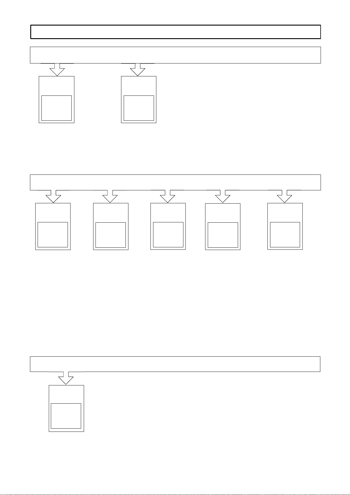
Short Commissioning, Standard Settings
The setting elements for the user–friendly interface are provided on the
parameter board, and for the standard interface on the control (refer to
Section 9 Attachment). For a standard commissioning procedure, the
tachometer adaptation, current normalization and current controller gain
parameters should be set.
Commissioning
stages of the FD
modules with the
user–friendly and
standard interface
Commissioning is sub–divided into various stages; after the standard settings
have been made, an additional commissioning stage can follow, or the unit can
be powered–up.
Short commissioning,
standard settings
Speed controller
optimization
Sec. 1
Sec. 2
1
VS
Supplementary
functions
Setpoint interfaces
Service and diagnostics
Attachment
Commissioning with
MSD option
Sec. 3
Sec. 4
Sec. 5
Powering–up, Sec. 7
Sec. 8
Sec. 9
Siemens AG 2000 All rights reserved
SIMODRIVE 611 analog Start–Up Guide (IAA) – 10.00 Edition
VS/1-3
Page 38

Feed Modules (VS)
1.2 Current controller settings
1.1 Tachometer adaptation for motors with tachometer
voltages ≤ 16.5 V at rated speed
Only involves motors 1FT503–AF71 and 1FT504–AF71
10.00
07.94
VS
User–friendly and
standard interface
All three contacts of switch S1 (S4 for a 2nd axis standard interface) = ON
In addition, discrete resistors can be used for calibration, refer to Sections
3.1 - 3.2.
1.2 Current controller settings
The settings for the current limit and current controller gain Kp(I) can be taken
from the adaptation tables, Table 1-3 up to Table1-9. The values can be determined according to the formulas if the required feed module/motor combination
cannot be found.
User–friendly
interface
Standard interface
Parameter board, switch S2
Control board, switch S2 (S5 for a 2nd axis)
Note
The following setting values apply for both control versions unless specific
differences are referred to in individual cases.
Actual value
normalization
Table 1-1 Current limit
S2.x
or
S5.x
to ON
(%) 100 85 68 61 50 46 41 39 36 34 30 29 26 25 24 23
– 2 3 234 2
Current limit =
The current limit must be at least reduced to the peak value permitted for the
particular motor. This may have to be further reduced depending on the
mechanical system.
I
(set maximum current)
max
I
(peak power module current)
limit
2
434
5 25352
3
4
4
2
3
5
5
3
4
4
5
5
[%] 100
2
3
4
5
VS/1-4
SIMODRIVE 611 analog Start–Up Guide (IAA) – 10.00 Edition
Siemens AG 2000 All rights reserved
Page 39

10.00
07.94
Current controller
gain Kp(I)
Table 1-2 Current controller gain
Kp(I) <
I
max
L
D
Feed Modules (VS)
1.2 Current controller settings
I
L
max
A
40
= selected max. current of the axis in A
= rotating field inductance of the motor in mH
(refer to the Planning Guide, AC Motors for Feed and Main Spindle
Drives)
S2.x
or
S5.x
to ON
Kp(I) 0.5 1 2 2.5 4 4.5 5.5 6 6.5 7.5 8 9.5 11 11.5
User–friendly
interface
– 6 7 6
The current controller gain setting range can be additionally increased using
R15 on the parameter board.
8 6
7
7
8
9 6
8
7
6
8
9
9
7
9
7
9
8
9
The following formula is valid for S2.6 to S2.9 closed (ON):
Kp(I) 11.5
1230
R15
Adaptation tables
Table 1-3 Adaptation table for 6SN112–1A00–0HA1 4/8 A power module
Servomotor Current limit
1FT... M
5034–AK71 0.5 0.93 6000 x o x o 3.68 o x o o 2.0
5036–AK71 0.75 1.4 6000 o x o o 5.44 o x o o 2.0
5042–AF71
5042–AK71
5044–AF71
5044–AK71
5046–AF71 2.6 3.0 3000 o o o o 8.0 o x o o 2.0
5062–AC71
5062–AF71
5062–AG71
5062–AK71
5064–AC71 4.5 2.7 2000 o o o o 8.0 o x o x 7.5
5066–AC71 6.5 3.9 2000 o o o o 8.0 x o x o 4.5
5070–AC71
5070–AF71
5070–AG71
5071–AC71 4.5 2.9 2000 o o o o 8.0 x x o x 8.0
[Nm] I
o
0.66
0.66
1.3
1.3
2.2
2.2
2.2
2.2
3.0
3.0
3.0
[A] n
o
0.75
1.2
1.5
2.3
1.3
2.0
2.7
3.9
1.8
2.6
3.6
rated
[RPM]
3000
6000
3000
6000
2000
3000
4000
6000
2000
3000
4000
Contacts
2 3 4 5
xxoxoox
ooxoooo
o
x
o
o
o
o
o
o
o
o
o
o
o
o
o
o
o
o
o
o
o
1)
I
[A]
max
2.72
o
4.88xxxxoooo
5.44
o
8.0
o
5.44
o
8.0
o
8.0
o
8.0
o
8.0
o
8.0
o
8.0
Current controller gain
Contacts
6 7 8 9
xxxooooo2.5
x
x
o
o
x
x
o
x
x
x
o
o
x
o
o
x
x
x
o
o
x
Kp(I)
x
x
o
o
x
x
o
6
7
8
9
2.5
2.5
1.0
11.5
7.5
4.0
1.0
11.5
7.5
4.5
VS
Definition: o = Contact in the basic OFF setting
x = Contact in the ON setting
1) The specified value is the maximum permissible current of the particular power module/motor combination. It may be
necessary to reduce the specified value depending on the driven mechanical systems.
Siemens AG 2000 All rights reserved
SIMODRIVE 611 analog Start–Up Guide (IAA) – 10.00 Edition
VS/1-5
Page 40

VS
Feed Modules (VS)
10.00
1.2 Current controller settings
Table 1-4 Adaptation table for 6SN112–1A00–0AA1 7.5/15 A power modules
Servomotor Current limit
1FT... M
5034–AK71 0.5 0.93 6000 o x x x 3.68 o x o o 2.0
5036–AK71 0.75 1.4 6000 o o o x 5.44 o x o o 2.0
5042–AF71
5042–AK71
5044–AF71
5044–AK71
5046–AF71
5046–AK71
5062–AC71
5062–AF71
5062–AG71
5062–AK71
5064–AC71
5064–AF71
5064–AG71
5066–AC71
5066–AF71
5070–AC71
5070–AF71
5070–AG71
5070–AK71
5071–AC71
5071–AF71
5071–AG71
5072–AC71 10.0 6.1 2000 o o o o 15.0 x x o x 8.0
5073–AC71
5073–AF71
5100–AC71 10.0 6.2 2000 o o o o 15.0 o x x o 5.5
[Nm] I
o
0.66
0.66
1.3
1.3
2.6
2.6
2.2
2.2
2.2
2.2
4.5
4.5
4.5
6.5
6.5
3.0
3.0
3.0
3.0
4.5
4.5
4.5
7.0
7.0
[A] n
o
0.75
1.2
1.5
2.3
3.0
4.7
1.3
2.0
2.7
3.9
2.7
4.1
5.5
3.9
6.0
1.8
2.6
3.6
5.3
2.9
4.3
5.2
4.3
6.4
rated
[RPM]
3000
6000
3000
6000
3000
6000
2000
3000
4000
6000
2000
3000
4000
2000
3000
2000
3000
4000
6000
2000
3000
4000
2000
3000
Contacts
2 3 4 5
xxxxxox
xxxxxoo
xoooooo
x
o
o
o
o
o
o
o
ooooooo
o
o
o
o
x
o
o
ooooooo
o
o
x
x
o
o
o
x
o
o
o
o
o
o
x
x
o
o
o
o
o
o
o
o
o
o
o
1)
I
[A]
max
3.45
x
4.5
5.85
o
9.15oooxxooo
12.7
o
15.0oxooxooo
x
5.1
o
7.5
o
10.2
o
15.0
o
10.2
o
15.0
o
15.0
15.0
o
15.0ooooxxxo
o
7.5
o
10.2
o
15.0
o
15.0
o
12.7
o
15.0
o
15.0
15.0
o
15.0ooooxxxo
Current controller gain
Contacts
6 7 8 9
oooxxooo4.0
o
x
x
x
o
o
x
x
x
o
o
x
o
x
x
x
x
o
o
x
x
o
o
x
x
x
o
x
o
x
o
x
x
o
o
o
x
x
o
x
o
o
x
x
x
x
o
x
x
o
x
x
o
x
x
o
07.94
Kp(I)
2.0
4.0
2.0
4.0
1.0
11.0
6.5
5.5
2.5
9.5
6.5
2.5
9.5
4.0
11.5
9.5
8.0
4.0
11.5
6.5
4.5
9.5
4.0
Definition: o = Contact in the basic OFF setting
x = Contact in the ON setting
1) The specified value is the maximum permissible current of the particular power module/motor combination. It may be
necessary to reduce the specified value depending on the driven mechanical systems.
VS/1-6
SIMODRIVE 611 analog Start–Up Guide (IAA) – 10.00 Edition
Siemens AG 2000 All rights reserved
Page 41

10.00
07.94
Feed Modules (VS)
1.2 Current controller settings
Table 1-5 Adaptation table for 6SN112–1A00–0BA1 12.5/25 A power modules
Servomotor Current limit
1FT... M
5036–AK71 0.75 1.4 6000 x x x x 5.75 o x o o 2.0
5044–AF71
5044–AK71
5046–AF71
5046–AK71
5062–AC71
5062–AF71
5062–AG71
5062–AK71
5064–AC71
5064–AF71
5064–AG71
5064–AK71
5066–AC71
5066–AF71
5066–AG71
5066–AK71
5070–AC71
5070–AF71
5070–AG71
5070–AK71
5071–AC71
5071–AF71
5071–AG71
5071–AK71
5072–AC71
5072–AF71
5072–AG71
5073–AC71
5073–AF71
5073–AG71
5073–AK71
5074–AC71 14.0 8.5 2000 o o o o 25.0 x x o x 8.0
5076–AC71 18.0 11.5 2000 o o o o 25.0 o x x o 5.5
5100–AC71
5100–AF71
5100–AG71
5101–AC71 15.0 9.4 2000 o o o o 25.0 o x x o 5.5
5102–AA71 27.0 9.9 1200 o o o o 25.0 x x o x 8.0
5103–AC71 19.0 12.0 2000 o o o o 25.0 o o x o 4.0
[Nm] I
o
1.3
1.3
2.6
2.6
2.2
2.2
2.2
2.2
4.5
4.5
4.5
4.5
6.5
6.5
6.5
6.5
3.0
3.0
3.0
3.0
4.5
4.5
4.5
4.5
10.0
10.0
10.0
7.0
7.0
7.0
7.0
10.0
10.0
10.0
[A] n
o
1.5
2.3
3.0
4.7
1.3
2.0
2.7
3.9
2.7
4.1
5.5
8.0
3.9
6.0
7.9
11.6
1.8
2.6
3.6
5.3
2.9
4.3
5.2
7.9
6.1
9.1
12.0
4.3
6.4
8.1
12.5
6.2
9.2
12.5
rated
[RPM]
3000
6000
3000
6000
2000
3000
4000
6000
2000
3000
4000
6000
2000
3000
4000
6000
2000
3000
4000
6000
2000
3000
4000
6000
2000
3000
4000
2000
3000
4000
6000
2000
3000
4000
Contacts
2 3 4 5
ooxoxox
oooxxoo
x
x
x
x
x
x
o
o
o
o
o
o
o
o
x
o
o
o
o
o
o
o
o
o
o
o
o
o
o
o
o
x
o
o
o
x
x
o
o
x
x
o
o
o
o
o
x
o
o
o
o
o
o
o
x
o
o
x
x
o
o
o
o
x
x
o
o
o
o
o
o
o
o
o
o
o
x
o
o
o
o
o
o
o
o
o
o
o
o
o
1)
I
[A]
max
6.0
x
9.0
12.5
o
17.0oooxxooo
x
5.75
x
8.5
o
10.25
o
15.75
o
10.25
o
17.0
o
25.0
o
25.0
o
17.0
o
25.0
o
25.0
o
25.0
x
7.5
o
11.5
o
17.0
o
25.0
o
12.5
o
17.0
o
25.0
o
25.0
o
25.0
o
25.0
o
25.0
o
17.0
o
25.0
o
25.0
o
25.0
o
25.0
o
25.0
o
25.0
Current controller gain
Contacts
6 7 8 9
oooxxooo4.0
x
x
x
o
x
x
x
o
x
o
x
x
o
x
o
o
x
x
x
x
x
x
o
x
o
x
x
x
o
o
x
x
x
o
x
x
x
o
x
x
o
o
x
x
x
o
o
x
o
o
x
o
x
o
x
x
x
x
o
x
o
o
x
x
x
o
x
o
x
o
x
x
o
o
x
o
o
x
o
o
o
x
o
o
o
x
o
x
x
o
Kp(I)
x
x
o
o
x
x
o
o
x
x
o
o
x
x
x
x
x
x
x
o
x
x
o
x
x
o
o
x
o
o
2.0
4.0
2.0
11.5
8.0
5.5
2.5
11.5
6.5
5.5
2.5
9.5
6.5
2.5
2.0
11.5
11.0
9.5
6.5
11.5
8.0
8.0
2.5
11.5
6.0
2.5
9.5
6.5
4.5
1.0
9.5
4.0
2.5
VS
Definition: o = Contact in the basic OFF setting
x = Contact in the ON setting
1) The specified value is the maximum permissible current of the particular power module/motor combination. It may be
necessary to reduce the specified value depending on the driven mechanical systems.
Siemens AG 2000 All rights reserved
SIMODRIVE 611 analog Start–Up Guide (IAA) – 10.00 Edition
VS/1-7
Page 42

VS
Feed Modules (VS)
10.00
1.2 Current controller settings
Table 1-6 Adaptation table for 6SN112–1A00–0CA1 25/50 A power modules
Servomotor Current limit
1FT... M
5044–AK71 1.3 2.3 6000 o o x x 13.0 x x o o 2.5
5046–AF71
5046–AK71
5062–AG71
5062–AK71
5064–AC71
5064–AF71
5064–AG71
5064–AK71
5066–AC71
5066–AF71
5066–AG71
5066–AK71
5070–AF71
5070–AG71
5070–AK71
5071–AC71
5071–AF71
5071–AG71
5071–AK71
5072–AC71
5072–AF71
5072–AG71
5072–AK71
5073–AC71
5073–AF71
5073–AG71
5073–AK71
5074–AC71
5074–AF71
5074–AG71
5074–AK71
5076–AC71
5076–AF71
5076–AG71
5100–AC71
5100–AF71
5100–AG71
5100–AK71
5101–AC71
5101–AF71
5101–AG71
5102–AA71
5102–AC71
5102–AF71
[Nm] I
o
2.6
2.6
2.2
2.2
4.5
4.5
4.5
4.5
6.5
6.5
6.5
6.5
3.0
3.0
3.0
4.5
4.5
4.5
4.5
10.0
10.0
10.0
10.0
7.0
7.0
7.0
7.0
14.0
14.0
14.0
14.0
18.0
18.0
18.0
10.0
10.0
10.0
10.0
15.0
15.0
15.0
27.0
27.0
27.0
[A] n
o
3.0
4.7
2.7
3.9
2.7
4.1
5.5
8.0
3.9
6.0
7.9
11.6
2.6
3.6
5.3
2.9
4.3
5.2
7.9
6.1
9.1
12.0
17.5
4.3
6.4
8.1
12.5
8.5
13.0
16.5
25.0
11.5
16.5
21.5
6.2
9.2
12.5
18.0
9.4
14.5
17.5
9.9
16.5
25.0
rated
[RPM]
3000
6000
4000
6000
2000
3000
4000
6000
2000
3000
4000
6000
3000
4000
6000
2000
3000
4000
6000
2000
3000
4000
6000
2000
3000
4000
6000
2000
3000
4000
6000
2000
3000
4000
2000
3000
4000
6000
2000
3000
4000
1200
2000
3000
Contacts
2 3 4 5
ooxooxx
xooxxxx
o
o
x
o
o
x
x
o
o
o
x
o
o
o
o
o
o
x
o
o
o
x
x
o
x
o
o
o
o
o
o
x
x
o
o
x
o
o
x
o
o
x
x
x
o
x
x
o
x
x
x
o
x
o
o
o
x
x
o
o
o
x
o
x
x
x
o
x
x
o
o
x
o
o
o
o
o
o
x
x
x
o
o
o
o
o
o
o
o
o
o
o
o
o
o
o
o
o
o
o
x
o
o
o
o
o
o
o
o
o
o
o
o
o
o
o
o
o
o
o
1)
I
[A]
max
15.0
o
25.0oxoxxooo
13.0
o
19.5xxoooxxo
x
13.0
o
19.5
o
25.0
o
34.0
o
19.5
o
30.5
o
34.0
o
50.0
x
12.0
x
17.0
o
25.0
x
13.0
o
20.5
o
25.0
o
34.0
o
25.0
o
42.5
o
50.0
o
50.0
o
20.5
o
30.5
o
42.5
o
50.0
o
42.5
o
50.0
o
50.0
o
50.0
o
50.0
o
50.0
o
50.0
o
30.5
o
42.5
o
50.0
o
50.0
o
42.5
o
50.0
o
50.0
o
42.5
o
50.0
o
50.0
Current controller gain
Contacts
6 7 8 9
x
x
x
x
x
o
x
x
x
x
x
x
x
x
o
o
o
x
x
o
o
x
o
x
x
o
o
x
x
o
o
x
x
o
o
x
o
x
x
x
x
x
x
o
x
x
x
x
x
x
o
x
o
x
o
o
x
x
o
x
x
x
x
x
o
x
o
x
x
o
o
x
o
x
x
x
x
x
o
x
x
x
o
x
x
o
o
o
x
x
o
x
x
o
x
o
x
x
x
x
o
x
x
x
x
x
o
x
x
o
x
x
x
x
o
x
o
o
x
x
o
x
o
x
o
o
x
x
o
x
x
o
o
o
x
x
x
o
o
o
x
x
o
x
x
o
o
o
x
x
x
o
o
o
x
x
o
x
o
o
07.94
Kp(I)
4.0
2.5
6.5
4.5
11.5
8.0
5.5
2.5
11.5
8.0
4.5
4.0
11.5
9.5
6.5
11.5
9.5
8.0
4.0
11.5
9.5
6.5
2.5
11.5
8.0
7.5
2.5
11.5
6.5
4.5
1.0
11.0
4.5
2.5
11.5
6.5
4.5
2.5
9.5
4.5
2.5
11.5
6.5
2.5
Definition: o = Contact in the basic OFF setting
x = Contact in the ON setting
1) The specified value is the maximum permissible current of the particular power module/motor combination. It may be
necessary to reduce the specified value depending on the driven mechanical systems.
VS/1-8
SIMODRIVE 611 analog Start–Up Guide (IAA) – 10.00 Edition
Siemens AG 2000 All rights reserved
Page 43

10.00
07.94
Feed Modules (VS)
1.2 Current controller settings
Table 1-6 Adaptation table for 6SN112–1AA00–0CA1 25/50 A power modules, continued
Servomotor Current limit
1FT... M
5103–AC71
5103–AF71
5103–AG71
5104–AA71
5104–AC71
5106–AA71 45.0 17.0 1200 o o o o 50.0 x x o x 8.0
5108–AA71 55.0 20.5 1200 o o o o 50.0 x o o x 6.5
5132–AA71 60.0 22.5 1200 o o o o 50.0 o x o x 7.5
[Nm] I
o
19.0
19.0
19.0
37.0
37.0
[A] n
o
12.0
17.5
23.0
14.0
22.5
rated
[RPM]
2000
3000
4000
1200
2000
Contacts
2 3 4 5
o
o
o
o
ooooooo
o
o
o
o
o
Definition: o = Contact in the basic OFF setting
x = Contact in the ON setting
1)
I
[A]
max
o
50.0
o
50.0
o
50.0
50.0
o
50.0xoxoxxxo
Current controller gain
Contacts
6 7 8 9
x
x
x
o
o
x
o
x
o
Kp(I)
o
o
x
8.0
2.5
2.0
11.5
4.0
VS
1) The specified value is the maximum permissible current of the particular power module/motor combination. It may be
necessary to reduce the specified value depending on the driven mechanical systems.
Siemens AG 2000 All rights reserved
SIMODRIVE 611 analog Start–Up Guide (IAA) – 10.00 Edition
VS/1-9
Page 44

Feed Modules (VS)
1.2 Current controller settings
Table 1-7 Adaptation table for 6SN112–1AA00–0DA1 40/80 A power modules
Servomotor Current limit
1FT M
4101–SK71
4101–SN71
4102–SG71 33.0 35.0 4000 o o o o 80.0 o o x o 4.0
5046–AK71 2.6 4.7 6000 o x o x 24.0 x x o o 2.5
5062–AK71 2.2 3.9 6000 o x x x 19.2 o o x o 4.0
5064–AF71
5064–AG71
5064–AK71
5066–AC71
5066–AF71
5066–AG71
5066–AK71
5070–AK71 3.0 5.3 6000 o x o x 24.0 x o o x 6.5
5071–AF71
5071–AG71
5071–AK71
5072–AC71
5072–AF71
5072–AG71
5072–AK71
5073–AC71
5073–AF71
5073–AG71
5073–AK71
5074–AC71
5074–AF71
5074–AG71
5074–AK71
5074–SG71
5074–SK71
5076–AC71
5076–AF71
5076–AG71
5076–AK71
5076–SG71
5100–AC71
5100–AF71
5100–AG71
5100–AK71
5101–AC71
5101–AF71
5101–AG71
5101–AK71
[Nm] I
o
20.0
20.0
4.5
4.5
4.5
6.5
6.5
6.5
6.5
4.5
4.5
4.5
10.0
10.0
10.0
10.0
7.0
7.0
7.0
7.0
14.0
14.0
14.0
14.0
16.0
16.0
18.0
18.0
18.0
18.0
20.5
10.0
10.0
10.0
10.0
15.0
15.0
15.0
15.0
[A] n
o
33.0
39.0
4.1
5.5
8.0
3.9
6.0
7.9
11.6
4.3
5.2
7.9
6.1
9.1
12.0
17.5
4.3
6.4
8.1
12.5
8.5
13.0
16.5
25.0
19.0
28.0
11.5
16.5
21.5
32.0
24.5
6.2
9.2
12.5
18.0
9.4
14.5
17.5
26.5
rated
[RPM]
6000
8000
3000
4000
6000
2000
3000
4000
6000
3000
4000
6000
2000
3000
4000
6000
2000
3000
4000
6000
2000
3000
4000
6000
4000
6000
2000
3000
4000
6000
4000
2000
3000
4000
6000
2000
3000
4000
6000
Contacts
2 3 4 5
ooooooo
o
x
o
o
o
o
o
o
o
x
o
o
o
o
o
o
x
o
o
o
o
o
o
o
o
x
x
o
o
o
x
o
o
o
o
o
o
o
x
o
o
o
x
x
x
o
o
o
x
x
o
o
x
o
o
o
x
o
o
o
x
x
o
o
o
o
x
x
x
o
x
x
o
o
x
x
o
o
o
o
o
o
o
o
o
x
o
o
o
o
o
o
o
o
o
x
x
o
x
x
o
o
o
o
x
x
o
o
o
o
o
1)
I
[A]
max
80.0
o
80.0oxxooooo
x
19.2
x
28.8
o
40.0
x
19.2
x
28.2
o
40.0
o
54.4
x
20.8
x
27.2
o
40.0
x
28.8
o
40.0
o
54.4
o
80.0
x
20.8
o
31.2
o
40.0
o
54.4
o
40.0
o
54.4
o
80.0
o
80.0
o
80.0
o
80.0
o
48.8
o
68.0
o
80.0
o
80.0
o
80.0
o
31.2
o
40.0
o
54.4
o
80.0
o
40.0
o
54.4
o
80.0
o
80.0
Current controller gain
Contacts
6 7 8 9
x
x
o
x
o
o
o
x
x
x
x
o
o
x
o
o
o
x
x
x
o
x
x
o
o
o
x
o
x
x
x
x
x
x
o
x
x
x
x
o
x
x
o
x
x
o
o
x
x
o
x
x
o
x
o
o
x
o
o
x
x
x
o
o
x
o
o
x
x
o
x
x
o
o
x
x
o
x
x
o
x
x
o
x
o
x
x
o
x
x
o
x
x
o
x
x
x
x
o
x
x
o
x
x
o
x
o
x
o
o
x
x
o
x
o
x
o
o
o
x
o
o
x
x
o
x
x
o
o
o
x
o
x
x
o
x
x
o
x
o
o
x
x
o
x
o
o
o
10.00
07.94
Kp(I)
2.0
1.0
8.0
6.5
4.0
11.5
8.0
6.0
4.5
9.5
8.0
4.5
11.5
9.5
7.5
5.5
11.5
8.0
6.5
2.5
11.5
7.5
6.5
2.5
6.0
2.5
11.0
6.5
4.5
2.0
4.0
11.5
6.5
5.5
4.0
8.0
5.5
4.5
2.0
Definition: o = Contact in the basic OFF setting
x = Contact in the ON setting
1) he specified value is the maximum permissible current of the particular power module/motor combination. It may be
necessary to reduce the specified value depending on the driven mechanical systems.
VS/1-10
SIMODRIVE 611 analog Start–Up Guide (IAA) – 10.00 Edition
Siemens AG 2000 All rights reserved
Page 45

10.00
07.94
Feed Modules (VS)
1.2 Current controller settings
Table 1-7 Adaptation table for 6SN112–1AA00–0DA1 40/80 A power modules, continued
Servomotor Current limit
1FT M
5102–AA71
5102–AC71
5102–AF71
5102–AG71
5103–AC71
5103–AF71
5103–AG71
5104–AA71
5104–AC71
5104–AF71
5106–AA71
5106–AC71
5108–AA71
5108–AC71
5132–AA71
5132–AC71
5132–SA71
5134–AA71
5134–SA71
5136–AA71 85.0 31.5 1200 o o o o 80.0 o x o x 7.5
5138–AA71 105.0 39.0 1200 o o o o 80.0 o o o x 6.0
[Nm] I
o
27.0
27.0
27.0
27.0
19.0
19.0
19.0
37.0
37.0
37.0
45.0
45.0
55.0
55.0
60.0
60.0
70.0
75.0
90.0
[A] n
o
9.9
16.5
25.0
31.5
12.0
17.5
23.0
14.0
22.5
34.0
17.0
26.8
20.5
32.5
22.5
35.5
26.0
28.0
34.0
rated
[RPM]
1200
2000
3000
4000
2000
3000
4000
1200
2000
3000
1200
2000
1200
2000
1200
2000
1200
1200
1200
Contacts
2 3 4 5
o
o
o
o
o
o
o
o
o
o
o
ooooooo
ooooooo
o
o
o
ooooooo
x
o
o
o
o
o
o
x
o
o
o
o
o
x
o
o
o
o
o
o
o
o
o
o
o
1)
I
[A]
max
o
40.0
o
80.0
o
80.0
o
80.0
o
54.4
o
80.0
o
80.0
o
54.4
o
80.0
o
80.0
80.0
o
80.0xoxxxxxo
80.0
o
80.0xxxoxxxo
o
80.0
o
80.0
o
80.0
80.0
o
80.0ooooxxxx
Current controller gain
Contacts
6 7 8 9
x
x
o
o
x
x
o
x
x
x
x
x
x
x
x
o
x
o
x
x
o
x
o
o
o
x
o
x
x
o
o
x
o
x
x
o
x
x
x
Kp(I)
x
x
o
o
x
x
o
x
x
o
x
o
x
11.5
9.5
4.0
2.5
8.0
6.0
2.5
11.5
6.5
2.5
11.5
5.5
11.5
4.5
11.5
4.5
11.5
9.5
9.5
VS
Definition: o = Contact in the basic OFF setting
x = Contact in the ON setting
1) he specified value is the maximum permissible current of the particular power module/motor combination. It may be
necessary to reduce the specified value depending on the driven mechanical systems.
Siemens AG 2000 All rights reserved
SIMODRIVE 611 analog Start–Up Guide (IAA) – 10.00 Edition
VS/1-11
Page 46

VS
Feed Modules (VS)
1.2 Current controller settings
Table 1-8 Adaptation table for 6SN112–1AA00–0EA1 80/160 A power modules
Servomotor Current limit
1FT M
4101–SK71
4101–SN71
4102–SG71
4102–SK71
4104–SG71
4104–SK71
4106–SG71 59.0 56.0 4000 o o o o 160.0 x o x o 4.5
5064–AK71 4.5 8.0 6000 o o x x 41.6 x o x o 4.5
5066–AG71
5066–AK71
5071–AK71 4.5 7.9 6000 o x x x 38.4 x o x o 4.5
5072–AF71
5072–AG71
5072–AK71
5073–AG71
5073–AK71
5074–AC71
5074–AF71
5074–AG71
5074–AK71
5074–SG71
5074–SK71
5076–AC71
5076–AF71
5076–AG71
5076–AK71
5076–SG71
5076–SK71
5100–AF71
5100–AG71
5100–AK71
5101–AC71
5101–AF71
5101–AG71
5101–AK71
5102–AA71
5102–AC71
5102–AF71
5102–AG71
5102–SF71
5102–SG71
5103–AC71
5103–AF71
5103–AG71
[Nm] I
o
20.0
20.0
33.0
33.0
45.0
45.0
6.5
6.5
10.0
10.0
10.0
7.0
7.0
14.0
14.0
14.0
14.0
16.0
16.0
18.0
18.0
18.0
18.0
20.5
20.5
10.0
10.0
10.0
15.0
15.0
15.0
15.0
27.0
27.0
27.0
27.0
34.0
34.0
19.0
19.0
19.0
[A] n
o
33.0
39.0
35.0
47.0
46.0
60.0
7.9
11.6
9.1
12.0
17.5
8.1
12.5
8.5
13.0
16.5
25.0
19.0
28.0
11.5
16.5
21.5
32.0
24.5
36.0
9.2
12.5
18.0
9.4
14.5
17.5
26.5
9.9
16.5
25.0
31.5
31.5
39.5
12.0
17.5
23.0
rated
[RPM]
6000
8000
4000
6000
4000
6000
4000
6000
3000
4000
6000
4000
6000
2000
3000
4000
6000
4000
6000
2000
3000
4000
6000
4000
6000
3000
4000
6000
2000
3000
4000
6000
1200
2000
3000
4000
3000
4000
2000
3000
4000
Contacts
2 3 4 5
oooooooo160.0
oooooooo160.0
oooooooo160.0
ooxoxox
o
o
o
o
oooxxxx
o
o
o
x
o
x
o
x
o
o
o
o
x
x
o
o
o
o
x
x
o
o
o
o
o
o
o
o
x
o
o
o
x
o
x
x
x
o
x
x
o
o
x
x
o
x
o
o
x
x
o
o
o
x
o
o
o
x
o
x
x
o
x
o
x
x
x
o
x
o
o
x
o
o
x
x
o
o
o
x
o
o
o
o
o
o
x
x
o
1)
I
[A]
max
160.0xxoxxooo
160.0xxxooxxo
160.0oxxxxooo
38.4
x
57.6oxoooxxo
x
41.6
x
57.6
o
80.0
41.6
o
65.5xooooxxo
x
41.6
o
65.6
o
80.0
o
97.6
o
80.0
o
97.0
x
48.0
o
73.6
o
108.8
o
160.0
o
108.8
o
160.0
x
46.4
o
62.4
o
80.0
x
41.6
o
65.6
o
80.0
o
136.0
x
46.4
o
80.0
o
108.8
o
160.0
o
108.8
o
160.0
x
57.6
o
80.0
o
108.8
6 7 8 9
o
x
o
x
x
x
x
o
x
o
o
x
o
o
o
x
x
o
o
x
x
o
x
o
o
o
x
x
x
o
x
Current controller gain
Contacts
o
x
x
x
x
x
o
x
x
x
o
x
o
o
x
o
x
o
o
o
o
o
o
x
o
x
x
o
o
x
o
o
x
o
x
x
o
x
x
o
x
o
x
o
o
x
o
o
o
x
x
o
x
o
x
x
o
x
o
x
o
o
x
o
x
x
o
x
x
o
x
x
o
x
o
x
x
x
x
x
o
x
o
x
o
x
o
o
x
o
x
x
o
10.00
07.94
Kp(I)
4.5
2.5
8.0
4.5
5.5
2.5
6.0
4.5
9.5
8.0
5.5
6.5
4.0
11.5
8.0
6.5
2.5
5.5
2.5
9.5
7.5
6.5
4.0
5.5
4.0
8.0
6.5
4.0
9.5
6.5
4.5
4.0
11.5
9.5
5.5
5.5
4.5
4.5
8.0
6.0
4.5
Definition: o = Contact in the basic OFF setting
x = Contact in the ON setting
1) he specified value is the maximum permissible current of the particular power module/motor combination. It may be
necessary to reduce the specified value depending on the driven mechanical systems.
VS/1-12
SIMODRIVE 611 analog Start–Up Guide (IAA) – 10.00 Edition
Siemens AG 2000 All rights reserved
Page 47

10.00
07.94
1.2 Current controller settings
Table 1-8 Adaptation table for 6SN112–1AA00–0EA1 80/160 A power modules, continued
1)
I
[A]
max
o
62.4
o
108.8
o
160.0
o
160.0
o
80.0
o
108.0
o
160.0
o
160.0
o
80.0
o
160.0
o
160.0
o
108.8
o
160.0
o
160.0
o
108.8
o
160.0
o
160.0
o
108.8
o
160.0
o
108.8
o
160.0
o
136.0
o
160.0
o
136.0
o
160.0
160.0xxxxxxxx
6 7 8 9
x
o
x
o
x
o
x
o
x
o
o
x
x
o
x
x
x
x
x
x
x
x
x
x
x
1FT M
5104–AA71
5104–AC71
5104–AF71
5104–SF71
5106–AA71
5106–AC71
5106–AF71
5106–SF71
5108–AA71
5108–AC71
5108–AF71
5132–AA71
5132–AC71
5132–AF71
5132–SA71
5132–SC71
5132–SF71
5134–AA71
5134–AC71
5134–SA71
5134–SC71
5136–AA71
5136–AC71
5136–SA71
5136–SC71
5138–AA71
5138–SA71
Servomotor Current limit
[Nm] I
o
37.0
37.0
37.0
48.0
45.0
45.0
45.0
57.0
55.0
55.0
55.0
60.0
60.0
60.0
70.0
70.0
70.0
75.0
75.0
90.0
90.0
85.0
85.0
110.0
110.0
105.0
140.0
[A] n
o
14.0
22.5
34.0
44.0
17.0
26.8
42.5
54.0
20.5
32.5
50.5
22.5
35.5
47.5
26.0
41.0
55.5
28.0
47.0
34.0
56.0
31.5
47.5
41.0
61.5
39.0
52.0
rated
[RPM]
1200
2000
3000
3000
1200
2000
3000
3000
1200
2000
3000
1200
2000
3000
1200
2000
3000
1200
2000
1200
2000
1200
2000
1200
2000
1200
1200
Contacts
2 3 4 5
x
x
o
o
o
o
o
o
o
o
o
o
o
o
o
o
o
o
o
o
o
o
x
o
x
o
oooooooo160.0
x
x
o
o
o
o
o
o
x
x
o
o
o
o
o
o
x
o
o
o
o
x
o
o
o
o
o
x
o
o
o
o
o
x
o
o
o
x
o
o
o
o
o
o
o
o
o
o
o
Feed Modules (VS)
Current controller gain
Contacts
x
x
o
x
o
o
x
x
x
x
x
o
o
x
o
x
x
x
o
x
o
x
x
x
x
o
x
x
x
x
x
o
x
x
x
x
o
o
x
x
o
o
x
x
o
o
x
x
o
o
Kp(I)
x
11.5
x
9.5
x
6.5
o
5.5
x
11.5
x
7.5
o
4.5
o
4.0
x
11.5
x
9.5
o
4.0
x
11.5
x
8.0
o
5.5
x
11.5
x
8.0
o
5.5
x
11.5
o
6.5
x
11.5
x
6.5
x
11.5
x
6.5
x
11.5
o
6.5
11.5
11.5
VS
Definition: o = Contact in the basic OFF setting
x = Contact in the ON setting
1) he specified value is the maximum permissible current of the particular power module/motor combination. It may be
necessary to reduce the specified value depending on the driven mechanical systems.
Siemens AG 2000 All rights reserved
SIMODRIVE 611 analog Start–Up Guide (IAA) – 10.00 Edition
VS/1-13
Page 48

VS
Feed Modules (VS)
1.2 Current controller settings
Table 1-9 Adaptation table for 6SN112–1AA00–0FA1 100/200 A power modules
Servomotor Current limit
1FT M
4101–SK71
4101–SN71
4102–SG71
4102–SK71
4104–SG71
4104–SK71
4106–SG71 59.0 56.0 4000 o o o o 200.0 o x x o 5.5
5066–AK71 6.5 11.6 6000 o x o x 60.0 x o x o 4.5
5072–AG71
5072–AK71
5073–AK71 7.0 12.5 6000 o x o x 60.0 o o x o 4.0
5074–AF71
5074–AG71
5074–AK71
5074–SG71
5074–SK71
5076–AC71
5076–AF71
5076–AG71
5076–AK71
5076–SG71
5076–SK71
5100–AF71
5100–AG71
5100–AK71
5101–AC71
5101–AF71
5101–AG71
5101–AK71
5102–AA71
5102–AC71
5102–AF71
5102–AG71
5102–SF71
5102–SG71
5103–AC71
5103–AF71
5103–AG71
5104–AA71
5104–AC71
5104–AF71
5104–SF71
5106–AA71
5106–AC71
5106–AF71
5106–SF71
[Nm] I
o
20.0
20.0
33.0
33.0
45.0
45.0
10.0
10.0
14.0
14.0
14.0
16.0
16.0
18.0
18.0
18.0
18.0
20.5
20.5
10.0
10.0
10.0
15.0
15.0
15.0
15.0
27.0
27.0
27.0
27.0
34.0
34.0
19.0
19.0
19.0
37.0
37.0
37.0
48.0
45.0
45.0
45.0
57.0
[A] n
o
33.0
39.0
35.0
47.0
46.0
60.0
12.0
17.5
13.0
16.5
25.0
19.0
28.0
11.5
16.5
21.5
32.0
24.5
36.0
9.2
12.5
18.0
9.4
14.5
17.5
26.5
9.9
16.5
25.0
31.5
31.5
39.5
12.0
17.5
23.0
14.0
22.5
34.0
44.0
17.0
26.8
42.5
54.0
rated
[RPM]
6000
8000
4000
6000
4000
6000
4000
6000
3000
4000
6000
4000
6000
2000
3000
4000
6000
4000
6000
3000
4000
6000
2000
3000
4000
6000
1200
2000
3000
4000
3000
4000
2000
3000
4000
1200
2000
3000
3000
1200
2000
3000
3000
Contacts
2 3 4 5
oxxooooo136.0
xooooooo170.0
oooooooo200.0
ooxxoxx
o
x
o
o
o
o
o
x
o
o
o
o
x
o
x
x
o
x
o
x
x
o
o
x
o
o
x
x
o
o
o
o
x
x
o
o
o
x
x
o
x
x
x
o
x
o
x
x
x
o
x
x
o
o
x
x
o
x
x
x
o
o
x
x
x
x
o
o
x
x
o
x
x
x
x
o
x
x
o
x
o
x
o
x
o
o
x
x
o
x
o
o
x
x
o
x
o
x
x
x
o
o
o
o
o
1)
I
[A]
max
170.0xxxxoooo
200.0oooxxxxo
200.0xxoxooxo
60.0
o
82.0xoxxoxxo
x
60.0
o
82.0
o
100.0
o
82.0
o
100.0
x
52.0
o
78.0
o
100.0
o
136.0
o
100.0
o
136.0
x
46.0
x
60.0
o
92.0
x
46.0
x
60.0
o
92.0
o
136.0
x
46.0
o
78.0
o
100.0
o
136.0
o
122.0
o
136.0
x
60.0
o
92.0
o
122.0
x
60.0
o
100.0
o
136.0
o
136.0
o
78.0
o
122.0
o
200.0
o
200.0
6 7 8 9
x
x
x
o
x
x
x
o
x
x
x
x
o
x
o
o
o
o
x
o
x
x
o
o
o
x
o
x
x
o
x
x
x
o
x
Current controller gain
Contacts
x
o
o
x
o
x
x
x
x
x
o
x
x
o
o
o
o
o
o
x
o
o
o
x
o
o
o
x
x
x
x
o
x
x
x
o
x
o
x
o
o
o
x
o
o
x
x
o
x
x
o
o
o
x
o
o
o
o
x
o
x
x
o
x
x
o
x
o
x
x
o
x
x
x
x
x
o
x
o
x
o
x
o
x
x
o
x
x
o
x
x
o
x
x
o
x
o
x
x
o
x
x
o
x
o
10.00
07.94
Kp(I)
2.5
2.0
9.5
5.5
6.5
2.5
8.0
5.5
8.0
6.5
2.5
6.0
2.5
11.5
8.0
5.5
2.5
4.5
2.5
8.0
6.0
4.5
9.5
6.0
6.0
4.0
11.5
9.5
4.5
4.5
5.5
4.0
9.5
6.5
5.5
11.5
8.0
5.5
4.5
11.5
8.0
5.5
4.5
Definition: o = Contact in the basic OFF setting
x = Contact in the ON setting
1) he specified value is the maximum permissible current of the particular power module/motor combination. It may be
necessary to reduce the specified value depending on the driven mechanical systems.
VS/1-14
SIMODRIVE 611 analog Start–Up Guide (IAA) – 10.00 Edition
Siemens AG 2000 All rights reserved
Page 49

10.00
07.94
1.2 Current controller settings
Table 1-9 Adaptation table for 6SN112–1AA00–0FA1 100/200 A power modules, continued
1)
I
[A]
max
o
92.0
o
136.0
o
200.0
o
100.0
o
170.0
o
200.0
o
100.0
o
170.0
o
200.0
o
122.0
o
200.0
o
122.0
o
200.0
o
136.0
o
200.0
o
136.0
o
200.0
170.0xxxxxxxx
6 7 8 9
x
x
x
x
o
x
x
o
x
x
x
x
x
x
x
x
x
Current controller gain
1FT M
5108–AA71
5108–AC71
5108–AF71
5132–AA71
5132–AC71
5132–AF71
5132–SA71
5132–SC71
5132–SF71
5134–AA71
5134–AC71
5134–SA71
5134–SC71
5136–AA71
5136–AC71
5136–SA71
5136–SC71
5138–AA71
5138–SA71
Servomotor Current limit
[Nm] I
o
55.0
55.0
55.0
60.0
60.0
60.0
70.0
70.0
70.0
75.0
75.0
90.0
90.0
85.0
85.0
110.0
110.0
105.0
140.0
[A] n
o
20.5
32.5
50.5
22.5
35.5
47.5
26.0
41.0
55.5
28.0
47.0
34.0
56.0
31.5
47.5
41.0
61.5
39.0
52.0
rated
[RPM]
1200
2000
3000
1200
2000
3000
1200
2000
3000
1200
2000
1200
2000
1200
2000
1200
2000
1200
1200
Contacts
2 3 4 5
x
o
o
o
o
x
o
o
x
o
x
o
x
o
o
o
o
o
xxoooooo170.0
x
x
o
o
o
o
x
o
o
o
o
o
x
o
o
o
o
x
o
o
o
x
o
o
o
x
o
o
o
x
o
o
o
Feed Modules (VS)
Contacts
x
x
x
o
o
x
x
x
o
x
o
o
x
x
o
x
o
o
x
x
x
o
x
x
x
o
x
x
x
o
x
x
x
o
Kp(I)
x
11.5
x
8.0
o
4.5
x
11.5
x
9.5
x
6.5
x
11.5
x
9.5
x
6.5
x
11.5
x
8.0
x
11.5
x
8.0
x
11.5
x
8.0
x
11.5
x
8.0
11.5
11.5
VS
Definition: o = Contact in the basic OFF setting
x = Contact in the ON setting
1) he specified value is the maximum permissible current of the particular power module/motor combination. It may be
necessary to reduce the specified value depending on the driven mechanical systems.
Siemens AG 2000 All rights reserved
SIMODRIVE 611 analog Start–Up Guide (IAA) – 10.00 Edition
VS/1-15
Page 50

VS
Feed Modules (VS)
1.2 Current controller settings
Space for notes
10.00
10.00
07.94
VS/1-16
SIMODRIVE 611 analog Start–Up Guide (IAA) – 10.00 Edition
Siemens AG 2000 All rights reserved
Page 51

07.94
Feed Modules (VS)
2 Speed Controller Optimization
Speed Controller Optimization
The additional smoothing functions in the controller loop (to dampen mechanical
resonance points) are described in Section 3. Proceed as follows when
optimizing the speed:
1. Tachometer calibration
2. Gain Kp
3. Integral action time T
4. Adaptation T
5. I component limiting (if necessary)
6. Drif compensation (offset)
The unit must be powered–up to optimize the speed controller, regarding
Sections 2.1, 2.2, 2.3 and 2.8. Therefore observe Section 7 “Powering–up”.
The potentiometer scaling is defined as follows (in the setting tables):
7
7
6
6
5
5
4
4
3
3
N
9
9/
8
10
8
0/1
2
2
1
N
The setting shown in the diagram
corresponds to 7 scale sections.
10
0
2
VS
(if necessary)
Siemens AG 2000 All rights reserved
SIMODRIVE 611 analog Start–Up Guide (IAA) – 10.00 Edition
VS/2-17
Page 52

Feed Modules (VS)
2.1 Tachometer calibration
2.1 Tachometer calibration
For motors with a tachometer voltage ≤ 16.5 V, proceed as described in
Section 1.1.
Potentiometer Setting range
T
0.7 n
rated
n
act N
2.2 n
10.00
07.94
rated
VS
/ n
2.2
act
2
1.8
1.6
1.4
1.2
1
0.8
0.6
0 1 2345678910
Tachometer potentiometer (scaling)
n
act N
Fig. 2-1 Tachometer calibration
Extended setting range using R3 and R10 (only for the user–friendly
interface).
Function Component Value
n
n
act N
act N
> 0.7 n
< 2.2 n
rated
rated
Increase R3 0 Ω (as supplied)
Insert R10 Open–circuit (as supplied)
VS/2-18
SIMODRIVE 611 analog Start–Up Guide (IAA) – 10.00 Edition
Siemens AG 2000 All rights reserved
Page 53

10.00
07.94
Feed Modules (VS)
2.2 Setting the proportional gain Kp without adaptation
2.2 Setting the proportional gain Kp without adaptation
The proportional gain Kp of the speed controller can be set using potentiometer
Kp. The range can be extended, if required using a fixed resistor R50 (only
user–friendly interface; R50 = 68 kΩ (when supplied)). The gain, set using the
Kp potentiometer is additionally influenced by the setting of the T
meter.
Kp
170
160
potentio-
N
Potentiometer T
N
VS
140
120
100
80
60
40
20
0
0 1 2345678910
Setting, potentiometer Kp
Fig. 2-2 Proportional gain Kp as a function of the Kp potentiometer and TN potent.
Right–
hand end
stop
Center
Left–hand
end stop
Siemens AG 2000 All rights reserved
SIMODRIVE 611 analog Start–Up Guide (IAA) – 10.00 Edition
VS/2-19
Page 54

VS
Feed Modules (VS)
2.3 Setting the integral action time TN without adaptation
2.3 Setting the integral action time TN without adaptation
Speed controller integral action time is set using potentiometer TN, the range
can be extended, when required, using C2 (only for the user–friendly interface).
TN in ms
45
40
30
20
10
0
0 1 2345678910
Setting, potentiometer T
10.00
07.94
N
Fig. 2-3 Integral action time TN as a function of potentiometer T
N
VS/2-20
SIMODRIVE 611 analog Start–Up Guide (IAA) – 10.00 Edition
Siemens AG 2000 All rights reserved
Page 55

10.00
07.94
Feed Modules (VS)
2.4 Integral action time with adaptation (if required)
2.4 Integral action time with adaptation (if required)
Resistor R34 (only for the user–friendly interface) or switch S3.5 (S6.5 for the
2nd axis) for the standard interface is used to activate and pre–set the adaptation.
R34 = open
R34 = inserted
T
N
R34 + pot. ADAPT
T
Nadapt
n
Adaptation
fully
effective
Fig. 2-4 Adaptation of the integral action time
x2
Adaptation inactive (as supplied)
Adaptation operates according to the following
diagrams
n
Transition
range
x1
Adaptation
ineffective
Pot. T
VS
N
n
x
n
Fig. 2-5 Inter–dependency of adaptation T
= n
+ n
x
set
T
Nadapt/TN
0.9
0.7
0.5
0.3
0.1
0
act
0 1 2345678910
Potentiometer setting ADAPT
R34 = 10 k
R34 = 0
or standard
interface
N
Siemens AG 2000 All rights reserved
SIMODRIVE 611 analog Start–Up Guide (IAA) – 10.00 Edition
VS/2-21
Page 56

Feed Modules (VS)
2.5 P gain with adaptation (only user–friendly interface)
2.5 P gain with adaptation (only user–friendly interface)
Important
!
Offsets can occur in the transition range.
R38 is used to activate and pre–set adaptation (if required):
03.96
07.94
VS
R38 = open
R38 = inserted
Kp
Kp
adapt
R38
Kp
Adaptation
fully
effective
Fig. 2-6 Proportional gain Kp as a function of the speed
x
= n
Kp
35
set
adapt
+ n
/Kp
ist
n
Adaptation inactive (as supplied)
Adaptation operates according to the following
diagrams
R50 + pot. Kp
n
x2
Transition
range
n
x1
Adaptation
ineffective
n
x
VS/2-22
25
15
5
0
0 500 1000 1500 2000 2500
Fixed resistor R38 in
Fig. 2-7 Adaptation Kp as a function of R38 in the “adaptation fully effective” range
SIMODRIVE 611 analog Start–Up Guide (IAA) – 10.00 Edition
Siemens AG 2000 All rights reserved
Page 57

10.00
07.94
Feed Modules (VS)
2.8 Drift compensation (offset)
2.6 Setting the adaptation range (generally not required)
The adaptation range can be set via the following resistors:
R40 User–friendly interface
R543 Standard interface 1st axis (Order No.[MLFB[ 6SN1118–0AD11–0AA1)
R544 Standard interface 2nd axis (Order No.[MLFB] 6SN1118–0AE11–0AA1)
R = open
R = inserted
R40 in k
150
130
Adap-
110
tation
fully
90
effective
70
50
30
10
0
0 50 100 150 200 250 300 350 400
Fig. 2-8 Adaptation range
x
= n
set
+ n
act
n
Max. adaptation range (as supplied)
Adaptation, reduced acc. to the following diagram
Transition range
Adaptation ineffective
VS
nx in mV
2.7 I–component speed controller limiting
R52 User–friendly interface
R547 Standard interface, 1st axis (from Order No. 6SN1118–0AD11–0AA1)
R550 Standard interface, 2nd axis (from Order No. 6SN1118–0AE11–0AA1)
R = open–circuit
R = 0 Ω
I–component fully effective (as supplied)
I–component, not effective
As limit for the speed controller I component, between 100 kΩ and 2 MΩ can be
set for R52, e.g. for slip–stick effects.
2.8 Drift compensation (offset)
This is calibrated using a potentiometer for n
short–circuited)
Potentiometer drift Control range 30 mV
set
= 0 (terminal 56 and terminal14
Siemens AG 2000 All rights reserved
SIMODRIVE 611 analog Start–Up Guide (IAA) – 10.00 Edition
VS/2-23
Page 58

VS
Feed Modules (VS)
2.8 Drift compensation (offset)
Space for notes
10.00
07.94
VS/2-24
SIMODRIVE 611 analog Start–Up Guide (IAA) – 10.00 Edition
Siemens AG 2000 All rights reserved
Page 59

12.9404.97
07.94
Feed Modules (VS)
3.1 Setting elements with the standard interface
Supplementary Commissioning Functions
3.1 Setting elements with the standard interface
Setting elements, switches S2 and S3 or S5 and S6 for the 2nd axis
Contacts, S2/S5
10 x DIL
1 Motor, clockwise direction of
2...5 Current normalization
6...9 Current controller gain (0.5)
10 Closed–loop speed controlled
Contacts S3/S6
8 x DIL
1 Speed setpt. smoothing W/out smoothing1)with T= 2.2 ms
2 Speed actual value
3 Speed contr. smoothing W/out smoothing1)with T= 370 µs
4 Current setpt. smoothing W/out smoothing1)with T= 110 µs
5 Speed contr. adaptation OFF
6 Ready/fault
7 Master/slave
8 Current–contr. operation With I component W/out I
rotation for a positive speed setpoint (motor shaft drive end) at
terminal 56/14
(I
=100 %)
max
operation
smoothing
OFF ON
Motor, counter–clockwise di-
rection rotation for a positive
speed setpoint (motor shaft drive
end) at terminal 56/14
1)
1)
Function OFF ON
2)
3)4)
Current normalization
(I
=23 %)
max
1)
Current controller gain (11.5)
Closed–loop current controlled
operation
W/out smoothing1)with T= 280 µs
1)
Ready signal
1)
Master
1)
ON T
Fault signal
Slave
component
3
VS
4)
1)
1) Status as supplied
2) Important!
This acts on the BB relay of the NE/monitoring module. If the user–friendly and standard interface are operated
together, or the standard interface alone, then if the enable is not present or there is a fault of the standard axes, the
BB relay of the NE module drops–out.
3) Function only for a 2–axis version
4) Slave axis must be operated in the closed–loop current controlled mode with enabled I component.
Siemens AG 2000 All rights reserved
SIMODRIVE 611 analog Start–Up Guide (IAA) – 10.00 Edition
VS/3-25
Page 60

VS
Feed Modules (VS)
04.97
07.94
3.1 Setting elements with the standard interface
The following supplementary functions can be set by mounting wired components on the basic board (from Order No.[MLFB] 6SN11 18–0AD11–0AA1 (1
axis) or from Order No.[MLFB] 6SN11 18–0AE11–0AA1 (2 axes).
Function BKZ axis1 BKZ axis 2 Value range
Smoothing, speed controller C231 C235 0 ... 100nF
Smoothing, n
Smoothing, n
Smoothing I
Timer stage ”speed controller at its end-
stop”
Tachometer adaptation R539, R540, R541 R536, R537. R538 0 ... k, 0.1%, 25ppm/K
Clock cycle frequency, PB M R542 R542 62 k ...
Adaptation range R543 R544 0 ... k
Speed setpoint adaptation R545 R546 0 ... k
Limit, speed controller I–component R547 R550 100 k ... 2 M
Electr. weight equalization pos./neg. R548/R549 R551/R552 20 k ...
Response threshold I2t monitoring
set
act
set
C232 C236 0 ... 2.2 F
C233 C237 0 ... 100nF
C234 C238 0 ... 100nF
C239 C240 0 ... 2.2 F
R553 R554 0 ... k
Note
Important
Axial metal film resistors, packaging type 0204 (RM 7.62 mm) or radial MKT
capacitors (RM 5.08 mm) should be mounted at the mounting locations provided. When adapting the tachometer, it should be noted that the (3) resistors
have a relative accuracy of 0.1% with respect to one another and a Tk of
< 25 ppm/K.
The board can be damaged if incorrect materials are used.
Only trained personnel may carry–out any soldering work on the board (maintai-
ning the ESD Guidelines).
VS/3-26
SIMODRIVE 611 analog Start–Up Guide (IAA) – 10.00 Edition
Siemens AG 2000 All rights reserved
Page 61

04.97
07.94
Feed Modules (VS)
3.1 Setting elements with the standard interface
3.1.1 Dimensioning the setting elements (Standard interface)
a) Smoothing functions
Speed controller: T=C231(C235) 78 k
n
: T=C232(C236) 10 k
set
: T=C233(C236) 10 k (dep. on the tacho. pot. setting)
n
act
I
: T=C234(C238) 5 k
set
b) Timer, ”speed controller at its endstop”
The monitoring time is, as standard 230 ms, and when required can be increased by mounting C239 (C240). In this case, the following relationship exists:
T
=
Zst
c) Tachometer adaptation
The following equivalent circuit diagram is valid for the individual tachometer
voltages:
V
Tach
4 k
d) Clock cycle frequency PBM
If noise problems develop (a motor which whistles), the clock cycle frequency of
the PWM inverter can be adapted for both axes together (Fig. 3–1).
However, it must be taken into account that the available current ( In, I
is reduced when the clock cycle freq. is increased (ref. to PJU Section 4.1).
2
The I
max. ambient temperature of 40C. If these values are exceeded (pulse frequency and/or ambient temperature), the response threshold must be adapted
(refer to Fig. 3-2).
C239 (C240)
1.15 +
(
R
20 k
t limiting is designed for a factory–set pulse frequency of 3.3 kHz and a
F
x
V
Tach X
8 k
200 ms
)
The tachometer voltage V
rated speed, which provides a voltage V
V. Different values can be used corresponding to
this criteria for a rated motor speed which deviates
significantly from the useful speed. The following
formula applies:
V
5k
Rx=
1–
Tach
(
V
TachX
V
1
Tach
4
(
V
TachX
is generally 40 V at
Tach
–7.5 k
)
][
)
TachX
of 10
max
VS
)
8.0
7.5
7.0
6.5
6.0
5.5
5.0
4.5
Frequency [kHz]
4.0
3.5
3.0
2.5
0
10 100 1000
Frequency
Typ. value, series
Fig. 3-1 Clock–cycle frequency of the PWM inverter
R542 [k]
10000
Siemens AG 2000 All rights reserved
SIMODRIVE 611 analog Start–Up Guide (IAA) – 10.00 Edition
VS/3-27
Page 62

Feed Modules (VS)
3.1 Setting elements with the standard interface
e) Speed setpoint adaptation
If the adjustment range of the tachometer potentiometer (for low speed ranges)
is not sufficient, then the speed setpoint can be adapted using the setpoint voltage divider. The following circuit diagram applies:
04.9704.97
07.94
VS
N
set
20 k 20 k
R
x
N controller
virt. M
The following relationship is obtained for R545 (R546):
n
required
Rx=10k
n
– n
rated
required
f) Limiting, I component, speed controller (refer to 2.7)
The maximum I component of the speed controller can be limited by inserting
R547 (R550).
g) Electronic weight equalization
The value to be set for the electronic weight equalization is obtained from the
current setpoint I
enbled at standstill (N
10V
R=
I
setGwa
10k
which can be measured at test socket T with the axis
setGwa,
=0):
set
Caution: I
5V R 20 k!
setGwa
After the resistor has been inserted, the value, with the axis inhibited, must be
able to be measured at test socket T with the same sign (polarity).
2
h) Response threshold I
t monitoring
The I2t monitoring limits the current setpoint to the thermally permissible value.
The response threshold is 55% of the peak power module current, and can be
reduced, corresponding to the following characteristic by inserting R553 (R554):
Response threshold I2t monitoring
60
50
40
30
20
Response threshold [% I_limit]
10
0
1 10 100
Fig. 3-2 Response threshold I2t monitoring
R553 (R554) [k]
1000
VS/3-28
SIMODRIVE 611 analog Start–Up Guide (IAA) – 10.00 Edition
Siemens AG 2000 All rights reserved
Page 63

04.97
07.94
3.2 Setting elements with user–friendly interface
3.2 Setting elements with user–friendly interface
Setting elements on the parameter board;
Terminal = H → connected to terminal 9, terminal = L →open–circuit.
Function Component(s) Effect
Ready/fault
relay terminal 672/673/674
Speed/current control (permanently set
via switch)
Speed/current controlled (selected via
terminal)
Supplementary setpoint 1
via terminal 22 = H
Supplementary setpoint 2
via terminal 23 = H
Current–controlled operation with/without I component
Controller and pulse inhibit via term. 65 R13 = open (as supplied)
Master-/slave oper.: master operation
slave operation R44 = 0 Ω, R1 + R42 = open,
Timer, speed controller at its endstop
Monitoring, speed controller at its endstop
Direction of rotation reversal
(direction of rotation for a positive
setpoint at terminal 56/14)
Speed controller smoothing C3 (as supplied = open) τ = C3 68 kΩ
Speed setpoint smoothing C4 (as supplied = open) τ = C4 10 kΩ
Speed actual value smoothing C5 (as supplied = open) τ = C5 5 kΩ
Current setpoint smoothing C6 (as supplied = open) τ = C6 1 kΩ
Speed setpoint adaptation
(only terminal 56/14)
Current setpoint adaptation R42 (as supplied = 0 Ω)
Travel to fixed endstop (fixed setting via
R12)
2)
R33 = 0 Ω (as supplied)
R33 = open
S2: 10 = OFF (as supplied)
S2: 10 = ON
R14 = 0 Ω1); Term.22 = L
R14 = 0 Ω; Term.22 = H
R17 (as supplied = open)
R16 (as supplied = open)
R18 (as supplied = open)
R21 (as supplied = open)
R19 (as supplied = open)
R22 (as supplied = open)
R1 = 0 Ω (as supplied)
R1 = open
R13 = 0 Ω
R42 + R44 = 0 Ω, S2: 10 = OFF Master operation, term. 258 = output
S2: 10 = ON
R54 = 360 kΩ (as supplied)
R54, as selected
R32 = 0 Ω (as supplied)
R32 = open
S2: 1 = ON (as supplied)
S2: 1 = OFF
R5 = 20 kΩ (as supplied)
R12 acc. to Fig. 3–3
Condition: term. 96 connected to
terminal 44
2)
2)
2)
Ready signal
Fault signal
Speed–controlled
Current–controlled
Speed–controlled
Current–controlled
Voltage divider at 10 V
Voltage divider at –10 V
Voltage divider at the reference point
Voltage divider at 10 V
Voltage divider at –10 V
Voltage divider at the reference point
I component inhibited P
I component active PI
Delayed
Instantaneous
Slave operation, term. 258 = input
t = 230 ms
R54 [kΩ] =
Monitoring active
Monitoring inactive
Motor counter–clockwise rotation,
motor drive shaft end
Motor clockwise direction of rotation,
motor drive shaft end
|100% n
I
10 V
set
Limiting according to Fig. 3–3
speed controller monitoring inactive
t [ms]
0.56
ACT N
Feed Modules (VS)
VS
– 47
|=11 ... 5V
1) As supplied: R14 = open
N
2) R=
Siemens AG 2000 All rights reserved
SIMODRIVE 611 analog Start–Up Guide (IAA) – 10.00 Edition
set
10 V
N
rated
()
N
max
– 0.5
40k
VS/3-29
Page 64

VS
Feed Modules (VS)
3.2 Setting elements with user–friendly interface
Function Component(s) Effect
Travel to fixed endstop (variable
via term. 96)
Setting–up operation (central
via term. 112 on the NE module)
Current reduction after the timer, speed controller at endstop, has expired
Current reduction after the I2t
timer has expired
Response threshold I2t R9 = 30 kΩ (as supplied)
Electronic weight equalization R46 + R48 = open (as supplied)
Tachometer adaptation
Clock cycle frequency R542 Refer to Fig. 3-1
1)
R12 = open (as supplied)
Volt. at term. 96 acc. to Fig. 3-4
R12 acc. to Fig. 3-3
KL112 = open
(as supplied term. 112 connected to terminal 9)
R2 acc. to Fig. 3-5
R32 = open
R2 = open (as supplied)
R32 = open
R9 acc. to Fig. 3-6
R46 for neg. I–set at socket T
R48 for pos. I–set at socket T
R6, R7, R8 tolerance 0.1%
Limiting acc. to Fig. 3-4,
Speed controller monitoring inactive
Limiting acc. to Fig. 3-3,
Speed controller monitoring inactive
Reduction, acc. to Fig. 3-5
speed controller monitoring disabled
S1 duty = 1.1 I
S1 duty = 1.1 I
Limiting, acc. to 3-6
No weight equalization
Supplementary I set according to Fig. 3-7
Supplementary I set according to Fig. 3-7
5 k
[
Rx=
1–
1
rated
rated
(
4
V
Tach
04.97
07.94
]
–7.5 k
TachX
V
TachX
)
)
U
V
Tach
(
I
[%]
set
I
max
100
90
80
70
60
50
40
30
20
10
0
0.1 1.0 10.0 100.0 1000.0
R12 [k]
Fig. 3-3 Current setpoint limiting as a function of R12, 30 V terminal 96 12 V
Limit
value
1%
1) refer to VS/Section 3.1.1
VS/3-30
SIMODRIVE 611 analog Start–Up Guide (IAA) – 10.00 Edition
Siemens AG 2000 All rights reserved
Page 65

04.97
07.94
100
90
80
70
60
50
I
I
set
max
Feed Modules (VS)
3.2 Setting elements with user–friendly interface
[%]
40
30
20
10
0
1 3
0
Fig. 3-4 Current setpoint limiting as a function of the voltage at 96 (R12 = open)
I
set
I
max
100
90
80
70
60
50
40
30
20
10
Initial
0
value
1.0
1%
2
[%]
4
6 875 9 10
10.0 100.0
Final
value
1%
V
term.96
R2 [kΩ]
VS
[V]
Fig. 3-5 Current setpoint limiting as a function of R2
Siemens AG 2000 All rights reserved
SIMODRIVE 611 analog Start–Up Guide (IAA) – 10.00 Edition
VS/3-31
Page 66

VS
Feed Modules (VS)
3.2 Setting elements with user–friendly interface
I
cont.
[%]
I
rated
110
100
90
80
70
60
50
40
30
20
10
0
10.0 100.0
Inadmissible range
04.97
07.94
1000.0
R9 [kΩ]
Fig. 3-6 Response threshold, I2t monitoring as a function of R9
I
Weightequal./Imax
1.0
0.8
0.6
0.4
0.3
0.2
0.1
0.08
0.06
0.04
0.03
0.02
0.01
5
6.8 10 15 22 27 394756
5.6
Fig. 3-7 Supplementary current setpoint for electronic weight equalization
Inadmissible range
68
150 220 390
100
470
R46 or
R48 [k]
680 1000
Inverter clock cycle frequency PBM
When noise problems develop (the motor makes a whistling sound), the clock
cycle frequency of the PWM inverter can be changed by inserting R369 on the
basic board.
However, it should be noted, that the available current (I
, I
n
max
) is reduced
when the clock cycle frequency is increased (refer to PJU Section 4.1)
The I2t limiting is designed for a factory–set pulse frequency of 3.3 kHz and a
max. ambient temperature of 40 C. If this value is exceeded (pulse frequency
and/or ambient temperature), the response threshold must be changed (refer to
Fig. 3-2). The characteristic according to Fig. 3-1 applies.
VS/3-32
SIMODRIVE 611 analog Start–Up Guide (IAA) – 10.00 Edition
Siemens AG 2000 All rights reserved
Page 67

12.94
07.94
Feed Modules (VS)
4 Setpoint Interfaces
Setpoint Interfaces
Definitions:
Optimum, taking into account the properties of the setpoint input
X
Possible
Not permitted, also in some cases not possible
Table 4-1 Main setpoint – supplementary setpoints
Operating mode Setpoint Terminal
Speed controlled
Current controlled
Slave I controlled Main setpoint X
current setpoint input
MSD option Main setpoint X
MSD operation
MSD option Main setpoint X
C axis
Main setpoint X
Suppl. setpoint X X X X
Main setpoint X
Suppl. setpoint X
Suppl. setpoint
Suppl. setpoint
Suppl. setpoint X X
56/14
Terminal
24/20
Int.
setpoint
term. 22
Int.
setpoint
term. 23
SocketNZTerminal
4
VS
258
Table 4-2 Motor direction of rotation for a positive setpoint and S2.1 = ON
Mode Term. 56/14 Term. 24/20 T erm. 22 Term. 23 Socket NZ Master/slave
Speed–controlled Left Right
Current–controlled Right
When viewing the motor shaft drive end
Siemens AG 2000 All rights reserved
SIMODRIVE 611 analog Start–Up Guide (IAA) – 10.00 Edition
R16/18 right R19/22 right
R17/18 left R21/22 left
R16/18 right R19/22 right
R17/18 left R21/22 left
Left
Term. 258
Right
Right
(slave)
VS/4-33
Page 68

VS
Feed Modules (VS)
4 Setpoint Interfaces
Space for notes
10.00
07.94
VS/4-34
SIMODRIVE 611 analog Start–Up Guide (IAA) – 10.00 Edition
Siemens AG 2000 All rights reserved
Page 69

04.97
07.94
Feed Modules (VS)
5.1 Pre–settings
Commissioning with the MSD Option
Control parameter settings for C–axis operation on the parameter board, control
parameters for MSD operation on the option board.
The components which can be modified for the MSD option are mounted on
solder pins (layout, refer to Section 9).
The scale divisions of the potentiometers (in the setting tables) are defined as
follows:
9/
10
9
8
5.1 Pre–settings
10
8
7
7
6
6
0
0/1
1
2
2
3
3
4
5
4
5
The setting shown in the diagram
corresponds to 7 scale units.
5
VS
Warning
!
Changes on the parameter board: Remove R4, R5 and R54, if required, C4
(not mounted when supplied).
Undesirable axis motion can occur if this information is not observed!
5.1.1 Settings with the control board withdrawn
Ramp–up time
Table 5-1 Ramp–up time from 0 V to 10 V in s via terminal 56/14, setting via potentiometer
Terminal 102 open 0.01 0.11 0.21 0.31 0.4 0.5 0.6 0.7 0.8 0.9 1.11
Terminal 102 at
terminal 9
The ramp–up time range via R20 can be changed by modifying R27/R60.
R20 and terminal 102
0 1 2 3 4 5 6 7 8 9 10
0.1 1.08 2.07 3.06 4.04 5.03 6.02 7.01 8.01 9.04 11.05
Siemens AG 2000 All rights reserved
SIMODRIVE 611 analog Start–Up Guide (IAA) – 10.00 Edition
VS/5-35
Page 70

Feed Modules (VS)
5.1 Pre–settings
Torque limiting
04.97
07.94
VS
I/I
max
R76
100
13
23 70 100
Fig. 5-1 Torque limiting
Table 5-2 Suitable start of the “constant power” range referred to
Potentiometer
R214
Start of the
range in %
Table 5-3 Deviations of the selected power to the constant power at the point
n
= 10 V in % via R214
max
0 1 2 3 4 5 6 7 8 9 10
70 65 60 55 50 45 40 35 30 26 22
n
in % via R213
max
“Constant power”
R214
range
R213
n/n
rated
R225
in %
Potentiometer
R213
Start of the
range in %
Table 5-4 Constant torque limiting I
R76 in kΩ 3 4.3 6.2 8.2 11 15 18 22 27 36
I
in % 10 20 30 40 50 60 70 80 90 100
set/Imax
0 1 2 3 4 5 6 7 8 9 10
+20 0 –20
in % via R76 (solder pins), R76 is open
when the equipment is supplied
set/Imax
Intermediate values are determined using interpolation
Table 5-5 Speed–dependent torque limiting I
R225 in kΩ 2.4 4.7 7.5 11 16 22 30 47 70 100
I
set/Imax
12% I
set/Imax
R226 = 20 kΩ
in % 1 10 20 30 40 50 60 70 80 85
is set as standard. Intermediate values are obtained using
in % via R225 (solder pins) for
set/Imax
interpolation.
VS/5-36
SIMODRIVE 611 analog Start–Up Guide (IAA) – 10.00 Edition
Siemens AG 2000 All rights reserved
Page 71

04.97
07.94
Normalization of
the M/P display
Feed Modules (VS)
5.1 Pre–settings
Table 5-6 Normalization via potentiometer R903 (as supplied, factor = 1)
Pot. R903 0 1 2 3 4 5 6 7 8 9 10
Normalization factor
3 2.8 2.6 2.4 2.2 2.0 1.8 1.6 1.4 1.2 1
Relay function,
output of two limit
value stages
The terminal is selected using 0 Ω resistors
Term.110
R170 R106
Fig. 5-2 Relay functions
Term.108 Term.115 T.114 T.216 Term.214 T.127 Term.126
R171
|I
act
|> I
1)
R108
1)
1)
2)
x
|n
R107
act
|< n
R105
R103 R97
3)
min
VS
1)
1)
R104
3)
|n
|< n
act
x
R99
1)
R98
1)
3)
n
= n
act
set
1) As supplied
2) Relay drops–out
3) Relay pulss–in if the function is fulfilled.
Siemens AG 2000 All rights reserved
SIMODRIVE 611 analog Start–Up Guide (IAA) – 10.00 Edition
VS/5-37
Page 72

Feed Modules (VS)
5.1 Pre–settings
Table 5-7 Limit value functions
04.97
07.94
VS
Limit va-
Range Settings via fixed values
lue stage
Smoothing for relay bounce = C87
I
I
act
x
Pot. R211
4.5 %...100 %
Suppression: n
step 31 mV,
set
R180 = 0 Ω
hysteresis = 10 mV,
R179 = 2 kΩ
Pot. R211 0 1 2 3 4 5 6 7 8 9 10
Ix =in % 100 90 81 71 62 52 43 33 24 14 4.5
Smoothing for relay bounce = C68,
n
n
act
n
Pot. R10
mi
0.3 %...1.7 % n
max
Hysteresis 400 mV (as supplied),
Inactive for C axis: R100 = 0 Ω (as
supplied)
R274 = 300 kΩ corr. to 20 mV hysteresis
Pot. R10 0 1 2 3 4 5 6 7 8 9 10
n
=in % 0.3 0.44 0.58 0.73 0.87 1.02 1.16 1.31 1.45 1.59 1.74
min
n
n
act
Pot. R43
x
3 %...100 % n
max
Smoothing for relay bounce = C68
Pot. R43 0 1 2 3 4 5 6 7 8 9 10
nx=in % 3.4 13 23 34 44 54 64 74 84 94 104
Monitoring threshold:
n
– diff20 mV,
n
n
set =
set
*
Only in MSD operation
set
R179 = 2 kΩ
Hysteresis = 10 mV , R180 = 0 Ω
Extension = 32 ms, C20 = 1 µF
Functions via fixed
values
Table 5-8 Settings via fixed values
Function Component(s) Effect
Ramp–function generator tracking R270 = 0 Ω (as supplied)
R270 = open
Speed setpoint smoothing C40 τ [ms] = 10 C40 [µF]
Correction setpoint for MSD opera-
tion (Terminal 65 brakes to the setpoint terminal 24)
2)
R900 + R901 = open (as supplied)
R900 + 901 = 40 kΩ
Current actual value/power display R160 = open, R207 = 1 kΩ (as supplied)
R160 = 1 kΩ, R207 = open
C axis/MSD operation
Setpoint MSD: term. 56/14
Terminal 61 = open
Terminal 61 at terminal 9
Setpoint C axis: term.24/20 or
Fixed setpt. via term. 22 or term. 23
Changeover speed, term. 61 R77/78
.
R77
1)
Changeover speed =
2)
Warning: The pulses are only cancelled after the n
!
(47000 – R78 . 15)
.
R77
47 k + R78 . (R77 + 47 k)
[%]
threshold has been fallen below!
off
Tracking active
Tracking inactive
No correction setpoint
Correction setpoint via term. 24/20
M/P display
I
display
act
MSD operation
C axis operation
Changeover, refer to Fig. 5–3
1)
VS/5-38
SIMODRIVE 611 analog Start–Up Guide (IAA) – 10.00 Edition
Siemens AG 2000 All rights reserved
Page 73

04.97
07.94
Feed Modules (VS)
5.1 Pre–settings
Changing–over
parameters for
C–axis operation
Speed
n1
Changeover
speed
n2
n1 = MSD speed
n2 = C–axis speed
Fig. 5-3 Changeover, terminal 61
MSD oper.
Term.61=open
Braking range
Term. 61 = H (with respect to term. 9)
Control parameters, drift setting, setpoint input
Adaptation enable
Switch–in 200 ms timer stage
Parameter
changeover
point
R77 and R78
t
VS
Inhibit several relay functions
Inhibit the n
5.1.2 Settings in operation
Setting rule
1. The C axis parameters are set on the parameter board (tachometer, TN, KP,
drift).
C–axis parameters, refer to the speed controller optimization, VS/Section 2
2. MSD parameters are set using potentiometers located at the front of the
option board:
Pot. R44 0 2345678 10
Pot. R35=left
Pot. R35=right215
Fig. 5-4 Extending the integral action time using potentiometer R44 and the influence of
potentiometer R35 on the parameter board, TN extended by a factor
shutdown
off
1
9
1
1
Siemens AG 2000 All rights reserved
SIMODRIVE 611 analog Start–Up Guide (IAA) – 10.00 Edition
VS/5-39
Page 74

Feed Modules (VS)
5.1 Pre–settings
04.97
07.94
VS
Table 5-9 Reducing the proportional gain using potentiometer R45 and the influence of
Pot. R45 0 1 2 3 4 5 6 7 8 9 10
Pot. R25
Table 5-10 Lowest speed before the controller and pulse inhibit (braking to n
n
as %
off
of n
max
Table 5-11 Drift compensation using potentiometer R96 for n
Potentiometer R96 Control range 30 mV
potentiometer R25 on the parameter board, Kp reduction in %
left 33.1 29.5 26.3 23.3 20.4 17.5 14.6 11.5 8.2 4.5 0.1
center 90.9 89.4 87.8 85.9 83.7 81 77.5 72.4 64.4 48.7 1.5
right 95.1 94.3 93.3 92.3 90.9 89.3 87 83.7 77.9 65 2.8
for terminal
64/65 → pulse cancellation) via potentiometer R1
0 1 2 3 4 5 6 7 8 9 10
0.34 0.47 0.61 0.74 0.88 1.02 1.15 1.29 1.42 1.56 1.69
= 0
set
off
VS/5-40
SIMODRIVE 611 analog Start–Up Guide (IAA) – 10.00 Edition
Siemens AG 2000 All rights reserved
Page 75

04.97
07.94
5.2 Analog outputs
Speed actual value Term. 75 Non–normalized speed actual value such as
Power display (utilization) Term. 162 M/P display (as supplied) Fig. 5–5, display
Current actual value Term. 162 I
Feed Modules (VS)
5.2 Analog outputs
Function Terminal Limitation
test socket ”X”
M/P , Table 5–6 , normalization
display by changing–over components
act
(Table 5–8, settings via fixed values)
VS
M display P display
Fig. 5-5 Display M/P
n
act
M/P display
I
act
t
MP
[]
= I
max
/
M
maxPmax
Siemens AG 2000 All rights reserved
SIMODRIVE 611 analog Start–Up Guide (IAA) – 10.00 Edition
VS/5-41
Page 76

VS
Feed Modules (VS)
5.2 Analog outputs
Space for notes
10.00
07.94
VS/5-42
SIMODRIVE 611 analog Start–Up Guide (IAA) – 10.00 Edition
Siemens AG 2000 All rights reserved
Page 77

07.94
Feed Modules (VS)
6 Free for Expansions
Free for Expansions
6
VS
Siemens AG 2000 All rights reserved
SIMODRIVE 611 analog Start–Up Guide (IAA) – 10.00 Edition
VS/6-43
Page 78

VS
Feed Modules (VS)
6 Free for Expansions
Space for notes
10.00
07.94
VS/6-44
SIMODRIVE 611 analog Start–Up Guide (IAA) – 10.00 Edition
Siemens AG 2000 All rights reserved
Page 79

10.00
07.94
Feed Modules (VS)
7 Powering–Up
Powering–Up
Main breaker: OPEN
Adapt the module to the motor,
Standard settings, refer to VS/Section 1
Start–up with battery box
Connect term. 48, 64, 65, 663 to term. 9
Switch (open) between term. 63 + term. 9
Term. 56/14 at the battery box
Main breaker: ON
Set the setpoint from the battery box to
0 V
7
VS
Check the connection, motor/PWM inverter:
L1, L2, L3 cyclically interchanged?
Cable for the power connection
Cable for the rotor position and tachometer
Briefly enable terminal 65 (jog)
Does the
motor
accelerate?
no
Enter a low setpoint (e.g. 0.1 V)
Briefly enable terminal 65
Does the drive
run continuously?
yes
1
Main breaker: OPEN
Open the connection between
terminal 63 and terminal 9
yes fault
no fault
Siemens AG 2000 All rights reserved
SIMODRIVE 611 analog Start–Up Guide (IAA) – 10.00 Edition
VS/7-45
Page 80

Feed Modules (VS)
7 Powering–Up
07.94
1
Enable terminal 65
VS
Optimize the speed controller or set known
values, Section 2
Inhibit terminal 65
Start–up completed
Inhibit (de–energize) terminal 63!
Main breaker: OPEN
Open the connection between term.64, term. 65
and term. 9
Disconnect the battery box from terminal 56/14
VS/7-46
SIMODRIVE 611 analog Start–Up Guide (IAA) – 10.00 Edition
Siemens AG 2000 All rights reserved
Page 81

03.96
07.94
Feed Modules (VS)
8.1 Test sockets and display elements of the feed modules
Service and Diagnostics
8
8.1 Test sockets and display elements of the feed modules
8.1.1 User–friendly interface
Test sockets
X
W
M
R
T
NZ
Speed setpoint (output)
Current setpoint (output)
Supplementary speed setpoint/supplementary
current setpoint 2) (input)
Reference ground (output)
Current actual value 10 V corresponds to the
selected I
Speed actual value 10 V at the rated speed
(1FT503/4–0AF71: 11 V) (output)
max
(output)
1)
VS
All outputs have a 1 k output resistance
Fig. 8-1 Test sockets, user–friendly interface
Operating display
Par. board inserted no yes yes yes yes yes
Pulse enable 663 – no no yes yes yes
Controller enable 65 – no yes no yes yes
Current controlled no no no no no yes
Closed–loop speed controlled operation (standard operation)
1) Setting value I
2) Closed–loop speed/current controlled depending on the operating mode
, refer to VS/Section 1.2
max
Siemens AG 2000 All rights reserved
SIMODRIVE 611 analog Start–Up Guide (IAA) – 10.00 Edition
VS/8-47
Page 82

VS
Feed Modules (VS)
8.1 Test sockets and display elements of the feed modules
Fault display
Faule
I2t monitoring or
heatsink
overtemperature
Rotor position
encoder
Speed controller at
its endstop
Tachometer
monitoring
I
= 0 X
act
Motor
overtemperature
5 V undervoltage
(5 V level faulted)
Effect: Current
Signal NE: T. 5.x – T. 5.x – – – – –
Signal FD: T. 291 T. 297+
X X
X
X
X
limiting
Pulse
cancel–
lation
T. 672/
T. 674
T. 5.x
T. 294
Pulse
cancel–
lation
T. 297+
T. 672/
T. 674
X X X
Pulse cancellation
T. 672/
T. 674
Pulse
cancel–
lation
T. 288+
T. 672/
T. 674
Pulse
cancel–
lation
T. 288+
T. 672/
T. 674
03.96
07.94
X
Pulse
cancel–
lation
T. 672/
T. 674
1)
Sequence when the temperature or I2t monitoring responds
2
I
t monitoring:
– min. 250 ms before the limiting becomes active, a pre–alarm is output at terminal 5.x of the NE
module (this is not saved)
– when the limiting becomes active, fault 1 is displayed and a signal is output at term. 291 (saved)
Heatsink overtemperature monitoring:
– when the heatsink shutdown temperature is reached, a pre–alarm is output at terminal 5.x of the
NE module (this is not saved)
– after typ. 4 s, the pulses are inhibited, fault 1 is displayed and a signal is output at terminal 291 +
terminal 672/terminal 674 (this is saved)
Motor overtemperature
The SIMODRIVE 611 feed modules with closed–loop control for 1FT5 servomotors are equipped with an
evaluation circuit for the PTC thermistors integrated in the motor windings.
The monitoring combination is intended to protect the motors against inadmissibly high winding temperatures (trip temperature, 150
As the drive shouldn’t randomly intervene in the machining process, when the response temperature is
reached, this is only output as signal (no trip) at the SIMODRIVE 611 via the single fault signal, terminals
289/294/296 (this is saved) or centrally via terminals 5.1, 5.2 and 5.3 of the infeed module (this is saved).
There is no internal system response to protect the motor. In the adaptation control, the user must ensure
that there is adequate thermal recovery time for the motor immediately after the signal is output The motor
should, if required, be immediately powered–down.
It is not permissible to delay this.
If the motor is not thermally monitored, then the complete drive could be destroyed when an overload
condition develops, or if the drive converter has been overdimensioned.
C).
1) Depending on the operating mode (ready/fault signal)
VS/8-48
SIMODRIVE 611 analog Start–Up Guide (IAA) – 10.00 Edition
Siemens AG 2000 All rights reserved
Page 83

03.9604.97
07.94
8.1.2 Standard interface
Test sockets and
fault displays
W T H2/M
Feed Modules (VS)
8.1 Test sockets and display elements of the feed modules
Current actual value 10 V at I
Current setpoint 10 V at I
Red LED: ”Motor encoder fault”
tachometer fault, rotor position
encoder fault
max
max
M X H1/A
All of the outputs have a 10 k output resistance
Fig. 8-2 Test sockets, standard interface
Red LED: ”Axis fault”
Speed controller at its endstop
Heatsink temperature
Motor overtemperature
I2t monitoring
Speed actual value 10 V at the rated speed
(1FT503/4–0AF71: 11 V)
General reference ground
Sequence when the temperature or I2t monitoring responds
2
I
t monitoring
– A pre–alarm is output at terminal 5.x of the NE module min. 250 ms before the limiting becomes
active (this is saved)
– Fault H1 is displayed when the limiting becomes active.
Heatsink temperature monitoring:
– When the heatsink shutdown (trip) temperature is reached, a pre–alarm is output at terminal 5.x
of the NE module (this is not saved)
– After typ. 4 s, the pulses are inhibited, fault H1 is displayed and a signal is output at
term. 72/term. 73/term. 74 of the NE module (this is saved)
Motor overtemperature
The SIMODRIVE 611 feed modules with closed–loop control for 1FT5 servomotors are equipped with an
evaluation circuit for the PTC thermistors integrated in the motor windings.
The monitoring combination is intended to protect the motors against inadmissibly high winding temperatures (trip temperature, 150
As the drive shouldn’t randomly intervene in the machining process, when the response temperature is
reached, this is only output as signal (no trip) at the SIMODRIVE 611 or centrally via terminals 5.1, 5.2 and
5.3 of the infeed module (this is saved).
There is no internal system response to protect the motor. In the adaptation control, the user must ensure
that there is adequate thermal recovery time for the motor immediately after the signal is output The motor
should, if required, be immediately powered–down.
It is not permissible to delay this.
If the motor is not thermally monitored, then the complete drive could be destroyed when an overload
condition develops, or if the drive converter has been overdimensioned.
C).
VS
Siemens AG 2000 All rights reserved
SIMODRIVE 611 analog Start–Up Guide (IAA) – 10.00 Edition
VS/8-49
Page 84

Feed Modules (VS)
8.2 Troubleshooting
8.2 Troubleshooting
Table 8-1 Troubleshooting
03.9604.97
07.94
VS
Fault, user-friendly
interface
1 H1 RMS torque too high? Ambient temperature 40 C?
2 H2 Actual value cable and shield connection correctly connected?
3 H1 Motor overloaded, RMS torque too high?
4 H2 Refer to F2
5 H1 Axis mechanically locked? RMS torque too high?
6 H1 Motor incorrectly connected? External moment of inertia too high?
7 – Motor feeder cable interrupted, motor cable short–circuit/ground fault
F – 5V level fault replace module
Fault, standard
interface
Possible fault cause
Encoder in the motor defective?
RMS torque too high (mechanically locked)?
(Vce monitoring saved up to POWER–ON)
Fault cannot be removed → replace the module
VS/8-50
SIMODRIVE 611 analog Start–Up Guide (IAA) – 10.00 Edition
Siemens AG 2000 All rights reserved
Page 85

07.94
Feed Modules (VS)04.97
9.1 Terminals
Attachments
9.1 Terminals
Table 9-1 User–friendly interface
Term.
U2
V2
W2
PE1
PE2
P600
M600
Designa-
No.
tion
X151/351
56
X321
2)
14
X321
AS1
X331
AS2
X331
663
X331
9
X331
65
X331
9
X331
22
X331
23
X331
2)
20
X331
24
X331
6)
96
X331
6)
44
X331
6)
6
X331
6)
258
X331
6)
16
X331
289
X341
288
X341
290
X341
291
X341
293
X341
294
X341
296
X341
297
X341
299
X341
672
X341
673
X341
674
X341
X311 Motor encoder
Function
Motor connection
Protective conductor
Protective conductor
DC link (DC link)
DC link (DC link)
Equipment bus
Speed setpoint 1
Differential input
Checkb. sig. contact (feedback)
Relay , start inhibit
Pulse enable
3)
Enable voltage
Controller enable
Enable voltage
Select int. fixed setpoint 13)/
current–controlled operation
Select in. fixed setpoint 2
Speed setpoint 2/current setpoint
Differential input
Current setpoint limiting
Electronics voltage
Integrator inhibit, speed controller
Current setpoint (master/slave)
Norm. current actual value
Relay signals, center contact
Speed controller at its endstop
I2t monitoring
Motor overtemperature
Tacho./rotor pos. encoder fault
Ready/fault signal
3)5)
3)5)
9
Type
Type voltage/limit values
1)
O 3–ph. 0...450 V AC
II0 V
0 V
I/O
+300 V
I/O
–300 V
I/O
II0V... ± 10V
7)
NC max. 250VAC/1A, 30 VDC/2A 1.5 mm
I
+21...30 V
O
3)
3)
I
O
I
I
+24 V
+13...30 V
+24 V
+13...30 V
+13...30 V
II0V...±10 V (340 µs smoothing)
I
0...±30 V
O
–15 V/10 mA
I
+13...30 V
I/O
0 V...±10 V
O
0 V...±10 V/Ri=1 kΩ
4)
I
NO
max. 30 V/1 A
NC
max. 30 V/1 A
NO
max. 30 V/1 A
NC
max. 30 V/1 A
NO
max. 30 V/1 A
NC
max. 30 V/1 A
NO
max. 30 V/1 A
NC
max. 30 V/1 A
30 V/1 A
30 V/1 A
30 V/1 A
4)
NO
I
NC
Max. cross–
acc. to the Plan-
ning Guide
Ribbon cable
7)
section
Stud
Stud
Busbar
Busbar
1.5 mm
1.5 mm
1.5 mm
1.5 mm
1.5 mm
1.5 mm
1.5 mm
1.5 mm
1.5 mm
1.5 mm
1.5 mm
1.5 mm
1.5 mm
1.5 mm
1.5 mm
1.5 mm
1.5 mm
1.5 mm
1.5 mm
1.5 mm
1.5 mm
1.5 mm
1.5 mm
1.5 mm
1.5 mm
1.5 mm
1.5 mm
VS
2
2
2
2
2
2
2
2
2
2
2
2
2
2
2
2
2
2
2
2
2
2
2
2
2
2
2
2
1) I=Input, O=Output, NC=NC contact, NO=NO contact (for signal: closed=high, open=low)
2) Reference point of the differential input
3) Reference ground, terminal19 (this is not connected with the general reference ground, terminal 15)
4) Voltage refer to PE potential
5) Refer to NE– Section 3.1 ... 3.2
6) Reference ground is terminal 15 on the NE module.
7) The common mode range of the diff. input is 24V with respect to PE potential, and this may never be exceeded.
Siemens AG 2000 All rights reserved
SIMODRIVE 611 analog Start–Up Guide (IAA) – 10.00 Edition
VS/9-51
Page 86

Feed Modules (VS) 04.97
07.94
9.1 Terminals
Table 9-2 MSD option (only possible for user–friendly interface)
VS
Term.
102
61
75
162
110
108
115
114
216
214
127
126
No.
2)
3)
2)
3)
Designa-
tion
X312
X312
X312
X312
X322
X322
X322
X322
X322
X322
X322
X322
TH = 1 : 10
C–axis operation
n
act
5)
P
act/Iact
I
I
act
x
n
n
act
n
n
act
n
n
set=
set*
Table 9-3 Standard interface
Term.
No.
Designa-
tion
U2
V2
Motor connection
W2
PE1
PE2
P600
M600
AS1
AS2
663
6)
9
56.1
14.1
65.1
6)
9
22.1
6)
9
56.2
14.2
65.2
6)
9
22.2
6)
9
X151/351
X321
X321
X321
X321
X331
X331
X331
X331
X331
X331
X332
X332
X332
X332
X332
X332
Protective conductor
Protective conductor
DC link
DC link
Equipment bus
Checkb. sig. contact, relay,
start inhibit
Pulse enable
Enable voltage
Speed setpoint/current setpoint
(differential input)
Controller enable
Enable voltage
Select, I controller
Enable voltage
Speed setpoint/current setpoint
(differential input)
Controller enable
Enable voltage
Select, I controller
Enable voltage
Function Type
NO/NC
min
x
NO/NC
NO/NC
NO/NC
Function
2)
2)
2)
2)
2)
2)
2)
2)
2)
2)
1)
Typ. voltage/limit values
I
+13 V ...30 V/RE = 1.5 kΩ
I
+13 V ...30 V/RE = 1.5 kΩ
O
0 V...10 V
O
0 V...
10 V
4)
30 V/1.0 A max
I
30 V/1.0 A max
4)
30 V/1.0 A max
I
30 V/1.0 A max
4)
30 V/1.0 A max
I
30 V/1.0 A max
4)
30 V/1.0 A max
I
30 V/1.0 A max
Type
Typ. voltage/limit values
1)
O 3–ph. 0...450 V AC
II0 V
0 V
I/O
+300 V
I/O
–300 V
I/O
NC
250 V AC/1 A, 30 V DC/2A
I
+21 V ...30 V
O
+24 V
I
0 V...10 V
I
I
+13 V ...30 V
O
+24 V
I
+13 V ...30 V
O
+24 V
I
0 V...10 V
I
I
+13 V ...30 V
A
+24 V
I
+13 V ...30 V
A
+24 V
Max. cross–
section
2
1.5 mm
2
1.5 mm
2
1.5 mm
2
1.5 mm
2
1.5 mm
2
1.5 mm
2
1.5 mm
2
1.5 mm
2
1.5 mm
2
1.5 mm
2
1.5 mm
2
1.5 mm
Max. cross–
section
Acc, to the Plan-
ning Guide
Stud
Stud
Busbar
Busbar
Ribbon cable
2
1.5 mm
2
1.5 mm
2
1.5 mm
2
7)
7)
1.5 mm
1.5 mm
1.5 mm
1.5 mm
1.5 mm
1.5 mm
1.5 mm
1.5 mm
1.5 mm
1.5 mm
1.5 mm
1.5 mm
2
2
2
2
2
2
2
2
2
2
2
1) I=Input, O=Output, NC=NC contact, NO=NO contact (for signal: closed=high, open=low)
2) Reference ground term.19 (this is not connected to the general reference ground, terminal 15)
3) Reference ground is terminal 15 at the NE module.
4) Can be optionally changed–over using jumpers
5) The power display is set as standard
6) Refer to NE– Section 3.1 ... 3.2
7) The common mode range of the diff. input is 24V with respect to PE potential, and this may never be exceeded.
VS/9-52
SIMODRIVE 611 analog Start–Up Guide (IAA) – 10.00 Edition
Siemens AG 2000 All rights reserved
Page 87

07.94
9.2 Layout diagram MSD option board
9.2 Layout diagram MSD option board
Feed Modules (VS)
R96
R239
X312 X322
R2
R5
1
1
1
V30V29
C59
V31 V32
C61
R170
R171
R105
R106
R107
R103
R104
R99
R97
R98
R108
R48
R906
3 2 1
R45
V39
N6
N8
V20
R44
R1
V43V19 V18
R102
C28X2
R27
R77
R78
R76
R226
R225
N8
N1
N3
N14
R157
X5
X6
X11
X12
C87
R901
N5
N17
N18
V45
V47
V8
V35
V1
C68
R900
R161
R16
3 2 1
R214
C39
C38
C37
R285
R92
R93
N10
VS
49
50
+
+
+
R284
X305
N5
1
2
N4
R111
R112
C22
R164
C64
U6
C8
U2
R10
3 2 1 3 2 1
C18
U3
U1
C4
X7
X8
N12
N11
X3
X4
N7N13
6.23
R125R124
U4
R85R80
3 2 1
R213
3 2 1
R33R31
C20
R180
R100
R274
R20R43
N16
C40
R179
V9
V10
V14
V21
V22
V6
V4
V52
R101
X1
R60
U5
U7
K4
1
5
V12
K3
1
5
V17 V42
K2
1
5
K1
5
1
C5
X9
C5
X10
R270
R207
R160
R902
R903
3 2 1
3 2 1
C41
R211
Fig. 9-1 Layout diagram MSD option board
The capacitors are assigned to the adjacent solder pins.
Siemens AG 2000 All rights reserved
SIMODRIVE 611 analog Start–Up Guide (IAA) – 10.00 Edition
VS/9-53
Page 88

Feed Modules (VS)
9.3 Layout diagram, parameter board
9.3 Layout diagram, parameter board
07.94
VS
R1
X50 X55
R2
Drift
Tach.
Kp(N)
T
N
Adapt
R11
R25
R35
R36
X51 X56
R3
X52 X57
R20
C1C2
S1
C3
R4
X53 X58
R5
X54 X59
R6
R7
R8
Fig. 9-2 Layout diagram, parameter board
X60 X69
X61 X70
X62 X71
X84 X83
R9
R10
R12
R13
12 10
R14
R15
R16
R17
R18
R19
R21
1
R22
R23
R24
R26
R27
R28
R29
R30
R31
R32
R33
C4
6
C5
X88 X87 X86 X85
S2
C8
X72
X81
R34
R37
R38
R39
R40
R41
R42
R43
R44
R45
R46
R47
R48
R49
R50
R51
R52
R53
R54
X82
X304
X91
VS/9-54
SIMODRIVE 611 analog Start–Up Guide (IAA) – 10.00 Edition
Siemens AG 2000 All rights reserved
Page 89

07.94
9.4 Layout diagram, standard interface
9.4 Layout diagram, standard interface
B
1
9A1
9
X311
15
15
8
8
X321
X331
B1
A1
S4
X1
R536
R537
R538
R540
R539
R541
S1
Feed Modules (VS)04.97
R543
R544
VS
R476
R478
R479
R472
R482
R481
with connected components
View of the component side (side 2)
R483
R473
R484
X37
X35
R550
X36
X34
R546
R547
R551
R552
R545
C235
R549
R548
C237
C231
C233
C236
R556
C232
C240
C239
C238
C234
R553
R554
R555
X301
B
R542
A
2 4 6 8 10 12 14 16
1
2
X351
Fig. 9-3 Layout diagram, standard interface
Siemens AG 2000 All rights reserved
SIMODRIVE 611 analog Start–Up Guide (IAA) – 10.00 Edition
VS/9-55
Page 90

VS
Feed Modules (VS) 04.97
07.94
9.5 Layout diagram, speed control loop (user–friendly interface)
9.5 Layout diagram, speed control loop (user–friendly interface)
MSD operation via terminal 24/20
For the correction setpoint function, 40 kOhm
resistors must be inserted for R900 and R901
1) R900 series = open correction setpoint in
n.B. = not inserted
PARAMETER BOARD
Fig. 9-4 Layout diagram, speed control loop
VS/9-56
OPTION BOARD MSD
SIMODRIVE 611 analog Start–Up Guide (IAA) – 10.00 Edition
Siemens AG 2000 All rights reserved
Page 91

07.94
Feed Modules (VS)04.97
9.6 Motor encoder, assignment of X311/X313 (1st/2nd axis)
9.6 Motor encoder, assignment of X311/X313 (1st/2nd axis)
PIN assignment
connecting cable
motor feed control
Table 9-4 Pin assignment, connecting cable
Signal Encoder connector Feed control
RLG S 113
RLG T 25
RLG R 36
P15 44
Ground 52
Tach. M 614
Tach. T 77
Shield 8 1/9
PTC 911
PTC 10 12
Tach. R 11 8
Tach. S 12 15
VS
For terminating connectors for axes which are not used – type Sub Min D
15–pin (socket) connect pin13 to pin 2 and pin 11 to pin 12.
Siemens AG 2000 All rights reserved
SIMODRIVE 611 analog Start–Up Guide (IAA) – 10.00 Edition
VS/9-57
Page 92

VS
Feed Modules (VS)
9.6 Motor encoder, assignment of X311/X313 (1st/2nd axis)
Space for notes
10.00
07.94
VS/9-58
SIMODRIVE 611 analog Start–Up Guide (IAA) – 10.00 Edition
Siemens AG 2000 All rights reserved
Page 93

Index
10.00
07.94
Feed Modules (VS)
Index
A
Actual value normalization, VS/1-4
Adaptation tables, VS/1-5
C
C–axis operation, VS/5-39
Changeover parameter for C–axis operation,
VS/5-39
Commissioning
Commissioning stages, VS/1-3
Short commissioning, VS/1-3
Standard commissioning, VS/1-3
with the MSD option, VS/5-35
Current controller gain, VS/1-5
Current controller settings, VS/1-4
D
Diagnostics, VS/8-47
Drift compensation, VS/2-23
Layout diagram, parameter board, VS/9-54
Layout diagram, speed control loop, VS/9-56
Layout diagram, standard interface, VS/9-55
Limit value stages, VS/5-37
M
Master/slave, VS/3-29
MSD option board, VS/9-53
N
Normalization of the M/P display, VS/5-37
O
Operating display, VS/8-47
P
Parameter board, VS/9-54
Pin asignment X311 and X313, VS/9-57
Proportional gain Kp with adaptation, VS/2-22
Proportional gain kp without adaptation, VS/2-19
VS
E
Electronic weight equalization, VS/3-30, VS/3-32
F
Fault display, VS/8-48
Functions via fixed values, VS/5-38
G
Gain Kp with adaptation, VS/2-22
I
I–component limiting, VS/2-23
Integral action time with adaptation, VS/2-21
K
Kp gain without adaptation, VS/2-19
L
Layout diagram MSD option board, VS/9-53
R
Ramp–up time, VS/5-35
S
Service and diagnostics, VS/8-47
Setting elements
with standard interface, VS/3-25
with user–friendly interface, VS/3-29
Settings via fixed values, VS/5-38
Speed control loop, VS/9-56
Standard commissioning, VS/1-3
Standard interface, VS/1-4, VS/9-55
Standard settings, VS/1-3
Supplementary setpoint, VS/3-29
T
Tachometer adaptation, VS/1-4
Tachometer calibration, VS/2-18
Test sockets and display elements
standard interface, VS/8-49
user–friendly interface, VS/8-47
Timer, VS/3-29
Torque limiting, VS/5-36
Travel to fixed endstop, VS/3-29
Troubleshooting, VS/8-50
Siemens AG 2000 All rights reserved
SIMODRIVE 611 analog Start–Up Guide (IAA) – 10.00 Edition
VS/i-1
Page 94

VS
Index
Feed Modules (VS)
U
User–friendly interface, VS/1-4
W
Weight equalization, VS/3-30
10.00
07.94
VS/i-2
SIMODRIVE 611 analog Start–Up Guide (IAA) – 10.00 Edition
Siemens AG 2000 All rights reserved
Page 95

Feed Modules, Resolver Control (VR)
1 Short Start–Up, Standard Settings VR/1-3. . . . . . . . . . . . . . . . . . . . . . . . . . . . . . . . . . . .
1.1 Pole numbers VR/1-3. . . . . . . . . . . . . . . . . . . . . . . . . . . . . . . . . . . . . . . . . . . . . . .
1.2 Speed actual value normalization [RPM] VR/1-4. . . . . . . . . . . . . . . . . . . . . . . .
1.3 Current controller settings VR/1-5. . . . . . . . . . . . . . . . . . . . . . . . . . . . . . . . . . . . .
2 Speed Controller Optimization VR/2-11. . . . . . . . . . . . . . . . . . . . . . . . . . . . . . . . . . . . . . .
2.1 Tachometer calibration VR/2-12. . . . . . . . . . . . . . . . . . . . . . . . . . . . . . . . . . . . . . .
2.2 Setting the proportional gain Kp VR/2-13. . . . . . . . . . . . . . . . . . . . . . . . . . . . . . . .
2.3 Setting the integral action time TN VR/2-14. . . . . . . . . . . . . . . . . . . . . . . . . . . . .
2.4 Drift compensation (offset) VR/2-14. . . . . . . . . . . . . . . . . . . . . . . . . . . . . . . . . . . .
3 Start–Up, Supplementary Functions VR/3-15. . . . . . . . . . . . . . . . . . . . . . . . . . . . . . . . . .
3.1 Position processing VR/3-15. . . . . . . . . . . . . . . . . . . . . . . . . . . . . . . . . . . . . . . . . .
3.2 Current setpoint limiting VR/3-15. . . . . . . . . . . . . . . . . . . . . . . . . . . . . . . . . . . . . . .
VR
3.3 Other functions VR/3-16. . . . . . . . . . . . . . . . . . . . . . . . . . . . . . . . . . . . . . . . . . . . . .
3.4 Operating feed modules without a connected motor VR/3-18. . . . . . . . . . . . . .
4 Setpoint Interfaces VR/4-19. . . . . . . . . . . . . . . . . . . . . . . . . . . . . . . . . . . . . . . . . . . . . . . . . .
4.1 Overview VR/4-19. . . . . . . . . . . . . . . . . . . . . . . . . . . . . . . . . . . . . . . . . . . . . . . . . . .
4.2 External speed setpoint smoothing VR/4-20. . . . . . . . . . . . . . . . . . . . . . . . . . . . .
5 Free for Expansions VR/5-21. . . . . . . . . . . . . . . . . . . . . . . . . . . . . . . . . . . . . . . . . . . . . . . . .
6 Free for Expansions VR/6-23. . . . . . . . . . . . . . . . . . . . . . . . . . . . . . . . . . . . . . . . . . . . . . . . .
7 Powering–Up VR/7-25. . . . . . . . . . . . . . . . . . . . . . . . . . . . . . . . . . . . . . . . . . . . . . . . . . . . . . . .
8 Service and Diagnostics VR/8-27. . . . . . . . . . . . . . . . . . . . . . . . . . . . . . . . . . . . . . . . . . . . .
9 Attachments VR/9-29. . . . . . . . . . . . . . . . . . . . . . . . . . . . . . . . . . . . . . . . . . . . . . . . . . . . . . . .
9.1 Terminals VR/9-29. . . . . . . . . . . . . . . . . . . . . . . . . . . . . . . . . . . . . . . . . . . . . . . . . . .
9.2 Layout diagrams VR/9-30. . . . . . . . . . . . . . . . . . . . . . . . . . . . . . . . . . . . . . . . . . . . .
9.2.1 Layout diagram, resolver control VR/9-30. . . . . . . . . . . . . . . . . . . . . . . . . . . . . . .
9.2.2 Layout diagram, DIL switch VR/9-32. . . . . . . . . . . . . . . . . . . . . . . . . . . . . . . . . . .
9.3 Connector assignment VR/9-33. . . . . . . . . . . . . . . . . . . . . . . . . . . . . . . . . . . . . . . .
9.3.1 X311/X312, encoder interface axis 1/axis 2 VR/9-33. . . . . . . . . . . . . . . . . . . . . .
9.3.2 X391/X392, angular encoder interface, axis 1/axis 2 VR/9-34. . . . . . . . . . . . . .
Siemens AG 2000 All rights reserved
SIMODRIVE 611 analog Start–Up Guide (IAA) – 10.00 Edition
VR–i
Page 96

12.94
07.94
VR
Start–up stages of
the VSA modules,
resolver control
Start–up is divided into various steps. After the standard settings have been
made, an additional start–up stage can be made before the equipment can be
powered–up.
Brief Start–up
Standard settings
Speed Controller
Optimization
Supplementary
Functions
Setpoint Interfaces
Powering–up, Sect. 7
Service and
Diagnostics
Sect. 1
Sect. 2
Sect. 3
Sect. 4
Sect. 8
Attachments
Sect. 9
VR–ii
SIMODRIVE 611 analog Start–Up Guide (IAA) – 10.00 Edition
Siemens AG 2000 All rights reserved
Page 97

10.00
07.94
Feed Modules, Resolver Control (VR)
1.1 Pole numbers
Short Start–Up, Standard Settings
The setting elements (switches) are provided on the board and must be set
when installing the control board into the power module.
1
1.1 Pole numbers
Important
!
Table 1-1 Pole numbers
2p motor
Axis 1 S1.x ON – 1 2 1+2 S1.x ON – 3 4 3+4
Axis 2 S2.x ON – 1 2 1+2 S2.x ON – 3 4 3+4
The pole pair numbers for the motor and resolver must be set before
commissioning the system. Otherwise, the drive will not run.
Axis 1: DIL switch, S1 contacts 1–4
Axis 2: DIL switch, S2 contacts 1–4
2 4 6 8 2p resolver 2 4 6 8
VR
The pole (pair) numbers of the motors are dependent on the shaft height.
Table 1-2 Pole numbers of 1FT6 motors
Shaft height 36 48 63 80 100 132
Order No.
[MLFB]
Pole number 2p 4 4 6 8 8 6
Table 1-3 Pole numbers of 1FK6 motors
Shaft heights 36 48 63 80 100
Order No.
[MLFB]
Pole number 2p 6 6 6 6 8
The pole (pair) number of the standard resolver is 2p=2.
The pole pair number of the resolver is specified on the motor rating plate.
1FT6031
1FT6034
1FK6032 1FK6040
1FT6041
1FT6044
1FK6042
1FT6061
1FT6062
1FT6064
1FK6060
1FK6063
1FT6081
1FT6082
1FT6084
1FT6086
1FT6102
1FT6105
1FT6108
1FK6080
1FK6083
1FT6132
1FT6134
1FT6136
1FK6100
1FK6101
1FK6103
Siemens AG 2000 All rights reserved
SIMODRIVE 611 analog Start–Up Guide (IAA) – 10.00 Edition
VR/1-3
Page 98

Feed Modules, Resolver Control (VR)
1.2 Speed actual value normalization [RPM]
1.2 Speed actual value normalization [RPM]
These normalizations are valid for standard resolver pole number 2p=2.
We recommend that the correct normalization is set up to the rated motor
speed. For motors with rated speeds of 4500 RPM, we recommend that that
normaliztion is set, which is the closest to the required system–rated speed.
For motors with rated speed 1500 RPM, the normalization should be set for
2000 RPM.
Axis 1: DIL switch S4 contacts 1–4
Axis 2: DIL switch S4 contacts 5–8
Table 1-4 Speed normalization
10.00
07.94
VR
n
rated
Axis 1 S4.x ON – 1+3 2+4 1+2+3+4
Axis 2 S4.x ON – 5+7 6+8 5+6+7+8
Refer to Section 2.1 for more detailed information about the speed ranges which
can be set.
2000 3000 3000 6000
alternatively possible
VR/1-4
SIMODRIVE 611 analog Start–Up Guide (IAA) – 10.00 Edition
Siemens AG 2000 All rights reserved
Page 99

10.00
07.94
1.3 Current controller settings
Feed Modules, Resolver Control (VR)
1.3 Current controller settings
DIL switch
Axis 1: DIL switch S3
Axis 2: DIL switch S6
Current actual va-
I
(selected value)
lue normalization
Current limit
=
max
I
limit (power module)
[%]
Imax must be reduced as a minimum to the peak current permitted for the motor.
Table 1-5 Current actual value normalization [%]
I
MAX/ILIMIT
Axis 1 S3.x ON – 1+2
Axis 2 S6.x ON – 1+2
[%] 100 70
Current controller
I
gain
Kp (I)
I
max *
<
25
L
A
=
current limit * L
limit *
25
VR
A
Imax = selected maximum current (RMS value) of the axis in A
LA = rotating inductance of the motor in mH (RMS value) (refer to the Planning Guide, AC Motors for Feed and Main Spindle Drives). Round–off calculated values to a selectable value!
Table 1-6 Current controller gain Kp (I)
Kp(I)
Axis 1 S3.x ON
Axis 2 S6.x ON
Adaptation tables
1 2 3 4 5 6 7.5 8.5 9.5 10.5 11.5 12.5 13.5 14.5 16
– 3+7 4+8 3+4
– 3+7 4+8 3+4
Definition: o = Contact in the basic OFFsetting
7+8
7+8
+
+
5+9 3+5
5+9 3+5
7+9
7+9
4+5
8+9
4+5
8+9
3+4+
+
5+7+
8+9
3+4+
+
5+7+
8+9
+
+
x = Contact in the ON setting
3+6
+
7+10
3+6
+
7+10
4+6
+
8+10
4+6
+
8+10
3+4+
6+7+
8+10
3+4+
6+7+
8+10
5+6
+
9+10
5+6
+
9+10
3+5+
6+7+
9+10
3+5+
6+7+
9+10
4+5+
6+8+
9+10
4+5+
6+8+
9+10
3+4+
5+6+
7+8+
9+10
3+4+
5+6+
7+8+
9+10
Siemens AG 2000 All rights reserved
SIMODRIVE 611 analog Start–Up Guide (IAA) – 10.00 Edition
VR/1-5
Page 100

[Nm]
[Α]
[Nm]
[Α]
Feed Modules, Resolver Control (VR)
1.3 Current controller settings
Table 1-7 Adaptation table for 6SN112–1A00–0HA1 power modules, 3/6 A resolver control
10.00
07.94
VR
1FT
Servomotor
M
[Nm] I
M
o
o
60Κ
[Α] n
I
o
o
60Κ
n
rated
rated
[RPM]
Curr. act. value norm.
Axis 1: S3
Axis 2: S6
Contact I
Contact
1+2
I
max
max
[%]
Current controller gain Kp(I)
Axis 1: S3
Axis 2: S6
Contacts
3+7 4+8 5+9 6+10
Kp(I)
6031–4AK 0.83 1.2 6000 x 70 o o x o 5.0
6034–4AK 1.65 2.15 6000 o 100 x x o o 4.0
6041–4AF 2.15 1.55 3000 o 100 o x o x 10.5
6041–4AK 2.15 2.55 6000 o 100 x x o o 4.0
6044–4AF 4.15 2.50 3000 o 100 o x x o 7.5
6061–6AC 3.30 1.60 2000 o 100 x x x x 16.0
6061–6AF 3.30 2.25 3000 o 100 x x x o 8.5
6062–6AC 5.00 2.30 2000 o 100 x x o x 11.5
1FK
M
[Nm] I
M
o
o
60Κ
[Α] n
I
o
o
60Κ
n
rated
rated
[RPM]
Contact I
Contact
1+2
I
max
max
[%]
Contacts
3+7 4+8 5+9 6+10
Kp(I)
6032–6AK 0.90 1.40 6000 o 100 x x o o 4.0
6040–6AF 1.30 1.10 3000 x 70 x o x o 6.0
6040–6AK 1.3 2.2 6000 0 100 x 0 0 0 2.0
6042–6AF 2.65 2.20 3000 o 100 x x o o 4.0
Definition: o = Contact in the basic OFF setting
x = Contact in the ON setting
VR/1-6
SIMODRIVE 611 analog Start–Up Guide (IAA) – 10.00 Edition
Siemens AG 2000 All rights reserved
 Loading...