

Page 1

Page 2

Page 3

Manual
08/2017
Introduction
1
General information
2
Product information
3
Functions
4
Mounting
5
Connection
6
Operation
7
Commissioning
8
Accessories
9
Service and maintenance
10
Technical specifications
11
Dimension drawings
12
Applications
13
Appendix
A
ESD guidelines
B
List of abbreviations
C
___________________
___________________
___________________
___________________
___________________
___________________
___________________
___________________
___________________
___________________
___________________
___________________
___________________
___________________
___________________
L1V30368969104A-02
___________________
Page 4

Legal information
Warning notice system
DANGER
will
WARNING
may
CAUTION
NOTICE
Qualified Personn el
personnel qualified
Proper use of Siemens products
WARNING
Trademarks
Disclaimer of Liability
This manual contains notices you have to observe in order to ensure your personal safety, as well as to prevent
damage to property. The notices referring to your personal safety are highlighted in the manual by a safet y alert
symbol, notices referring only to property damage have no safety alert symbol. These notices shown below are
graded according to the degree of danger.
indicates that death or severe personal injury
indicates that death or severe personal injury
indicates that minor personal injury can result if proper precautions are not taken.
indicates that property damage can result if proper precautions are not taken.
If more than one degree of danger is present, the warning notice representing the highest degree of danger will
be used. A notice warning of injury to persons with a safety alert symbol may also include a warning relating to
property damage.
result if proper precautions are not taken.
result if proper precautions are not taken.
The product/system described in this documentation may be operated only by
task in accordance with the relevant documentation, in particular its warning notices and safety instructions.
Qualified personnel are those who, based on their training and experience, are capable of identifying risks and
avoiding potential hazards when working with these products/systems.
Note the following:
Siemens products may only be used for the applications described in the catalog and in the relevant technical
documentation. If products and components from other manufacturers are used, these must be recommended
or approved by Siemens. Proper transport, storag e, inst alla ti on, assem b ly, comm is sion ing , oper at ion and
maintenance are required to ensure that the products operate safely and without any problems. The permissible
ambient conditions must be complied with. The information in the relevant documentation must be observed.
All names identified by ® are registered trademarks of Siemens AG. The remaining trademarks in this publication
may be trademarks whose use by third parties for their own purposes could violate the rights of the owner.
We have reviewed the contents of this publication to ensure consistency with the hardware and software
described. Since variance cannot be precluded entirely, we cannot guarantee full consistency. However, the
information in this publication is reviewed regularly and any necessary corrections are included in subsequent
editions.
for the specific
Siemens AG
Division Energy Management
Postfach 32 20
91050 ERLANGEN
GERMANY
Document order number: 3ZW1012-3KC83-0AC1
Ⓟ 09/2017 Subject to change
Copyright © Siemens AG 2017.
All rights reserved
Page 5

Table of contents
1 Introduction ............................................................................................................................................. 9
2 General informatio n .............................................................................................................................. 11
3 Product information ............................................................................................................................... 13
4 Functions .............................................................................................................................................. 25
5 Mounting ............................................................................................................................................... 27
6 Connection ........................................................................................................................................... 31
2.1 Certification ............................................................................................................................. 11
3.1 Product description ................................................................................................................. 13
3.1.1 Design of the 3KC4 and 3KC8 transfer switching equipment................................................. 14
3.1.2 Current ratings of the 3KC4 and 3KC8 transfer switching equipment .................................... 18
3.2 Product family ......................................................................................................................... 21
3.2.1 The product families 3KC4 and 3KC8 from 250 A to 3200 A ................................................. 21
3.2.2 Use of 3KC4 and 3KC8 transfer switching equipment ........................................................... 22
3.2.3 Properties of the 3KC4 and 3KC8 transfer switching equipment ........................................... 22
3.2.4 Application areas of the 3KC4 and 3KC8 transfer switching equipment ................................ 23
5.1 Mounting position .................................................................................................................... 27
5.2 Installing the 3KC4 and 3KC8 transfer switching equipment.................................................. 27
5.3 Dimensions of the cover frame for door cut-out ..................................................................... 30
6.1 Network types ......................................................................................................................... 31
6.1.1 Three-phase 4-wire network with neutral (3PH + N) .............................................................. 32
6.1.1.1 Circuit diagram for the 3KC4 transfer switching equipment - 4-pole transfer switching
equipment ............................................................................................................................... 32
6.1.1.2 Circuit diagram for the 3KC8 transfer switching equipment - 4-pole transfer switching
equipment ............................................................................................................................... 33
6.1.2 Three-phase 3-wire network without neutral (3PH) ................................................................ 33
6.1.2.1 Circuit diagram for the 3KC4 transfer switching equipment - 3-pole transfer switching
equipment ............................................................................................................................... 34
6.1.2.2 Circuit diagram for the 3KC8 transfer switching equipment - 4-pole transfer switching
equipment ............................................................................................................................... 35
6.1.2.3 Circuit diagram for the 3KC8 transfer switching equipment - 3-pole transfer switching
equipment ............................................................................................................................... 36
6.1.3 Single-phase network with neutral (1PH + N) ......................................................................... 37
6.1.3.1 Circuit diagram for the 3KC4 transfer switching equipment - 3-pole transfer switching
equipment ............................................................................................................................... 37
6.1.3.2 Circuit diagram for the 3KC8 transfer switching equipment - 3-pole transfer switching
equipment ............................................................................................................................... 38
Manual, 08/2017, L1V30368969104A-02
5
Page 6

Table of contents
7 Operation ............................................................................................................................................. 101
6.2 Connecting the main circuit .................................................................................................... 39
6.2.1 Connecting terminals of the transfer switching equipment .................................................... 39
6.2.2 Load connection ..................................................................................................................... 40
6.2.3 Arrangement of the power supply systems ............................................................................ 40
6.2.4 Connection of transfer switching equipment for current ratings 250 A to 1600 A ................. 42
6.2.4.1 Connecting bridging bars on the load side ............................................................................ 42
6.2.4.2 Connecting current ratings 250 A to 1600 A to the main circuit ............................................ 46
6.2.5 Connection of transfer switching equipment for current ratings 2000 A to 3200 A ............... 49
6.2.5.1 Copper bar connection kit ...................................................................................................... 49
6.2.5.2 Connecting current ratings 2000 A to 3200 A to the main circuit (on the line side) ............... 55
6.2.5.3 Connecting current ratings 2000 A to 3200 A to the main circuit (on the load side) ............. 65
6.3 Connecting the control circuit ................................................................................................. 72
6.3.1 Inputs and outputs of the motor operator ............................................................................... 72
6.3.1.1 Overview of motor operator ................................................................................................... 72
6.3.1.2 Connecting the inputs and outputs of the motor operator ..................................................... 73
6.3.2 Power supply of the motor operator (3KC4 only) ................................................................... 75
6.3.2.1 Mounting and connecting the dual power supply (DPS) ........................................................ 77
6.3.2.2 Installing and connecting an autotransformer (400 V / 230 V) .............................................. 79
6.3.3 Auxiliary switch of the transfer switching equipment ............................................................. 81
6.3.3.1 Installing auxiliary switches 250 A to 630 A ........................................................................... 82
6.3.3.2 Installing auxiliary switches of current rating 800 A to 1600 A .............................................. 84
6.3.4 Inputs and outputs of the electronic module (3KC8 only) ...................................................... 88
6.3.5 Connecting the inputs and outputs of the electronic module (3KC8 only) ............................. 89
6.3.5.1 Installing accessories for the electronic module .................................................................... 89
6.3.5.2 Connecting power supply kit 3KC9830-, 3KC9831- (4-pole) .................................................
6
.3.5.3 Connecting the auxiliary conductor terminal 3KC9822-, 3KC9832- for a three-phase
92
3-wire network (3-pole) .......................................................................................................... 95
6.3.5.4 Connecting power supply kit 3KC9833-, 3KC9834- for single-phase network ...................... 98
7.1 Operating modes of the transfer switching equipment ........................................................ 101
7.1.1 Remote mode ....................................................................................................................... 102
7.1.2 Manual operation ................................................................................................................. 103
7.1.3 Padlocking mode.................................................................................................................. 104
7.1.4 Automatic mode (3KC8 only) ............................................................................................... 105
7.2 Functions of the inputs and outputs ..................................................................................... 106
7.2.1 Inputs and outputs of the motor operator ............................................................................. 106
7.2.1.1 Outputs of the motor operator .............................................................................................. 111
7.2.2 Auxiliary switches ................................................................................................................. 114
7.2.3 Inputs and outputs of the electronic module (3KC8 only) .................................................... 115
7.2.3.1 Inputs for voltage measurement and power supply ............................................................. 115
7.2.3.2 Control inputs of the electronic module ............................................................................... 118
7.2.3.3 Functions of the control inputs for network / generator application ..................................... 119
7.2.3.4 Functions of the control inputs for network / network application ........................................ 121
7.2.3.5 Outputs of the electronic module ......................................................................................... 123
7.3 Remote mode ....................................................................................................................... 126
7.3.1 Impulse logic ........................................................................................................................ 126
7.3.2 Continuous operation logic .................................................................................................. 129
6 Manual, 08/2017, L1V30368969104A-02
Page 7

Table of contents
8 Commissioning ................................................................................................................................... 139
9 Accessories ........................................................................................................................................ 145
10 Service and maintenance .................................................................................................................... 177
7.4 Automatic mode - programming of the electronic module (3KC8 only) ................................ 132
7.4.1 Step 1: Preset network conditions ........................................................................................ 132
7.4.2 Step 2: Setting the potentiometer ......................................................................................... 134
7.4.3 Step 3: Automatic configuration of the transfer switching equipment (only with
potentiometer Un = 0) ........................................................................................................... 136
7.4.4 Step 4: Saving the configuration ........................................................................................... 137
7.4.5 Step 5: Switching the 3KC8 transfer switching equipment to automatic mode .................... 137
8.1 Commissioning the 3KC4 transfer switching equipment ...................................................... 139
8.2 Commissioning the 3KC8 transfer switching equipment ...................................................... 141
9.1 Terminal covers .................................................................................................................... 146
9.1.1 Mounting terminal covers ...................................................................................................... 147
9.2 Phase barriers ....................................................................................................................... 148
9.2.1 Mounting phase barriers ....................................................................................................... 149
9.3 Terminal plates ..................................................................................................................... 150
9.3.1 Mounting terminal plates ....................................................................................................... 151
9.4 Mounting spacers .................................................................................................................. 153
9.4.1 Fitting mounting spacers ....................................................................................................... 153
9.5 Bridging bars ......................................................................................................................... 154
9.6 Copper bar connection kit ..................................................................................................... 155
9.7 Autotransformer .................................................................................................................... 157
9.8 Dual power supply (DPS, 3KC4 only) ................................................................................... 158
9.9 Power supply kit 3KC9830-, 3KC9831- (4-po le, 3KC 8 only) ................................................ 159
9.10 Auxiliary conductor terminal 3KC9822-, 3KC 983 2- (3-pole, 3KC8 only) .............................. 160
9.11 Power supply kit 3KC9833-, 3KC9834- (2-po le, 3K C8 only) ................................................ 161
9.12 Cover frame (3KC8 only) ...................................................................................................... 162
9.13 Auxiliary switches .................................................................................................................. 163
9.14 Display (3KC8 only) .............................................................................................................. 164
9.15 Connection cable (3KC8 only) .............................................................................................. 167
9.16 Sealable cover (3KC8 only) .................................................................................................. 168
9.17 Motor operator ...................................................................................................................... 170
9.18 Electronic module (3KC8 only) ............................................................................................. 175
10.1 Fault rectification ................................................................................................................... 177
10.1.1 Fault states and fault detection on the 3KC4 transfer switching equipment ......................... 177
10.1.2 Fault states and fault detection on the 3KC8 transfer switching equipment ......................... 179
10.2 Regular service and maintenance ........................................................................................ 181
Manual, 08/2017, L1V30368969104A-02
7
Page 8

Table of contents
11 Technical specifications ....................................................................................................................... 183
12 Dimension drawings ............................................................................................................................. 191
13 Applications ......................................................................................................................................... 205
A Appendix ............................................................................................................................................. 215
B ESD guidelines .................................................................................................................................... 221
C List of abbreviations ............................................................................................................................. 223
11.1 Technical specifications 3KC4 and 3KC8 from 250 A to 1000 A ......................................... 183
11.2 Technical specifications 3KC4 and 3KC8 from 1250 A to 3200 A ....................................... 186
11.3 Technical specifications of the electronic module ................................................................ 189
12.1 Dimension drawings of the 3KC4 transfer switching equipment ......................................... 192
12.2 Dimension drawings of the 3KC8 transfer switching equipment ......................................... 198
13.1 Transfer between two sources with one outgoing load ....................................................... 206
13.2 Transfer between two sources with two outgoing loads ...................................................... 207
13.3 Transfer between three sources with one outgoing load ..................................................... 209
13.4 Transfer between three sources with two outgoing loads ................................................... 210
13.5 Transfer between two loads with one incoming source (with 3KC4 transfer switching
equipment only).................................................................................................................... 213
A.1 Environmental conditions ..................................................................................................... 215
A.2 Operating conditions ............................................................................................................ 216
A.2.1 Temperature ......................................................................................................................... 216
A.2.2 Humidity ............................................................................................................................... 216
A.2.3 Altitude conditions ................................................................................................................ 216
A.3 Storage conditions ............................................................................................................... 217
A.3.1 Temperature ......................................................................................................................... 217
A.3.2 Storage conditions ............................................................................................................... 217
A.3.3 Storage position ................................................................................................................... 217
B.1 Electrostatic sensitive devices (ESD) .................................................................................. 221
8 Manual, 08/2017, L1V30368969104A-02
Page 9

1
Purpose of this manual
Target groups and required basic knowledge
Technical support
Applicable documents
This manual describes the functions, installation, commissioning, and operation of the
following transfer switching equ ipm ent:
● 3KC4 remotely operated transfer switching equipment (RTSE)
● 3KC8 automatic transfer switching equipment (ATSE)
The following topics are described in the manual:
● Product specifications
● Mounting
● Connection
● Operation
● Commissioning
● Accessories
● Corrective maintenance and fault rectification
● Application examples
This manual is intended for:
● Users
● Qualified electricians
● Switchgear manufacturers
● Maintenance personnel
A general knowledge of low-voltage power distribution is required to understand this manual.
You can find further support on the Internet at:
Technical support (https://www.siemens.com/lowvoltage/technical-support
)
You can find more information on the Internet via the following link:
Manual "3KC Transfer Switching Equipment up to 3200 A"
(https://support.industry.siemens.com/cs/de/en/ps/19749
Manual, 08/2017, L1V30368969104A-02
)
9
Page 10

Introduction
10 Manual, 08/2017, L1V30368969104A-02
Page 11

2
Standard
Designation
2.1
Certification
The transfer switching equipment and its accessories comply with the following international
standards:
IEC 60269-1 Low-voltage fuses - Part 1: General requirements
IEC 60269-2 Low-voltage fuses - Part 2: Supplementary requirements for fuses for use
by qualified electrical technicians or electrically trained persons (fuses pre-
dominantly for industrial use)
IEC 60947-1 Low-voltage switchgear and controlgear - Part 1: General requirements
IEC 60947-3 Low-voltage switchgear and control gear - Part 3: Switches, disconnectors,
switch-disconnectors and fuse-combination units
IEC 60947-5-1 Low-voltage switchgear and c ontrolgear - Part 5-1: Control circuit devices
and switching elements - electrom echanic al control circuit devices
IEC 60947-6-1 Low-voltage switchgear and c ontrolgear - Part 6-1: Multiple function equip-
ment - Transfer switching equipm ent
IEC 61010-1 Safety requirements for electrical equipment for measurement, control and
laboratory use - Part 3-1: Conformity verification report for IEC 61010-
1:2001 - General requirements
IEC 61326-1 Electrical equipment for measurement, control and laboratory use - EMC
requirements - Part 1 General requir em ents
EN 61558-1 Safety of transformers, power supplie s, react ors and sim il ar products - Part
1: General requirements and tests
EN 61558-2-13 Safety of transformers, reactors, power supplies and similar products for
supply voltages up to 1100 V - Part 2-13: Particular requ ir em ents and tes ts
for autotransformers and power supply units incorporating autotransform-
ers.
Manual, 08/2017, L1V30368969104A-02
11
Page 12

General information
2.1 Certification
12 Manual, 08/2017, L1V30368969104A-02
Page 13

3
3.1
Product description
The following features of the 3KC4 and 3KC8 transfer switching equipment are described in
this chapter:
● Design
● Current ratings
Manual, 08/2017, L1V30368969104A-02
13
Page 14
Product information
3.1.1
Design of the 3KC4 and 3KC8 transfer switching equipment
3.1 Product description
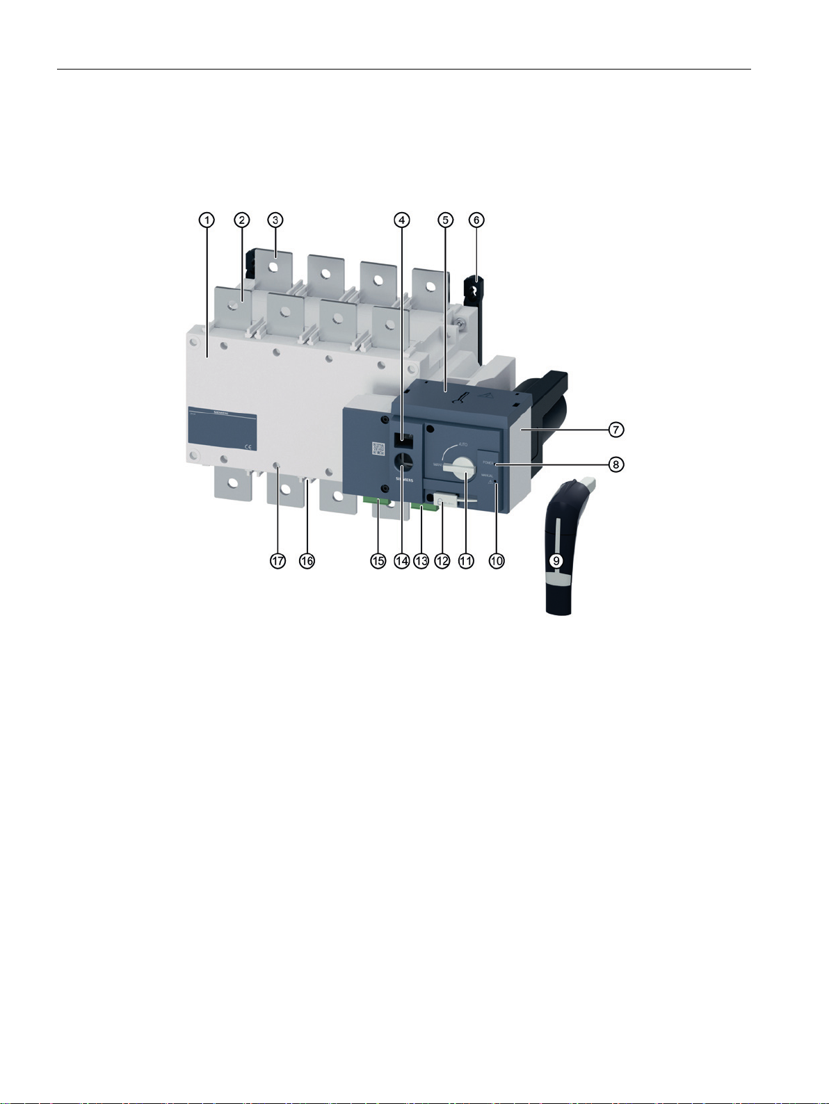
3KC4 remotely operated transfer switching equipment (RTSE):
14 Manual, 08/2017, L1V30368969104A-02
Page 15
Product information
①
⑪
3.1 Product description
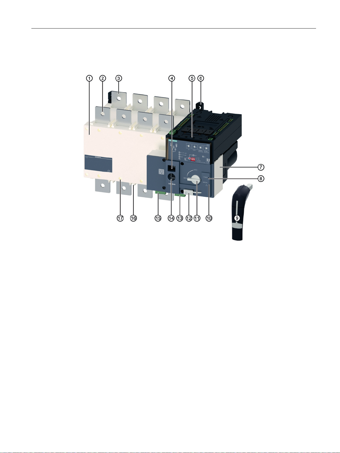
3KC8 automatic transfer switching equipment (ATSE):
Switching unit
②
Connecting terminal of the main source
(source I)
③
Connecting terminal of the alternative source
(source II)
Indication of the selected source: O = Off /
④
I = source I / II = source II
3KC4: Cover of the power supply connection
⑤
3KC8: Electronic module (below this is located the power supply connection)
⑥
Assembly for mounting
⑦
Manual, 08/2017, L1V30368969104A-02
Motor operator
⑧
"Power" LED
⑨
Plug-on handle for manual changeover
⑩
Warning LED
Switch for selecting the mode (Manual /
Automatic)
Padlock assembly
⑫
⑬
4 outputs for
• "Switch position" (I / O / II) indicator
• "Product availability" indicator
⑭
Connection for attachable handle
⑮
5 inputs for
• Positioning commands (I / O / II)
• Activation of remote control
• Priority command for the OFF position
⑯
Mounting channels for terminal protection /
phase barriers
Fixing assembly for terminal plate
⑰
15
Page 16
Product information
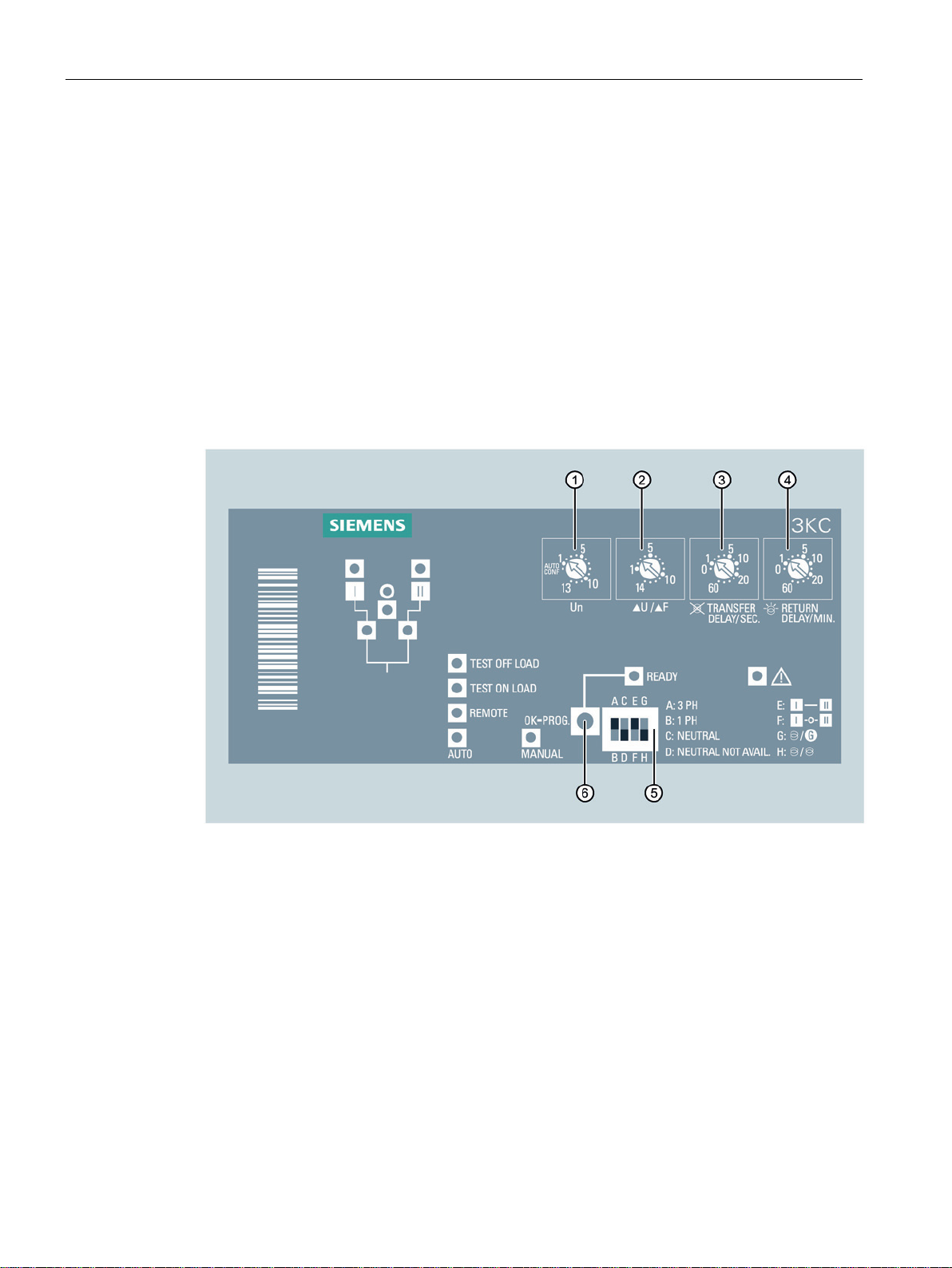
Electronic module
Operator controls
①
②
③
④
⑤
⑥
3.1 Product description
The 3KC8 automatic transfer switching equipment (ATSE) is based on the 3KC4
(RTSE) transfer switching equipment. In contrast to the 3KC4, an electronic module is
additionally integrated into t he 3KC8.
The electronic module enables monitoring of 2 sources as well as automatic transfer
switching. In addition, the electronic module supplies the 3KC8 transfer switching equipment
with power.
The 3KC8 transfer switching equipment is programmed using the electronic module.
You can find more information on programming in the section titled Automatic mode programming of the electronic module (3KC8 only) (Page 132).
Potentiometer 1: Presetting of line voltage/frequency (AutoConf, 1 to 13)
Potentiometer 2: Presetting of voltage/frequency limits (1 to 14)
Potentiometer 3: Presetting of the transfer time delay for source failure (0 to 60 s)
Potentiometer 4: Presetting of the return switching time delay for prioritized source recovered
(0 to 60 min)
DIP switch for configuration
"OK-Prog" pushbutton: Saves the current settings
16 Manual, 08/2017, L1V30368969104A-02
Page 17
Product information
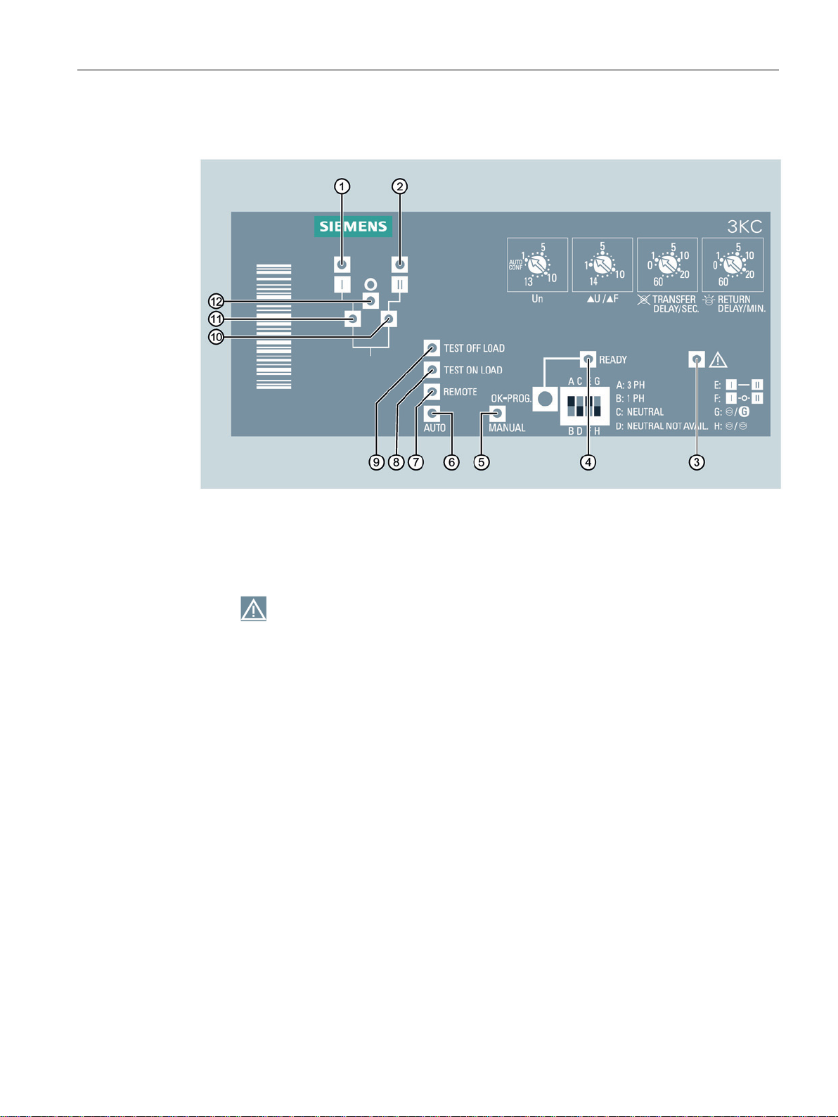
Indicators (LEDs)
Designation
Function
Meaning
①
②
③
④
⑤
⑥
Flashes green if the transfer switching equipment is in
⑦
⑧
3.1 Product description
I Availability
II Availability
READY "Ready" mode Indicates the status of the transfer switching equipment:
MANUAL "Manual" mode Shows a continuous yellow light if the transfer switching
AUTO "Auto" mode Indicates the activity of "Auto" mode:
REMOTE "Remote" mode Shows a continuous yellow light if the transfer switching
TEST
ON LOAD
source I
source II
Fault indicator
"Test on load"
mode
Shows a continuous green light if source I is available
and is within the accepted tolerance.
Shows a continuous green light if source II is available
and is within the accepted tolerance.
• Flashes red if there is an external fault (e.g. incorrect
• Shows a continuous red light if there is an internal
• Shows a continuous green light if the transfer switch-
• Flashes green if defaults haven not been saved or a
equipment is in "Manual" mode.
• Shows a continuous green light if the transfer switch-
•
equipment is in remote mode (controlled via inputs).
Shows a continuous yellow light if the transfer switching
equipment is in "Test on load" mode.
position of the neutral conductor).
fault of the electronic module.
ing equipment is in "Auto" mode and is ready for
source transfer.
new change has been made.
ing equipment is in "Auto" mode and no timer is active.
"Auto" mode and the timer is active.
Manual, 08/2017, L1V30368969104A-02
17
Page 18

Product information
⑨
⑩
⑪
⑫
3.1.2
Current ratings of the 3KC4 and 3KC8 transfer switching equipment
Current rating
Device type
3KC4 (RTSE)
3KC8 (ATSE)
3-pole
4-pole
3-pole
4-pole
3.1 Product description
TEST
OFF LOAD
- Position II indication Shows a continuous green light if the switch is in posi-
- Position I indication Shows a continuous green light if the switch is in posi-
O Position "0" indica-
"Test off load"
mode
tion
Shows a continuous yellow light if the transfer switching
equipment is in "Test off load" mode.
tion II.
tion I.
Shows a continuous yellow light if the switch is in posi-
tion "0" (OFF).
The 3KC4 and 3KC8 transfer switching equipment are available in 10 current ratings. The
table shows the types of transfer switching equipment according to the current ratings:
250 A ✓ ✓ ✓ ✓
400 A ✓ ✓ ✓ ✓
630 A ✓ ✓ ✓ ✓
800 A ✓ ✓ ✓ ✓
1000 A ✓ ✓ ✓ ✓
1250 A ✓ ✓ ✓ ✓
1600 A ✓ ✓ ✓ ✓
2000 A ✓ ✓ ✓ ✓
2500 A ✓ ✓ ✓ ✓
3200 A ✓ ✓ ✓ ✓
18 Manual, 08/2017, L1V30368969104A-02
Page 19
Product information
Designs
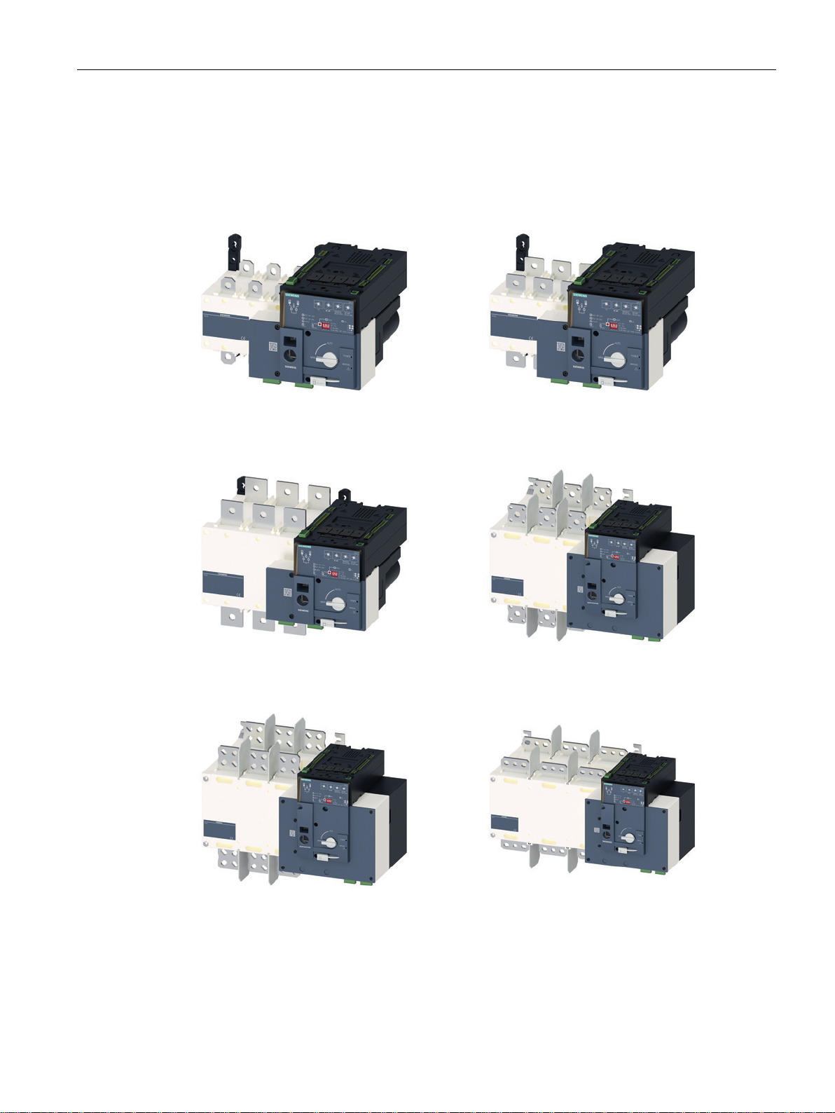
3KC8 250 A
3KC8 400 A
3KC8 630 A
3KC8 800 A / 1000 A
3KC8 1250 A
3KC8 1600 A
3.1 Product description
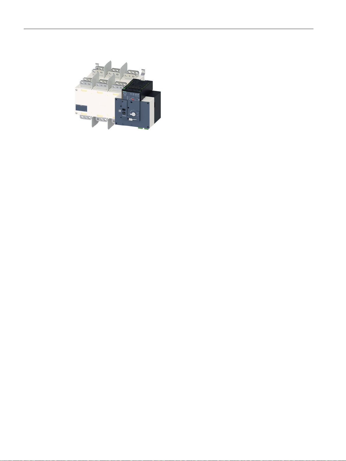
The following figures show the different designs of the transfer switching equipment depicted
according to current rating using the example of the 3KC8 transfer switching equipment:
Manual, 08/2017, L1V30368969104A-02
19
Page 20
Product information
3KC8 2000 A / 2500 A / 3200 A
3.1 Product description
20 Manual, 08/2017, L1V30368969104A-02
Page 21
Product information
3.2
Product family
3.2.1
The product families 3KC4 and 3KC8 from 250 A to 3200 A
Product
family
Type
Designation
Current rating
Number
of poles
O
S
T
E
3.2 Product family
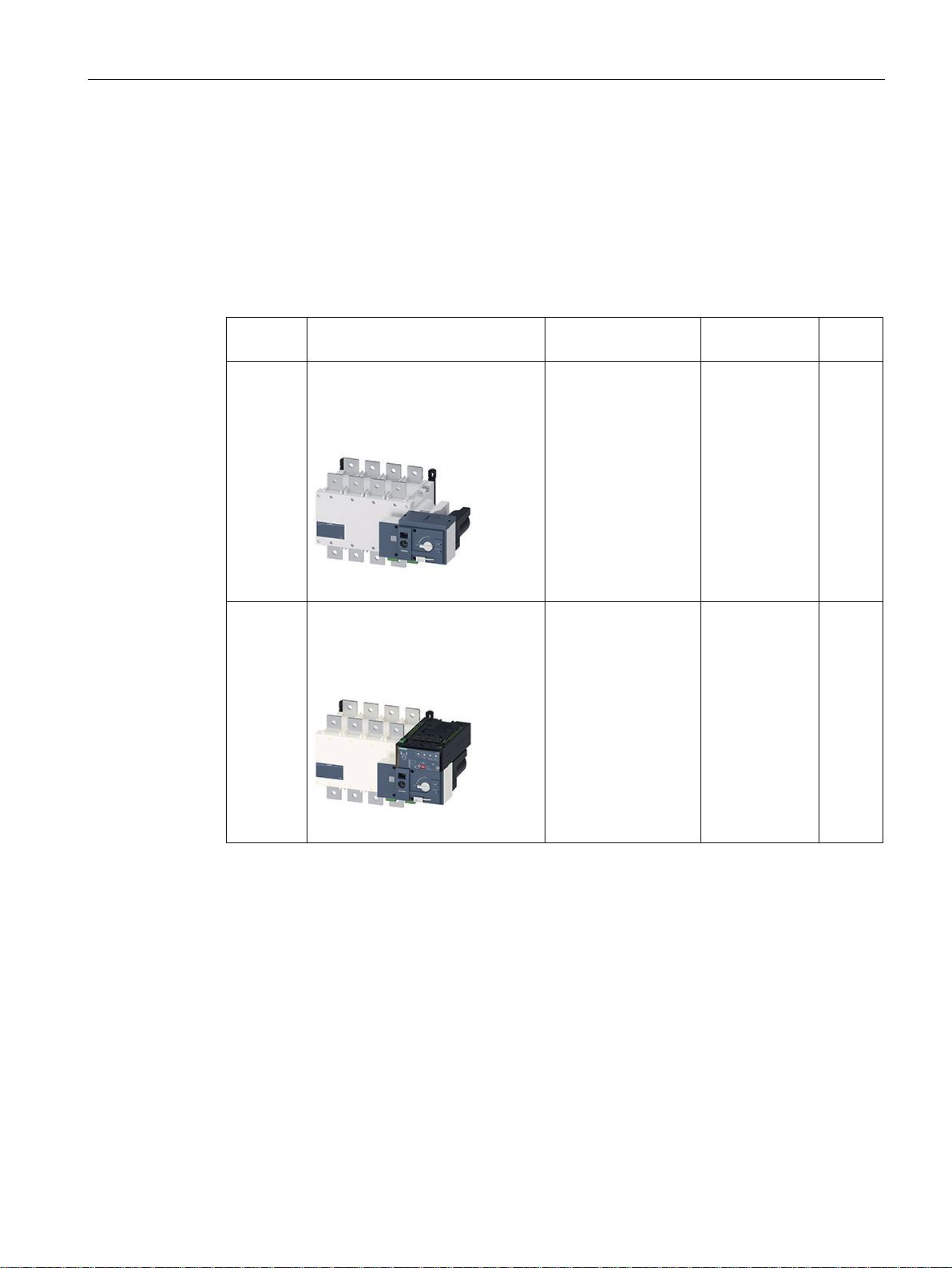
The Siemens product families 3KC4 and 3KC8 from 250 A to 3200 A encompass two types
of transfer switching equipment:
3KC4 Remotely operated transfer switch-
ing equipment
(RTSE)
3KC8 Automatic transfer switching
equipment
(ATSE)
RTSE: Remotely
perated Transfer
witching Equipment
ATSE: Automatic
ransfer Switching
quipment
250 … 3200 A 3; 4
250 … 3200 A 3; 4
Manual, 08/2017, L1V30368969104A-02
21
Page 22

Product information
3.2.2
Use of 3KC4 and 3KC8 transfer switching equipment
Type
Product family
Application areas of transfer switching
Network/network
Network/generator
3.2.3
Properties of the 3KC4 and 3KC8 transfer switching equipment
3.2 Product family
The 3KC4 and 3KC8 transfer switching equipment is used to ensure a continuous supply of
power. The equipment enables reliable transfer between a main source and an alternative
source, thus a power supply is provided by means of an emergency source if the main
source is not available.
The three switch positions of the 3KC4 and 3KC8 series enable maximum stability of the
load power supply, in which case only minimum interruption to the power supply occurs.
Remotely operated transfer switching equipment
(RTSE)
Automatic transfer switching equipment (ATSE)
3KC4 ✓ ✓
3KC8 ✓ ✓
The 3KC4 and 3KC8 transfer switching equipment enables a continuous power supply to be
maintained. The main features are as follows:
● Reliable transfer between two sources with transfer through the OFF position
● Simple installation
● Transfer with open transition
● Minimal interruption in the power supply
● Three- and four-pole designs
● Current ratings from 250 A to 3200 A
● Transfer with the supplied handle
● Extensive accessories and spare parts
● Programming in just 5 steps (3KC8 only)
● Suitability for all load types includi ng ind uc tive loa ds (AC -33)
● Safe maintenance work thanks to locking with padlocks in position 0 (OFF)
● Control signals for starting/stopping the generator, as well as generator and switch device
tests on-load and off-load (3KC8 only)
22 Manual, 08/2017, L1V30368969104A-02
Page 23

Product information
3.2.4
Application areas of the 3KC4 and 3KC8 transfer switching equipment
Service sector
Infrastructure
Industry
3.2 Product family
The 3KC4 and 3KC8 transfer switching equipment can be used in all areas where a
continuous power supply must be ensured.
● Public facilities
● Computing centers (data/server rooms)
● Shopping malls
● Airports
● Subways
● Production lines in continuous operation
● Engine rooms
● Pumps
Manual, 08/2017, L1V30368969104A-02
23
Page 24

Product information
3.2 Product family
24 Manual, 08/2017, L1V30368969104A-02
Page 25

4
Function
3KC4
3KC8
The 3KC4 and 3KC8 transfer switching equipment offers the following functions for
maintaining a power supply:
Remotely operated transfer switch ing (RTSE ) ✓ Automatic transfer switching (ATSE) - ✓
Power supply via 2 inputs (internal dual power supply) - ✓
Remote control (via inputs) ✓ ✓
Network / network applications ✓ ✓
Generator/generator applications ✓
Network / generator applicatio ns ✓
Self-configuration of voltage and frequen cy sett in gs - ✓
Monitoring of voltage and frequency - ✓
Monitoring of the phase sequence - ✓
Configuration using potentiometer and DIP switch - ✓
LED indicator for source availability - ✓
LED indicator for the switch positions - ✓
Test on-load (network/generator application) (via inputs) - ✓
Test off-load (network/generator application) (via inputs) - ✓
Connection for an optional external display - ✓
Setting of the OFF position with priority (via inputs) ✓ ✓
Indication of availability of the motor operator (via output) ✓ ✓
Switch position indication of the transfer switching equipment (via
outputs)
Inhibition of automatic mode (via inputs) - ✓
Inhibition of automatic return transfer to the prioritized sources (via
inputs).
Selection of the prioritized source (network/network application) (via
inputs)
Deactivation of the delay for stabilizing the alternative source (net-
work/generator application)
1)
Possible with the adequate controller
1)
-
1)
✓
✓ ✓
- ✓
- ✓
- ✓
Manual, 08/2017, L1V30368969104A-02
25
Page 26

Functions
26 Manual, 08/2017, L1V30368969104A-02
Page 27
5
5.1
Mounting position
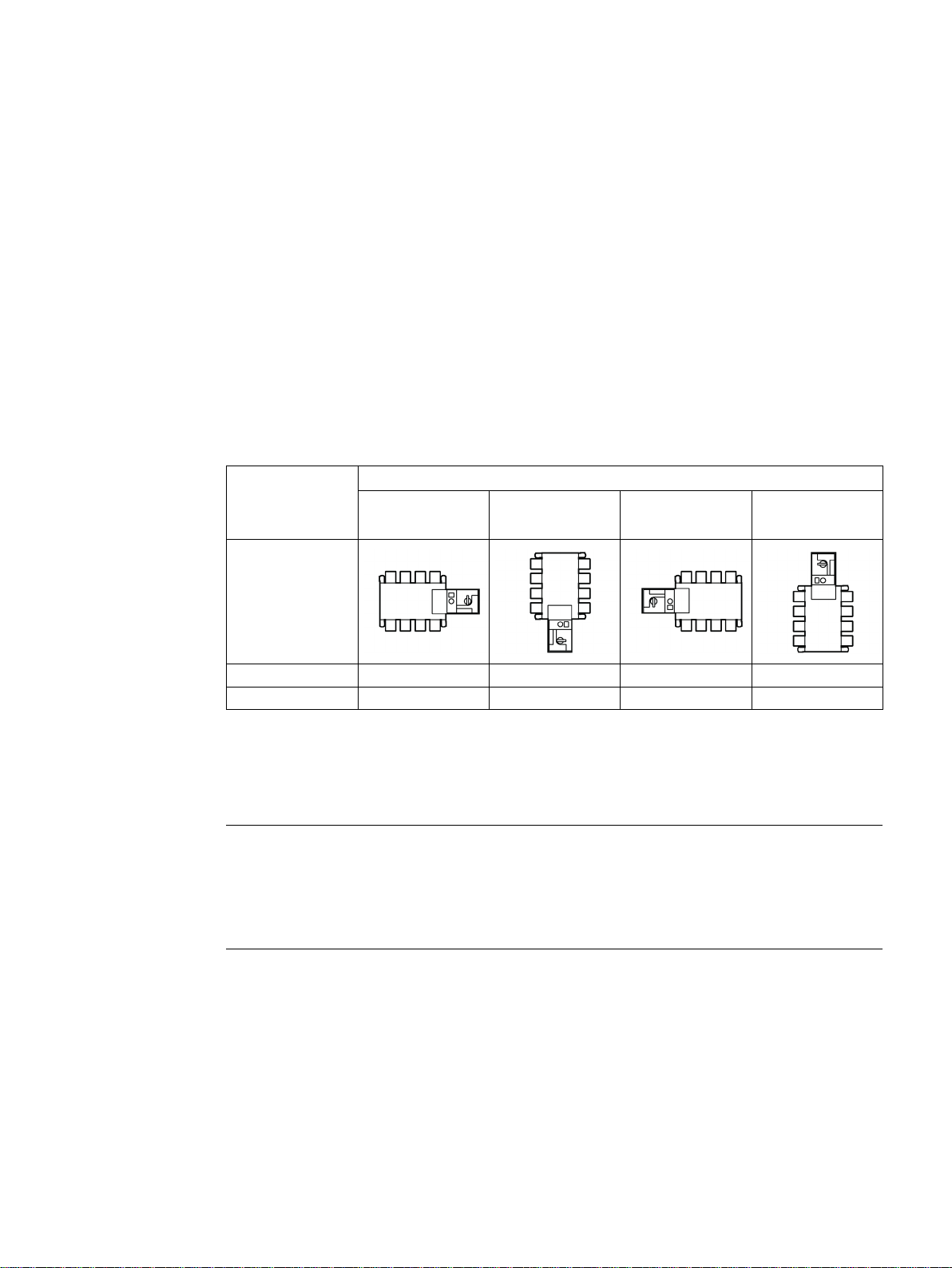
Current rating
Mounting position
Motor operator
right
Motor operator
bottom
Motor operator
left
Motor operator
top
5.2
Installing the 3KC4 and 3KC8 transfer switching equipment
Note
The following content is described in this chapter:
● Mounting positions for the 3KC4 and 3KC8 transfer switching equipment
● Installation of the 3KC4 and 3KC8 transfer switching equipment
250 … 630 A ✓ ✓ ✓ 800 … 3200 A ✓ - ✓ ✓
The 3KC4 transfer switching equipme nt is dep icted in t he foll owi ng inst a llati on ins t ruc tions .
The 3KC8 transfer switching equipment differs from the 3KC4 transfer switching equipment
in its additional electronic module, but it is installed in the same way as the 3KC4 transfer
switching equipment.
Manual, 08/2017, L1V30368969104A-02
27
Page 28
Mounting
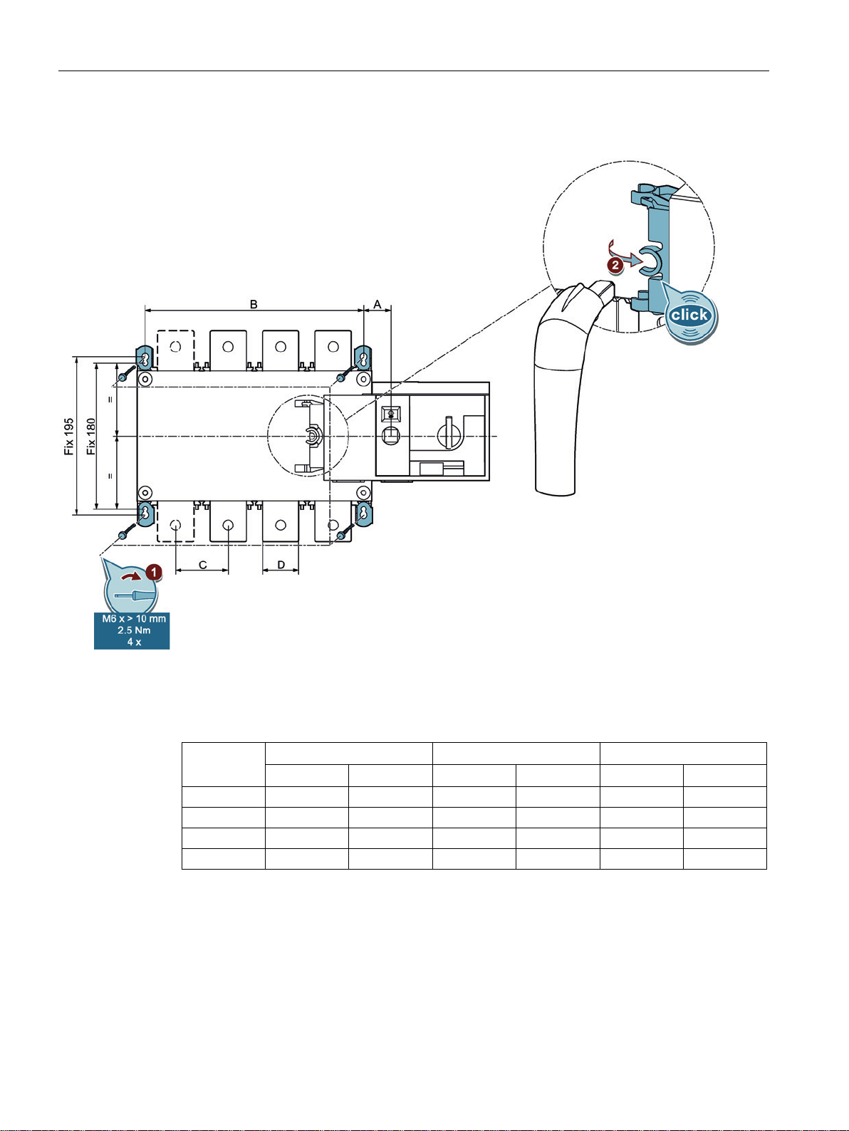
Installing the current ratings 250 A to 630 A
mm
250 A
400 A
630 A
3P
4P
3P
4P
3P
4P
5.2 Installing the 3KC4 and 3KC8 transfer switching equipment
Figure 5-1 Installing the current ratings 250 A to 630 A
The dimensions vary according to the current rating and the number of poles. They can be
found in the table below.
A 35 35 35 35 34 34
B 160 210 160 210 210 270
C 50 50 50 50 65 65
D 25 25 35 35 45 45
Proceed as follows to install the current ratings 250 A to 630 A:
1. Mount the transfer switching equipment with four bolts in the desired position as shown in
the figure (see also the section titled Mounting position (Page 27)).
2. Fasten the holder for the handle on the transfer switching equipment, and insert the
handle into the holder.
The handle and its holder are included in the scope of supply. The bolts are not included with
the 3KC automatic transfer equipment.
28 Manual, 08/2017, L1V30368969104A-02
Page 29
Mounting
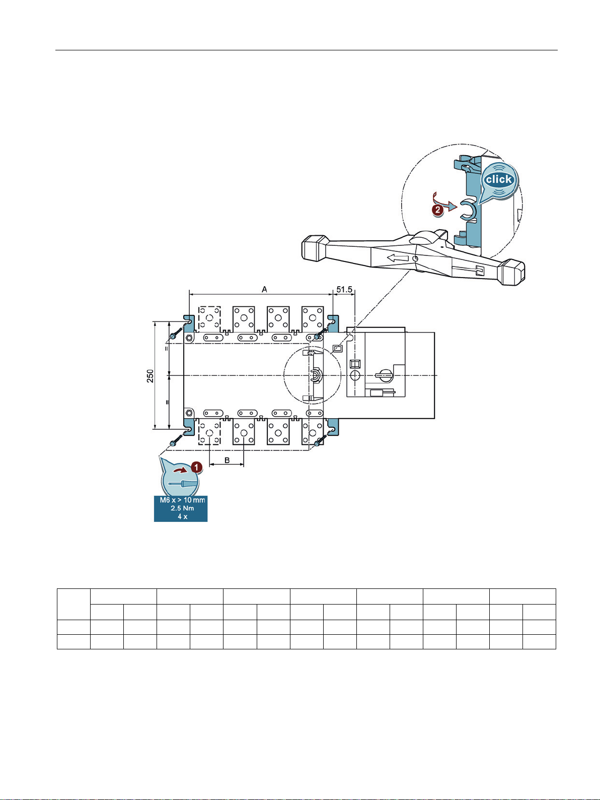
Installing the current ratings 800 A to 3200 A
mm
800 A
1000 A
1250 A
1600 A
2000 A
2500
3200 A
3P
4P
3P
4P
3P
4P
3P
4P
3P
4P
3P
4P
3P
4P
5.2 Installing the 3KC4 and 3KC8 transfer switching equipment
Proceed as follows to install the 3KC4 and 3KC8 transfer switching equipment of current
ratings 800 A to 3200 A:
Figure 5-2 Installing the current ratings 800 A to 3200 A
The dimensions vary according to the current rating and the number of poles. They can be
found in the table below.
A 255 335 255 335 255 335 347 467 347 467 347 467 347 467
B 80 80 80 80 80 80 120 120 120 120 120 120 120 120
The installation steps are identical to those for installing the current ratings 250 A to 630 A,
see above.
Manual, 08/2017, L1V30368969104A-02
29
Page 30
Mounting
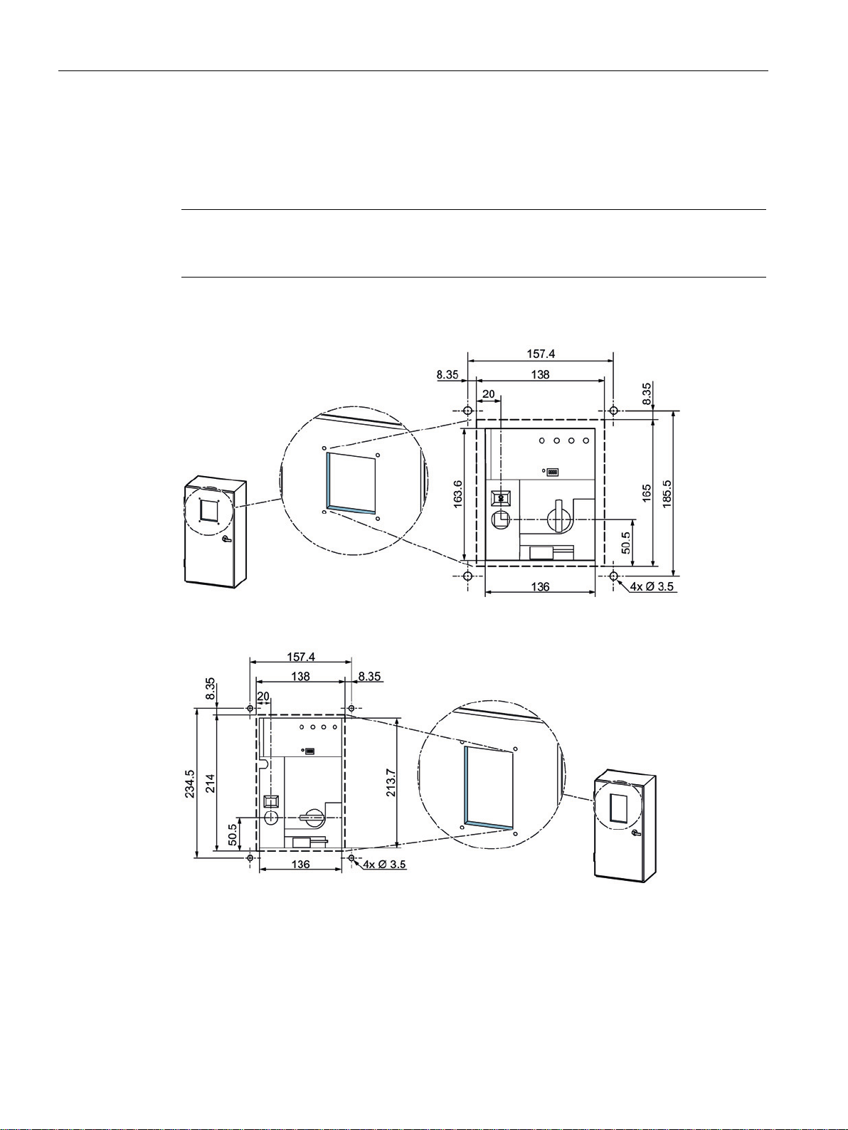
5.3
Dimensions of the cover frame for door cut-out
Note
Current ratings 250 A to 630 A
Current ratings 800 A to 3200 A
5.3 Dimensions of the cover frame for door cut-out
The following figures show the dimensions of the cover frame for door cut-out for the 3KC4
and 3KC8 transfer switching equipment.
On the 3KC8 transfer switching equipment there is an additional electronic module that
enables source monitoring.
Figure 5-3 Dimensions of the cover frame for door cutout 800 A to 3200 A
30 Manual, 08/2017, L1V30368969104A-02
Page 31

6
6.1
Network types
NOTICE
Possible damage to the device
The following content is described in this chapter:
● Network types
● Connection to the source (connecting terminals, connection instructions for each current
rating, required accessories)
● Inputs and outputs of the motor operator and accessories
● Inputs and outputs of the electronic module
● Connection of the transfer switching equipment (motor operator, electronic module,
required accessories)
The 3KC4 and 3KC8 transfer switching equipment can be connected to the following
network types:
● Three-phase 4-wire network with 3 phases with neutral (3PH + N)
● Three-phase 3-wire network with 3 phases without neutral (3PH)
● Single-phase network with 1 phase and neutral (1PH + N)
The product is designed for a rated impulse voltage resistance U
circuit and 4 kV for the electronics and/or motor unit. The dual power supply (DPS)
accessory is designed for a rated impulse voltage resistance U
autotransformer accessory is designed for 2.5 kV.
When using the product in an application in whic h over v oltages of > 4 kV or > 2.5 kV can
occur, suitable measures must additionally be taken to limit these overvoltages to no more
than 4 kV or 2.5 kV, respectively.
of 12 kV for the main
imp
of 4 kV, and the
imp
Manual, 08/2017, L1V30368969104A-02
31
Page 32

Connection
6.1.1
Three-phase 4-wire network with neutral (3PH + N)
6.1.1.1
Circuit diagram for the 3KC4 transfer switching equipment - 4-pole transfer switching equipment
Note
6.1 Network types
The 3KC4 and 3KC8 transfer switching equipment can be used in a network comprising
three phases and a neutral conductor.
Figure 6-1 Three-phase 4-wire network with neutral for the 3KC4 transfer switching equipment
F1 1 x 3NW6004-1
1 x 3NW7013
4 A, gG
For the power supply of the transfer switching equipment, the dual power supply accessory
3KC9625-1 is required. You can find a detailed description in the section titled Mounting and
connecting the dual power supply (DPS) (Page 77).
The F1 fuses must be installed as closely as possible to the tap.
32 Manual, 08/2017, L1V30368969104A-02
Page 33

Connection
6.1.1.2
Circuit diagram for the 3KC8 transfer switching equipment - 4-pole transfer switching equipment
6.1.2
Three-phase 3-wire network without neutral (3PH)
Note
6.1 Network types
Figure 6-2 Three-phase 4-wire network with neutral for the 3KC8 transfer switching equipment
The power supply kit accessories 3KC9830-, 3KC9831- can be used for the power supply of
the transfer switching equipment. You can find a detailed description in the section titled
Connecting power supply kit 3KC9830-, 3KC9831- (4-pole) (Page 92).
The dual power supply (DPS) accessory is not required with the 3KC8 transfer switching
equipment since it is supplied with power via two inputs of the electronic module.
The 3KC4 and 3KC8 transfer switching equipment can be used in a network comprising 3
phases. It can be used both in networks with balanced load, as well as in networks with
unbalanced load.
The fictitiously generated fourth pole is used only for the power supply of the transfer
switching equipment and mus t not be run to the main load.
Manual, 08/2017, L1V30368969104A-02
33
Page 34

Connection
6.1.2.1
Circuit diagram for the 3KC4 transfer switching equipment - 3-pole transfer switching equipment
Note
6.1 Network types
Figure 6-3 Three-phase 3-wire network without neutral for the 3KC4 transfer switching equipment
F1 2 x 3NW6002-1
1 x 3NW7023
F2 1 x 3NW6004-1
1 x 3NW7013
2 A, gG
4 A, gG
With this arrangement there is no neutral conductor available. For this reason, the following
optional accessories can/must be used for establishing this network:
● 2 x autotransformer 3KC9824-1. For information, see the section titled Ins tal ling a nd
connecting an autotransformer (400 V / 230 V) (Page 79).
● 1 x dual power supply 3KC9625-1. For information, see the section titled Mounting and
connecting the dual power supply (DPS) (Page 77).
The F1 fuses must be installed as closely as possible to the tap.
The F2 fuses must be fitted as closely as possible to the output of the autotransformer.
34 Manual, 08/2017, L1V30368969104A-02
Page 35

Connection
6.1.2.2
Circuit diagram for the 3KC8 transfer switching equipment - 4-pole transfer switching equipment
Note
6.1 Network types
Figure 6-4 Three-phase 3-wire network without neutral for the 3KC8 transfer switching equipment
(4-pole)
F1 2 x 3NW6002-1
1 x 3NW7023
F2 1 x 3NW6004-1
1 x 3NW7013
2 A, gG
4 A, gG
With this arrangement there is no neutral conductor available. For this reason, the following
optional accessories can be used for establishing this network:
● 2 x autotransformer 3KC9824-1. For information, see the section titled Ins tal ling a nd
connecting an autotransformer (400 V / 230 V) (Page 79).
● For the power supply: Power supply kit 3KC9830-, 3KC9831-. For information, see the
section titled Connecting power supply kit 3KC9830-, 3KC9 83 1- (4-pole) (Page 92).
The F1 fuses must be installed as closely as possible to the tap.
The F2 fuses must be fitted as closely as possible to the output of the autotransformer.
The dual power supply (DPS) accessory is not required with the 3KC8 transfer switching
equipment since it is supplied with power via two inputs of the electronic module.
Manual, 08/2017, L1V30368969104A-02
35
Page 36

Connection
6.1.2.3
Circuit diagram for the 3KC8 transfer switching equipment - 3-pole transfer switching equipment
6.1 Network types
Figure 6-5 Three-phase 3-wire network without neutral for the 3KC8 transfer switching equipment
(3-pole)
F1 2 x 3NW6002-1
1 x 3NW7023
F2 1 x 3NW6004-1
1 x 3NW7013
2 A, gG
4 A, gG
With this arrangement there is no neutral conductor available. For this reason, the following
optional accessories can/must be used for establishing this network:
● 2 x autotransformer 3KC9824-1. For information, see the section titled Ins tal ling a nd
connecting an autotransformer (400 V / 230 V) (Page 79).
● The auxiliary conductor terminal kit is required in the case of the 3-pole variant for
connecting the electronic module, and it must be mounted before connection to the
source. See the section titled Connecting the auxiliary conductor terminal 3KC9822-,
3KC9832- for a three-phase 3-wire network (3-pole) (Page 95).
The dual power supply (DPS) accessory is not required with the 3KC8 transfer switching
equipment since it is supplied with power via two inputs of the electronic module.
36 Manual, 08/2017, L1V30368969104A-02
Page 37

Connection
6.1.3
Single-phase network with neutral (1PH + N)
6.1.3.1
Circuit diagram for the 3KC4 transfer switching equipment - 3-pole transfer switching equipment
Note
6.1 Network types
The 3KC4 and 3KC8 transfer switching equipment can be used in a single-p has e networ k
comprising one phase and a neutral conductor. Since there is no 2-pole design available for
the transfer switching equipment, the 3KC4 and 3KC8 transfer switching equipment in 3-pole
design is the best choice.
Figure 6-6 Single-phase network without neutra l for 3KC4 transf er switc hing equ ipm ent
F1 1 x 3NW6004-1
For the power supply of the 3KC4 transfer switching equipment, the dual power supply
accessory 3KC9625-1 is required. You can find a detailed description of this in the section
titled Mounting and connecting the dual power supply (DPS) (Page 77).
The F1 fuses must be installed as closely as possible to the tap.
Manual, 08/2017, L1V30368969104A-02
4 A, gG
1 x 3NW7013
37
Page 38

Connection
6.1.3.2
Circuit diagram for the 3KC8 transfer switching equipment - 3-pole transfer switching equipment
Note
6.1 Network types
* No fuse required if the power supply kit accessories 3KC9833-, 3KC9834- are used
Figure 6-7 Single-phase system without 3KC 8 transfer sw itc hin g equipment
F1 1 x 3NW6004-1
1 x 3NW7013
4 A, gG
The dual power supply (DPS) accessory is not required with the 3KC8 transfer switching
equipment since it is supplied with power via two inputs of the electronic module. Before
connecting, the pins 101/102 and 201/202 must be connected to the main circuit. This can
be done most easily with the 3KC9833-, 3KC9834- power supply kit. See the section titled
Connecting power supply kit 3KC9833-, 3KC9834- for single-phase network (Page 98) in this
regard.
The F1 fuses must be installed as closely as possible to the tap.
38 Manual, 08/2017, L1V30368969104A-02
Page 39

Connection
6.2
Connecting the main circuit
6.2.1
Connecting terminals of the transfer switching equipment
Connecting terminals for current ratings 250 A to 630 A
Connecting terminals for current ratings 800 A to 1600 A
Connecting terminals for current ratings 2000 A to 3200 A
2000 A to 3200 A
6.2 Connecting the main circuit
In the following chapter, you will find a description of the connection options for the 3KC4
and 3KC8 transfer switching equipment.
The connecting terminals of the 3KC4 and 3KC8 transfer switching equipment differ
depending on the current rating. The different connecting terminals are shown below.
250 A
800 A – 1000 A
400 A
1250 A
630 A
1600 A
Manual, 08/2017, L1V30368969104A-02
39
Page 40

Connection
6.2.2
Load connection
6.2.3
Arrangement of the power supply systems
Note
NOTICE
Incorrect connection in the case of network/generator applications of the 3KC8 transfer
switching equipme nt
6.2 Connecting the main circuit
The following figure shows the two fundamentally possible arrangements for the connected
load. It can be connected at the top or bottom.
Figure 6-8 Arrangements for load connection
Since both the 3KC4 and the 3KC8 have a flat connector, they can be connected to the
power supply system using cable lugs or busbars.
Transfer switching equipment of 2000 A and higher is connected using the optionally
available copper bar connection kit.
The transfer switching equipment for 2000 A and higher comprises 2 switches (switch 1 and
switch 2) in each case. These must be bridged using the copper bar connection kit.
The main current source must be connected to switch 1. Only then is the transfer switching
equipment functional. Connection of the generator to switch 2 is absolutely necessary for
controlling the generator.
40 Manual, 08/2017, L1V30368969104A-02
Page 41

Connection
Connecting the 3KC8 transfer switching equipment
Note
6.2 Connecting the main circuit
With network/network applications, any arrangement of the connection can be selected.
With the 3KC8 transfer switching equipment, prioritization of the source can be implemented
via the corresponding inputs. For information, see the section titled Functions of the control
inputs for network / generator application (Page 119).
Before you connect the 3KC8 transfer switching equipment to the power supply systems,
you must attach the corresponding accessories to make the electronic module functional.
The required accessories depend on the current rating and the network type. Observe the
information in the section titled Connecting the inputs and outputs of the electronic module
(3KC8 only) (Page 89) before connecting the transfer switching equipment to the power
supply systems.
Figure 6-9 Line-side connection of the main circuit with the 3KC8 transfer switching equipment
Manual, 08/2017, L1V30368969104A-02
41
Page 42

Connection
6.2.4
Connection of transfer switching equipment for current ratings 250 A to 1600 A
6.2.4.1
Connecting bridging bars on the load side
WARNING
Hazardous voltage!
Mounting bridging bars for current ratings 250 A to 630 A
6.2 Connecting the main circuit
The connection of current ratings 250 A to 1600 A to the main circuit is described in the
following section.
To connect the 3KC4 and 3KC8 transfer switching equipment properly, you must first mount
the bridging bar accessories on the load side. The steps listed below describe the mounting
of the bridging bars and connection to the power supply systems.
Ensure there is no live voltage before beginning to mount the bridging bars.
Current ratings 250 A to 1600 A require bridging bars. These serve as a bridge for the loadside connection and they can be mounted either on the top or bottom of the transfer
switching equipment.
The bridging bars are not included with the transfer switch and must be ordered as
accessories.
Figure 6-10 Bridging bar current ratings 250 A to 630 A
42 Manual, 08/2017, L1V30368969104A-02
Figure 6-11 Bridging bar current ratings 800 A to 1600 A
The following steps are necessary for mounting the bridging bars on the transfer switching
equipment. Refer to the table for information about the bolts, tools, and tightening torques.
The bolts are not included with the transfer switch. You can find more detailed information on
the bridging bars in the section titled Bridging bars (Page 154).
Page 43

Connection
Requirements
Procedure
Current rating
Note
completely
6.2 Connecting the main circuit
● Power supply is switched off
● Transfer switching equipment is in the "Manual" position
Figure 6-12 Mounting bridging bars for current ratings 250 A to 630 A
250 A M10 x 20 mm 17 20 ... 26
400 A M10 x 25 mm
630 A M12 x 30 mm 19 40 ... 45
1. Position the bridging bar on the connecting terminal.
2. Fix the first half of the bridging bar to the connecting terminal with the bolt and washer.
3. Fix the second half of the bridging bar to the connecting terminal with the bolt and
washer.
The two halves of the bridging bar must come into contact
before work step 4.
4. Connect the two parts of the bridging bar with 1 bolt, 2 washer s and 1 nut in accordanc e
with the figure.
Manual, 08/2017, L1V30368969104A-02
43
Page 44

Connection
Mounting bridging bars for current ratings 800 A to 1600 A
Requirements
Procedure
6.2 Connecting the main circuit
The following steps are necessary for mounting the bridging bars on the transfer switching
equipment. Refer to the table for information about the bolts, tools, and tightening torques.
The bolts for mounting the bridging bars are included in the scope of supply.
Bolts with washers and nuts are additionally required in the following quantities for fixing the
bridging bars to the connecting terminal:
● 4 x for current ratings 800 A to 1250 A
● 2 x for current rating 1600 A
● Power supply is switched off
● Transfer switching equipment is in the "Manual" position
Figure 6-13 Mounting bridging bars for current ratings 800 A to 1600 A
44 Manual, 08/2017, L1V30368969104A-02
Page 45

Connection
Current rating
Note
completely
6.2 Connecting the main circuit
800 A ... 1000 A M8 x 35 mm 13 8.3 ... 13
1250 A M10 x 40 mm 17 20 ... 26
1600 A M12 x 45 mm 19 40 ... 45
1. Position the bridging bar on the connecting terminal.
2. Fix the first half of the bridging bar to the connecting terminal.
– For current ratings of 800 A to 1250 A with 4 bolts, 8 washers, and 4 nuts.
– For current ratings of 1600 A with 2 bolts, 4 washers, and 2 nuts.
3. Fix the second half of the bridging bar to the connecting terminal.
– For current ratings of 800 A to 1250 A with 4 bolts, 8 washers, and 4 nuts.
– For current ratings of 1600 A with 2 bolts, 4 washers, and 2 nuts.
The two halves of the bridging bar must come into contact
before work step 4.
4. Connect the two parts of the bridging bar with the bolts supplied.
Manual, 08/2017, L1V30368969104A-02
45
Page 46

Connection
6.2.4.2
Connecting current ratings 250 A to 1600 A to the main circuit
WARNING
Hazardous voltage!
NOTICE
System damage
Note
Using bridging bars
before
Note
6.2 Connecting the main circuit
The following steps are necessary for connecting the transfer switching equipment to the
main circuit. Refer to the respective table for information about the permissible copper
connections, required tools, and tightening torques.
Ensure there is no live voltage before connecting the transfer switching equipment to the
main circuit.
Connect the power supply systems with phase equality.
Mount the bridging bars
circuit. For information, see the section titled
connecting the transfer switching equipment to the main
Connecting bridging bars on the load side
(Page 42).
If you are using the 3KC8 transfer switching equipment, mount the corresponding
accessories for the electronic module (see the section titled Connecting the inputs and
outputs of the electronic module (3KC8 only) (Page 89)).
46 Manual, 08/2017, L1V30368969104A-02
Page 47

Connection
Current ratings 250 A to 630 A
Requirements
Procedure
Current
rating
6.2 Connecting the main circuit
● Main circuit is disconnected
● Transfer switching equipment is in the "Manual" position
Figure 6-14 Connecting current ratings 250 A to 630 A
250 A 1 x 30 x 4 ... 1 x 32 x 5 120 ... 150 M10 20 ... 26
400 A 1 x 30 x 8 ... 1 x 32 x 8 240 M10 20 ... 26
630 A 2 x 40 x 5 ... 2 x 50 x 8 2 x 185 ... 2 x 300 M12 40 ... 45
1. Mount the cable lug or the busbar according to the figure.
2. Secure the connection with 1 bolt, 2 washers, and 1 nut on the cable lug or the busbar.
Manual, 08/2017, L1V30368969104A-02
47
Page 48

Connection
Current ratings 800 A to 1600 A
Requirements
Procedure
Current rating
6.2 Connecting the main circuit
● Main circuit is disconnected
● Transfer switching equipment is in the "Manual" position
Figure 6-15 Connecting current ratings 800 A to 1600 A
800 A 2 x 50 x 5 2 x 240 ... 2 x 300 M8 8.3 ... 13
1000 A 2 x 60 x 5 4 x 185 M8 8.3 ... 13
1250 A 2 x 60 x 7 4 x 185 M10 20 ... 26
1600 A 2 x 100 x 5 6 x 185 M12 40 ... 45
1. Mount the cable lug or the busbar according to the figure.
2. Secure the connection with a cable lug or the busbar.
– For current ratings of 800 A to 1250 A with 4 bolts, 8 washers, and 4 nuts in each
case.
– For current ratings of 1600 A with 2 bolts, 4 washers, and 2 nuts.
48 Manual, 08/2017, L1V30368969104A-02
Page 49

Connection
6.2.5
Connection of transfer switching equipment for current ratings 2000 A to 3200 A
6.2.5.1
Copper bar connection kit
Overview of the copper bar connection kit
6.2 Connecting the main circuit
The connection of current ratings 2000 A to 3200 A to the main circuit is described in the
following section.
So that you can connect the 3KC4 and 3KC8 transfer switching equipment to the power
supply systems properly, you must first mount the copper bar connection kit accessory. The
steps listed below describe the mounting of the copper bar connection kit and connection to
the power supply systems.
For current ratings 2000 A to 3200 A, the copper bar connection kit may be mounted on the
line or load side, depending on the connection type. This is not fully included with the
transfer switch and must be ordered separately.
The copper bar connection kit is made up of 5 separately available parts. The different
components of the copper bar connection kit enable a host of connection options.
Figure 6-16 Connection, part A, (3KC9811-0, included in the scope of supply for current rating
3200 A)
Figure 6-17 Bolt set, part B, 45 mm (3KC9811-1)
Figure 6-18 Bolt set, part B, 35 mm short length (3KC9811-2)
Manual, 08/2017, L1V30368969104A-02
49
Page 50

Connection
Note
6.2 Connecting the main circuit
Figure 6-19 T piece, part C (3KC9811-3)
Figure 6-20 Bracket, part D (3KC9811-4)
Figure 6-21 Bridging bar, part E (3KC9811-8)
The required bolts for the T piece (3KC9811-3), the bracket (3KC9811-4), and the bridging
bar (3KC9811-8) are already included with the transfer switch.
The different solutions offered by the copper bar connection kit for current ratings 2000 A to
3200 A are shown below.
With the 3KC4 and 3KC8 transfer switching equipment of current rating 3200 A, the
connection, part A (3KC9811-0) is already included with the transfer switch and must be
mounted on the 3200 A transfer switching equipment on the line and load side.
50 Manual, 08/2017, L1V30368969104A-02
Page 51

Connection
Connection options
Version
Position of the connection
Current rating
Fig.
6.2 Connecting the main circuit
The following connections are possible with the copper bar connection kit:
1 Line side
2 Line side 3200 A
3 Line side 2000 A … 2500 A
2000 A … 2500 A
4 Line side 2000 A … 2500 A
5 Line side 3200 A (2900 A max.)
Manual, 08/2017, L1V30368969104A-02
51
Page 52

Connection
Version
Position of the connection
Current rating
Fig.
6.2 Connecting the main circuit
6 Line side 3200 A
7 Load side 2000 A … 2500 A
8 Load side 3200 A
9 Load side 2000 A … 2500 A
52 Manual, 08/2017, L1V30368969104A-02
Page 53

Connection
Version
Position of the connection
Current rating
Fig.
6.2 Connecting the main circuit
10 Load side 2000 A … 2500 A
11 Load side 3200 A
12 Load side 3200 A
Manual, 08/2017, L1V30368969104A-02
53
Page 54

Connection
Dimensions of the 3KC4 and 3KC8 transfer switching equipment with copper bar connection kit
Dimensions version 1
Dimensions version 2
Dimensions of version 3 to 8
6.2 Connecting the main circuit
Use of the copper bar connection kit changes the dimensions of the 3KC4 and 3KC8 transfer
switching equipment.
Figure 6-22 Dimensions with copper bar connection kit, version 1
Figure 6-23 Dimensions with copper bar connection kit, version 2
Figure 6-24 Dimensions with copper bar connection kit, versions 3 to 8
54 Manual, 08/2017, L1V30368969104A-02
Page 55

Connection
Dimensions of version 9 to 12
6.2.5.2
Connecting current ratings 2000 A to 3200 A to the main circuit (on the line side)
WARNING
Hazardous voltage!
NOTICE
System damage
Note
Busbar requirements
6.2 Connecting the main circuit
Figure 6-25 Dimensions with copper bar connection kit, versions 9 to 12
The connection of current ratings 2000 A to 3200 A on the line side to the main circuit is
described in the following section. Different connection variants are possible here (versions
listed in the form of a table in the section titled Copper bar connection kit (Page 49)).
Ensure there is no live voltage before connecting the transfer switching equipment to the
main circuit.
Connect the power supply systems with phase equality.
If you are using the 3KC8 transfer switching equipment, mount the corresponding
accessories for the electronic module. For information, see the section titled Connecting the
inputs and outputs of the electronic module (3KC8 only) (Page 89).
Manual, 08/2017, L1V30368969104A-02
Busbars with the following minimum dimensions must be used for line-side connection:
● Minimum copper busbar for I
● Minimum copper busbar for I
● Minimum copper busbar for I
2000 A = 3 x 100 x 5 mm
th
2500 A = 4 x 100 x 5 mm
th
3200 A = 3 x 100 x 10 mm
th
55
Page 56

Connection
Mounting and connecting version 1 (2000 A to 2500 A)
Number of poles
Current rating
Bolt set, part B, 35 mm
(3KC9811-2)
1)
Contains only the quantity for line-side connectio n
6.2 Connecting the main circuit
Figure 6-26 Connecting busbar, version 1
The following components of the copper bar connection kit are required in the following
quantities for these versions:
Figure 6-27 Bolt set, part B, 35 mm short length, 3KC9811-2
3-pole 2000 A … 2500 A 6 x
4-pole 2000 A … 2500 A 8 x
1)
This variant is connected directly to the power supply systems via the busbars.
56 Manual, 08/2017, L1V30368969104A-02
Page 57

Connection
Requirements
Procedure
6.2 Connecting the main circuit
● Main circuit is disconnected
● Transfer switching equipment is in the "Manual" position
1. Mount one busbar on each connecting terminal of the 3KC4 or 3KC8 transfer switching
equipment with 6 bolts and 6 washers of the bolt set, part B, 35 mm (3KC9811-2).
Figure 6-28 Connecting busbar, version 1
Manual, 08/2017, L1V30368969104A-02
57
Page 58

Connection
Mounting and connecting version 2 (3200 A)
Number of
poles
Current rating
Bolt set, part B, 35 mm
(3KC9811-2)
1)
Bolt set, part B, 45 mm
(3KC9811-1)
1)
6.2 Connecting the main circuit
Figure 6-29 Connecting busbar, version 2
The following components of the copper bar connection kit are required in the following
quantities for these versions:
Figure 6-30 Bolt set, part B, 35 mm short length, 3KC9811-2
Figure 6-31 Bolt set, part B, 45 mm, 3KC9811-1
3-pole 3200 A 3 x 3 x
4-pole 3200 A 4 x 4 x
1) Contains only the quantity for line-side connec tio n
This variant is connected directly to the power supply systems via the busbars. Part A is
included with the transfer switch and must be secured.
58 Manual, 08/2017, L1V30368969104A-02
Page 59

Connection
Requirements
Procedure
6.2 Connecting the main circuit
● Main circuit is disconnected
● Transfer switching equipment is in the "Manual" position
1. Insert the connection, part A (3KC9811-0, already included with the transfer switch)
between the two connecting terminals.
Figure 6-32 Inserting connection, part A
2. Mount 2 busbars with 3 bolts and 3 washers of the bolt set, part B, 45 mm (3KC9811-1)
on the front connecting terminal.
3. Mount 1 busbar with 3 bolts and 3 washers of the bolt set, part B, 35 mm (3KC9811-2) on
the rear connecting terminal.
Figure 6-33 Connecting busbar, version 2
Manual, 08/2017, L1V30368969104A-02
59
Page 60

Connection
Mounting and connecting version 3 to 6 (2000 A to 3200 A)
6.2 Connecting the main circuit
Version 3: 2000 A to 2500 A
Version 5: 2900 A max.
Version 4: 2000 A to 2500 A
Version 6: 3200 A
60 Manual, 08/2017, L1V30368969104A-02
Page 61

Connection
Number of
poles
Current rating
Connection, part A
(3KC9811-0)
1)
T piece, part C
(3KC9811-3)
1)
Bracket, part D
(3KC9811-4)
1)
6.2 Connecting the main circuit
The following components of the copper bar connection kit are required for these versions:
Figure 6-34 Connection, part A, 3KC9811-0 (already included with the transfer switch for 3200 A)
Figure 6-35 T piece, part C 3KC9811-3
Figure 6-36 Bracket, part D, 3KC9811-4
3-pole 2000 A …
6 x 6 x 6 x
2500 A
3-pole 3200 A Included with the transfer
switch
4-pole 2000 A …
8 x 8 x 8 x
2500 A
4-pole 3200 A Included with the transfer
switch
1) Contains only the quantity for line-side connec tio n
6 x 6 x
8 x 8 x
Manual, 08/2017, L1V30368969104A-02
61
Page 62

Connection
Mounting version 3 to 6 of copper bar connection kit
6.2 Connecting the main circuit
1. Insert the connection, part A (3KC9811-0) between the two connecting terminals.
Figure 6-37 Inserting connection, part A
2. Mount the bracket, part D (3KC9811-4), with the supplied bolts on the outsi de of the
connecting terminals to secure the connection, part A.
Figure 6-38 Mounting bracket, part D
3. Position the T piece, part C (3KC9811-3) with the supplied bolts as shown in the figure on
top of the already mounted parts A and D.
Figure 6-39 Mounting the T piece
62 Manual, 08/2017, L1V30368969104A-02
Page 63

Connection
Connecting versions 3 to 6
Requirements
Procedure
Version
Bolt
Washer
Nut
6.2 Connecting the main circuit
Versions 3 and 5, as well as versions 4 and 6, are connected to the power supply systems in
two different ways:
● Version 3 and 5: Vertically aligned
● Version 4 and 6: Horizontally aligned
● Main circuit is disconnected
● Transfer switching equipment is in the "Manual" position
● Copper bar connection kit is mounted
The bolt set required for mounting is not included with the transfer switch. You can find the
bolt set requirements in the following table:
3 (vertical)
2000 … 2500 A
4 (horizontal)
2000 … 2500 A
5 (vertical)
2900 A
6 (horizontal)
3200 A
3 x H M12-55 6.8 6 x 3 x
5 x H M12-55 6.8 10 x 5 x
3 x H M12-65 6.8 6 x 3 x
5 x H M12-65 6.8 10 x 5 x
Manual, 08/2017, L1V30368969104A-02
63
Page 64

Connection
6.2 Connecting the main circuit
1. Mount the busbar on the transfer switching equipment.
– Version 3 and 5 (vertical alignment) each with 3 bolts, 6 washers and 3 nuts.
– Version 4 and 6 (horizontal alignment) each with 5 bolts, 10 washers and 5 nuts.
Figure 6-40 Connecting versions 3 and 4 (2000 A to 2500 A)
Figure 6-41 Connecting versions 5 and 6 (2900 A or 3200 A)
2. Connect the mounted transfer switching equipment to the power supply systems.
– For the 3-pole type with 6 x the above listed bolt set.
– For the 4-pole type with 8 x the above listed bolt set.
64 Manual, 08/2017, L1V30368969104A-02
Page 65

Connection
6.2.5.3
Connecting current ratings 2000 A to 3200 A to the main circuit (on the load side)
WARNING
Hazardous voltage!
NOTICE
System damage
Note
Busbar requirements
6.2 Connecting the main circuit
The load-side connection of current ratings 2000 A to 3200 A to the main circuit is described
in the following section. Different connection variants are possible here (versions listed in the
form of a table in the section titled Copper bar connection kit (Page 49)).
Ensure there is no live voltage before connecting the transfer switching equipment to the
main circuit.
Connect the power supply systems with phase equality.
If you are using the 3KC8 transfer switching equipment, mount the corresponding
accessories for the electronic module. For information, see the section titled Connecting the
inputs and outputs of the electronic module (3KC8 only) (Page 89).
Busbars with the following minimum dimensions must be used for load-side connection:
● Minimum copper busbar for I
● Minimum copper busbar for I
● Minimum copper busbar for I
2000 A = 3 x 100 x 5 mm
th
2500 A = 4 x 100 x 5 mm
th
3200 A = 3 x 100 x 10 mm
th
Manual, 08/2017, L1V30368969104A-02
65
Page 66

Connection
Mounting and connecting sizes 7 and 8
6.2 Connecting the main circuit
Version 7: 2000 A to 2500 A
Version 8: 3200 A
The same components of the copper bar connection kit are required for versions 7 to 8 as for
versions 3 to 6. Mounting is also identical to mounting of versions 3 to 6. You can find more
detailed information in the section titled Connecting current ratings 250 A to 1600 A to the
main circuit (Page 46).
66 Manual, 08/2017, L1V30368969104A-02
Page 67

Connection
Connecting versions 7 and 8
Requirements
Procedure
Version
Bolt
Washer
Nut
6.2 Connecting the main circuit
● Main circuit is disconnected
● Transfer switching equipment is in the "Manual" position
● Copper bar connection kit is mounted
The bolt set required for mounting is not included with the transfer switch. You can find the
bolt set requirements in the following table:
7 (horizontal)
2000 … 2500 A
8 (horizontal)
3200 A
10 x H M12-55 6.8 20 x 10 x
10 x H M12-65 6.8 20 x 10 x
1. Mount the busbar with 10 bolts, 20 washers and 10 nuts on the transfer switching
equipment.
Figure 6-42 Connecting versions 7 and 8
2. Connect the mounted transfer switching equipment to the power supply systems.
– For the 3-pole type with 3 x the above listed bolt set.
– For the 4-pole type with 4 x the above listed bolt set.
Manual, 08/2017, L1V30368969104A-02
67
Page 68

Connection
Mounting and connecting version 9 to 12
Version 11: 3200 A
Version 12: 3200 A
6.2 Connecting the main circuit
Version 9: 2000 A to 2500 A
Version 10: 2000 A to 2500 A
68 Manual, 08/2017, L1V30368969104A-02
Page 69

Connection
Number of
poles
Current rating
Connection, part A
(3KC9811-0)
Bolt set, part B, 45 mm
(3KC9811-1)
Bridging bar, part E
(3KC9811-8)
6.2 Connecting the main circuit
The following components of the copper bar connection kit are required for these versions:
Figure 6-43 Connection, part A, 3KC9811-0
Figure 6-44 Bolt set, part B, 45 mm, 3KC9811-1
Figure 6-45 Bridging bar, part E, 3KC9811-8
3-pole 2000 A … 2500 A 6 x 6 x 3 x
3-pole 3200 A Included with the transfer
switch
4-pole 2000 A … 2500 A 8 x 8 x 4 x
4-pole 3200 A Included with the transfer
switch
6 x 3 x
8 x 4 x
Manual, 08/2017, L1V30368969104A-02
69
Page 70

Connection
Mounting versions 9 to 12 copper bar connection kit
6.2 Connecting the main circuit
1. Insert a connection, part A (3KC9811-0) between every pair of opposite connecting
terminals.
Figure 6-46 Inserting connection, part A
2. Position the bridging bar, part E (3KC9811-8) as shown in the figure on the already
mounted parts A.
Figure 6-47 Mounting bridging bar, part E
3. Mount the bridging bar with the supplied bolts and washers on the parts A.
70 Manual, 08/2017, L1V30368969104A-02
Page 71

Connection
Connecting versions 9 to 12
6.2 Connecting the main circuit
4. Position the T piece, part C (3KC9811-3) as shown in the figure on the mounted bridging
bar.
Figure 6-48 Mounting the T piece
5. Mount the T piece on the bridging bar with the supplied bolts and washers.
Figure 6-49 Mounting copper bar connection kit, versions 9 to 12, complete
Versions 9 and 11 as well as versions 10 and 12 are connected to the power supply systems
in two different ways:
● Version 9 and 11: Vertically align ed
● Version 10 and 12: Horizontally aligned
The same components are required for versions 9 to 12 as for versions 3 to 6. Mounting is
also identical to mounting of versions 3 to 6.
The following versions correspond here:
● Version 9 corresponds to version 3 (vertical, 2000 A to 2500 A)
● Version 10 corresponds to version 4 (horizontal, 2000 A to 2500 A)
● Version 11 corresponds to version 5 (vertical, 3200 A)
● Version 12 corresponds to version 6 (horizontal, 3200 A)
You will find the installation instructions for versions 3 to 6 in the section titled Connecting
current ratings 250 A to 1600 A to the main circuit (Page 46).
Manual, 08/2017, L1V30368969104A-02
71
Page 72

Connection
6.3
Connecting the control circuit
Note
6.3.1
Inputs and outputs of the motor operator
6.3.1.1
Overview of motor operator
Note
6.3 Connecting the control circuit
In the following chapter, you will find a description about the connection of the motor
operator of the 3KC4 and 3KC8 transfer switching equipment.
The procedure when connecting the motor operator differs in part between the 3KC4 and
3KC8 transfer switching equipment. Please pay particular attention to these important
notices.
The motor operator has the following Inputs and outputs:
Figure 6-50 Overview of inputs and outputs for 3KC4 and 3KC8 transfer switching equipment
You can find more information on the function of the inputs and outputs in the section titled
Functions of the inputs and outputs (Page 106).
72 Manual, 08/2017, L1V30368969104A-02
Page 73

Connection
6.3.1.2
Connecting the inputs and outputs of the motor operator
WARNING
Hazardous voltage!
NOTICE
Damage to the device
Cu
I
6.3 Connecting the control circuit
The connection of the motor operator of the 3KC4 and 3KC8 transfer switching equipment is
described in the following section. The connectors required for this are included in the scope
of supply.
Ensure there is no live voltage before connecting the motor operator to the control circuit.
The product is designed for a rated impulse voltage resistance U
of 12 kV for the main
imp
circuit and 4 kV for the motor operator.
If you use the product in an application with possible overvoltages of > 4 kV, you must
additionally employ suitable measures such as surge arresters to limit these overvoltages
to no more than 4 kV.
See the table below for the requirements of the supply lines needed for the connection:
max
1.5 ... 2.5 mm2 ≤ 100 m
Manual, 08/2017, L1V30368969104A-02
73
Page 74

Connection
Requirements
Procedure
6.3 Connecting the control circuit
● Main circuit is disconnected
1. Check whether the switch on the transfer switching equipment is in the "Manual" position.
Figure 6-51 Set the switch to the "Manual" position
2. Connect the supply lines with the connector for the control inputs.
For 3KC8 only
Figure 6-52 Connecting supply cables
3. Connect the supply lines with the connector for the outputs of the motor operator. You
can see the designations of the inputs and outputs in the figure.
4. Tighten the contacts with a screwdriver.
5. Insert the connector in the terminal of the control inputs.
6. Insert the connector in the terminal of the outputs.
74 Manual, 08/2017, L1V30368969104A-02
Page 75

Connection
6.3.2
Power supply of the motor operator (3KC4 only)
Note
①
NOTICE
Damage to the device
6.3 Connecting the control circuit
The control circuit of the 3KC4 transfer switching equipment has two inputs for one power
supply. These are located under the cover.
On the 3KC8 transfer switching equipment, the control circuit including the motor operator is
supplied with power via the inputs of the electronic module.
Cover
Figure 6-53 Input of power supply, 3KC4 transfer switching equipment
After connecting the inputs and outputs of the trans fer s witc hin g equipm ent , the p ower
supply of the motor operator must be connected.
The transfer switching equipment must only be supplied with a voltage of 230 V. At
voltages of 400 V, an additi ona l autotra ns for mer is nec ess ar y.
Manual, 08/2017, L1V30368969104A-02
75
Page 76

Connection
Requirements
Procedure
6.3 Connecting the control circuit
● Inputs and outputs are connected
1. Press the pushbutton.
Figure 6-54 Removing the cover cap
2. Slide the flap carefully backwards and remove it.
Inputs 301 and 302 are now accessible.
3. Remove the connector
Figure 6-55 Remove the connector
4. Prepare the supply lines in accordance with the figure: N on 302, L on 301.
5. Connect the supply lines with the connector
6. Tighten the terminals.
Figure 6-56 Connecting supply cables with connector
76 Manual, 08/2017, L1V30368969104A-02
Page 77

Connection
Note
6.3.2.1
Mounting and connecting the dual power supply (DPS)
6.3 Connecting the control circuit
7. Connect the connector in accordance with the figure until it audibly engages.
Figure 6-57 Connecting the connector with the transfer switching equipment
8. Replace the cover on the transfer switching equipment.
If the power supply of the 3KC4 transfer switching equipment is not drawn from an external
power supply system, separately available accessories are necessary. This is described in
the following sections.
The 3KC4 transfer switching equipment can be supplied from two 230 V AC power supply
systems with the dual power supply (3KC9625-1). The dual power supply can be used for all
3KC4 devices.
Properties of the dual power supply
● Active starting from 200 V AC
● Maximum voltage: 288 V AC, frequency: 45 to 65 Hz
● Internal fuse: Each input is protected with a fuse up to 3.15 A.
Manual, 08/2017, L1V30368969104A-02
77
Page 78

Connection
Mounting the dual power supply
Connecting the dual power supply
Cu
Ue = 240 V AC
U
= 4 kV
6.3 Connecting the control circ uit
The dual power supply must be mounted on a standard mounting rail.
1. Place the dual power supply (3KC9625-1) from above onto the standard mounting rail
using the connection assembly.
Figure 6-58 Mounting the dual power supply (DPS) on the standard mounting rail
2. Align the clip assembly with a screwdriver as shown in the figure.
3. If you have aligned the plug-in assembly on the underside, press the device carefully to
the rear until the plug-in assembly audibly engages also on the underside.
See the table below for the requirements of the supply lines needed for the connection:
imp
0.5 ... 2.5 mm2 Ie = 3 A
0.5 ... 1.5 mm2
78 Manual, 08/2017, L1V30368969104A-02
Page 79

Connection
6.3.2.2
Installing and connecting an autotransformer (400 V / 230 V)
Installing an autotransformer
6.3 Connecting the control circuit
1. Connect the dual power supply (3KC9625-1) w ith th e appro pr iate tool in accordance with
the figure.
Figure 6-59 Connecting the dual power supply (DPS)
The 3-pole transfer switching equipment requires a voltage of 230 V AC to supply the
transfer switching equipment. The autotransformer (3KC9824–1) converts the voltage of
400 V AC that is active between the phases to the required voltage of 230 V AC.
1. Mount the autotransformer at the desired position with 4 bolts in accordance with the
figure.
Figure 6-60 Installing an autotransformer
Manual, 08/2017, L1V30368969104A-02
79
Page 80

Connection
Connecting an autotransformer
Cu
200 VA
Ue = 400 / 230 V
U
= 2.5 kV
6.3 Connecting the control circuit
See the table below for the requirements of the supply lines needed for the connection:
0.5 ... 2.5 mm2
0.5 ... 1.5 mm2
imp
On the autotransformer, phase L1 is transformed in each case, and phase L3 is used as the
conductor. Please proceed as follows to connect the autotransformer correctly:
1. Connect the supply lines with the autotransformer in accordance with the figure.
Figure 6-61 Connecting an autotransformer
2. Tighten the contacts with a screwdriver.
80 Manual, 08/2017, L1V30368969104A-02
Page 81

Connection
6.3.3
Auxiliary switch of the transfer switching equipment
6.3 Connecting the control circuit
As well as the named outputs, the transfer switching equipment of sizes 2000 A to 3200 A
contain further outputs of already installed auxiliary switches that indicate switch positions I
and II.
Figure 6-62 Auxiliary switches, current ratings 2000 A to 3200 A
The auxiliary switch has the following outputs:
Figure 6-63 Outputs of the auxiliary switch
The outputs have the same PIN designation twice.
If auxiliary switches in addition to the above listed outputs are required for current ratings
250 A to 1600 A, you can optionally install up to 2 auxiliary switches.
Manual, 08/2017, L1V30368969104A-02
81
Page 82

Connection
6.3.3.1
Installing auxiliary switches 250 A to 630 A
WARNING
Hazardous voltage!
Requirements
Procedure
6.3 Connecting the control circuit
The scope of supply of the 3KC9803-1 auxiliary switch includes the auxiliary switch with
connected plug and the bolts required for mounting.
You can install no more than 2 auxiliary switches one above the other.
Figure 6-64 3KC9803-1 auxiliary switch
Ensure there is no active voltage before beginning to install the auxiliary switches.
● Power supply is switched off
1. Disassemble the motor operator in accordance with the section titled Motor operator
(Page 170).
2. Place the auxiliary switch at the corresponding position.
82 Manual, 08/2017, L1V30368969104A-02
Page 83

Connection
Note
6.3 Connecting the control circuit
3. Fix the auxiliary switch to the transfer switching equipment.
– When installing 1 auxiliary switch use 4 short bolts M3 x 18 mm.
– When installing 2 auxiliary switches use 4 long bolts M3 x 30 mm.
Figure 6-65 Installing auxiliary switches
4. After installing the auxiliary switch, place the motor operator on the transfer switching
equipment again.
Figure 6-66 Installing the motor operator on the transfer switching equipment
Make sure the switch position shown in the auxiliary switch display is identical to that of
the transfer switching equipment.
5. Install the motor operator on the transfer switching equipment with the bolts.
Manual, 08/2017, L1V30368969104A-02
83
Page 84

Connection
6.3.3.2
Installing auxiliary switches of current rating 800 A to 1600 A
WARNING
Hazardous voltage!
6.3 Connecting the control circuit
The scope of supply of the 3KC9803-2 auxiliary switch includes the auxiliary switch with
connected plug and the bolts required for mounting.
You can install no more than 2 auxiliary switches one above the other.
Figure 6-67 Auxiliary switch 3KC9803-2
Ensure there is no active voltage before beginning to install the auxiliary switches.
84 Manual, 08/2017, L1V30368969104A-02
Page 85

Connection
Requirements
Procedure
6.3 Connecting the control circuit
● Power supply is switched off
1. Disassemble the motor operator in accordance with the section titled Motor operator
(Page 170).
2. Place the auxiliary switch at the corresponding position and secure it to the transfer
switching equipment.
– When installing 1 auxiliary switch use 4 short bolts M3 x 18 mm.
– When installing 2 auxiliary switches use 4 long bolts M3 x 30 mm.
Figure 6-68 Installing auxiliary switches 800 A to 1600 A
3. Lay the cable of the auxiliary switch around the transfer switching equipment in
accordance with the figure.
Figure 6-69 Arranging auxiliary switch cables 800 A to 1600 A
Manual, 08/2017, L1V30368969104A-02
85
Page 86

Connection
6.3 Connecting the control circuit
4. Remove the H piece of the transfer switching equipment and drill out the pre-drilled holes.
Figure 6-70 Drilling out H piece
5. Mount the terminal of the auxiliary switch in the H piece in accordance with the figure.
– When installing 1 auxiliary switch, mount the terminal in the lower hollow of the H
piece.
– When installing 2 auxiliary switches, mount the terminals in the lower or upper hollow
of the H piece.
Figure 6-71 Mounting the auxiliary switch terminal on the H piece
6. Secure the H piece again on the transfer switching equipment.
Figure 6-72 Securing H piece
86 Manual, 08/2017, L1V30368969104A-02
Page 87

Connection
Note
6.3 Connecting the control circuit
7. After installing the auxiliary switch, place the motor operator on the transfer switching
equipment again.
Figure 6-73 Installing the motor operator on the transfer switching equipment
Make sure the switch position shown in the auxiliary switch display is identical to that of
the transfer switching equipment.
8. Install the motor operator on the transfer switching equipment with the bolts.
Figure 6-74 Installing motor operator
Manual, 08/2017, L1V30368969104A-02
87
Page 88

Connection
6.3.4
Inputs and outputs of the electronic module (3KC8 only)
6.3 Connecting the control circuit
The following inputs and outputs are located on the top of the electronic module of the 3KC8
automatic transfer switching equipment.
Figure 6-75 Inputs and outputs of the electronic module
The description of the inputs and outputs of the electronic module (3KC8 only) can be found
in chapter Inputs and outputs of the electronic module (3KC8 only) (Page 115).
88 Manual, 08/2017, L1V30368969104A-02
Page 89

Connection
6.3.5
Connecting the inputs and outputs of the electronic module (3KC8 only)
Requirements for connecting the accessories
6.3.5.1
Installing accessories for the electronic module
Note
Note
6.3 Connecting the control circuit
Additional accessories are required to connect the electronic module of the 3KC8 transfer
switching equipment and thus also the transfer switching equipment itself. Different versions
can be selected depending on type and requirement.
Network types:
● Three-phase 4-wire network with neutral
● Three-phase 3-wire network without neutral
● Single-phase network with neutral
Connecting the load:
● Load on the top
● Load on the bottom
The required accessories and their installation are described in the following sections.
See also the section titled Accessories (Page 145).
The accessories required for connecting the electronic module depend on the current rating,
the number of poles and the load failure at the top/bottom.
The accessories must always be attached on the line side.
When correctly installed, the cables for connecting the electronic module are always on the
right-hand side (on the electronic module side).
Manual, 08/2017, L1V30368969104A-02
89
Page 90

Connection
Installing accessories of sizes 250 A to 3200 A
black
source I
red
source II
6.3 Connecting the control circuit
1. Attach the power supply kit between the connecting terminals of source I and source II.
Connect the
terminals of
cables with the terminals of
.
and the
cables with the
2. Install the accessories between the connecting terminals in accordance with the figure.
From size 800 A, FASTON plug-in connectors are used.
Figure 6-76 Installing size 250 A to 630 A (4-pole)
Figure 6-77 Installing size 800 A to 1600 A (4-pole)
90 Manual, 08/2017, L1V30368969104A-02
Page 91

Connection
Note
6.3 Connecting the control circuit
Figure 6-78 Installing size 2000 A to 3200 A (4-pole)
3. Connect the main circuit as described in the sections Connecting current ratings 250 A to
1600 A to the main circuit (Page 46) or Connecting current ratings 2000 A to 3200 A to
the main circuit (on the line side) (Page 55).
On the 3KC8 transfer switching equipment of sizes ≥ 2000 A, the accessories must be
attached between the two terminals that are connected using the copper bar connection kit.
Manual, 08/2017, L1V30368969104A-02
91
Page 92

Connection
6.3.5.2
Connecting power supply kit 3KC9830-, 3KC9831- (4-pole)
6.3 Connecting the control circuit
The power supply kit 3KC9830-, 3KC9831- for 4-pole applications with neutral conductor
enables voltage measurement and thus automatic transfer of the transfer switching
equipment (ATSE).
As well as the voltage measurement, the electronic module is supplied with power via inputs
101-102 and 201-202.
After you have installed the power supply kit between the connecting terminals in
accordance with the section titled Installing accessories for the electronic module (Page 89),
you can connect it with the electronic module. The following inputs are connected with the
cable:
● Inputs for the power supply (101-102 and 201-202)
● Inputs for voltage measurement (103-1 06 and 203-206)
1. To connect the accessories with the electronic module, proceed as shown in the figure.
Figure 6-79 Connecting power supply kit 3KC9830-, 3KC983 1-.
92 Manual, 08/2017, L1V30368969104A-02
Page 93

Connection
6.3 Connecting the control circuit
The following figure shows a 3KC9830-, 3KC9831- power supply kit for 4-pole ap plica tions
with neutral.
Figure 6-80 3KC9830-, 3KC9831- power supply kit for 4-pole applications (3KC98 31- f or fastening on
Manual, 08/2017, L1V30368969104A-02
top of the transfer switching equipment is shown here)
93
Page 94

Connection
Note
6.3 Connecting the control circuit
A typical connection of sources I and II (3PH + N) to the electronic module of the 3KC8 is
shown in the circuit diagram below:
* The F1 fuses are not required when using the 3KC9830-, 3KC9831- power supply kits.
Figure 6-81 Circuit diagram for a typical connection of the sources (3PH + N) to the electronic
module
If the power supply kit is not used, the following fuses are to be fitted:
F1 3 x 3NW6004-1
4 A, gG
1 x 3NW7033
The F1 fuses must be installed as closely as possible to the tap.
94 Manual, 08/2017, L1V30368969104A-02
Page 95

Connection
6.3.5.3
Connecting the auxiliary conductor terminal 3KC9822-, 3KC9832- for a three-phase 3wire network (3-pole)
Note
6.3 Connecting the control circuit
The auxiliary conductor terminal connection kit 3KC9822-, 3KC9832- for three-phase 3-wire
networks without neutral enables voltage measurement and thus automatic transfer of the
transfer switching equipment (ATSE).
The auxiliary conductor terminal connection kit contains only voltage measurement by inputs
103-106 and 203-206. The power supply for the transfer switching equipment must be
implemented using two 3KC9824-1 autotransformers (400 V / 230 V).
After you have mounted the auxiliary conductor terminal connection kit between the
connecting terminals in accordance with the section titled Installing accessories for the
electronic module (Page 89), you can connect the electronic module with the accessories. In
doing so, the inputs for voltage measurement (103-106 and 203-206) are connected.
1. To connect the accessories with the electronic module, proceed as shown in the figure.
– With infeed at the bottom: Connect the electronic module with the 3KC9822- auxiliary
conductor terminal connection kit
Figure 6-82 Connecting the auxiliary conductor terminal connection kit for three-phase 3-wire
Manual, 08/2017, L1V30368969104A-02
networks
95
Page 96

Connection
6.3 Connecting the control circuit
The following figure shows the 3KC9822-, 3KC9832- auxiliary conductor terminal connection
kit for 3-pole applications without neutral.
Figure 6-83 3KC9822-, 3KC9832- auxiliary conductor terminal connection kit for 3-pole applications
without neutral (3KC9832- for fastening on top of the transfer switching equipment is
shown here)
96 Manual, 08/2017, L1V30368969104A-02
Page 97

Connection
connection kits.
Note
Note
6.3 Connecting the control circuit
A typical connection of sources I and II (3PH) to the electronic module of the 3KC8 is shown
in the circuit diagram below:
*
The F1 fuses are not required when using the 3KC9822-, 3KC9832- auxiliary conduct or ter m inal
Figure 6-84 Circuit diagram for a typical connection of the sources (3PH) to the electronic module
The complete circuit diagram with connection to the power supply can be found in section
Circuit diagram for the 3KC8 transfer switching equipment - 3-pole transfer switching
equipment (Page 36).
If the auxiliary conductor terminal connection kit is not used, the following fuses are to be
fitted:
F1 3 x 3NW6004-1
4 A, gG
1 x 3NW7033
The F1 fuses must be installed as closely as possible to the tap.
Manual, 08/2017, L1V30368969104A-02
97
Page 98

Connection
6.3.5.4
Connecting power supply kit 3KC9833-, 3KC9834- for single-phase network
6.3 Connecting the control circuit
The power supply kit 3KC9833-, 3KC9834- for 2-pole applications consists of one phase and
a neutral conductor. On the one hand, it includes voltage measurement by the relevant
inputs (103 and 106 as well as 203 and 206), and on the other, it supplies the electronic
module with power.
After you have mounted the power supply kit between the connecting terminals in
accordance with the section titled Installing accessories for the electronic module (Page 89),
you can connect the electronic module with the accessories. The following inputs are
connected with the cable:
● Inputs for power supply (101 and 102 as well as 201 and 202)
● Inputs for voltage measurement (103 and 106 as well as 203 and 206)
1. To connect the accessories with the electronic module, proceed as shown in the figure.
Figure 6-85 Connecting the power supply kit for single-phase networks
98 Manual, 08/2017, L1V30368969104A-02
Page 99

Connection
6.3 Connecting the control circuit
The following figure shows a 3KC9833-, 3KC9834- power supply kit for a single-phase
network
Figure 6-86 3KC9833-, 3KC9834- power supply kit for a single-phase network (3KC9834- for
Manual, 08/2017, L1V30368969104A-02
fastening on top of the transfer switching equipment is shown here)
99
Page 100

Connection
Note
6.3 Connecting the c on tr o l c ir c uit
A typical connection of sources I and II (1PH + N) to the electronic module of the 3KC8 is
shown in the circuit diagram below:
* The F1 fuses are not required when using the 3KC9833-, 3KC9834- power supp ly kits.
Figure 6-87 Circuit diagram for a typical connection of the sources (1PH + N) to the electronic
module
If the power supply kit is not used, the following fuses are to be fitted:
F1 1 x 3NW6004-1
1 x 3NW7013
4 A, gG
The F1 fuses must be installed as closely as possible to the tap.
100 Manual, 08/2017, L1V30368969104A-02
 Loading...