

Page 1
Siemens
Energy & Automation
USER'S MANUAL ADDENDUM
UMA353-1-6
Rev. 1
April 2001
Model 353 Process Automation Controller
Direct Entry1 Rear Connectors
INVOLVED MANUALS
User’s Manual, Model 353 Process Automation Controller, UM353-1, Rev. 8 and earlier.
DISCUSSION
Direct entry rear connectors will begin shipping in March 2001. Direct entry connectors are described in
this Addendum and all power, ground, station common, and signal terminals are identified.
Consult the nameplate on the case to determine whether direct entry connectors have been installed.
Model 353_2_ _ _ _ _ _ _ _ _ _ Side entry1 connectors are installed
Model 353_4_ _ _ _ _ _ _ _ _ _ Direct entry connectors with Ethernet connector are installed
Section 6 Installation, in UM353-1, describes the black side
entry connectors and the connections to be made to them. In
the following, the direct entry connectors will be described
and illustrated.
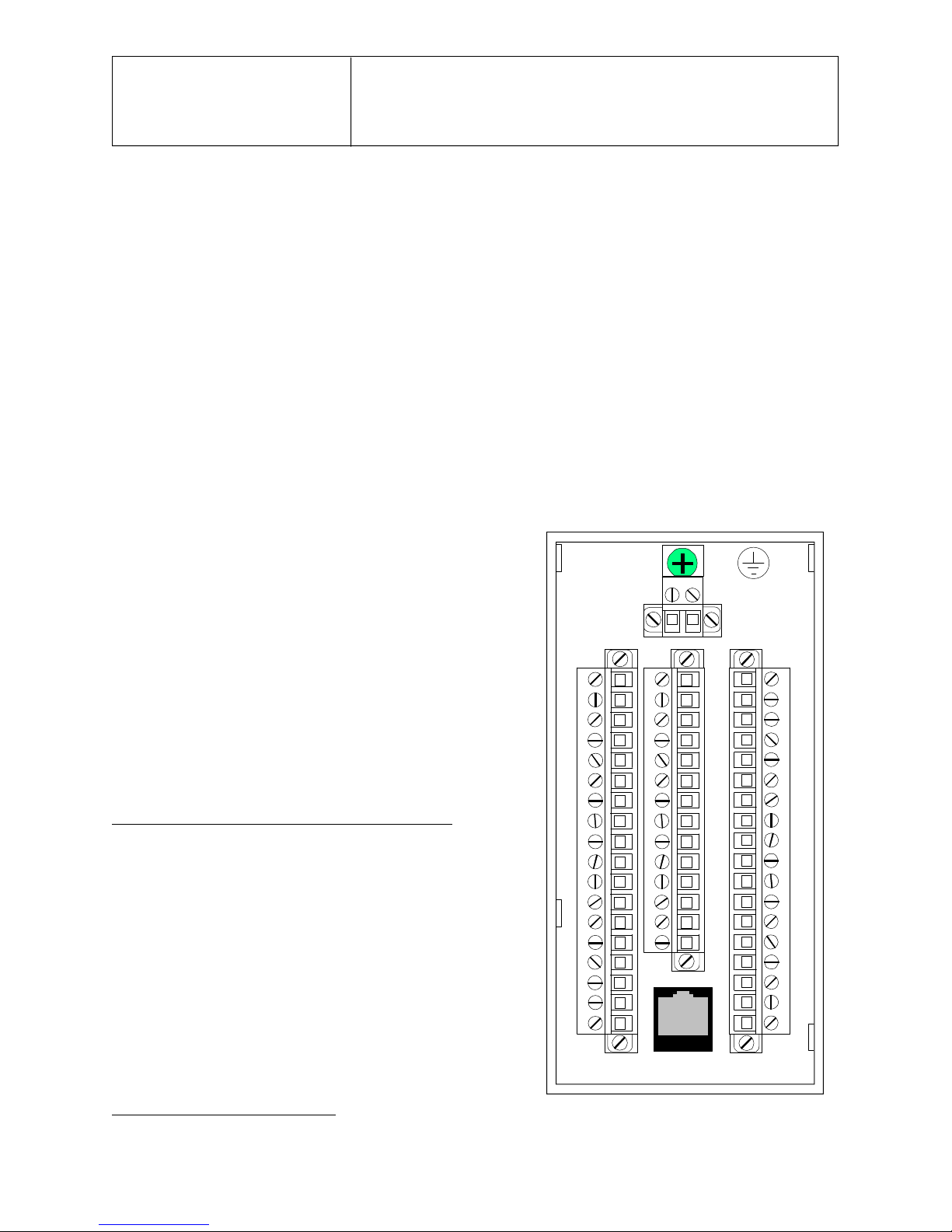
Direct entry connectors are shown in the adjacent figure.
There are four connectors with 52 screw-clamping terminal
connections. Each connector consists of a case mounted
portion and a plug-in portion. The plug-in portion of each
connector is securely fastened to the case mounted portion
by a screw at each end of the plug-in. The plug-in portion
can be completely wired and then plugged into the case
mounted portion.
Terminal functions and numbers have not changed. For
example, Station/Transmitter Common is terminal 6 on the
side entry and direct entry connectors.
A standard 8-wire Ethernet connector is provided near the
bottom of the assembly. A case ground screw is provided
near the top of the assembly, as in the side entry connectors.
The next page contains an illustration that states the
connections to the direct entry connectors.
AG00325a
1
Side entry and direct entry refer to the entry of wires into terminals installed on a rear connector assembly.
Page 2
UMA353-1-6
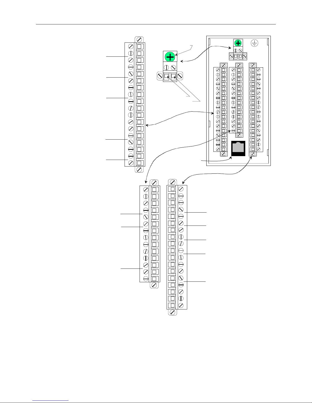
2
twinaxial cable shields are to be grounded.
Terminal Function, ID, and Number
Network Communications A, NCA, 3
Network Communications B, NCB, 4
Transmitter Power 26 Vdc+, XMTR+, 5
Transmitter/Station Common, COM, 6
Transmitter Power, 26 Vdc+, XMTR+, 7
Digital Output 1+, DOUT1+, 8
Digital Outputs 1/2 Common, DOUTC, 9
Digital Output 2+, DOUT2+, 10
Digital Input 1+, DIN1+, 11
Digital Input 1-, DIN-, 12
Digital Input 2+, DIN2+, 13
Digital Input 2-, DIN2-, 14
Digital Input 3+, DIN3+, 15
Digital Input 3-, DIN3-, 16
Analog Output 1+, AOUT1+, 17
Analog Output 1/2 Common, AOUTC, 18
Analog Output 2+, AOUT2+, 19
Analog Input 1+, AIN1+, 20
Case/Safety Ground
Power Input
AC Hot or DC+, H
AC Neutral or DC-, N
Ethernet
Connector
Terminal Function, ID, and Number
Analog Input 1/2 Common, AINC, 21
Analog Input 2+, AIN2+, 22
Analog Input 3+, AIN3+, 23
Analog Input 3 Common, AINC, 24
I/O Bus A, IOA, 25
I/O Bus B, IOB, 26
Relay Output 1 Normally Closed, ROUT1nc, 27
Relay Output 1 Common, ROUT1c, 28
Relay Output 1 Normally Open, ROUT1no, 29
Relay Output 2 Normally Closed, ROUT2nc, 30
Relay Output 2 Common, ROUT2c, 31
Relay Output 2 Normally Open, ROUT2no, 32
Analog Output 3+, AOUT3+, 33
Analog Output 3 Common, AOUTC, 34
AG00326a
Notes:
1. Terminal numbers are shown on each connector. The plug-in portions of the connectors are packed with a case.
The connectors are keyed.
2. Case/Safety Ground - Connect to green screw at top center of rear terminal area.
3. NCA and NCB - Connect LIL Twinaxial Cable or twisted pair wiring. Refer to Section 6.5 for additional details.
4. IOA and IOB - LonWorks bus connections. Twisted pair wiring is typical.
5. Ground Bus - An external, user-supplied ground bus can ease connection of multiple grounds, particularly when
Terminal Number, Function, and ID
35, Digital Input Universal 1+, DINU1+
36, Digital Input Universal 1-, DINU137, Digital Input Universal 2+, DINU2+
38, Digital Input Universal 2-, DINU2-
39, Transmitter Power 26 Vdc+, XMTR+
40, Transmitter/Station Common, COM
41, Analog Input 4+, AIN4+
42, Analog Input Common, AINC
43, Digital Input 4+, DIN4+
44, Digital Input 4-, DIN445, Analog Input Universal 1 a, AINU1a
46, Analog Input Universal 1 b, AINU1b
47, Analog Input Universal 1 c, AINU1c
48, Analog Input Universal 1 d, AINU1d
49, Analog Input Universal 2 a, AINU2a
50, Analog Input Universal 2 b, AINU2b
51, Analog Input Universal 2 c, AINU2c
52, Analog Input Universal 2 d, AINU2d
Rear Terminal Layout and Terminal Assignments
Page 3

UMA353-1-6
3
Wiring Guidelines
Wire Size - Each terminal can accept:
• one 12-24 AWG (2.5-0.2 mm2)
• two 16 AWG (1.3 mm2)
• three 18 AWG (0.96 mm2)
Wire stripping length - 1/4" (6 mm) typical, 9/32" (7 mm) maximum.
Terminal and ground screw torque:
• connector terminals - 4.4-5.3 in. lbs (0.5-0.6 N-m)
• green ground screw - 20 in. lbs (2.26 N-m)
Making Connections to the Direct Entry Terminals
The plug-in portions of the connectors are supplied in a kit that accompanies the case. Terminal functions
and numbers have not changed. For example, Station/Transmitter Common is terminal 6 on the side entry
and direct entry connectors.
WARNING
Hazardous voltage can cause death or serious injury.
Remove power from all wires and terminals before
working on this equipment.
For each terminal:
1. Refer to the body of the User’s Manual, particularly Section 6 Installation, for details concerning the
connections to the terminal to be wired.
2. Refer to the figure on the previous page and determine the location of the target terminal.
3. Loosen the captive screw adjacent to the target terminal.
4. Strip the end of a wire 1/4" (6 mm). Component leads should be insulated with sleeving leaving a
bare lead of 1/4" (6 mm).
5. Insert the wire or component lead into the square terminal opening.
6. Tighten the adjacent screw to 4.4-5.3 in. lbs (0.5-0.6 N-m) to clamp the wire or lead. Do not over
tighten.
7. When the connector is completely wired, plug it into the mating connector on the back of the case.
The connectors are keyed. Gently tighten the screw at each end of the connector. Do not over tighten.
8. The Ethernet connector accepts a standard 8-wire Ethernet cable. Insert the cable-mounted connector
until the locking tab engages.
9. When all wiring is complete, check each connection to be sure that the proper wire(s) or component is
connected and that the inserted leads are securely clamped.
Page 4

UMA353-1-6
4
10. Install the supplied cover as described in the illustration below. Use of larger gauge wires or wires
with very thick or very stiff insulation may prevent installation of the cover, or cause the cover to pop
off, unless the cable bundle is securely laced or tie wrapped.
To install or
remove cover:
squeeze
both sides
~1/16"
to clear
alignment
tabs.
AG00327a
To Install Terminal Cover:
1. Orient the cover as shown. Note the four hooked
tabs and Ethernet cable clearance cutout.
2. Squeeze the cover slightly at the two small cutouts
in the cover edges and fully insert the four hooked
cover tabs in the rear panel slots.
3. Allow cover sides to relax. Pull the cover straight
down until it snaps into place. The cutouts in the
cover edges will engage two alignment tabs on
the rear panel.
Where needed, the Ethernet cable should exit
through the large cutout in the cover.
To Remove Cover:
1. Squeeze the cover slightly at the two cutouts
in the cover edges (about 2" down from the
top of the cover) and push cover upward.
2. Pull cover out from rear panel.
Ethernet cable cutout.
Installing the Cover
Servicing Note
A Model 353 case with side entry connectors can be upgraded with direct entry connectors. Order the
Rear Terminal Upgrade Kit below.
Rear Terminal Upgrade Kit - PN16353-230
Includes:
Connector Socket Assembly
Connectors
Cover
n
Siemens Energy & Automation, Inc. assumes no liability for errors or omissions in this document or for the application and use
of information included in this document. The information herein is subject to change without notice.
Procedures in this document have been reviewed for compliance with applicable approval agency requirements and are
considered sound practice. Neither Siemens Energy & Automation, Inc. nor these agencies is responsible for repairs made by
the user.
 Loading...