

Page 1

Mitsubishi Industrial Robot
BFP-A8741-D
CR800-D series controller
CR750-D/CR751-D series controller
CRnD-700 series controller
PROFIBUS DP-V0 Slave Interface
Instruction Manual
2D-TZ577
Page 2

Page 3
Safety Precautions
Always read the following precautions and the separate "Safety
Manual" before starting use of the robot to learn the required
measures to be taken.
CAUTION All teaching work must be carried out by an operator who has received special
training.
(This also applies to maintenance work with the power source turned ON.)
→Enforcement of safety training
CAUTION For teaching work, prepare a work plan related to the methods and procedures
of operating the robot, and to the measures to be taken when an error occurs
or when restarting. Carry out work following this plan.
(This also applies to maintenance work with the power source turned ON.)
→Preparation of work plan
WARNING Prepare a device that allows operation to be stopped immediately during
teaching work.
(This also applies to maintenance work with the power source turned ON.)
→Setting of emergency stop switch
CAUTION During teaching work, place a sign indicating that teaching work is in progress
on the start switch, etc.
(This also applies to maintenance work with the power source turned ON.)
→Indication of teaching work in progress
DANGER Provide a fence or enclosure during operation to prevent contact of the operator
and robot.
→Installation of safety fence
CAUTION Establish a set signaling method to the related operators for starting work,
and follow this method.
→Signaling of operation start
CAUTION As a principle turn the power OFF during maintenance work. Place a sign
indicating that maintenance work is in progress on the start switch, etc.
→Indication of maintenance work in progress
CAUTION Before starting work, inspect the robot, emergency stop switch and other
related devices, etc., and confirm that there are no errors.
→Inspection before starting work
Page 4
The points of the precautions given in the separate "Safety Manual" are given below.
Refer to the actual "Safety Manual" for details.
DANGER When automatic operation of the robot is performed using multiple control
devices (GOT, programmable controller, push-button switch), the interlocking
of operation rights of the devices, etc. must be designed by the customer.
CAUTION Use the robot within the environment given in the specifications. Failure to do
so could lead to faults or a drop of reliability.
(Temperature, humidity, atmosphere, noise environment, etc.)
CAUTION Transport the robot with the designated transportation posture. Transporting
the robot in a non-designated posture could lead to personal injuries or faults
from dropping.
CAUTION Always use the robot installed on a secure table. Use in an instable posture
could lead to positional deviation and vibration.
CAUTION Wire the cable as far away from noise sources as possible. If placed near a
noise source, positional deviation or malfunction could occur.
CAUTION Do not apply excessive force on the connector or excessively bend the cable.
Failure to observe this could lead to contact defects or wire breakage.
CAUTION Make sure that the workpiece weight, including the hand, does not exceed the
rated load or tolerable torque. Exceeding these values could lead to alarms or
faults.
WARNING Securely install the hand and tool, and securely grasp the workpiece. Failure to
observe this could lead to personal injuries or damage if the object comes off or
flies off during operation.
WARNING Securely ground the robot and controller. Failure to observe this could lead to
malfunctioning by noise or to electric shock accidents.
CAUTION Indicate the operation state during robot operation. Failure to indicate the state
could lead to operators approaching the robot or to incorrect operation.
WARNING When carrying out teaching work in the robot's movement range, always secure
the priority right for the robot control. Failure to observe this could lead to
personal injuries or damage if the robot is started with external commands.
CAUTION Keep the jog speed as low as possible, and always watch the robot. Failure to do
so could lead to interference with the workpiece or peripheral devices.
Page 5
CAUTION After editing the program, always confirm the operation with step operation before
starting automatic operation. Failure to do so could lead to interference with
peripheral devices because of programming mistakes, etc.
CAUTION Make sure that if the safety fence entrance door is opened during automatic
operation, the door is locked or that the robot will automatically stop. Failure to do
so could lead to personal injuries.
CAUTION Never carry out modifications based on personal judgments, non-designated
maintenance parts. Failure to observe this could lead to faults or failures.
WARNING When the robot arm has to be moved by hand from an external area, do not place
hands or fingers in the openings. Failure to observe this could lead to hands or
fingers catching depending on the posture.
CAUTION Do not stop the robot or apply emergency stop by turning the robot controller's
main power OFF. If the robot controller main power is turned OFF during automatic
operation, the robot accuracy could be adversely affected. Also a dropped or
coasted robot arm could collide with peripheral devices.
CAUTION Do not turn OFF the robot controller's main power while rewriting the robot
controller's internal information, such as a program and parameter. Turning OFF
the robot controller's main power during automatic operation or program/parameter
writing could break the internal information of the robot controller.
DANGER Do not connect the Handy GOT when using the GOT direct connection function of
this product. Failure to observe this may result in property damage or bodily injury
because the Handy GOT can automatically operate the robot regardless of whether
the operation rights are enabled or not.
DANGER Do not connect the Handy GOT to a programmable controller when using an iQ
Platform compatible product with the CR750-Q/CR751-Q/CR800-R/CR800-Q controller.
Failure to observe this may result in property damage or bodily injury because the
Handy GOT can automatically operate the robot regardless of whether the operation
rights are enabled or not.
DANGER Do not remove the SSCNET III cable while power is supplied to the multiple CPU
system or the servo amplifier. Do not look directly at light emitted from the tip of
SSCNET III connectors or SSCNET III cables of the Motion CPU or the servo
amplifier. Eye discomfort may be felt if exposed to the light.
(Reference: SSCNET III employs a Class 1 or equivalent light source as
specified in JIS C 6802 and IEC60825-1 (domestic standards in Japan).)
DANGER Do not remove the SSCNET III cable while power is supplied to the controller.
Do not look directly at light emitted from the tip of SSCNET III connectors or
SSCNET III cables. Eye discomfort may be felt if exposed to the light.
(Reference: SSCNET III employs a Class 1 or equivalent light source as
specified in JIS C 6802 and IEC60825-1 (domestic standards in Japan).)
Page 6
DANGER Attach the cap to the SSCNET III connector after disconnecting the SSCNET III cable.
If the cap is not attached, dirt or dust may adhere to the connector pins, resulting in
deterioration connector properties, and leading to malfunction.
CAUTION Make sure there are no mistakes in the wiring. Connecting differently to the way
specified in the manual can result in errors, such as the emergency stop not
being released. In order to prevent errors occurring, please be sure to check
that all functions (such as the teaching box emergency stop, customer
emergency stop, and door switch) are working properly after the wiring setup
is completed.
CAUTION Use the network equipments (personal computer, USB hub, LAN hub, etc)
confirmed by manufacturer. The thing unsuitable for the FA environment
(related with conformity, temperature or noise) exists in the equipments connected
to USB. When using network equipment, measures against the noise, such as
measures against EMI and the addition of the ferrite core, may be necessary.
Please fully confirm the operation by customer. Guarantee and maintenance
of the equipment on the market (usual office automation equipment) cannot
be performed.
CAUTION To maintain the safety of the robot system against unauthorized access from external
devices via the network, take appropriate measures. To maintain the safety against
unauthorized access via the Internet, take measures such as installing a firewall.
Page 7

Revision History
Printing date
Manual No.
Description
2008-03-25
BFP-A8741
Initial edition
2008-04-15
BFP-A8741-A
Error in writing correction.
Hyper link was corrected.
2016-08-08 BFP-A8741-B
・
・The back cover was corrected.
・
・The cover and corporate logo mark of this manual was changed.
2017-05-31 BFP-A8741-C
2018-02-01 BFP-A8741-D
・The CR800-D series controller was added.
・Safety Precautions was revised. (The CR800-Q controller was added.)
Page 8
Introduction
Indicates an immediately hazardous situation which, if not properly dealt
Indicates a hazardous situation which, if not properly dealt with, could result
Indicates a hazardous situation which, if not properly dealt with, could result
This manual or any part thereof may not be reproduced in any form or by any form without permission.
Thank you for purchasing Mitsubishi Electric Industrial Robot.
The PROFIBUS DP-V0 Slave Interface (2D-TZ577) is an optional device which, installed into the
CRnD-700 series, CR750-D/CR751-D series, or CR800-D series Robot Controller, permits you to connect
the Robot Controller to a PROFIBUS DP-V0 network.
Before using the Interface, read this manual and familiarize yourself with all pages to ensure safe operation
and obtain maximum satisfactory service from the PROFIBUS DP-V0 Slave Interface (2D-TZ577).
Note: All descriptions in this manual assume that the user has an adequate understanding about basic
operating procedures and functions which pertain to the Mitsubishi Industrial Robot. For detailed
information about the basic operating procedures, refer to the "Instruction Manual - Detailed Description of
Functions and Operation" which is separately issued.
Safety notation used in this manual:
DANGER
WARNING
CAUTION
·
· All the contents of this manual are subject to change without notice.
· Specification values appearing in this manual are based on the tests conducted in accordance with
Mitsubishi Electric's standard procedures.
· Mitsubishi Electric prepared this manual with close attention to every detail. However, in case that you
find any point in this manual which is not quite clear or any information which is not correctly presented
or missing, your local sales representative or Mitsubishi MELFA Telephone Customer Service Center
should be contacted for advice.
· Trade names or trademarks appearing in this manual are the property of their respective owners.
· The notations "®" and "TM" are omitted in this manual.
Copyright(C) 2009-2018 MITSUBISHI ELECTRIC CORPORATION ALL RIGHTS RESERVED
with, will result in death or serious injury.
in death or serious injury.
in injury, or property damage alone.
Page 9

[Table of Contents]
1. Before Using PROFIBUS DP-V0 Slave Interface .......................................................................................... 1
1.1 About Terms Used in This Manual .......................................................................................................... 1
1.2 How to Use This Manual ......................................................................................................................... 2
2. Workflow ......................................................................................................................................................... 3
2.1 Work Procedure ...................................................................................................................................... 3
3. Features and Specification of 2D-TZ577 Card ............................................................................................... 4
3.1 What is PROFIBUS DP ........................................................................................................................... 4
3.2 Features of 2D-TZ577 Card .................................................................................................................... 5
3.3 Specification of 2D-TZ577 Card .............................................................................................................. 7
3.3.1 General Specification ....................................................................................................................... 7
3.3.2 Transmission Specification .............................................................................................................. 8
3.3.3 Network Configuration ..................................................................................................................... 8
3.3.4 Accommodated Versions ................................................................................................................. 9
3.4 Robot Parameters ................................................................................................................................. 10
3.5 Robot Controller Input/Output Signals .................................................................................................. 12
3.6 About Dedicated Input/Output ............................................................................................................... 13
3.7 Specification Relative to Robot Language ............................................................................................ 13
3.7.1 Robot System State Variables Relative to 2D-TZ577 Card ........................................................... 13
3.8 About Output Signal Reset Patterns ..................................................................................................... 16
3.9 Hardware of 2D-TZ577 Card ................................................................................................................. 17
3.9.1 Overall View ................................................................................................................................... 17
3.9.2 LED ................................................................................................................................................ 17
4. Out of the Package ....................................................................................................................................... 18
4.1 Checking Component Parts .................................................................................................................. 18
4.2 Items To Be Furnished by User ............................................................................................................. 18
5. Hardware Setup............................................................................................................................................ 20
5.1 Hardware Setup for 2D-TZ577 Card ..................................................................................................... 20
6. Connection and Wiring ................................................................................................................................. 21
6.1 Installing A 2D-TZ577 Card into Robot Controller ................................................................................. 21
6.1.1 CR1D Robot Controller .................................................................................................................. 21
6.1.2 CR2D Robot Controller .................................................................................................................. 22
6.1.3 CR3D Robot Controller .................................................................................................................. 23
6.1.4 CR750-D/CR751-D Robot Controller ............................................................................................. 24
6.1.5 CR800-D Robot Controller ............................................................................................................. 25
6.2 Connector Pin Configuration (D-SUB9 Pin) .......................................................................................... 26
6.3 Wiring .................................................................................................................................................... 26
6.4 About Noise Control .............................................................................................................................. 27
Page 10

6.4.1 CR1D Controller ............................................................................................................................. 27
6.4.2 CR2D Controller ............................................................................................................................. 27
6.4.3 CR3D Controller ............................................................................................................................. 28
6.5 Checking Connections .......................................................................................................................... 29
7. Procedure before Startup ............................................................................................................................. 30
7.1 Procedure for Running Self-diagnosis .................................................................................................. 31
7.2 Parameter Settings on the Side of Master Station ................................................................................ 31
7.2.1 Procedure for Establishing Parameters ......................................................................................... 31
7.2.2 Slave Parameters ........................................................................................................................... 32
7.3 Parameter Settings on the Side of Robot Controller ............................................................................. 35
7.4 Have A Try For It .................................................................................................................................... 37
7.4.1 Setting Dedicated Input/Output ...................................................................................................... 37
7.4.2 About General-purpose Input/Output ............................................................................................. 37
7.4.3 Examples of Robot Program (Using General-purpose I/O) ........................................................... 38
7.4.4 A Sample Program for Checking Input/Output ............................................................................... 39
8. Troubleshooting ............................................................................................................................................ 40
8.1 A Listing of Errors .................................................................................................................................. 40
8.2 At the Occurrence of Error 8570 (PROFIBUS Communication Timeout) ............................................. 42
9. Appendix ....................................................................................................................................................... 43
9.1 Displaying Option Card Information ...................................................................................................... 43
Page 11

1 Before Using PROFIBUS DP-V0 Slave Interface
Term
Description
PROFIBUS DP-V0
A basic version of PROFIBUS DP which permits the execution of the following
Others
PROFIBUS DP-V1
A version of PROFIBUS DP which permits the execution of the following functions
Others
PROFIBUS DP-V2
A version of PROFIBUS DP which permits the execution of the following functions
Others
2D-TZ577
PROFIBUS DP-V0 Slave Interface (a complete set of products)
2D-TZ577 Card
PROFIBUS DP-V0 Slave Interface Card (TZ577)
Master Station
A station residing in the equipment (typically, PLS or personal computer) which
Class 2.
Class 1 Master Station
Equipment which exchanges input/output data with Slave Stations.
Class 2 Master Station
Equipment which verifies station number settings and operating statuses through
diagnosis.
Slave Station
A lo wer-level station which communicates with Master Station.
Repeater
A device which provides a link between the segments of a PROFIBUS DP network.
Terminator resistor
Resistor connected to the individual segments of a PROFIBUS DP network at each
network are enabled to fulfill intended purposes.
Slave parameter
Slave station parameter established by Master Station. Items of parameter
information are stated on a GSD file.
Station number
A number assigned to Master Station or Slave Station. Numbering is in the range of
0 to 125.
I/O configuration
information (data module)
Information about input/output configuration at Slave Station.
Input data
Data which is sent by 2D-TZ577 Card and received by Master Station.
(Data inputted by Master Station)
Output data
Data which is sent by Master Station and received by 2D-TZ577 Card.
(Data outputted by Master Station)
Global control
A function which allows Class 1 Master Station to send an input/output data
synchronization command to Slave Stations.
Communication WDT
A watchdog timer established in the slave parameter at Master Station.
GSD file
An electronic file stating parameter settings at Slave Station. A data setting
settings.
1. Before Using PROFIBUS DP-V0 Slave Interface
This chapter explains checks or precautions that you should perform or take before using the PROFIBUS DP-V0
Slave Interface (2D-TZ577).
1.1 About Terms Used in This Manual
Table 1-1 Terms Used in This Manual
functions:
· Input/output data communications
·
in additions to those available from PROFIBUS DP-V0:
· A cyclic communications (asynchronous data communications)
· Alarm notification
·
in additions to those available from PROFIBUS DP-V1:
· Time stamping
·
controls a data link system. There must be at least one Master Station in any
system. As described below, Master Station comes in two varieties: Class 1 and
communications with Slave Stations. It serves as a network administration master
station and takes care of such tasks as startup, maintenance service, and
end. Actually, terminator resistors built in the connector used with a PROFIBUS
software compliant with Master Station, which is used to establish slave parameter
About Terms Used in This Manual 1- 1
Page 12

1 Before Using PROFIBUS DP-V0 Slave Interface
Section
Title
Contents
This section describes how to use this document (PROFIBUS DV-V0
the information contained before attempting to use the 2D-TZ577 Card.
This section describes the work necessary to build a PROFIBUS DP
system. Carry out each work step exactly as indicated.
Features and Specification of
2D-TZ577 Card
This chapter describes the features and specification of the 2D-TZ577
Card.
Upon receipt of the 2D-TZ577 Card, check to see that all items are in the
package and that the version of the Robot Controller is as specified.
5
Hardware Setup
Hardware setup need not be done in regard to the product in question.
This section describes the method used to connect the 2D-TZ577 Card to
the Master Station via cables.
This section describes steps you have to take before placing PROFIBUS
DP system into operation.
This section presents information that helps find solutions when
2D-TZ577 Card. Make reference to this section as occasion arises.
The appendix explains the method for displaying information about the
2D-TZ577 Card by means of RT ToolBox2/RT ToolBox3.
1.2 How to Use This Manual
This manual discusses the functions of the 2D-TZ577 Card with its constituent sections organized as shown in
the table below. For information about the functions available from the standard Robot Controller and the
operating method thereof, refer to the "Instruction Manual" that is supplied with the Controller.
Table 1-2 Organization of This Instruction Manual
Before Using PROFIBUS
1
DP-V0 Slave Interface
2 Workflow
3
4 Out of the Package
6 Connection and Wiring
Slave Interface Instruction Manual). Read and familiarize yourself with
7 Procedure before Startup
8 Troubleshooting
9 Appendix
operational anomalies or errors are encountered during the use of the
How to Use This Manual 1- 2
Page 13
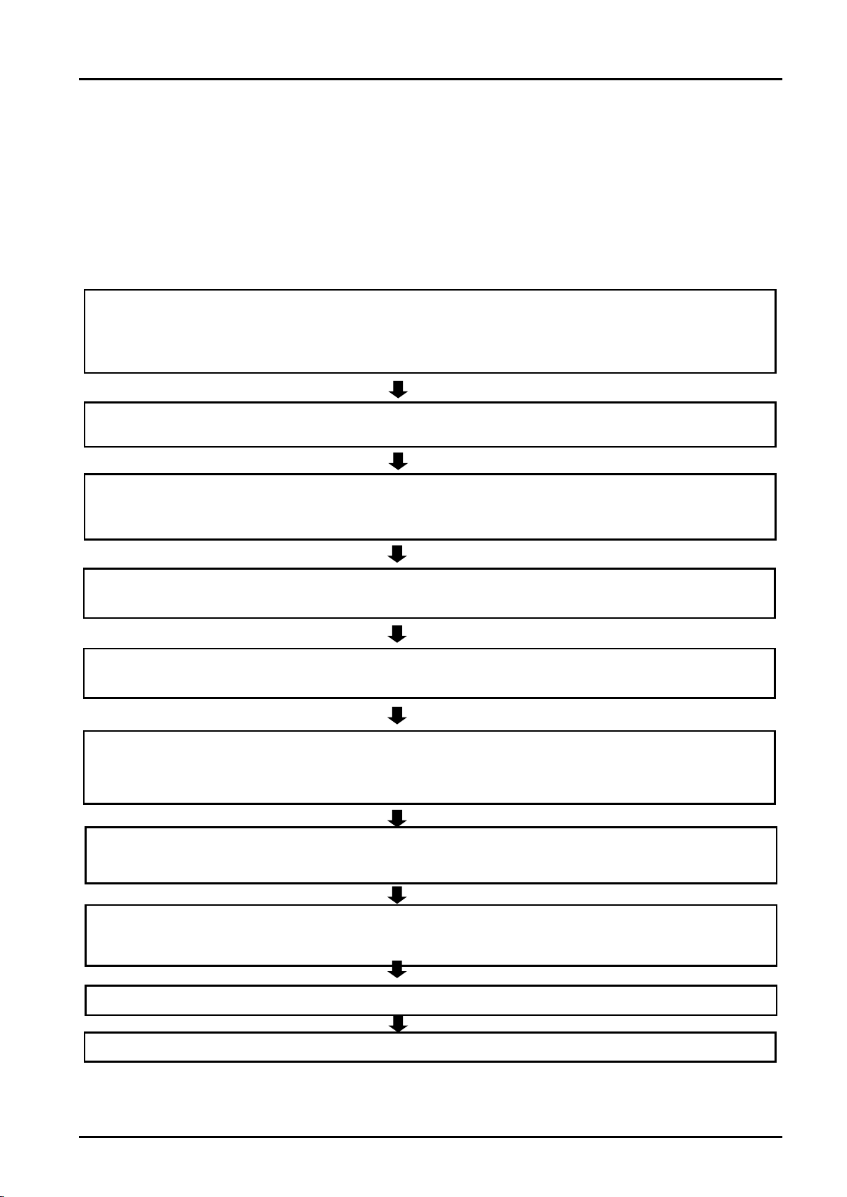
2 Workflow
1 Deciding a specification for PROFIBUS DP network
・・・・・・・・・・
See Section 3.
Make a decision on interface details in regard to system signals utilizing PROFIBUS DP after gaining an
understanding of PR
OFIBUS DP specification.
(Such details include alignment of dedicated input/output signals and arrangement pertaining to general
-purpose
input/output signals.)
2. Unpacking component parts
・・・・・・・・・・・・・・・・・・・・・・・・・・・・・・・
See Section 4.
Unpack cartons containing your purchase and ensure that all the necessary items are ready for installation.
3. Hardware setup and installation to robot controller
・・・・・・・・・・・・
See Section 5 and Section 6.1.
The 2D-TZ577 Card lets you do without hardware setup. Install the Card into the Robot Controller, as it is.
5.
Establishing parameters for Master Station
・・・・・・・・・・・・・・・・・・
See Section 7.2.
Make signal alignment and Slave Station number settings at the Master Station.
6. Establishing parameters for Robot Controller
・・・・・・・・・・・・・・・・・
See Section 7.3.
Make Robot Controller-side station number settings.
Choose a setting to indicate whether the Robot Controller should
run a self-diagnosis at power-on.
Carry out signal alignment for dedicated I/O.
7. Making the connection
・・・・・・・・・・・・・・・・・・・・・・・・・・・・・・・・・・・
See Sections 6.2 through 6.5.
Connect the 2D-TZ577 Card installed in the Robot Controller to the Master Station, using the PROFIBUS-specific
cable and connector.
8. Creating a robot program
・・・・・・・・・・・・・・・・・・・・・・・・・・・・・・・・・
See Section 7.4.
Create a robot program compliant with the specification decided in Step 1 above and activate the robot in auto
operation mode.
9. Actions at the occurrence of a trouble
・・・・・・・
・・・・・・・・・
・・・・・・・
See Chapter 8.
4. Performing self-diagnosis
・・・・・・・・・・・・・・・・・・・・・・・・・・・・・・・・・
See Section 7.1.
Run a self
-diagnosis and ensure that the 2D
-TZ577 Card has no problems with its hardware.
10. Work complete
2. Workflow
Workflow you should follow to construct a PROFIBUS DP network system is shown below. Carry out each work
step exactly as indicated.
2.1 Work Procedure
Work Procedure 2- 3
Page 14
3 Features and Specification of 2D-TZ577 Card
Robot Controller
CR75n-D
Series
Robot Controller
CR800-D
Series
PROFIBUS DP-VO Slave
Connector with
MELSEC sequencer, etc.
Connector with built
terminator resistors
(to be furnished by the
user)
Equipment from other
Robot Controller
CRnD-700
Series
Master Station unit
Slave Station unit
Personal
computer
QXxxxx
QJ71E71-100QJ71E71-100QJ71E71-100QJ71E71-100
RUN
INIT.
OPEN
SD
RUN
INIT.
OPEN
SD
RUN
INIT.
OPEN
SD
RUN
INIT.
OPEN
SD
ERR.
COM.ERR.
100MRD
ERR.
COM.ERR.
100MRD
ERR.
COM.ERR.
100MRD
ERR.
COM.ERR.
100MRD
QXxxxx
QXxxxx
PULL
MITSUBISHI
MEL S EC
POWER
MP
G
R
I
O
FRONT
M
PG
R
IO
B
AT
BA
T
AC
FA
I
LA
CF
A
IL
FRONT
Q173NCCPU
QJ71E71-100
RUN
INIT.
OPEN
SD
ERR.
COM.ERR.
100MRD
QJ71E71-100
RUN
INIT.
OPEN
SD
ERR.
COM.ERR.
100MRD
QXxxxx
QJ71E71-100QJ71E71-100QJ71E71-100QJ71E71-100
RUN
INIT.
OPEN
SD
RUN
INIT.
OPEN
SD
RUN
INIT.
OPEN
SD
RUN
INIT.
OPEN
SD
ERR.
COM.ERR.
100MRD
ERR.
COM.ERR.
100MRD
ERR.
COM.ERR.
100MRD
ERR.
COM.ERR.
100MRD
QXxxxx
Q
Xxxxx
PULL
MITSUBISHI
MEL S EC
POWER
MPG
RIO
FRONT
MPG
RIO
BATBAT
ACFAILACFAIL
FRONT
Q173NCCPU
Q
J
71
E7
1
-1
0
0
R
UN
INIT.
O
PE
N
S
D
E
RR
.
COM.ERR.
1
00
MR
D
Q
J7
1E
7
1-
1
00
R
UN
INIT.
O
PE
N
S
D
E
RR
.
COM.ERR.
1
00
MR
D
Varied
devices
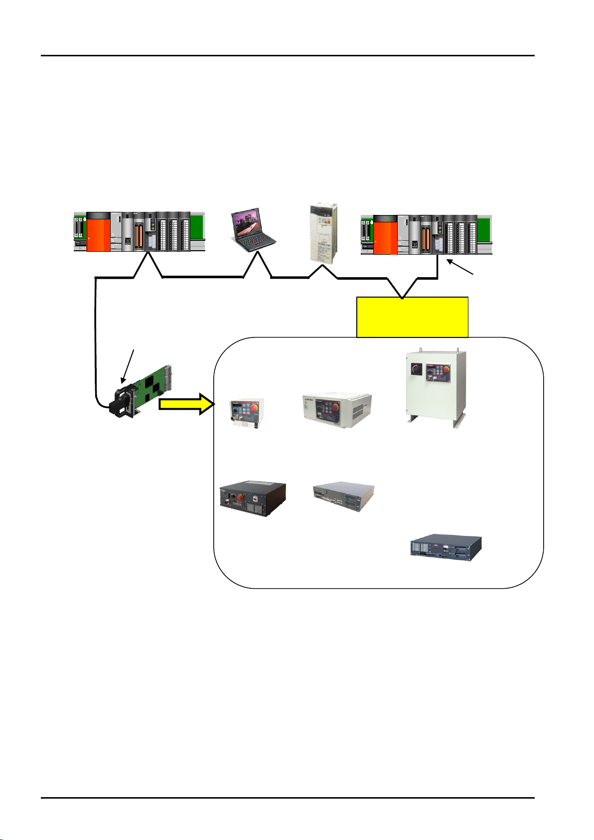
3. Features and Specification of 2D-TZ577 Card
3.1 What is PROFIBUS DP
PROFIBUS-compliant
Interface Card (2D-TZ577)
Only one card can be
installed into an option slot
on the Controller*1.
-in
(to be furnished by the user)
CR1D
CR750-D CR751-D
CR2D
manufacturer or
Mitsubishi associate
CR3D
CR800-D
built-in
terminator
resistors
(to be furnished
by the user)
PROFIBUS is one of the recognized fieldbus standards. PROFIBUS comes in three variations: general-purpose
PROFIBUS FMS, PROFIBUS DP for factory automation application, and PROFIBUS PA for process automation
application.
The 2D-TZ577 Card is intended to serve as a slave station which supports PROFIBUS DP-V0 capabilities.
It does not support PRORIBUS DP-V1 or PROFIBUS DP-V2 which is an extension of PROFIBUS DP-V0.
What is PROFIBUS DP 3- 4
Figure 3-1 An Example of PROFIBUS Network Configuration
Page 15

3 Features and Specification of 2D-TZ577 Card
192 words in combined total
(*1) Number of the option slots varies with the Controller you use.
CR1D: Provided only with Slot 1.
CR2/3D: Provided with Slots 1 thru 3 (only one of the three slots used to install the Card at any one time)
Details about PROFIBUS
To learn more about PROFIBUS, visit a Japan PROFIBUS Association website at http://www.profibus.com/
3.2 Features of 2D-TZ577 Card
The 2D-TZ577 Card has the following features:
(1) Compliance with EN 50170 Vo lume 2 (Part 1, 2, 3, 4, and 8)
Designed to provide compliance with EN 50170 Volume 2 (Part 1, 2, 3, 4, and 8), the 2D-TZ577 Card
serves only as a slave station in a PROFIBUS DP-V0 network.
(2) PROFIBUS DP-V0 Slave Interface Card for D-Type Robot Controller
The 2D-TZ577 Card is an optional card for use with the stand-alone type (D type) Robot Controller, not
usable for iQ Platform compatible type (Q type or R type). To connect iQ Platform compatible type (Q type
or R type) Robot Controller to a PROFIBUS DP network, use a MELSEC-Q Series PROFIBUS DP unit.
To connect R type Robot Controller to a PROFIBUS DP network, use a MELSEC iQ-R Series PROFIBUS
DP unit.
(3) Input/output data communications with Class 1 Master Station
The 2D-TZ577 Card is capable of conducting input/output data communications with PROFIBUS-DP Class
1 Master Station (Master Station which communicates with Slave Stations on a cyclic basis). This card is
intended to serve as a slave station which supports PROFIBUS DP-V0 capabilities. It does not
support PRORIBUS DP-V1 or PROFIBUS DP-V2 which is an extension of PROFIBUS DP-V0.
(a) Communicatable number of pieces of data
A single 2D-TZ577 Card allows communications in the following number:
Input data - 122 words maximum
Output data - 122 words maximum
(4) Communications with Class 2 Mater Station
The 2D-TZ577 Card is capable of conducting communications, as detailed below, with Class 2 Master
Station (Master Station for network administration which takes care of startup, maintenance and diagnosis
services).
• Reading from input send area/output receive area
• Reading I/O configuration information
• Changing station numbers
For instructions on using the each of the listed functions, see instruction manual which is supplied with
Class 2 Master Station being installed.
Features of 2D-TZ577 Card 3- 5
Page 16

3 Features and Specification of 2D-TZ577 Card
(5) Input/output data swapping
The 2D-TZ577 Card permits upper/lower bytes to be swapped at the time when input/output data is sent to
or received from Master Station. In a PROFIBUS DP network, the way the upper/lower bytes of input/output
data is treated differs depending on the type of Master Station, but there is no need for making input/output
data swapping at a program level.
(6) Global control
The 2D-TZ577 Card supports global control capability, enabling Class 1 Master Station to control
input/output data updating on the 2D-TZ577 Card by commands it transmits (SYNC, UNSYNC, FREEZE,
and UNFREEZE). For instructions on using the global control capability, see instruction manual which is
supplied with Class 1 Master Station being installed.
Features of 2D-TZ577 Card 3- 6
Page 17

3 Features and Specification of 2D-TZ577 Card
Item
Specification
Remark
Type name
TZ577
PROFIBUS specification complied
with
EN50170 Volume2(Part1,2,3,4,8)
PROFIBUS DP version supported
DP-V0 only
DP-V1 and DP-V2 not supported
Transmission rate
9.6k/19.2k/45.45k/93.75k/187.5k/5
00k/1.5M/3M/6M/12Mbaud
Set by parameters specified on
Master Station
Station number
0 to 125
Set by parameters specified on
Robot (default setting: 126*1)
Maximum communicatable number
192 words as the combined number
or output data)
Option slot that accepts an
Slot 1/Slop 2/Slot 3
Only one slot is used at any one
and 2 only.)
Number of cards installed
One
Installation of more than one card is
not permitted.
Concurrent use of 2D-TZ577 Card
and other fieldbus option card*2
Not permitted
Robot controller input/output
2000 to 3951
For details about signal alignment,
PROFIBUS Signals."
Terminator resistor
Uninstalled
If the 2D-TZ577 Card is used as a
Be Furnished by User."
Input/output signal access
2D-TZ577 Card send/receive data
signals like parallel I/O signals are.
3.3 Specification of 2D-TZ577 Card
The following table shows the specification of the 2D-TZ577 Card.
3.3.1 General Specification
Table 3-1 General Specification (2D-TZ577 Card)
of pieces of data
interface card
number
of pieces of input/output data (122
words as the total of pieces of input
is assigned to input/output signal
No. 2000 and up. In a
MELFA-BASIC V network, these
signals are treated as input/output
time
(CR1D is provided with Slot 1
only.)
(CR750-D, CR751-D, and
CR800-D are provided with Slot 1
see " Table 3-6 A Listing of
terminal station, terminator resistor
on a dedicated connector should be
enabled. For information about the
connector, see "
Table 4-2 Items To
(*1) Station number 126 causes the interface to be isolated from the PROFIBUS network.
Specify station numbers in the range of 0 to 125 for the purpose of input/output date communications.
(*2) CC-Link Interface Card and Device Net Interface Card (both under development).
Specification of 2D-TZ577 Card 3- 7
Page 18

3 Features and Specification of 2D-TZ577 Card
Item
Specification
Transmission specification
Electrical standard and characteristic
Compliant with EIA-RS485
Medium
Shielded twisted-pair cable (Type A)*1
Network configuration
Bus type (tree type when repeater(s) is (are) used)
Communication method
Polling
Transmission encoding method
NRZ
Maximum transmission range
used [m/network]
9.6kbps
19.2kbps
45.45kbps
93.75kbps
187.5kbps
1000
4000
500kbps
400
1600
1.5Mbps
200
800
3Mbps
6Mbps
12Mbps
Maximum number of intervening repeaters
3*2
Maximum number of units connected
(per segment)
Number of nodes connected/segment
32
3.3.2 Transmission Specification
Table 3-2 Transmission Specification
Transmission rate
Transmission range
[m/segment]
1200 4800
Transmission rate/maximum transmission
*2
range
32 (including repeater(s))
(*1) Specified in EN 50170 standard
(*2) Maximum transmission distance achievable by the use of repeaters:
Maximum transmission distance [m/network] = (number of repeaters + 1) x transmission distance
[m/segment]
3.3.3 Network Configuration
with three repeaters being
100 400
When creating a PROFIBUS DP network, note that the network comes in under the following design limits:
(1) Number of units that can be connected to the entire network (when repeaters are used)
Master + Slave ≤ 126
(2) Number of units which can be connected to a segment
Master + Slave + repeater
*1
≤ 32
(3) Maximum number of intervening repeaters
Up to 3 repeaters are allowed to intervene in the communication path between Master Station and
2D-TZ577 Card
(4) It is necessary to enable terminator resistors on a dedicated connector installed at the terminal station of
each segment.
(5) Maximum number of Slave Stations which can be connected to a Master Station depends on the
specification of the Master Station.
(*1) Repeater is counted in the number of units at each of the segments.
Specification of 2D-TZ577 Card 3- 8
Page 19

Segment
Mater Station
Repeater
…………….
…………….
Slave Station
No. 1
Slave Station
No. 2
Slave Station
No. 030
Slave Station
No. 031
Slave Station
No. 032
Slave Station
No. 060
Figure 3-2 An Example of Basic PROFIBUS DP Network Configuration
Name
Version
Robot Controller
P6k or later
Personal computer support
RT Tool Box 2: Ver.1.0.1 or later
Robot Controller.
3.3.4 Accommodated Versions
3 Features and Specification of 2D-TZ577 Card
software
Table 3-3 Accommodated Versions
* Ver. 1.3 or later is provided with a dialog box which can be used for making
PROFIBUS-related settings.
Even versions preceding 1.3 offer parameter a parameter setting screen that
permits you to make PROFIBUS-related settings.
For more information, see Section7.3
Parameter Settings on the Side of
Specification of 2D-TZ577 Card 3- 9
Page 20

3 Features and Specification of 2D-TZ577 Card
Parameter
name
STOP2
-1, -1
-1 /2000 to 3951
A parameter that specifies a dedicated input signal number to
uses "STOP2" to define an external stop signal.)
ORST2000
ORST3920
00000000,
00000000
0/1/*
A parameter that specifies value of output send data on the
Using PROFIBUS DP-V0 Slave Interface.)
PBMODE
0
0/2
A parameter that switches the operating mode of the 2D-TZ577
normal operation.
PBMC
1
1/2
A parameter that designates Master Station as Class 1 or Class
being used)
PBNUM
126
-1 to 125
A parameter that specifies station number for the 2D-TZ577
= -1."
E8500
0
0/1
A parameter that is used to temporarily reset an error state
power supply resetting is done.
3.4 Robot Parameters
Table 3-4 A Listing of Robot Parameters Used with PROFIBUS
Initial value Setting range Description
stop robot programs.
(Because the parameter "STOP" is fixed at "0", 2D-TZ577 Card
ORST2032
:
00000000,
00000000,
2D-TZ577 Card at the time of signal output reset.
(For details about related settings, see Section 3.8 Before
Card between "normal" and "self-diagnosis."
Normal mode = 0, self-diagnosis mode = 2
· When the self-diagnosis identifies an anomaly, an error
message is displayed.
("H.8504: PROFIBUS self-diagnosis shows occurrence of
an error.")
Return the operating mode to normal to continue with
·
2.
Class 1 Master Station is designated at factory default. To use
"Class 2," choose another parameter setting.
1: Class 1 Master (effected when the station number setting
parameter PBNUM shown below is used)
2: Class 2 Master (effected when changes of station numbers
are made from Class 2 Master Station - with PBNUM not
Card.
0 to 125: Station number setting value (Rewriting of station
number settings takes place within the flash ROM as well.)
-1: Station number clear (Station number settings within the
flash ROM are cleared.)
* After the station numbers are cleared, the value 126 is taken
on.
* If "No_Add_Chg" is specified with "true" when making
station number settings from Class 2 Master Station,
2D-TZ577 Card is disabled for change of station numbers.
To cancel this setting, clear station numbers with "PBNUM
when PROFIBUS-related error (indicated by a number in the
8500s) occurred.
(1: Resettable (But no communications are to be carried out.) /
0: Always error during the occurrence of an anomaly in the link)
* This parameter does not require power supply resetting
on the Robot Controller. The initial value of 0 will return if
Robot Parameters 3- 10
Page 21

3 Features and Specification of 2D-TZ577 Card
Parameter
name
PBCNT
40
0 to 65535
A parameter that specifies an interval at which the 2D-TZ577
TZ577 Card error being detected by the
Controller.
Initial value Setting range Description
Card is checked for error.
Unit interval: msec
In normal condition, use the 2D-TZ577 Card at its factory
default (40).
User may change the setting only when communication errors
are frequently encountered under the undue influence from
noise in his installation environment. Normally, a setting in the
range of 40 to 70msec will do. Increase the setting with great
care as this may result in the inability to generate an error
indication even when one occurs in the 2D-TZ577 Card.
With a value greater than "1" being specified (rounding-up
checked), the Controller generates an error indication only
when it has detected a 2D-TZ577 Card error continuously
during a specified period of time. The Controller does not
generate an error indication unless it has had continuous error
detection.
With "0" being specified, an error indication is generated
immediately upon a 2D-
Robot Parameters 3- 11
Page 22

3 Features and Specification of 2D-TZ577 Card
Input (received from Master Station)
Output (sent to Master Station)
Number
2000 to 3951
2000 to 3951
Number of
words
Usable number
of points
Number of
words
Usable number
of points
Number of
words
Usable number
of points
0 0 - to -
41
656
2000to2655
82
1312
2000to3311
1
16
2000to2015
42
672
2000to2671
83
1328
2000to3327
2
32
2000to2031
43
688
2000to2687
84
1344
2000to3343
3
48
2000to2047
44
704
2000to2703
85
1360
2000to3359
4
64
2000to2063
45
720
2000to2719
86
1376
2000to3375
5
80
2000to2079
46
736
2000to2735
87
1392
2000to3391
6
96
2000to2095
47
752
2000to2751
88
1408
2000to3407
7
112
2000to2111
48
768
2000to2767
89
1424
2000to3423
8
128
2000to2127
49
784
2000to2783
90
1440
2000to3439
9
144
2000to2143
50
800
2000to2799
91
1456
2000to3455
10
160
2000to2159
51
816
2000to2815
92
1472
2000to3471
11
176
2000to2175
52
832
2000to2831
93
1488
2000to3487
12
192
2000to2191
53
848
2000to2847
94
1504
2000to3503
13
208
2000to2207
54
864
2000to2863
95
1520
2000to3519
14
224
2000to2223
55
880
2000to2879
96
1536
2000to3535
15
240
2000to2239
56
896
2000to2895
97
1552
2000to3551
16
256
2000to2255
57
912
2000to2911
98
1568
2000to3567
17
272
2000to2271
58
928
2000to2927
99
1584
2000to3583
18
288
2000to2287
59
944
2000to2943
100
1600
2000to3599
19
304
2000to2303
60
960
2000to2959
101
1616
2000to3615
20
320
2000to2319
61
976
2000to2975
102
1632
2000to3631
21
336
2000to2335
62
992
2000to2991
103
1648
2000to3647
22
352
2000to2351
63
1008
2000to3007
104
1664
2000to3663
23
368
2000to2367
64
1024
2000to3023
105
1680
2000to3679
24
384
2000to2383
65
1040
2000to3039
106
1696
2000to3695
25
400
2000to2399
66
1056
2000to3055
107
1712
2000to3711
26
416
2000to2415
67
1072
2000to3071
108
1728
2000to3727
27
432
2000to2431
68
1088
2000to3087
109
1744
2000to3743
28
448
2000to2447
69
1104
2000to3103
110
1760
2000to3759
29
464
2000to2463
70
1120
2000to3119
111
1776
2000to3775
30
480
2000to2479
71
1136
2000to3135
112
1792
2000to3791
31
496
2000to2495
72
1152
2000to3151
113
1808
2000to3807
32
512
2000to2511
73
1168
2000to3167
114
1824
2000to3823
33
528
2000to2527
74
1184
2000to3183
115
1840
2000to3839
34
544
2000to2543
75
1200
2000to3199
116
1856
2000to3855
35
560
2000to2559
76
1216
2000to3215
117
1872
2000to3871
36
576
2000to2575
77
1232
2000to3231
118
1888
2000to3887
37
592
2000to2591
78
1248
2000to3247
119
1904
2000to3903
38
608
2000to2607
79
1264
2000to3263
120
1920
2000to3919
39
624
2000to2623
80
1280
2000to3279
121
1936
2000to3935
40
640
2000to2639
81
1296
2000to3295
122
1952
2000to3951
3.5 Robot Controller Input/Output Signals
Input/output signals processed in the Robot Controller are in the range of 2000 to 3951 maximum (equivalent to
192 words), respectively, irrespective of station numbers.
Table 3-5 PROFIBUS Input/Output Signal Numbers
The data sizes of input/output signal are specified by parameter settings on the side of the Master Station. The
combined number of pieces of input/output data is 192 words maximum while the respective number of pieces
of input/output data is 122 words maximum.
Examples: (Input - 122 words) + (output - 70 words) = 192 words in total
(Input - 96 words) + (output - 96 words) = 192 words in total
(Input - 10 words) + (output - 10 words) = 20 words in total
Table 3-6 A Listing of PROFIBUS Signals
Start End
Start End
Start End
Robot Controller Input/Output Signals 3- 12
Page 23

3 Features and Specification of 2D-TZ577 Card
Item
Type
Function
Read/write
M_In
Integer 1
Reads one bit of data from specified input signal.
Read
M_Out
Integer 1
Writes one bit of data into specified output signal.
Write
M_Inb
Integer 1
Reads 8 bits of data from specified input signal.
Read
M_Outb
Integer 1
Writes 8 bits of data into specified output signal.
Write
M_Inw
Integer 1
Read 16 bits of data from specified input signal.
Read
M_Outw
Integer 1
Write 16 bits of data into specified output signal.
Write
3.6 About Dedicated Input/Output
Signal numbers are assigned to 2D-TZ577 Cards. Assignment of these numbers to dedicated input/output
parameters permits them to be used as dedicated input/output. For more information about the dedicated
input/output, see Section 6 "Functions of External Input/Output" of the "Instruction Manual - Detailed Description
of Functions and Operation" which is separately issued.
3.7 Specification Relative to Robot Language
The follow subsection explains robot language (MELFA-BASIC V) which pertains to the 2D-TZ577 Card.
3.7.1 Robot System State Variables Relative to 2D-TZ577 Card
Table 3-7 A Listing of System State Variables Used for Data Input/Output
To avoid "Data separation" a read/write interlock as shown below need be provided in the application concerned
(robot program or PLC ladder).
An example of interlock being used where one-word data is sent from the Master Station to the robot is
illustrated in the form of a flowchart below.
About Dedicated Input/Output 3- 13
Page 24

3 Features and Specification of 2D-TZ577 Card
Meaning
Master Station*1
Robot
Data send/receive region
Data send region
Input: 2000 to 2015
PLC data write completed flag
WRTFLG
Input No. 2016
Robot data write completed flag
RDFLG
Output No. 2020
Start
End
Write one-word data
(data transmitted)
Write W RTFLG = 1
Input No. 2016 = 1?
Read Input Nos. 2000 to
2015 (data received)
Write Output No. 2020 = 1
RDFLG = 1?
Start
End
Master Robot
YES
NO
NO
YES
Write W RTFLG = 0
Input No. 2016 = 0?
Write Output No. 2020 = 0RDFLG = 0?
NO
YES
YES
NO
Table 3-8 An Example of Input/Output Signal Alignment between Master Station and Robot
(*1) For the purpose of explanation, a name is given to the Master Station input/output signal alignment.
Actually, you can make any input/output signal alignment in accordance with a Master Station instruction
manual that governs.
Figure 3-3 An Example of Use of Interlock
Below is an example of robot program which corresponds to the flowchart shown in Fig. 3-3. For information
about the Master Station-side program (ladder, etc.), refer to the instruction manual for the equipment being
used.
*Loop1: If M_In(2016) = 0 Then *Loop1
Mdata = M_InW(2000)
M_Out(2020) = 1
*Loop2: If M_In(2016) = 1 Then *Loop2
M_Out(2016) = 0
Specification Relative to Robot Language 3- 14
Page 25

3 Features and Specification of 2D-TZ577 Card
Variable name
Type
Designation
Function
Read/write
M_PBNUM
Integer 1
Number of station in
action
Number of station which is currently in action
Read
M_PBFNUM
Integer 1
Station number
ROM
Number of station which is stored in flash ROM
Read
M_PBSYNM
Integer 1
SYNC mode signal
(a) Takes on the value "1" when 2D-TZ577
Card goes into SYNC mode in response to
occur (output data is retained).
Read
M_PBFRZM
Integer 1
FREEZE mode
(a) Takes on the value "1" when 2D-TZ577
Card goes into FREEZE mode in response
occur (output data is retained).
Read
Table 3-9 A Listing of System State Variables Used to Verify Configuration
settings in flash
SYNC request from Master Station.
(b) Takes on the value "0" when SYNC mode
terminates due to UNSYNC request from
Master Station/stopping of
communications/reset.
(c) Takes on the value "0" when
communications with Master Station are
stopped with "1" being an existing value
and communication timeout error occurs.
However, if communication WDT setting in
Master Station-side parameter is disabled,
the value "0" is not taken on because
communication timeout error does not
signal
to FREEZE request from Master Station.
(b) Takes on the value "0" when FREEZE
mode terminates due to UNFREEZE
request from Master Station/stopping of
communications/reset.
(d) Takes on the value "0" when
communications with Master Station are
stopped with "1" being an existing value
and communication timeout error occurs.
However, if communication WDT setting in
Master Station-side parameter is disabled,
the value "0" is not taken on because
communication timeout error does not
For information about MELF-BASIC V commands and state variables other than those listed above, refer to the
"Instruction Manual - Detailed Description of Functions and Operation" which is separately issued.
Specification Relative to Robot Language 3- 15
Page 26

3 Features and Specification of 2D-TZ577 Card
Parameter
name
Leading
number
Last
number
Parameter
name
Leading
number
Last
number
ORST2000
2000
2031
ORST3024
3024
3055
ORST2032
2032
2063
ORST3056
3056
3087
ORST2064
2064
2095
ORST3088
3088
3119
ORST2096
2096
2127
ORST3120
3120
3151
ORST2128
2128
2159
ORST3152
3152
3183
ORST2160
2160
2191
ORST3184
3184
3215
ORST2192
2192
2223
ORST3216
3216
3247
ORST2224
2224
2255
ORST3248
3248
3279
ORST2256
2256
2287
ORST3280
3280
3311
ORST2288
2288
2319
ORST3312
3312
3343
ORST2320
2320
2351
ORST3344
3344
3375
ORST2352
2352
2383
ORST3376
3376
3407
ORST2384
2384
2415
ORST3408
3408
3439
ORST2416
2416
2447
ORST3440
3440
3471
ORST2448
2448
2479
ORST3472
3472
3503
ORST2480
2480
2511
ORST3504
3504
3535
ORST2512
2512
2543
ORST3536
3536
3567
ORST2544
2544
2575
ORST3568
3568
3599
ORST2576
2576
2607
ORST3600
3600
3631
ORST2608
2608
2639
ORST3632
3632
3663
ORST2640
2640
2671
ORST3664
3664
3695
ORST2672
2672
2703
ORST3696
3696
3727
ORST2704
2704
2735
ORST3728
3728
3759
ORST2736
2736
2767
ORST3760
3760
3791
ORST2768
2768
2799
ORST3792
3792
3823
ORST2800
2800
2831
ORST3824
3824
3855
ORST2832
2832
2863
ORST3856
3856
3887
ORST2864
2864
2895
ORST3888
3888
3919
ORST2896
2896
2927
ORST3920
3920
3951
ORST2928
2928
2959
ORST3024
3024
3055
ORST2960
2960
2991
ORST3056
3056
3087
ORST2992
2992
3023
ORST3088
3088
3119
3.8 About Output Signal Reset Patterns
Factory default settings are such that startup takes place with all general-purpose output signals being off (0).
You can change the state of general-purpose output signals at power-on by re-specifying the parameters listed
in the table below. Note that these parameters are intended to serve the following purpose as well: performing
general-purpose output signal reset operation (which is carried out with dedicated input signals) and selection of
reset pattern during the execution of Clr command.
Parameter setting options include "off," "on," and "hold." The following table lists parameters which are used on
the 2D-TZ577 Card for general-purpose output resetting.
Table 3-10 A Listing of Output Signal Reset Pattern Parameters
Parameter ORST○○○○ has the default values of "0000000, 00000000, 00000000, and 00000000", and can be
set to specify "off," "on," and "hold" (= "0," "off," and "1") for 32 points. Leading number is assigned from the left
side.
For example, if ORST2000 is set to "*0000001, 00000000, 11110000, and 00000000," the following will result
when power to the Robot Controller is turned back on:
About Output Signal Reset Patterns 3- 16
Output No. 2000: Holds a state in which it was before power to the robot controller has been turned on
Output No. 2007: On
Output Nos. 2016 to 2019: On
Page 27

3 Features and Specification of 2D-TZ577 Card
RUN
ERR
(green)
(red)
LED name
Color
Indications
On: Normal
Off: Watchdog timer error occurred.
On: Parameter setting error or unit error occurred.
Off: Normal
PROFIBUS
cable connector
3.9 Hardware of 2D-TZ577 Card
The following subsections explain the hardware of the 2D-TZ577 Card.
3.9.1 Overall View
Figure 3-4 Overall View of 2D-TZ577 Card
LED
3.9.2 LED
There are two LEDs provided on the 2D-TZ577 Card, each of which indicates the state of the Card by going on
or off.
RUN Green
ERR Red
Figure 3-5 Location of LEDs
Table 3-11 A Listing of LEDs
Hardware of 2D-TZ577 Card 3- 17
Page 28

4 Out of the Package
No.
Item name
Type name
Quantity
[1]
Instruction manual (CD-ROM)
BFP-A8745
1
[2]
PROFIBUS DP-V0 Slave Interface Card
TZ577 1 [3]
Ferrite core
E04SR301334
2
[4]
GSD file (Included on the CD-ROM)
MLFA0BE4.gsd
1
[5]
Icon file for setting software (Included on
the CD-ROM)
2DTZ577ICON.bmp
1
[6]
Cable clamp
AL4 1 [7]
Cable clamp
AL6
1
Item
Requirement
Remark
Master Station*1
Master Station which is compatible with PFOFIBUS DP
Communication
Cable specifically designed for use with PROFIBUS DP
Configuration.
Mitsubishi Electric disclaims all
described here are used.
[2]
[3]
[1] [4] [5]
[6] [7]
4. Out of the Package
4.1 Checking Component Parts
The 2D-TZ577 Card comes standard with the component parts listed in the table below. Check your 2D-TZ577
Card to ensure that it is complete with these parts.
Table 4-1 2D-TZ577 Component Parts
Note: Numbers in the table corresponds to those in the figure below.
Figure 4-1 2D-TZ577 Component Parts (Illustrated)
4.2 Items To Be Furnished by User
The following table shows the items that the user is requested to have ready before using the 2D-TZ577 Card.
Table 4-2 Items To Be Furnished by User
cable*1
Checking Component Parts 4- 18
* There are limits to maximum total cable length and
inter-segment cable length. For details, see
3-2 An Example of Basic PROFIBUS DP Network
Figure
guarantees of PROFIBUS
system performance if any cable
or connector other than those
Page 29

Connector*1
Connector specifically designed for use with PROFIBUS,
having built-in terminator resistors. Recommended type
with the cable run including interference with other
cables or the rear cover (CR2D)
name: 6GK1 500-0FC00 *Siemens.
* Use a connector of straight type (180°cable outlet).
When using a connector of right-angle type (90°
cable outlet), note that it may give rise to problems
(*1) For more details, contact the International PROFIBUS Organization.
4 Out of the Package
Association website at http://www.profibus.com/
Items To Be Furnished by User 4- 19
Page 30

5 Hardware Setup
5. Hardware Setup
5.1 Hardware Setup for 2D-TZ577 Card
Hardware setup need not be done in regard to the 2D-TZ577 Card.
Entire setup activity is performed by using parameter settings on the side of the Master Station and the Robot
Controller.
For details, see Section 7.2 Parameter Settings on the Side of Master Station and Section 7.3 Parameter
Settings on the Side of Robot Controller.
Hardware Setup for 2D-TZ577 Card 5- 20
Page 31

6 Connection and Wiring
Slot 1
Connector
Interface card
Handle
Disconnecting lever
6. Connection and Wiring
6.1 Installing A 2D-TZ577 Card into Robot Controller
*
Note that only one 2D-TZ577 Card should be installed into an option slot
time. If more than one card are installed into the slots, Error H.8502 "More than one PROFIBUS Card is
installed" will be indicated.
(*1) Number of the option slots varies with the Controller being used.
CR1D: Provided only with Option Slot 1
CR2/3D: Provided with Option Slots 1 thru 3
CR750-D/CR751-D: Provided with Option Slots 1 thru 2
CR800-D: Provided with Option Slots 1 thru 2
6.1.1 CR1D Robot Controller
Remove the option slot interface cover on the rear of the Controller and install a 2D-TZ577 Card into the slot.
1
of the Robot Controller at any one
During installation, use the handle fitted to the Card.
Figure 6-1 Installing A 2D-TZ577 Card (in the case of CR1D Controller)
Installing A 2D-TZ577 Card into Robot Controller 6- 21
Page 32

6 Connection and Wiring
Cover-removing lever
Interface cover
Connector
Interface card
Handle
Disconnecting lever
6.1.2 CR2D Robot Controller
Remove any one of the interface covers provided for option slots 1 thru 3 on the rear of the Controller and install
a 2D-TZ577 Card into the slot.
During installation, use the handle fitted to the Card.
Figure 6-2 Installing A 2D-TZ577 Card (in the case of CR2D Controller)
Installing A 2D-TZ577 Card into Robot Controller 6- 22
Page 33

6 Connection and Wiring
6.1.3 CR3D Robot Controller
Open the door of the Robot Controller and you will see R700 CPU unit installed at the right-hand end. Remove
any one of the option slot interface covers provided for option slot 1 thru 3 on the CPU unit and install a
2D-TZ577 Card into the slot.
During installation, use the handle fitted to the Card.
Figure 6-3 Installing A 2D-TZ577 Card (in the case of CR3D Controller)
Installing A 2D-TZ577 Card into Robot Controller 6- 23
Page 34

6 Connection and Wiring
SLOT1
SL
OT2
<CR750 controller (Rear side)>
<CR751 controller (Front side)>
Connector
Handle
Disconnecting lever (Other side)
Interface
cover-removing
lever
Interface cover
Interface card
6.1.4 CR750-D/CR751-D Robot Controller
Remove one interface cover of the option slots 1-2 in the robot controller front or rear, and mount the 2D-TZ577
card there. Please use the handle of the interface card at mounting of the interface card.
Figure 6-4 Installing A 2D-TZ577 Card (in the case of CR750-D/CR751-D Controller)
Installing A 2D-TZ577 Card into Robot Controller 6- 24
Page 35

6 Connection and Wiring
Connector
Handle
Disconnecting lever (Other side)
SLOT1
Interface
cover-removing
lever
SLOT2
Interface cover
Interface card
<CR800 controller (Front side)>
6.1.5 CR800-D Robot Controller
Remove one interface cover of the option slots 1-2 in the robot controller front, and mount the 2D-TZ577 card
there. Please use the handle of the interface card at mounting of the interface card.
Figure 6-5 Installing A 2D-TZ577 Card (in the case of CR800-D Controller)
Installing A 2D-TZ577 Card into Robot Controller 6- 25
Page 36

6 Connection and Wiring
Pin No.
Name
Service
1
Not assigned
-
2
Not assigned
-
3
RxD/TxD-P
Received/transmitted data-P
4
Not assigned
-
5
DGND
(*1)
Data ground earth (0V)
6
VP
(*1)
Voltage + (+5V)
7
Not assigned
-
8
RxD/TxD-N
Received/transmitted data-N
9
Not assigned
-
RxD /TxD-P(3)
DGND(5)
VP(6)
RxD /TxD-
N(8)
Protective
ground earth
Shield
Protective
ground earth
RxD /TxD-P(3)
DGND(5)
VP(6)
RxD /TxD-N(8)
Station 2
Station 1
VP(6)
DGND(5)
RxD /TxD-P(3)
RxD /TxD-N(8)
390Ω
220Ω
390Ω
Data line
Data line
6.2 Connector Pin Configuration (D-SUB9 Pin)
Table 6-1 Connector Pin Configuration
(*1) Signal used when terminator resistors are connected.
6.3 Wiring
The terminal station of each segment on a communication line need be provided with terminator resistors. Use a
connector specifically designed for use with PROFIBUS which has built-in terminator resistors. Note: Terminator
resistors are arranged so as to apply: 220Ω between (+) and (-)、390Ω between 5V and (+), and 390Ω between
0V and (-).
Figure 6-6 Cable Routing
Connector Pin Configuration (D-SUB9 Pin) 6- 26
Figure 6-7 Bus Terminator Resistors
Page 37

6 Connection and Wiring
PROFIBUS cable
Ferrite core
Position where the cable is clamped
Rear Cover
30cm or less
30cm or less
Ferrite core
(attachment)*2
Position where the cable is
clamped for grounding purpose
(earth clamp available as an
attachment to the casing)*1
Rear Cover
PROFIBUS cable
(to be furnish by the
user)
6.4 About Noise Control
To avoid an adverse impact from noise, strip off some sheath of the PROFIBUS cable, and attach the cable's
metal blade portion to the controller casing with an earth clamp and install the accompanying ferrite core within
30cm of where the cable is clamped onto the casing.
Connection method is shown below by controller type.
6.4.1 CR1D Controller
for grounding purpose
(earth clamp available as an
attachment to the casing)*1
(to be furnish by the user)
(attachment)*2
Figure 6-8 Installing PROFIBUS Cable (CR1D Controller)
6.4.2 CR2D Controller
Figure 6-9 Installing PROFIBUS Cable (CR2D Controller)
About Noise Control 6- 27
Page 38

6 Connection and Wiring
30cm or less
Ferrite core
R700 CPU unit
PROFIBUS cable
(to be furnish by the user)
Position where the cable is clamped for
grounding purpose
(earth clamp available as an attachment to
the casing)
keep metal blade portion in contact
Sheath
Sheath
20 to 30mm
Metal blade
portion
AL4: D = 6.4mm (1/4 in.)
AL6: D = 9.5mm (3/8 in.)
6.4.3 CR3D Controller
(attachment)*2
*1
Figure 6-10 Installing PROFIBUS Cable (CR3D Controller)
(*1) Position where the cable is clamped
for grounding purpose
Strip off some sheath of the cable and
with the controller casing.
(*2) When Siemens PROFIBUS FC standard cable (8.0mm O.D.) is used, recommended metal clamps are:
AL4 or AL6 *RICHCO INC
About Noise Control 6- 28
Page 39

6 Connection and Wiring
No.
Item confirmed
Check
1
Is the 2D-TZ577 Card securely installed into the Controller's slot?
Is the RPOFIBUS Cable linking the 2D-TZ577 Card to the user's
external equipment properly connected?
Is the special-purpose connector installed at each end of the
specified?
4
Is the ferrite core is installed in place?
6.5 Checking Connections
Before placing the 2D-TZ577 Card in service, go through the following checklist to avoid oversights.
Table 6-2 Checklist for Proper Connections
2
3
PROFIBUS network configured to apply terminal resistance as
Checking Connections 6- 29
Page 40

7 Procedure before Startup
Run self-diagnosis and c heck to see if the PROFIBUS
Interface Card functions properly as an independent unit.
Establish parameters on the side of the Master Station.
Establish parameters on the side of the Robot Controller.
Link the Master Station to the PROFIBUS Interface with a
cable and enable the terminator resistors in the connector
which is connected to the unit at each end.
Check the Robot Controller to ensure that no PROFIBUS-
associated errors have occurred.
Create a robot program.
Start the sys tem.
Start
End
See Section 7.1
See Section 7.2
See Section 8.
Perform the following steps to turn power on:
[1] Turn on power to the Master Station and other slave s tations.
[2] Turn on power to the Robot Controller.
See Section 7.3
7. Procedure before Startup
The following diagram shows the procedure performed to place the 2D-TZ477 Card in operation.
Figure 7-1 Procedure Before Startup
Checking Connections 7- 30
Page 41

7 Procedure before Startup
Parameters established on the side of Master Station
Reference
Master parameters (parameters for Master Station itself)
-(*1)
Bus parameters (communication parameters for PROFIBUS-DP network)
-(*1)
Slave parameters
Station number (FDL Address)
Communication WDT (Watchdog)
Minimum response time (Min T_sdr)
Group number (group identification number)
Data module setting
Data alignment setting
Swap setting
7.1 Procedure for Running Self-diagnosis
The following subsections explain the procedure used to run self-diagnosis and states which are observed while
the self-diagnosis goes on.
(1) Procedure for running self-diagnosis
[1] Turn on power to the Robot Controller.
[2] Set robot parameter to self-diagnosis mode. (Set robot parameter as "PBMODE = 2." For details,
see “Table 3-4 A Listing of Robot Parameters Used with PROFIBUS”.)
[3] Turn off power to the Robot Controller and turn power back on.
[4] While self-diagnosis goes on, display on the operation panel of the Robot Controller flashes like
>777< ↔ blank.
[5] If the results of self-diagnosis are "normal" ····· The Robot Controller will start normally and the
2D-TZ577 Card will stand by for parameters
from the Master Station.
If the results of self-diagnosis are "abnormal" ·· H.8504 Error (error identified in PROFIBUS
self-diagnosis) will occur.
* Parameter need be set as "PBMODE = 0" if it is not desired to run self-diagnosis at the subsequent
startup.
(2) Corrective actions at the occurrence of error
If the results of self-diagnosis are "error," replace the 2D-TZ577 Card.
When replacing the card, contact its manufacturer for advice.
7.2 Parameter Settings on the Side of Master Station
7.2.1 Procedure for Establishing Parameters
Establish parameters listed below on the side of Master Station.
Table 7-1 Master-side Parameters
(for 2D-TZ577 Card)
(*1) For information about items of setting, see the instruction manual for the Master Station.
For method to specify parameter settings, refer to the instruction manual for the software that is used.
For details, see "Table 7-2 A Listing
of Slave Parameters."
Procedure for Running Self-diagnosis 7- 31
Page 42

7 Procedure before Startup
Setting
software
Master
Station
GSD file for
PROFIBUS
Interface Card
Write
Item
Setting range
Description
Remark
Station number
If connection is made to
"PBNUM" as well.
Communication
Watchdog timer is defined.
Communication WDT setting
(set value x 10msec).
Minimum response
(Min T_sdr)
A mini mum response time lapsed until
to the Master Station is defined.
Group number
Group to which a station belongs is
than one group (Grp 1 thru 8).
Data module settings
I/O configuration information (defined in
Number of settings: 1 - 40
Data alignment
Position of data in the output receive
change is permitted.
<Procedure for establishing 2D-TZ577 Card slave parameters to Master Station>
[1] Read GSD file stored in the CD-ROM supplied with the 2D-TZ577 Card into a setting software
which is compatible with the Master Station.
[2] Establish 2D-TZ577 Card slave parameters, using the setting software.
[3] Write the parameters into the Master Station.
For information about operating the setting software, refer to the instruction manual for the software that is used.
Figure 7-2 Conceptual illustration of GSD file being loaded
7.2.2 Slave Parameters
Parameters other than slave station numbers need be established as slave parameters for use in the Master
Station. The following table shows slave parameters for use in the 2D-TZ577 Card.
Table 7-2 A Listing of Slave Parameters
(FDL Address)
WDT
(Watchdog)
0 to 125
0/2 to 65000
Station number of 2D-TZ577 Card is
defined.
0:
is disabled.
2-65000: Communication WDT setting
Class 1 Master, station
number need be set in the
robot parameter
-
is enabled
time
(Group identification
number)
1 to 255
Grp1 to Grp8
response frames are permitted to be sent
defined.
Any station is allowed to belong to more
-
-
(Module
Configuration)
-
mode settings
(Data Alignment
Mode) 0
Parameter Settings on the Side of Master Station 7- 32
"Cfg_Data" on the Master Station)
· Types of settings: 48 patterns
·
area/input send area of buffer memory
(defined in "User_Prm_Data" on the Master
Station)
0: Lump alignment mode (LUMP mode)
* This parameter takes on "0" only. No
-
-
Page 43

7 Procedure before Startup
Item
Setting range
Description
Remark
Swap settings
Indication as to whether there is swapping
1: Swapping takes place.
Item
Type
Input/output
designation
Input/output/IO
Data size
1 to 16 words
Data module settings
Output data
Input data
Data module 0
One-word input (1 word In)
One-word
Data module 1
2-word output (2 word Out)
2-word
Data module 2
One-word input/output (1 word In, 1 word Out)
One-word
One-word
Data module 3
One-word output (1 word Out)
One-word
Data module 4
2-word input (2 word In)
2-word
Data module 5
One-word output (1 word Out)
One-word
192 words in combined total
(Word Data Swap)
0 to 1
(1) Number of data module settings
Make settings so that the number of data modules per 2D-TZ577 Card falls within the limits shown below:
• Number of data modules: 40 maximum
• Combined data size
Input data - 122 words maximum
Output data - 122 words maximum
(2) Data module setting pattern
An appropriate pattern is selected from among 48 patterns which derive from a combination of 3 input/output
options and 16 data sizes. Note that input/output notations are based on the Master Station being the origin. For
more information, see Subsection (3) Data alignment mode settings.
of word data sent/received at 2D-TZ577
Card (defined in "User_Prm_Data" on the
Master Station)
0: No swapping takes place.
Table 7-3 Data Module Settings
-
(3) Data alignment mode settings
Method by which to align each module in the output receive area/input send area of buffer memory is specified.
The 2D-TZ577 Card comes with a lump alignment mode (lump mode) alone, permitting no changes to these
settings.
(a) Lump alignment mode (lump mode)
Input data/output data is aligned on the front in the input send area/output receive area, respectively, in
the order of data module. The table below shows examples of usage statuses in the output receive
area/input send area which occur on the data module settings shown.
Table 7-4 Examples of Data Module Settings
Parameter Settings on the Side of Master Station 7- 33
Page 44

7 Procedure before Startup
Output receive area
(robot input)
Input send area
(robot output)
Input 2000 to 2015
Output 2000 to 2015
Used in data module 0
Input 2016 to 2031
Output 2016 to 2031
Used in data module 2
Input 2032 to 2047
Used in data module 2
Output 2032 to 2047
Input 2048 to 2063
Used in data module 3
Output 2048 to 2063
Input 2064 to 2079
Used in data module 4
Output 2064 to 2079
Input 2080 to 2095
Output 2080 to 2095
Input 2096 to 2111
Output 2096 to 2111
Input 2112 to 2127
Output 2112 to 2127
Class 1 Master Station
Output receive area
Robot Controller
2D-TZ577 Card (Slave Station)
(*1) Reading and writing take
place automatically at
regular intervals and are
accompanied by
updating.
Output area
Input area
Input receive area
Input 2000 - 2015
Input 2016 - 2031
Input 2032-2047
Input 2048-2063
Input 2064-2079
Robot input
Output 2000-2015
Output 2016-2031
Output 2032-2047
Output 2048-2063
Robot output
(*1)
(*1)
Terminator resistor
CPU
Terminator resistor
Data module1
Data module2
Data module3
Data module4
Data module0
Data module2
Data module4
Used in data module 1
Used in data module 4
Figure 7-3 Example of Lump Alignment
Parameter Settings on the Side of Master Station 7- 34
Figure 7-4 Flow of Data
Page 45

7 Procedure before Startup
Parameter name
Initial value
Setting range
Description
PBMODE
0
0/2
A parameter that switches the operating mode of the
normal operation.
PBMC
1
1/2
A parameter that designates Master Station as Class 1 or
with PBNUM not being used)
PBNUM
126
-1 to 125
A parameter that specifies station number for the
If "No_Add_Chg" is specified with "true" when
making station number settings from Class 2
TZ577 Card is disabled for
change of station numbers. To cancel this
setting, clear station numbers with "PBNUM = -1."
7.3 Parameter Settings on the Side of Robot Controller
(1) Parameter settings under R32TB, R56TB, and RT ToolBox2 (versions earlier than Ver. 1.3)
To place the 2D-TZ577 Card in operation, it is necessary to establish three typical parameters, as listed below,
on the Robot Controller. For information about what to do about other parameters, see Table 3-4 A Listing of
Robot Parameters Used with PROFIBUS.
For information about changing parameters, refer to the "Instruction Manual - Detailed Description of Functions
and Operation" which is separately issued.
Table 7-5 Parameters on the Side of Robot Controller
2D-TZ577 Card between "normal" and "self-diagnosis."
Normal mode = 0, self-diagnosis mode = 2
· When the self-diagnosis identifies an anomaly, an
error message is displayed.
("H.8504: PROFIBUS Self-diagnosis shows
occurrence of an error.")
Return the operating mode to normal to continue with
·
Class 2.
Class 1 Master Station is designated at factory default. To
use "Class 2," choose another parameter setting.
1: Class 1 Master (effected when the station
number setting parameter PBNUM shown below
is used)
2: Class 2 Master (effected when changes of station
numbers are made from Class 2 Master Station -
2D-TZ577 Card.
0~125: Station number setting values (Rewriting of
station number settings takes place within the flash ROM
as well.)
-1: Station number clear (Station number settings
within the flash ROM are cleared.)
* After the station numbers are cleared, the value 126
is taken on.
*
Master Station, 2D-
(2) Parameter settings under RT ToolBox2 (versions later than Ver. 1.3) and RT ToolBox3
Under RT ToolBox2 versions later than 1.3, a PROFIBUS-specific setting window shown in Figure 7-5 is offered.
You can establish three parameters shown in Table 7-5 on this screen.
In regard to the PROFIBUS Error Detection Filter (PBCNT), you may change its set values only when
communication errors are frequently encountered under the undue influence from noise in your installation
environment. (For more information, see Table 3-4 A Listing of Robot Parameters Used with PROFIBUS.)
Parameter Settings on the Side of Robot Controller 7- 35
Page 46

7 Procedure before Startup
Figure 7-5 PROFIBUS Setting Screen
You can call up the PFOFIBUS setting screen by expanding the Test tree under the Work Space and going
through "Online" and "Parameter" and double-clicking the "PROFIBUS setting" entry or alternatively
right-clicking this entry and clicking Open on the pull-down menu that appears.
Figure 7-6 Opening PROFIBUS Setting Screen
Parameter Settings on the Side of Robot Controller 7- 36
Page 47

7 Procedure before Startup
Input
Output
Meaning
Number
Meaning
No.
IOENA
Enable operating right.
2000
Operating right is being enabled.
2000
START
Start programs.
2001
Programs are being started.
2001
STOP2
Stop.
2002
During suspension.
2002
SLOTINIT
Program reset.
2003
Program selection is permitted.
2003
SRVON
Servo power on.
2004
Servo being turned on.
2004
SRVOFF
Servo power off.
2005
7.4 Have A Try For It
7.4.1 Setting Dedicated Input/Output
Make settings for dedicated input/output as listed in the table. After changing the parameter settings, power the
system off and on again.
For information about making these settings, refer to the "Instruction Manual - Detailed Description of Functions
and Operation" which is separately issued.
Table 7-6 Setting Dedicated Input/Output
Parameter name
7.4.2 About General-purpose Input/Output
General-purpose input/output, too, are accessible by using system variables for I/O, such as M_In and M_Out.
However, you are not permitted to make such access as spans beyond the region used in PROFIBUS, like 1999,
by using variables which access a plurality of bits, including M_Inb, M_Inw, M_Outb, and M_Outw. Ensure that
your programming stays within the region ranging from 2000 and 3951.
Correct example: M_In (2000), M_Inb (2010), M_Out (3000), M_Outb (3010), etc.
Incorrect example: M_Inb(1999), M_Inw (5070)、M_Outb (1999), M_Outw (1999), etc.
Have A Try For It 7- 37
Page 48

7 Procedure before Startup
Return
Input No. 2008 and output No. 2009 are used as an
If M1*1 is 1, a jump is made to the line labeled "*LOAD."
If M1*1 is 2, a jump is made to the line labeled "*UNLOAD."。
If M1*1 is 3, a jump is made to the line labeled "*GOHOME."。
A statement on processing done in the step labeled "*LOAD."
*1
M1 is byte data received via PROFIBUS DP network.
(See the 2nd line of the
A statement on processing done in the step labeled "*UNLOAD."
A statement on processing done in the step labeled "*GOHOME."
7.4.3 Examples of Robot Program (Using General-purpose I/O)
*LBL1:If M_In(2008) = 0 Then GoTo *LBL1
M1 = M_Inb(2000)
M_Out(2009) = 1
*LBL2:If M_In(2008) = 1 Then GoTo *LBL2
M_Out(2009) = 0
Select M1
Case 1
GoSub *LOAD
break
Case 2
GoSub *UNLOAD
break
Case 3
GoSub *GOHOME
break
End Select
End
*LOAD
:
Return
*UNLOAD
:
Return
*GOHOME
:
interlock.
For information about the interlock, see Section 3.7.1 Robot
System State Variables Relative to 2D-TZ577 Card.
program.)
Have A Try For It 7- 38
Page 49

7 Procedure before Startup
Robot-side input (Master Station output)
Input 2000~3535 (equivalent to 96 words)
Robot-side output (Master Station input)
Output 2000~3535 (equivalent to 96 words)
7.4.4 A Sample Program for Checking Input/Output
Shown below is a sample program which can be used for checking input/output on the 2D-TZ577 Card.
Use this program during a checkup at startup or as otherwise required.
Table 7-7 Signal Alignment Conditions
Robot program specification
Input bits are copied in their entirety onto output bits.
[Robot Program - Example 1]
Input signals to the Robot are looped back in their entirety to output signals (for the purpose of bit check).
For M1 = 2000 To 3535
M_Out(M1) = M_In(M1) ' Copied in the form of a variable for bit
Next M1
End
[Robot Program - Example 2]
Input signals to the Robot are looped back in their entirety to output signals (for the purpose of byte check).
For M1 = 2000 To 3535 Step 8
M_Outb(M1) = M_Inb(M1) ' Copied in the form of a variable for byte
Next M1
End
[Robot Program - Example 3]
Input signals to the Robot are looped back in their entirety to output signals (for the purpose of word check).
For M1 = 2000 To 3535 Step 16
M_Outw(M1) = M_Inw(M1) ' Copied in the form of a variable for word
Next M1
End
Run this program and check the looped-back signals on the side of the Master Station.
Have A Try For It 7- 39
Page 50

8 Troubleshooting
Error No.
Causes and Solutions
Error message
PROFIBUS Initial error
Cause
An error was detected in the hardware. The hardware may be at fault.
Replace the 2D-TZ577 Card.
When replacing the card, contact its manufacturer for advice.
Error message
PROFIBUS watch dog timer error
Cause
An error was detected in the hardware. The hardware may be at fault.
Replace the 2D-TZ577 Card.
When replacing the card, contact its manufacturer for advice.
Error message
Plural PROFIBUS cards are set.
Cause
Only one card is accepted at any one time.
Solution
Install only one card.
Error message
PROFIBUS/CC-Link cards are set.
Cause
Either PROFIBUS or CC-Link card is accepted at any one time.
Solution
Install either a PROFIBUS card or a CC-Link card.
Either of the following messages is displayed:
(2) PROFIBUS cannot self-check
Cause
An error was detected in the hardware. The hardware may be at fault.
Replace the 2D-TZ577 Card.
When replacing the card, contact its manufacturer for advice.
Error message
Illegal param (PBMODE)
Cause
PBMODE parameters are not defined validly.
Solution
Correct PBMODE parameters. (0 - normal, 2 - self-diagnosis)
Error message
Exchange number cannot be set.
Cause
Power the system off and on again.
Solution
If the error recurs, contact the manufacturer for advice.
Error message
Illegal param (PBMC)
Cause
PBMC parameters are not defined validly.
Solution
Correct PBMODE parameters. (1 - Class 1, 2 - Class 2)
· An error marked with an asterisk requires a power reset.
·
·
8. Troubleshooting
Check this section before concluding that your system is out of order.
8.1 A Listing of Errors
An error number contains information as listed below
OOOO
H.8500
H.8501
H.8502*
Take a corrective action which is stated in the "Solutions" section of the table below.
The type of error is indicated by a 4-digit number.
Errors are sorted into three classifications:
H: High-level error ·········· Servo mechanism is shut down.
L: Low-level error ············ Operation is suspended.
C: Caution ····················· Operation continues.
Table 8-1 A Listing of PERFIBUS-related Errors
Solution
Solution
H.8503*
Error message
(1) PROFIBUS self-check error n (n = 1~7).
H.8504
Solution
H.8505
H.8506
H.8507
A Listing of Errors 8- 40
Page 51

8 Troubleshooting
Error No.
Causes and Solutions
Error message
PROFIBUS exchange No. is wrong.
Either of the following causes may be responsible:
An attempt was made to change to a station number being outside the
prescribed range.
Solution
Specify PBNUM parameter with numbers in the range of 1 to 125.
Cause
An attempt was made to change station numbers when rewriting was disabled.
Enter "-1" in the "station number" box (robot parameter "PBNUM = -1") so that the
existing station numbers are cleared.
An attempt was made to change station numbers when "No_Add_Chg" had been
specified with "true" during station number setting from Class 2 Master Station.
Error message
PROFIBUS St.number write error.
Cause
More than 60 consecutive rewrite attempts were made on the flash ROM.
Replace the 2D-TZ577 Card.
When replacing the card, contact its manufacturer for advice.
Error message
PROFIBUS flash ROM access error.
Cause
An anomaly in the hardware.
Replace the 2D-TZ577 Card.
When replacing the card, contact its manufacturer for advice.
Error message
PROFIBUS master bureau's parameter is illegal
Any one of the following causes may be responsible:
range.
Check the slave parameter settings on the Master Station. (Refer to the instruction
manual for Master Station.)
Error message
PROFIBUS communication chip ERR
Cause
An anomaly in the hardware.
Replace the 2D-TZ577 Card.
When replacing the card, contact its manufacturer for advice.
Error message
PROFIBUS communication Time-out
Cause
Timeout occurred in the communications with the Master Station.
Check Master Station state and cable connections, and choose a longer
communication WDT setting.
Error message
PROFIBUS I/O composition error.
Any one of the following causes may be responsible:
(6) Parameter setting station numbers are invalid.
Check the slave parameter settings on the Master Station. (Refer to the instruction
manual for Master Station.)
H.8510
H.8520
H.8530
H.8540
H.8550
Cause
Error message
Solution
Error message
Solution
Solution
Cause
(1) Station numbers stored in the flash memory are outside the prescribed range.
(2)
PROFIBUS St.number write error.
(1) Parameters established at the Master Station are incorrect.
(2) Set value for communication WDT is too long.
(3) Value specified for minimum response time Min_Tsdr is outside the prescribed
H.8560
H.8570
H.8580
Solution
Solution
Solution
Cause
Solution
(1) Data module is not of word type.
(2) Swap set value is outside the prescribed range.
(3) Data alignment mode set value is outside the prescribed range.
(4) Number-of-data modules set value is outside the prescribed range.
(5) Data module settings are outside the prescribed range.
A Listing of Errors 8- 41
Page 52

8 Troubleshooting
8.2 At the Occurrence of Error 8570
(PROFIBUS Communication Timeout)
When this error occurred, take the corrective action suggested in the troubleshooting chart in Section 8.1. If the
error still persists, check to see the following:
(1) Is power to the Master Station unit on?
(2) Is the Master Station functioning properly?
* H.8570 occurs unless the Master Station is up and running before power is turned on to the Robot
Controller.
(3) Is the Master Station properly connected?
(4) Are the parameter settings on the Master Station consistent with those on the Robot Controller?
(5) Doesn't any of the peripheral equipment contain a noise emission source?
(6) If it is desired to ignore Error 8570, change E8570 parameter setting.
At the Occurrence of Error 8570 (PROFIBUS Communication Timeout) 8- 42
Page 53

9 Appendix
Item of display
Example of information
displayed
Meaning
Remark
Designation of card
PROFIBUS
Card name
Card information
[PBNUM]
1
Number of station
in action
Station number: 0 to 125
(Default setting: 126(*1))
[WDT]
5
Watchdog timer
[Ready]
ON or OFF
Unit being in Ready
state
[RUN]
ON or OFF
Run state
ON = normal, OFF = WDT error occurred
[BF]
ON or OFF
BF state
ON = Before data communications or
OFF = Communications proceeding normally
[ERR.]
ON or OFF
Error-occurred
state
ON = Parameter setting error or unit error
OFF = Communications proceeding normally
[SYNC]
ON or OFF
SYNC-mode state
ON = SYNC-mode state
[FREEZE]
ON or OFF
FREEZE-mode
state
ON = FREEZE-mode state
[H /W Ve r ]
0
Hardware version
Attributes are displayed.
9. Appendix
9.1 Displaying Option Card Information
You can call up information about the option card on the screen using the RT ToolBox2/RT ToolBox3 (Option)
screen.
Clicking Slotn(n=1~3):PROFIBUS under the Option Card entry on the Work Space tree lets you have
information about the 2D-TZ577 Card displayed on a property window.
Figure 9-1 An Example of Option Card Information Displayed on RT ToolBox2 Window
Table 9-1 Information about 2D-TZ577 Card
communications error detected
(*1) Station Number 126 gets the card isolated from a PROFIBUS network.
Displaying Option Card Information 9- 43
Page 54

Page 55

Page 56

Feb., 2018 MEE Printed in Japan on recycled paper. Specifications are subject to change without notice.
 Loading...