

Page 1
Appendix
REVIEW ENGLISH
27.07.2010
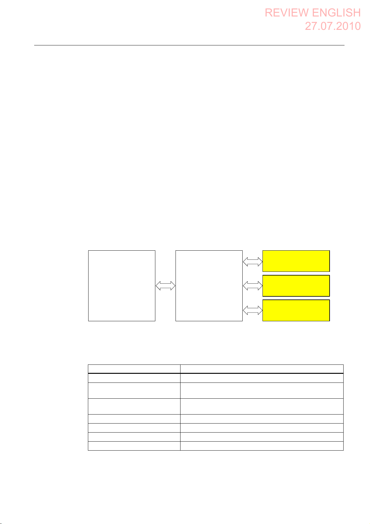
A.4 Application example RFID tag system
Flowchart
Function
Signal Explanation
Symbolic name
Enabling button ENABLE
(F_FB_RNG_4)
Power ON-OFF robot
O11.0 "0": EMERGENCY STOP triggered.
"E_Stop_Robot"
"0": No enable
"1": Enable
"1": Normal operation of plant.
Actuator to robot O11.1 "0": The robot is not operated with Key1 and the
enabling buttons
"1": The robot is operated with Key1 and the enabling
buttons
Signal lamp O 11.2 "0": Robot is not in use; the signal lamp is off
"1": Robot is in use; the signal lamp is on
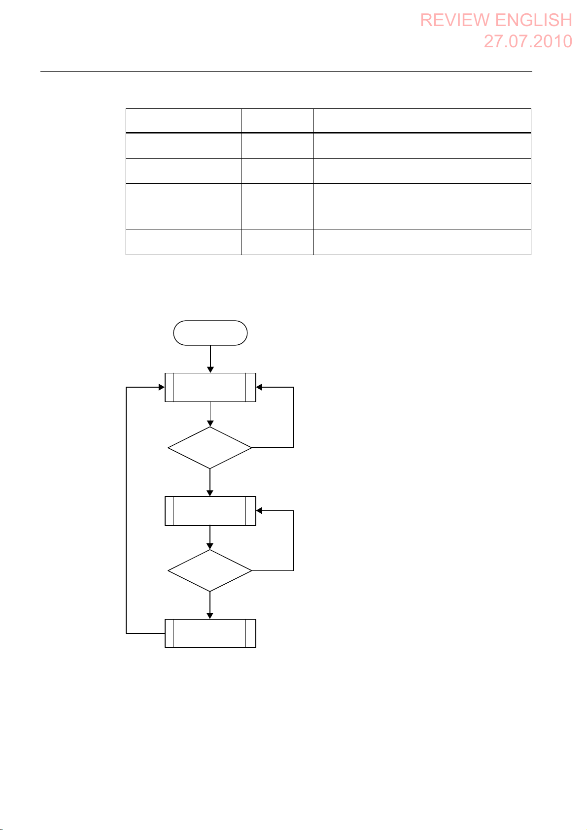
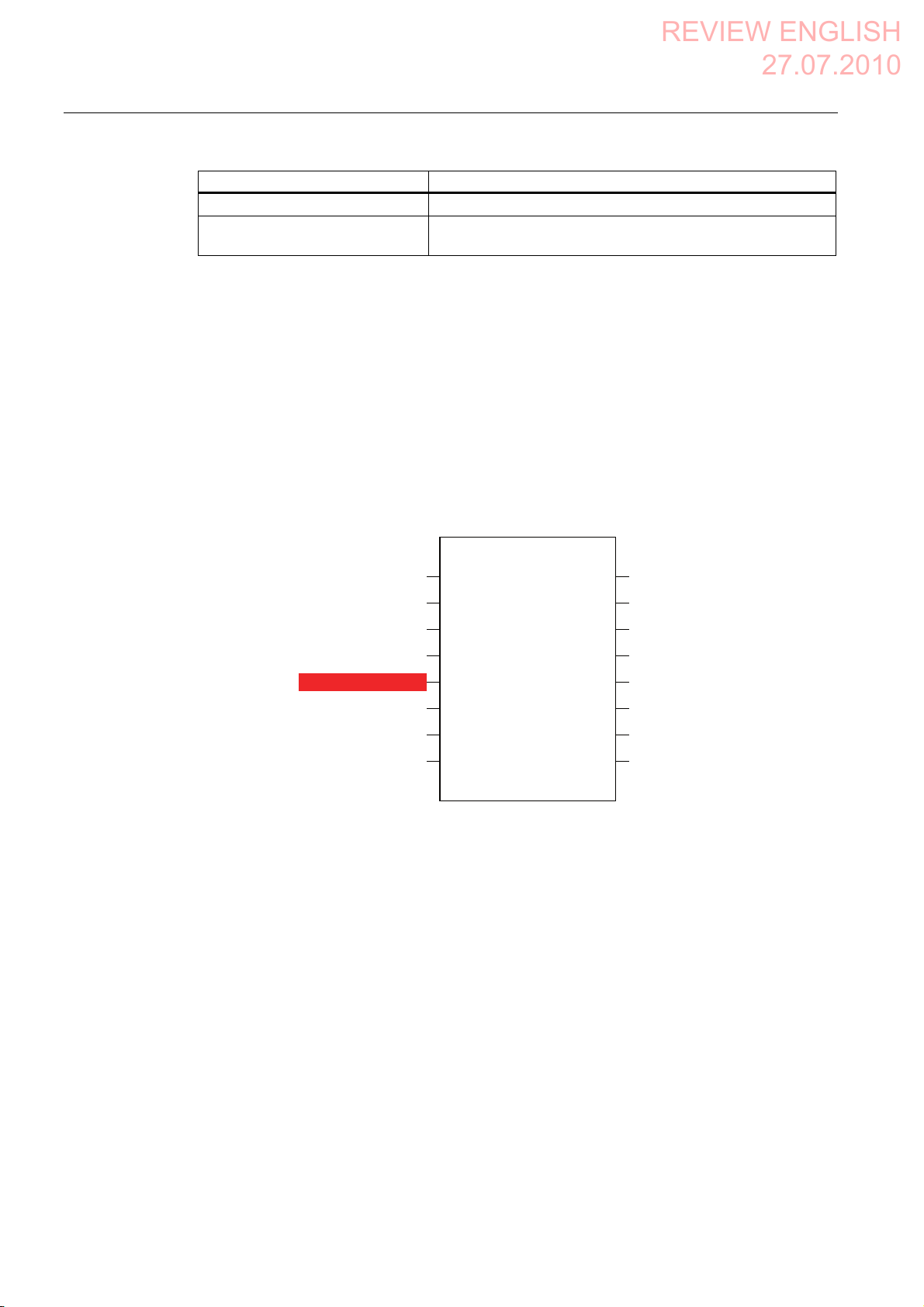
The following flowchart shows the operation sequence in the example.
Start
Operation in the
protection zone not
possible
Log on to the
machine?
Yes
Operation in the
protection zone is
possible
Contact with
pressure mat?
Yes
Forced logoff
No
No
Mobile Panel 277F IWLAN V2, Mobile Panel 277F IWLAN (RFID Tag)
400 Operating Instructions, 09/2010, A5E02766325-01
Page 2

Appendix
REVIEW ENGLISH
27.07.2010
A.4 Application example RFID tag system
A.4.2 Configuring the controller and HMI device in STEP 7
This section describes the most important parameters you need to set in "HW Config" for the
F-CPU and for the HMI device.
WARNING
Safety category
Any changes to parameters may result in the loss of the safety category.
Set the parameters as described. The parameters will contribute to meeting safety
category 4 PL e/SIL 3.
Requirement
The software for fail-safe operation has been installed, see section "Required software
(Page 25)".
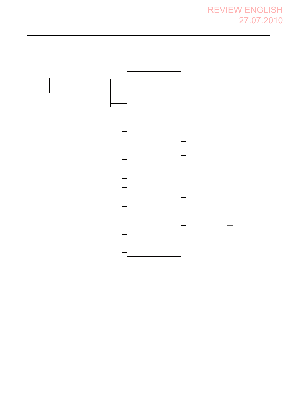
Procedure – Configuring CPU 317F-2 PN/DP
Proceed as follows:
1. Create a STEP 7 project in SIMATIC Manager.
2. Open the "HW Config" hardware configuration and insert the desired F-CPU and a
PROFINET connection, as shown in the following figure:
3. Open the settings by double-clicking the F-CPU in "HW Config".
Mobile Panel 277F IWLAN V2, Mobile Panel 277F IWLAN (RFID Tag)
Operating Instructions, 09/2010, A5E02766325-01
401
Page 3
Appendix
REVIEW ENGLISH
27.07.2010
A.4 Application example RFID tag system
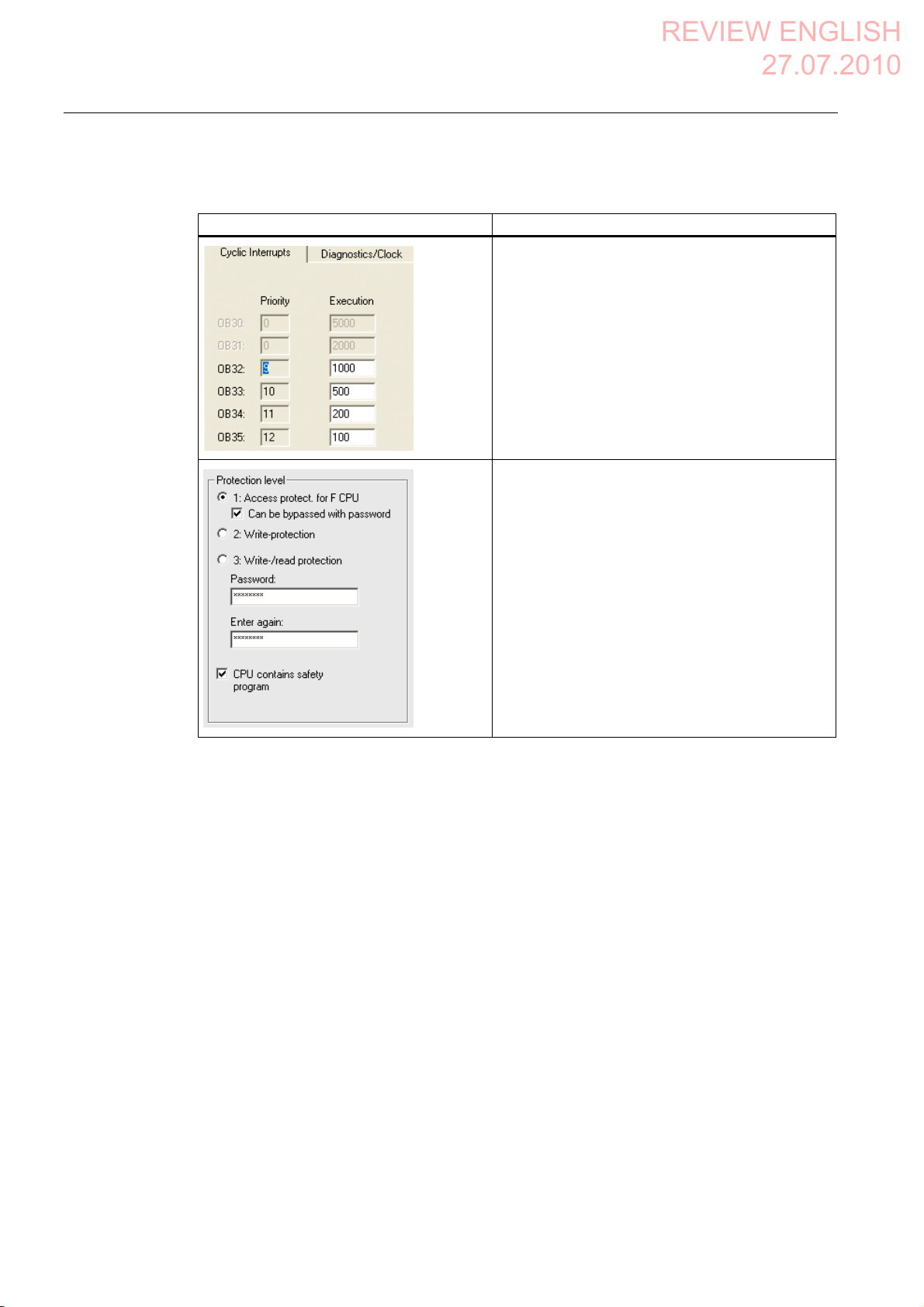
The table below shows the most important settings:
Setting Explanation
This is where you set the cycle time for OB35.
Note
If the cycle time for OB35 is set lower than the PBIO
update time, the message frame may be lost and the
evaluation of the "E-STOP" output of F_FB_RNG_4
or F_FB_RNG_16 may be delayed.
Set the cycle time of OB35 to a value higher than the
PNIO update time.
Assign a password for the safety program.
Set the "CPU contains safety program" check box.
This setting is required to generate all the necessary
F-FBs for safe operation of the fail-safe modules
during compilation of "HW Config" by STEP 7.
Mobile Panel 277F IWLAN V2, Mobile Panel 277F IWLAN (RFID Tag)
402 Operating Instructions, 09/2010, A5E02766325-01
Page 4
Appendix
REVIEW ENGLISH
27.07.2010
A.4 Application example RFID tag system
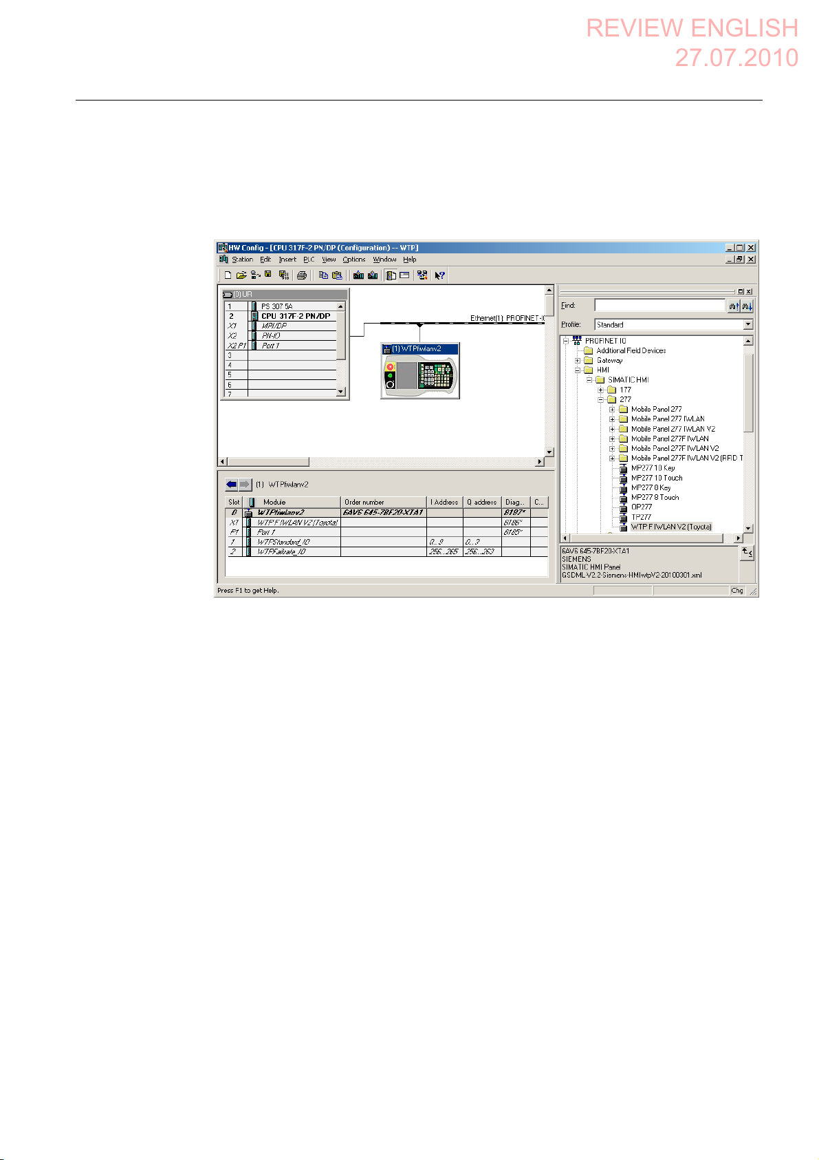
Procedure – Configuring Wireless Teach Pendant F IWLAN
Proceed as follows:
1. Insert the Wireless Teach Pendant F IWLAN in "HW Config" as shown in the following
figure.
2. Open the properties dialog of the HMI device by double-clicking the "WTPfiwlan" icon.
3. Enter the device name of the HMI device in the properties dialog.
4. Open the properties dialog of the "WTPFailsafe_IO" module by double-clicking the
"WTPFailsafe_IO" entry in the detailed view of the HMI device.
5. Change to the "PROFIsafe" tab.
The table below shows the most important settings:
Mobile Panel 277F IWLAN V2, Mobile Panel 277F IWLAN (RFID Tag)
Operating Instructions, 09/2010, A5E02766325-01
403
Page 5
Appendix
REVIEW ENGLISH
27.07.2010
A.4 Application example RFID tag system
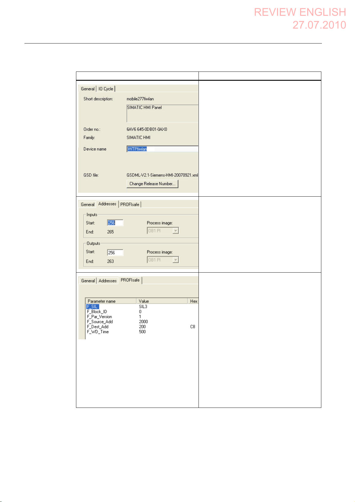
Setting Explanation
Device name
Here you assign a device name to the HMI
device, which is unique in the local Ethernet
network segment. This name must match the
name defined in the Control Panel of the HMI
device under "PROFINET" in the text box "Device
name:".
Additional information is available in the section:
"Specifying the computer nam
(Page 174)".
Inputs
This is where you specify the start address of the
inputs and the process image associated with this
address area (PII).
Outputs
Here you specify the start address of the outputs
and the process image associated with this
address area (PIQ).
e of the HMI device
F_Dest_Add
PROFIsafe address of the
Wireless Teach Pendant F IWLAN. This address
must match the address on the HMI device.
F_WD_Time
Monitoring time in the fail-safe IO device.
A valid current safety message frame must reach
the F-CPU and be returned to the HMI device
within the monitoring time period. This ensures
that failures and errors are detected and
appropriate responses are triggered to keep the
fail-safe system in a safe state or transfer it to a
safe state.
The monitoring time selected must be long
enough that message frame delays will be
tolerated by the communication system, but also
that the fault reaction function responds quickly
enough in the event of a fault (e.g. interruption in
the communication connection).
Mobile Panel 277F IWLAN V2, Mobile Panel 277F IWLAN (RFID Tag)
404 Operating Instructions, 09/2010, A5E02766325-01
Page 6
Appendix
REVIEW ENGLISH
27.07.2010
A.4 Application example RFID tag system
A.4.3 Safety program S7 Distributed Safety
In the safety program of the S7-CPU, the operation sequence of the application example is
implemented by the following programming:
● Once the HMI device is logged on to a machine, the signal lamp and the "Override" mode
are enabled.
● In the protection zone, the operator can operate the robot with the "Key1" button and the
enabling button.
● If the operator leaves the protection zone over the contact pressure mat, the safety
program responds as follows:
– The signal lamp goes out.
– "Override" mode is deactivated.
– The HMI device is logged off the machine.
● After an EMERGENCY STOP, the plant only restarts when the operator performs an
acknowledgment.
● Reactions specific to a plant are initiated when a rampdown or shutdown occurs.
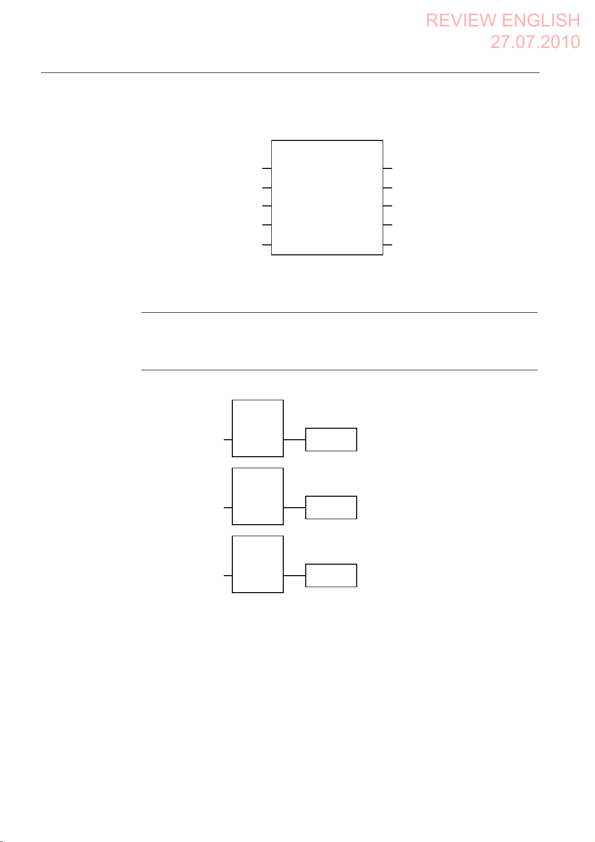
Safety program
Symbolic names
The safety program is structured as follows:
)&DOO
)%
)B)%B03))%
)&
)B)%B51*))%
)B(6723))%
The following symbolic names are used in the networks of the sample programs
Symbolic name Meaning
F00256_WTPFailsafe_IO Fail-safe I/O DB of HMI device
MP1_FB_S7_MP_RE Input which is set when a reset of the HMI device is performed
from the F-CPU.
MP1_FB_S7_ACK_ERR Input which is set when a communication error is acknowledged
from the F-CPU.
MP1_F_DATA_PII Word 1 of the PII of the HMI device
MP1_F_RANGE_PII Word 2 of the PII of the HMI device
MP1_F_DATA_PIQ Word 1 of the PIQ of the HMI device
MP1_F_RANGE_PIQ Word 2 of the PIQ of the HMI device
Mobile Panel 277F IWLAN V2, Mobile Panel 277F IWLAN (RFID Tag)
Operating Instructions, 09/2010, A5E02766325-01
405
Page 7
Appendix
REVIEW ENGLISH
27.07.2010
A.4 Application example RFID tag system
Symbolic name Meaning
Interface_DB F-DB for the data transfer of user data
F_DB_States F-DB for the transfer of data between the F_FB_MP of the HMI
device and the F_FB_RNG_n of the effective range
F-CALL (FC 1)
F-CALL (FC1) is the F-run-time group and is called from the cyclic interrupt OB (OB35).
F-CALL (FC1) calls the F-program block (in this case: FB1).
FB1
For reasons of program modularity, all other F-FBs are called from this FB.
In FB 1, you have to call the F-FBs in the following order.
1. Network 1
'%
)B)%B03
)B:73)DLOVDIHB,24%$'
)B:73)DLOVDIH B,2$&. B5(4
03B)%B6B03B5(
03B)%B6B$&.B(55
03B)B'$7$B3,,
03B)B51*B3,,
)B'%B67$7(603BB6WDWXV
(1
4%$'
$&.B 5(4
6B03B5(6
6B$&.B(55
03B'$7$
03B51*
03B67$7
03B'$7$B4
03B51*B4
$&.B 5(,
',$*
(12
)B:73)DLOVDIH B,2ಯ$&. B5(,
03B)B'$7$B3,4ಯ
03B)B51*B3,4
,QWHUIDFHB'%03B)%B',$*
The controller uses this F-FB to monitor the PROFIsafe communication of the HMI
device. The following diagnostics information is indicated at the "DIAG" output:
– Status of the HMI device: integrated or removed
– A communication error has occurred.
– Communication error must be acknowledged
Mobile Panel 277F IWLAN V2, Mobile Panel 277F IWLAN (RFID Tag)
406 Operating Instructions, 09/2010, A5E02766325-01
Page 8
Appendix
REVIEW ENGLISH
27.07.2010
A.4 Application example RFID tag system
2. Network 2
'%
(GJHB
&RQWDFWB
0DWV
&RQWDFWB0DWV
1(*
0B%,7 4
)B)%B51*B
(1
51*B,'
,QWHUIDFHB'%
(5B51*B%86<
03B)B'$7$B3,,
03B)B51*B3,,
)B'%B67$7(6
03BB6WDWXV
29(55,'(
03B'$7$
03B51*
03B)B.(<
03B'$7$
03B51*
03B)B.(<
03B'$7$
03B51*
03B)B.(<
03B'$7$
03B51*
03B)B.(<
03B67$7
03B67$7
03B67$7
(B6723
*/2%B5'
/2&B5'
6+87'2:1
(1$%/(
)B.(<6
51*B%86<
',$*
,QWHUIDFHB'%
(5B(B6723
,QWHUIDFHB'%
(5B*/2%B5'
,QWHUIDFHB'%
(5B/2&B5'
,QWHUIDFHB'%
(5B6+87'2:1
,QWHUIDFHB'%
(5B(1$%/(
,QWHUIDFHB'%
(5B51*B%86<
,QWHUIDFHB'%
(5B)%B',$*
03B67$7
The activation of the "override" mode is controlled in this network.
"OVERRIDE" is set as soon as the operator has logged the HMI device on to the machine
via the RFID tag. (RNG_BUSY). "OVERRIDE" is reset by a negative edge on the contact
pressure mat, in other words I11.0 = "0". This is the case when the operator leaves the
protection zone.
At the same time, F_FB_RNG monitors the signals "EMERGENCY STOP", "Global
rampdown", "Local rampdown" and "Shutdown". They are scanned in networks 3 to 6.
Mobile Panel 277F IWLAN V2, Mobile Panel 277F IWLAN (RFID Tag)
Operating Instructions, 09/2010, A5E02766325-01
(12
407
Page 9
Appendix
REVIEW ENGLISH
27.07.2010
A.4 Application example RFID tag system
3. Network 3
'%
)B(6723
,QWHUIDFHB'%(5B(B6723
(B6723
$&.B1(&
$&.
7,0(B'(/
4B'(/$<
$&.B5(4
',$*
(12
4
(B6WRSB5RERW(1
In network 3, the EMERGENCY STOP signal of the HMI device is monitored via
F_ESTOP1 from the F-library of S7 Distributed Safety. F_ESTOP1 ensures that the plant
is only able to restart following an EMERGENCY STOP after acknowledgment by the
operator via the input "ACK".
Note
Read also the information on FB215 in the online help for F-FBs and in the manual
"SIMATIC S7-Distributed Safety, Configuring and Programming", section "FB215
"F_ESTOP1:" Emergency STOP up to Stop Category 1".
4. Networks 4, 5 and 6
*OREDOB5DPSGRZQ
,QWHUIDFHB'%
(5B*/2%B5'
RF
DOB5DPSGRZQ
/
,QWHUIDFHB'%
(5B/2&B5'
,QWHUIDFHB'%
(5B6+87'2:1
6KXWGRZQ
In network 4, 5 and 6 the signals for a global and a local rampdown and shutdown are
processed further. As the configuration of the monitored plant determines which
responses have to occur following occurrence of a particular safety state, these networks
are not explained in detail in this example.
Mobile Panel 277F IWLAN V2, Mobile Panel 277F IWLAN (RFID Tag)
408 Operating Instructions, 09/2010, A5E02766325-01
Page 10
Appendix
REVIEW ENGLISH
27.07.2010
A.5 Safety-related messages
5. Network 7
(
,QWHUIDFHB'%
(5B(QDEOH
If the operator simultaneously presses the Key1 key and the enabling button, the robot is
activated via the output Q11.1.
6. Network 8
,QWHUIDFHB'%
(5B51*B%86<
If the "RNG_BUSY" signal is set in F_FB_RNG, output Q11.2 is used to control the signal
lamp that indicates whether or not the machine is in use.
A.5 Safety-related messages
A.5.1 Transponder system
$
$
The following safety-related messages are displayed in fail-safe mode depending on the
operating situation. In contrast to system alarms, no message window needs to be
configured for safety-related messages.
NOTICE
Function keys inactive for the display length of the alarm
While a safety-related alarm is shown, the function keys of the HMI device are inactive.
Close the window of the safety-related alarm in order to reactivate the function keys.
Mobile Panel 277F IWLAN V2, Mobile Panel 277F IWLAN (RFID Tag)
Operating Instructions, 09/2010, A5E02766325-01
409
Page 11
Appendix
REVIEW ENGLISH
27.07.2010
A.5 Safety-related messages
Dialog Reaction Situation
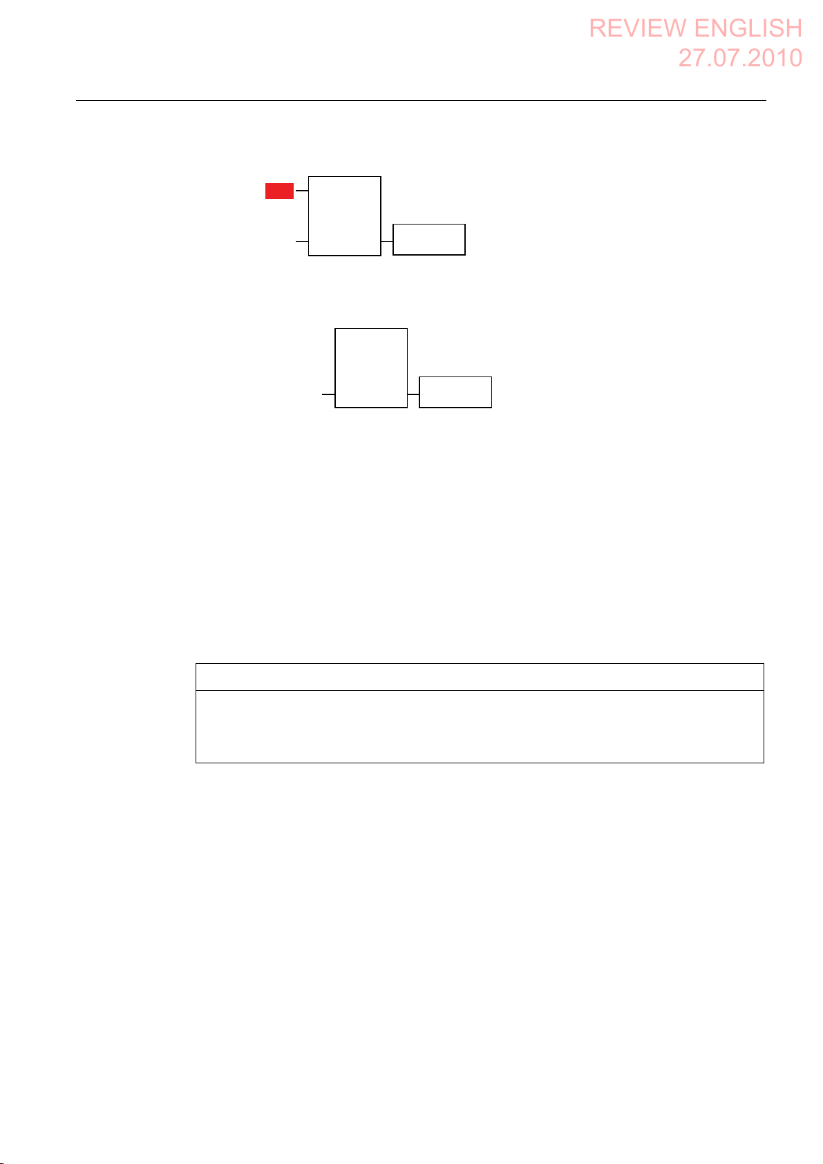
Establishment of safety connection
No safe connection available.
Reason:
Connection not yet completed
PROFIsafe address error
Internal configuration error
Communication error (timeout)
Communication error (CRC)
CPU in STOP
PROFIsafe CRC configuration
error
Should the Panel be switched off?
Start removal
The removal cannot be interrupted
once it has started.
Do you want to start the removal?
Confirm removal
"Yes" button The following is reported in the warning
message depending on the operating
situation:
Connection not yet completed
The safe connection is not yet
established after the project has been
started. Wait until the connection has
been established. The dialog is closed
on completion.
A communication error occurred after
the HMI device was successfully
integrated. Correct the cause of the
error described by "Reason".
"Yes" button
"No" button
Press an enabling
button until the
"Enable" switch
position is reached.
The "Start removal" dialog opens in the
following cases:
The operator has pressed the
"ON/OFF" button for more than
4 seconds.
The operator has pressed the operator
control for closing the project.
The removal starts, in other word, the user
has pressed the "Yes" button in the "Start
removal" dialog.
Please confirm the removal with
the enabling button.
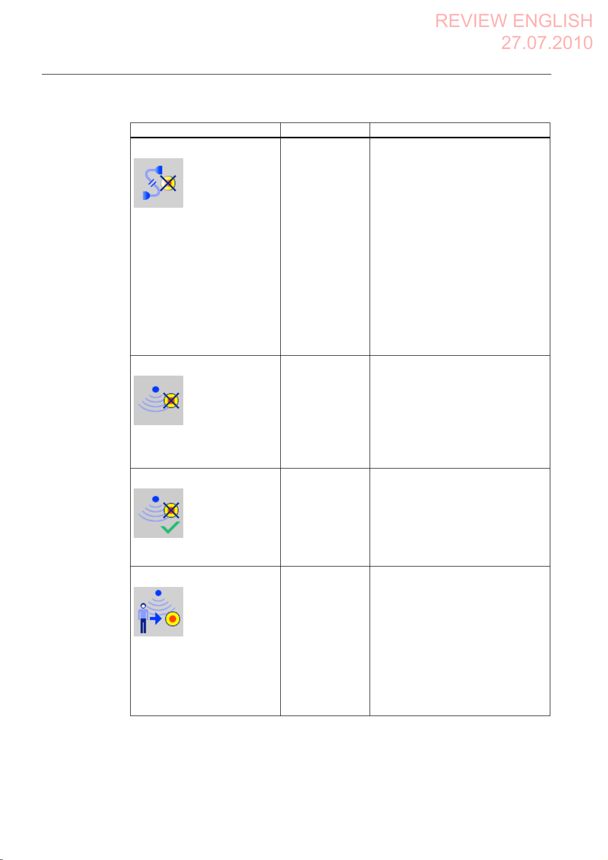
Effective range logon
Do you want to logon to the
following effective range?
Effective range <<EFFECTIVE
RANGE NAME>>
Please enter the effective range
ID:
Mobile Panel 277F IWLAN V2, Mobile Panel 277F IWLAN (RFID Tag)
410 Operating Instructions, 09/2010, A5E02766325-01
"Yes" button
"No" button
The HMI device is located within an
effective range but it is not logged on.
The operator has activated the white
"Effective range name" object to log on.
Page 12
Appendix
REVIEW ENGLISH
27.07.2010
A.5 Safety-related messages
Dialog Reaction Situation
Effective range logoff
"Yes" button
"No" button
The HMI device is logged onto the
effective range. The operator has
activated the "Effective range name"
object to log off.
Do you want to log off from the
following effective range?
Effective range <<EFFECTIVE
RANGE NAME>>
Effective range logoff (shutdown)
The Panel cannot be switched off.
You first have to log off from the
effective range.
Do you want to logoff from the
following effective range?
Effective range <<EFFECTIVE
RANGE NAME>>
Acknowledgment of
communication error
A safe connection is possible
again. Please confirm the
communication error.
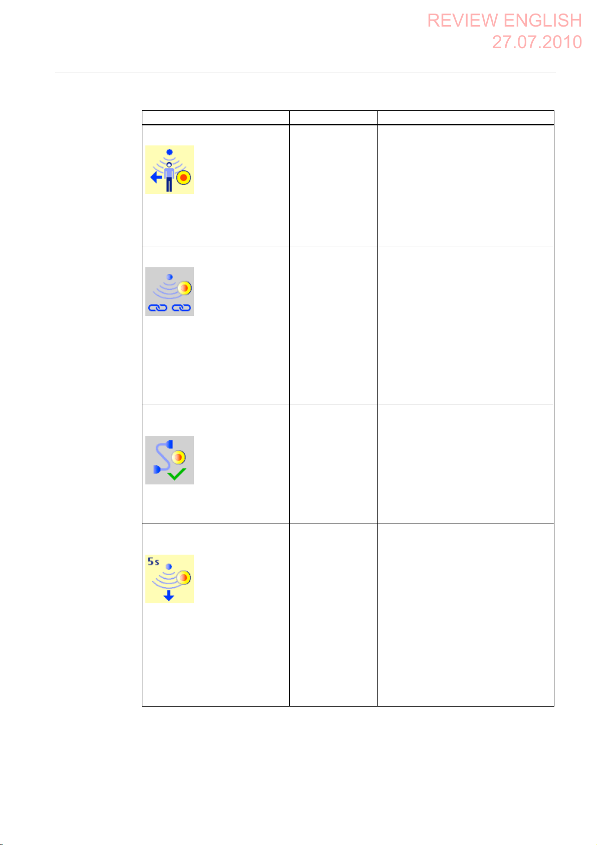
Effective range exited without
logoff(5 seconds)
"Yes" button
"No" button
"OK" button Communication was recovered after a
"Yes" button
or
Return to the
effective range
within 25 seconds
The HMI device is logged on to a
machine.
The operator has attempted to:
Shut down the HMI device.
Close the project with the
corresponding operator control.
short communication error. The operator
must confirm this state.
Causes:
The operator has briefly left the WLAN
range and then returned.
PROFIsafe communication was briefly
interrupted.
The operator has left the effective range
with the logged on HMI device for more
than 5 seconds.
WARNING: You have exited the
following effective range without
logging off:
Effective range <<EFFECTIVE
RANGE NAME>>
The enabling button is deactivated.
Do you want to log off from the
effective range?
Mobile Panel 277F IWLAN V2, Mobile Panel 277F IWLAN (RFID Tag)
Operating Instructions, 09/2010, A5E02766325-01
411
Page 13
Appendix
REVIEW ENGLISH
27.07.2010
A.5 Safety-related messages
Dialog Reaction Situation
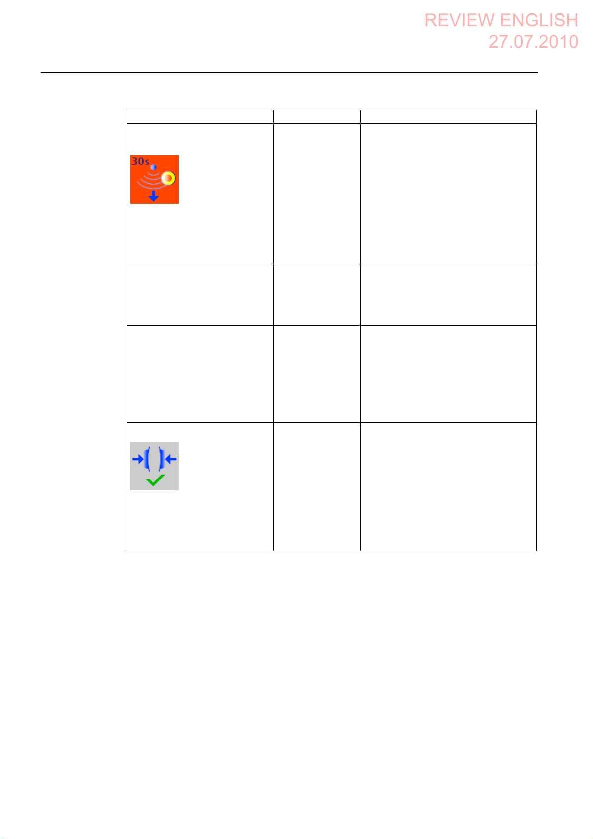
Effective range exited without
logoff(30 seconds)
"OK" button The operator has left the effective range
with the logged on HMI device for more
than 30 seconds.
You have left the effective range
without permission. A local
shutdown was initiated! Please
confirm logging off from the
effective range.
Low battery alarm
Battery charge is less than 20
percent.
Testing transponders
This dialog contains no coherent
text.
Users are informed that they are in
a mode for testing the
transponders. The user muss test
all transponders in all effective
ranges.
Test enabling button
"OK" button The remaining charge of the main
rechargeable battery is less than 20%.
An additional system alarm is output after
the charge of the main rechargeable
battery has dropped to less than 6%.
Diverse A project has been started on the HMI
device that does not contain an up-to-date
CRC checksum for the effective ranges.
The effective ranges and transponders
need to be tested using the dialog.
Press both enabling
buttons until the
"Panic" switch
position is reached.
The operator has started the project.
Perform a function test for the enabling
button.
Both enabling buttons must be
tested to ensure they are
operational. Fully press both
enabling buttons until the panic
position is reached.
Mobile Panel 277F IWLAN V2, Mobile Panel 277F IWLAN (RFID Tag)
412 Operating Instructions, 09/2010, A5E02766325-01
Page 14
Appendix
REVIEW ENGLISH
27.07.2010
A.5 Safety-related messages
Dialog Reaction Situation
Error during effective range logon
Error during effective range logon.
The enabling button remains
deactivated.
"OK" button An error occurred during logon of the HMI
device to a machine. The operator cannot
use the enable switches to control the
production process.
Possible causes:
You are already logged on to the
machine with your HMI device or the
logon is currently in progress.
Another HMI device is already logged
on to the machine.
Transponder defective.
Effective range module in the HMI
device is defective.
No ID has been assigned to the
transponder.
The operator has entered an incorrect
effective range ID for the logon.
F_FB_RNG missing in the STEP7
configuration.
F_FB_RNG is wired incorrectly in
STEP7.
Enabling switch discrepancy error
Please release the enabling
button.
A.5.2 RFID tag system
The following safety-related messages are displayed in fail-safe mode depending on the
operating situation. In contrast to system alarms, no message window needs to be
configured for safety-related messages.
NOTICE
Function keys inactive for the display length of the alarm
While a safety-related alarm is shown, the function keys of the HMI device are inactive.
Close the window of the safety-related alarm in order to reactivate the function keys.
Release both
enabling buttons.
The HMI device detects a discrepancy at
one of the two enabling buttons in switch
position "Enable".
Mobile Panel 277F IWLAN V2, Mobile Panel 277F IWLAN (RFID Tag)
Operating Instructions, 09/2010, A5E02766325-01
413
Page 15
Appendix
REVIEW ENGLISH
27.07.2010
A.5 Safety-related messages
Dialog Reaction Situation
Establishment of safety connection
No safe connection available.
Reason:
Connection not yet completed
PROFIsafe address error
Internal configuration error
Communication error (timeout)
Communication error (CRC)
CPU in STOP
PROFIsafe CRC configuration
error
Should the Panel be switched off?
Start removal
The removal cannot be interrupted
once it has started.
Do you want to start the removal?
Confirm removal
"Yes" button The following is reported in the warning
message depending on the operating
situation:
Connection not yet completed
The safe connection is not yet
established after the project has been
started. Wait until the connection has
been established. The dialog is closed
on completion.
A communication error occurred after
the HMI device was successfully
integrated. Correct the cause of the
error described by "Reason".
"Yes" button
"No" button
Press an enabling
button until the
"Enable" switch
position is reached.
The "Start removal" dialog opens in the
following cases:
The operator has pressed the
"ON/OFF" button for more than
4 seconds.
The operator has pressed the operator
control for closing the project.
The removal starts, in other word, the user
has pressed the "Yes" button in the "Start
removal" dialog.
Please confirm the removal with
the enabling button.
Effective range logon
Do you want to logon to the
following effective range?
Effective range <<EFFECTIVE
RANGE NAME>>
Please enter the effective range
ID:
Mobile Panel 277F IWLAN V2, Mobile Panel 277F IWLAN (RFID Tag)
414 Operating Instructions, 09/2010, A5E02766325-01
"Yes" button
"No" button
The HMI device is located directly in front
of an RFID tag and is not yet logged on to
the corresponding machine.
The operator has activated the "Scan"
object to log on.
6FDQ
Page 16
Appendix
REVIEW ENGLISH
27.07.2010
A.5 Safety-related messages
Dialog Reaction Situation
Effective range logoff
"Yes" button
"No" button
The HMI device is logged on to a
machine.
The operator has activated the "Effective
range name (RFID)" object to log off.
Do you want to log off from the
following effective range?
Effective range <<EFFECTIVE
RANGE NAME>>
Effective range logoff (shutdown)
The Panel cannot be switched off.
You first have to log off from the
effective range.
Do you want to logoff from the
following effective range?
Effective range <<EFFECTIVE
RANGE NAME>>
Acknowledgment of
communication error
A safe connection is possible
again. Please confirm the
communication error.
Forced logoff
"Yes" button
"No" button
"OK" button Communication was recovered after a
"OK" button The operator has left the protection zone
The HMI device is logged on to a
machine.
The operator has attempted to:
Shut down the HMI device.
Close the project with the
corresponding operator control.
short communication error. The operator
must confirm this state.
Causes:
The operator has briefly left the WLAN
range and then returned.
PROFIsafe communication was briefly
interrupted.
with a logged-on HMI device via the safety
system.
You are automatically logged off
from the effective range.
A local rampdown has been
triggered! Confirm the logoff from
the effective range.
Low battery alarm
Battery charge is less than 20
percent.
Mobile Panel 277F IWLAN V2, Mobile Panel 277F IWLAN (RFID Tag)
Operating Instructions, 09/2010, A5E02766325-01
"OK" button The remaining charge of the main
rechargeable battery is less than 20%.
An additional system alarm is output after
the charge of the main rechargeable
battery has dropped to less than 6%.
415
Page 17
Appendix
REVIEW ENGLISH
27.07.2010
A.6 System alarms
Dialog Reaction Situation
Test enabling button
Press both enabling
buttons until the
"Panic" switch
position is reached.
The operator has started the project.
Perform a function test for the enabling
button.
Both enabling buttons must be
tested to ensure they are
operational. Fully press both
enabling buttons until the panic
position is reached.
Error during effective range logon
Error during effective range logon.
The enabling button remains
deactivated.
"OK" button An error occurred during logon of the HMI
device to a machine. The operator cannot
use the enable switches to control the
production process.
Possible causes:
You are already logged on to the
machine with your HMI device or the
logon is currently in progress.
Another HMI device is already logged
on to the machine.
RFID tag is defective.
RFID module in the HMI device is
defective.
No ID has been assigned to the RFID
tag.
The operator has entered an incorrect
RFID tag ID for the logon.
F_FB_RNG missing in the STEP7
configuration.
F_FB_RNG is wired incorrectly in
STEP7.
Enabling switch discrepancy error
Release both
enabling buttons.
The HMI device detects a discrepancy at
one of the two enabling buttons in switch
position "Enable".
Please release the enabling
button.
A.6 System alarms
Introduction
System alarms on the HMI device provide information about internal states of the HMI device
and PLC.
Mobile Panel 277F IWLAN V2, Mobile Panel 277F IWLAN (RFID Tag)
416 Operating Instructions, 09/2010, A5E02766325-01
Page 18

Appendix
REVIEW ENGLISH
27.07.2010
A.6 System alarms
The following overview shows the causes of system alarms and how to eliminate the cause
of error.
Some of the system alarms described in this section are relevant to individual HMI devices
based on their range of features.
Note
System alarms are only indicated if an alarm window was configured. System alarms are
output in the language currently set on your HMI device.
System alarm parameters
System alarms may contain encrypted parameters which are relevant to troubleshooting
because they provide a reference to the source code of the runtime software. These
parameters are output after the text "Error code:"
Displaying the "System alarms" editor
You can find the text content of the system alarm in WinCC flexible. The "System alarms"
editor is not displayed by default in WinCC flexible.
1. Enable the "System alarms" editor under "Options > Setting... > Workbench > Settings for
Project Window" with "Display all entries".
2. Select the "System alarms" editor under "Alarms" in the project view.
The system alarms are sorted numerically in the "System alarms" editor.
Configuring events for system alarms
You can configure the "Incoming" event for the following system alarm in the "System
alarms" editor.
System alarms
10000
10000 to 10006
150000
150000
150001
230300
230300 to 230308
20000
20000 to 20015
30000
30010 to 20012
Mobile Panel 277F IWLAN V2, Mobile Panel 277F IWLAN (RFID Tag)
Operating Instructions, 09/2010, A5E02766325-01
160000
160000
160001
160010 to 160014
170000
170000 to 170004
170007
240000
240000 to 240005
250000
250000 to 250003
417
Page 19

Appendix
REVIEW ENGLISH
27.07.2010
A.6 System alarms
System alarms
40000
40010
40011
180000
180000 to 180002
260000
260000 to 260009
260012 to 260014
260028
260030
260033 to 260045
50000
50000
50001
60000
60010 to 60011
70000
70010 to 70044
80000
80001 to 80035
80044 to 80050
90000
90024 to 90026
90029 to 90033
90040
90041
90044
190000
190000 to 190002
190004 to 190013
190100
190100 to 190102
200000
200000 to 200005
200100
200100 to 200105
210000
210000 to 210006
270000
270000 to 270003
280000
280000 to 280004
290000
290000 to 290008
290010 to 290014
290020 to 290027
290040 to 290042
290044
290050 to 290065
290070 to 290073
290075
300000
300000
300001
310000
310000
310001
110000
110000 to 110006
120000
120000 to 120002
130000
130000 to 130012
140000
140000 to 140020
Mobile Panel 277F IWLAN V2, Mobile Panel 277F IWLAN (RFID Tag)
418 Operating Instructions, 09/2010, A5E02766325-01
220000
220000 to 220008
230000
230000
230002
200003
200005
230100
230100
230200
230200 to 230203
600000
600000
620000
620000
Page 20

Appendix
REVIEW ENGLISH
27.07.2010
A.6 System alarms
10000 - Printer alarms
Number Effect/cause Remedy
10000 The print job could not be started or was canceled
due to an unknown error. Faulty printer setup. Or:
No authorization is available for accessing the
network printer.
Power supply failure during data transfer.
10001 No printer is installed or a default printer has not
been set up.
10002 Overflow of the graphics buffer for printing. Up to
two graphics are buffered.
10003 Graphics can now be buffered again. -10004 Overflow of the buffer for printing lines in text mode
(e.g. alarms). Up to 1000 lines are buffered.
10005 Text lines can now be buffered again. -10006 The Windows printing system reports an error.
Refer to the output text and the error ID to
determine the possible causes. Nothing is printed
or the print is faulty.
Check the printer settings, cable connections and the
power supply.
Set up the printer once again. Obtain a network printer
authorization.
If the error persists, contact the Hotline!
Install a printer and/or select it as the default printer.
Allow sufficient intervals between successive print jobs.
Allow sufficient intervals between successive print jobs.
Repeat the action if necessary.
20000 - Global script alarms
Number Effect/causes Remedy
20010 An error has occurred in the specified script line.
Execution of the script was therefore aborted. Note
the system alarm that may have occurred prior to
this.
20011 An error has occurred in a script that was called by
the specified script.
Execution of the script was therefore aborted in the
called script.
Note the system alarm that may have occurred
prior to this.
20012 The configuration data is inconsistent. The script
could therefore not be generated.
20013 The scripting component of WinCC flexible
Runtime is not correctly installed. Therefore, no
scripts can be executed.
20014 The system function returns a value that is not
written in any return tag.
20015 Too many successive scripts have been triggered
in short intervals. When more than 20 scripts are
queued for processing, any subsequent scripts are
rejected. In this case, the script indicated in the
alarm is not executed.
Select the specified script line in the configuration.
Ensure that the tags used are of the allowed types.
Check system functions for the correct number and
types of parameters.
In the configuration, select the script that has been
called directly or indirectly by the specified script.
Ensure that the tags used are of the allowed types.
Check system functions for the correct number and
types of parameters.
Recompile the configuration.
Reinstall WinCC flexible Runtime on your PC.
Rebuild your project with "Project > Compiler >
Generate" and transfer the project to the HMI device.
Select the specified script in the configuration.
Check whether the script name has been assigned a
value.
Find what is triggering the scripts. Extend the times,
e.g. the polling time of the tags which trigger the
scripts.
Mobile Panel 277F IWLAN V2, Mobile Panel 277F IWLAN (RFID Tag)
Operating Instructions, 09/2010, A5E02766325-01
419
Page 21

Appendix
REVIEW ENGLISH
27.07.2010
A.6 System alarms
30000 - Alarms for IFwSetValue: SetValue()
Number Effect/causes Remedy
30010 The tag could not accept the function result, e.g.
when it has exceeded the value range.
30011 A system function could not be executed because
the function was assigned an invalid value or type
in the parameter.
30012 A system function could not be executed because
the function was assigned an invalid value or type
in the parameter.
Check the tag type of the system function parameter.
Check the parameter value and tag type of the invalid
parameter. If a tag is used as a parameter, check its
value.
Check the parameter value and tag type of the invalid
parameter. If a tag is used as a parameter, check its
value.
40000 - Linear scaling alarms
Number Effect/causes Remedy
40010 The system function could not be executed since
the parameters could not be converted to a
common tag type.
40011 The system function could not be executed since
the parameters could not be converted to a
common tag type.
Check the parameter types in the configuration.
Check the parameter types in the configuration.
50000 - Data server alarms
Number Effect/causes Remedy
50000 The HMI device is receiving data faster than it is
capable of processing. Therefore, no further data is
accepted until all current data have been
processed. Data exchange then resumes.
50001 Data exchange has been resumed. --
--
60000 - Win32 function alarms
Number Effect/causes Remedy
60000 This alarm is generated by the
“DisplaySystemAlarms” function. The text to be
displayed is transferred to the function as a
parameter.
60010 The file could not be copied in the direction defined
because one of the two files is currently open or the
source/target path is not available.
It is possible that the Windows user has no access
rights to one of the two files.
60011 An attempt was made to copy a file to itself.
It is possible that the Windows user has no access
rights to one of the two files.
--
Restart the system function or check the paths of the
source/target files. Using Windows NT/XP: The user
running WinCC flexible Runtime must be granted
access rights to the files.
Check the path of the source/target file.
Using Windows NT/XP with NTFS: The user running
WinCC flexible Runtime must be granted access rights
to the files.
Mobile Panel 277F IWLAN V2, Mobile Panel 277F IWLAN (RFID Tag)
420 Operating Instructions, 09/2010, A5E02766325-01
Page 22

Appendix
REVIEW ENGLISH
27.07.2010
A.6 System alarms
70000 - Win32 function alarms
Number Effect/causes Remedy
70010 The application could not be started because it
could not be found in the path specified or there is
insufficient memory space.
70011 The system time could not be modified.
The error alarm only appears in connection with
area pointer "Date/time PLC". Possible causes:
An invalid time was transferred in the job
mailbox.
The Windows user has no right to modify the
system time.
If the first parameter in the system alarm is
displayed with the value 13, the second parameter
indicates the byte containing the incorrect value.
70012 An error occurred when executing the function
"StopRuntime" with the option "Runtime and
operating system".
Windows and WinCC flexible Runtime are not
closed.
One possible cause is that other programs cannot
be closed.
70013 The system time could not be modified because an
invalid value was entered. Incorrect separators may
have been used.
70014 The system time could not be modified. Possible
causes:
An invalid time was transferred.
The Windows user has no right to modify the
system time.
Windows rejects the setting request.
70015 The system time could not be read because
Windows rejects the reading function.
70016 An attempt was made to select a screen by means
of a system function or job. This is not possible
because the screen number specified does not
exist.
Or: A screen could not be generated due to
insufficient system memory.
Or: The screen is blocked.
Or: Screen call has not been executed correctly.
70017 Date/time is not read from the area pointer because
the address set in the PLC is either not available or
has not been set up.
70018 Acknowledgment that the password list has been
successfully imported.
70019 Acknowledgment that the password list has been
successfully exported.
70020 Acknowledgment for activation of alarm reporting. --
Check whether the application exists in the specified
path or close other applications.
Check the time which is to be set.
Using Windows NT/XP: Users running WinCC flexible
Runtime must be granted the right to modify the
system time of the operating system.
Close all programs currently running.
Then close Windows.
Check the time which is to be set.
Check the time which is to be set.
Using Windows NT/XP: Users running WinCC flexible
Runtime must be granted the right to modify the
system time of the operating system.
--
Check the screen number in the function or job with the
screen numbers configured.
Assign the number to a screen if necessary.
Check the details for the screen call and whether the
screen is blocked for specific users.
Change the address or set up the address in the PLC.
--
--
Mobile Panel 277F IWLAN V2, Mobile Panel 277F IWLAN (RFID Tag)
Operating Instructions, 09/2010, A5E02766325-01
421
Page 23

Appendix
REVIEW ENGLISH
27.07.2010
A.6 System alarms
Number Effect/causes Remedy
70021 Acknowledgment for deactivation of alarm
reporting.
70022 Acknowledgment to starting the Import Password
List action.
70023 Acknowledgment to starting the Export Password
List action.
70024 The range of values of the tag was exceeded in the
system function.
No calculation of the system function.
70025 The range of values of the tag was exceeded in the
system function.
No calculation of the system function.
70026 No other screens are stored in the internal screen
memory.
No other screens can be selected.
70027 The backup of the RAM file system has been
started.
70028 The files from the RAM have been copied in the
Flash memory.
The files from the RAM have been copied in the
Flash memory. Following a restart, these saved
files are copied back to the RAM file system.
70029 Backup of the RAM file system has failed.
No backup copy of the RAM file system has been
made.
70030 The parameters configured for the system function
are faulty.
The connection to the new PLC was not
established.
70031 The PLC configured in the system function is not
an S7 PLC.
The connection to the new PLC was not
established.
70032 The object configured with this number in the tab
order is not available in the selected screen.
The screen changes but the focus is set to the first
object.
70033 An e-mail cannot be sent because a TCP/IP
connection to the SMTP server no longer exists.
This system alarm is generated only at the first
attempt. All subsequent unsuccessful attempts to
send an e-mail will no longer generate a system
alarm. The event is regenerated when an e-mail
has been successfully sent in the meantime.
The central e-mail component in WinCC flexible
Runtime attempts, in regular intervals (1 minute), to
establish the connection to the SMTP server and to
send the remaining e-mails.
70034 Following a disruption, the TCP/IP connection to
the SMTP server could be re-established.
The queued e-mails are then sent.
--
--
--
Check and correct the calculation.
Check and correct the calculation.
--
--
--
Check the settings in the "Control Panel > OP" dialog
and save the RAM file system using the "Save Files"
button in the "Persistent Storage" tab.
Compare the parameters configured for the system
function with the parameters configured for the PLCs
and correct them as necessary.
Compare the S7 PLC name parameter configured for
the system function with the parameters configured for
the PLC and correct them as necessary.
Check the number of the tab order and correct it if
necessary.
Check the network connection to the SMTP server and
re-establish it if necessary.
--
Mobile Panel 277F IWLAN V2, Mobile Panel 277F IWLAN (RFID Tag)
422 Operating Instructions, 09/2010, A5E02766325-01
Page 24

Appendix
REVIEW ENGLISH
27.07.2010
A.6 System alarms
Number Effect/causes Remedy
70036 No SMTP server for sending e-mails is configured.
An attempt to connect to an SMTP server has
failed and it is not possible to send e-mails.
WinCC flexible Runtime generates the system
alarm after the first attempt to send an e-mail.
70037 An e-mail cannot be sent for unknown reasons.
The contents of the e-mail are lost.
70038 The SMTP server has rejected sending or
forwarding an e-mail because the domain of the
recipient is unknown to the server or because the
SMTP server requires authentication.
The contents of the e-mail are lost.
70039 The syntax of the e-mail address is incorrect or
contains illegal characters.
The contents of the e-mail are discarded.
70040 The syntax of the e-mail address is incorrect or
contains illegal characters.
70041 The import of the user management was aborted
due to an error.
Nothing was imported.
70042 The range of values of the tag was exceeded while
executing the system function.
The system function was not calculated.
70043 The range of values of the tag was exceeded while
executing the system function.
The system function was not calculated.
70044 An error occurred while sending the e-mails. The e-
mails were not sent.
70045 Cannot load a file required for encrypting the e-
mail.
70046 The server does not support encryption. Select an SMTP server that supports encryption.
70047 The SSL versions of the HMI device and SMTP
server may not be compatible.
Configure an SMTP server:
In WinCC flexible Engineering System
using "Device settings > Device settings"
In the Windows CE operating system
using "Control Panel > Internet Settings > E-mail >
SMTP Server"
Check the e-mail parameters (recipient etc.).
Check the domain of the recipient address or disable
the authentication on the SMTP server if possible.
SMTP authentication is currently not used in
WinCC flexible Runtime.
Check the e-mail address of the recipient.
--
Check your user management or transfer it again to
the panel.
Check and correct the calculation.
Check and correct the calculation.
Check the SMTP settings and the error message in the
system alarm.
Update the operating system and Runtime.
Contact your network administrator or the operator of
the SMTP server.
80000 - Log alarms
Number Effect/causes Remedy
80001 The log specified is filled to the size defined (in
percent) and must be stored elsewhere.
80002 A line is missing in the specified log. -80003 The copying process for logging was not
successful.
In this case, it is advisable to check any
subsequent system alarms, too.
Mobile Panel 277F IWLAN V2, Mobile Panel 277F IWLAN (RFID Tag)
Operating Instructions, 09/2010, A5E02766325-01
Store the file or table by executing a ‘move’ or ‘copy’
function.
--
423
Page 25

Appendix
REVIEW ENGLISH
27.07.2010
A.6 System alarms
Number Effect/causes Remedy
80006 Since logging is not possible, this causes a
permanent loss of the functionality.
80009 A copying action has been completed successfully. -80010 Since the storage location was incorrectly entered
in WinCC flexible, this causes a permanent loss of
the functionality.
80012 Log entries are stored in a buffer. If the values are
read to the buffer faster than they can be physically
written (using a hard disk, for example),
overloading may occur and recording is then
stopped.
80013 The overload status no longer applies. Archiving
resumes the recording of all values.
80014 The same action was triggered twice in quick
succession. Since the process is already in
operation, the action is only carried out once.
80015 This system alarm is used to report DOS or
database errors to the user.
80016 The logs are separated by the system function
"CloseAllLogs" and the incoming entries exceed
the defined buffer size.
All entries in the buffer are deleted.
80017 The number of incoming events cause a buffer
overflow. This can be caused, for example, by
several copying actions being activated at the
same time.
All copy jobs in the buffer are deleted.
80019 The connection between WinCC flexible and all
logs were closed, for example, after executing the
system function "CloseAllLogs".
Entries are written to the buffer and are then written
to the logs when a connection is re-established.
There is no connection to the storage location and
the storage medium may be replaced, for example.
80020 The maximum number of simultaneously copy
operations has been exceeded. Copying is not
executed.
80021 An attempt was made to delete a log which is still
busy with a copy action. Deletion has not been
executed.
80022 An attempt was made to use the system function
"StartSequenceLog" to start a sequence log for a
log which is not configured as a sequence log. No
sequence log file is created.
In the case of databases, check whether the
corresponding data source exists and start up the
system again.
Configure the storage location for the respective log
again and restart the system when the full functionality
is required.
Archive fewer values.
Or:
Increase the logging cycle.
--
--
--
Reconnect the logs.
Stop the copy action.
--
Wait until the current copying actions have been
completed, then restart the last copy action.
Wait until the current copying actions have been
completed, then restart the last action.
In the project, check
if the "StartSequenceLog" system function was
properly configured.
if the tag parameters are properly provided with
data on the HMI device.
Mobile Panel 277F IWLAN V2, Mobile Panel 277F IWLAN (RFID Tag)
424 Operating Instructions, 09/2010, A5E02766325-01
Page 26

Appendix
REVIEW ENGLISH
27.07.2010
A.6 System alarms
Number Effect/causes Remedy
80023 An attempt was made to copy a log to itself.
The log is not copied.
In the project, check
if the "CopyLog" system function was properly
configured.
if the tag parameters are properly provided with
data on the HMI device.
80024 The "CopyLog" system function does not allow
copying when the target log already contains data
("Mode" parameter). The log is not copied.
80025 You have canceled the copy operation.
Data written up to this point are retained. The
destination log file (if configured) is not deleted.
The cancellation is reported by an error entry
$RT_ERR$ at the end of the destination log.
80026 This alarm is output after all logs are initialized.
Values are written to the logs from then on. Prior to
this, no entries are written to the logs, irrespective
whether WinCC flexible Runtime is active or not.
80027 The internal Flash memory has been specified as
the storage location for a log. This is not
permissible.
No values are written to this log and the log file is
not created.
80028 The alarm returns a status report indicating that the
logs are currently being initialized. No values are
logged until the alarm 80026 is output.
80029 The number of logs specified in the alarm could not
be initialized. The logs are initialized.
The faulty log files are not available for logging
jobs.
80030 The structure of the existing log file does not match
the expected structure.
Logging is stopped for this log.
80031 The log in CSV format is corrupted.
The log cannot be used.
80032 Logs can be assigned events. These are triggered
as soon as the log is full. WinCC flexible Runtime is
started and the log is already full, the event is not
triggered.
The log specified no longer logs data because it is
full.
80033 "System Defined" is set in the data log file as the
data source name. This causes an error. No data is
written to the database logs, whereas the logging to
the CSV logs works.
80034 An error has occurred in the initialization of the
logs. An attempt has been made to create the
tables as a backup. This action was successful. A
backup has been made of the tables of the
corrupted log file and the cleared log was restarted.
Edit the "CopyLog" system function in the project if
necessary. Before you initiate the system function,
delete the destination log file.
--
--
Configure "Storage Card" or a network path as the
storage location.
--
Evaluate the additional system alarms related to this
alarm. Check the configuration, the ODBC (Open
Database Connectivity) and the specified drive.
Delete the existing log data manually, in advance.
Delete the faulty file.
Close WinCC flexible Runtime delete the log, then
restart WinCC flexible Runtime.
Or:
Configure a button which contains the same actions as
the event and press it.
Reinstall SQL Sever 2005 Express.
No action is necessary. However, it is recommended to
save the backup files or delete them in order to make
the space available again.
Mobile Panel 277F IWLAN V2, Mobile Panel 277F IWLAN (RFID Tag)
Operating Instructions, 09/2010, A5E02766325-01
425
Page 27

Appendix
REVIEW ENGLISH
27.07.2010
A.6 System alarms
Number Effect/causes Remedy
80035 An error has occurred in the initialization of the
logs. An attempt has been made to create backups
of the tables and this has failed. No logging or
backup has been performed.
80044 The export of a log was interrupted because
Runtime was closed or due to a power failure. It
was detected that the export needed to be resume
when Runtime restarted.
80045 The export of a log was interrupted due to an error
in the connection to the server or at the server
itself.
It is recommended to save the backups or to delete
them in order to release memory.
The export resumes automatically.
The export is repeated automatically. Check:
The connection to the server.
If the server is running.
If there is enough free space on the server.
80046 The destination file could not be written while
exporting the log.
80047 The log could not be read while exporting it. Check whether the storage medium is correctly
80049 The log could not be renamed while preparing to
export it.
The job can not be completed."
80050 The log which shall be exported is not closed.
The job can not be completed.
80051 The log to be copied contains an invalid checksum.
The log was not copied.
80052 The log cannot be read. Check the log and the specified path.
80053 The closed log cannot be read. Open the log.
Check whether there is enough space on the server
and it you have permission to create the log file.
inserted.
Check whether the storage medium is correctly
inserted and if there is sufficient space on the medium.
Make sure the "CloseAllLogs" system function is called
before using the "ExportLog" system function. Change
the configuration as required.
Select a log with a valid checksum. The selected log
may have been manipulated.
90000 - FDA alarms
Number Effect/causes Remedy
90024 No operator actions can be logged due to lack of
space on the storage medium for log. The operator
action will therefore not be executed.
90025 No user actions can be logged because of error
state of the archive. Therefore the user action will
not be executed.
90026 No operator actions can be logged because the log
is closed. The operator action will therefore not be
executed.
90028 The password you entered is incorrect. Enter the correct password.
90029 Runtime was closed during ongoing operation
(perhaps due to a power failure) or a storage
medium in use is incompatible with Audit Trail. An
Audit Trail is not suitable if it belongs to another
project or has already been logged.
90030 Runtime was closed during ongoing operation
(perhaps due to a power failure).
Make more space available by inserting an empty
storage medium or swapping out the log files on the
server using "ExportLog".
Check whether the storage medium is correctly
inserted.
Before further operator actions are carried out, the log
must be opened again using the system function
"OpenAllLogs". Change the configuration as required.
Ensure that you are using the correct storage medium.
--
Mobile Panel 277F IWLAN V2, Mobile Panel 277F IWLAN (RFID Tag)
426 Operating Instructions, 09/2010, A5E02766325-01
Page 28

Appendix
REVIEW ENGLISH
27.07.2010
A.6 System alarms
Number Effect/causes Remedy
90031 Runtime was closed during ongoing operation
(perhaps due to a power failure).
90032 Running out of space on the storage medium for
log.
90033 No more space on the storage medium for log. As
of now, no more operator actions requiring logging
will be executed.
90039 You do not have the necessary authorization to
perform this action.
90040 Audit Trail is switched off because of a forced user
action.
90041 A user action which has to be logged has been
executed without a logged on user.
90044 A user action which has to be confirmed was
blocked, because there is another user action
pending.
90048 The Audit Trail cannot be printed while data
relevant to the audit is being logged.
90049 Access to required file is not possible. Check the network connection or the storage medium.
90056 The recipe was not imported because the file
contains no checksum.
90057 The recipe was not imported because the file
contains an invalid checksum. The selected file
may have been manipulated.
--
Make more space available by inserting an empty
storage medium or swapping out the log files on the
server using "ExportLog".
Make more space available by inserting an empty
storage medium or swapping out the log files on the
server using "ExportLog".
Adapt or upgrade your authorizations.
Activate the "Audit Trail" again using the system
function "StartLog".
A user action requiring logging should only be possible
with permission. Change the configuration by setting a
required authorization for the input object.
Repeat the user action if necessary.
Stop logging using the system function "StopLogging".
Select a file with a checksum.
As an alternative, disable verification of the checksum
by using the system function "ImportDataRecords".
Select a file with a valid checksum.
110000 - Offline function alarms
Number Effect/causes Remedy
110000 The operating mode was changed. "Offline" mode
is now set.
110001 The operating mode was changed. "Online" mode
is now set.
110002 The operating mode was not changed. Check the connection to the PLCs.
110003 The operating mode of the specified PLC was
changed by the system function
"SetConnectionMode".
The operating mode is now "offline".
110004 The operating mode of the specified PLC has been
changed by the system function
"SetConnectionMode".
The operating mode is now "online".
Mobile Panel 277F IWLAN V2, Mobile Panel 277F IWLAN (RFID Tag)
Operating Instructions, 09/2010, A5E02766325-01
--
--
Check whether the address area for the area pointer 88
“Coordination" in the PLC is available.
--
--
427
Page 29

Appendix
REVIEW ENGLISH
27.07.2010
A.6 System alarms
Number Effect/causes Remedy
110005 An attempt was made to use the system function
SetConnectionMode to switch the specified PLC to
"online" mode, although the entire system is in
"offline" mode. This changeover is not allowed.
The PLC remains in "offline" mode.
110006 The content of the "project version" area pointer
does not match the user version configured in
WinCC flexible. WinCC flexible Runtime is
therefore closed.
Switch the complete system to "online" mode, then
execute the system function again.
Check the following:
The project ID entered on the PLC.
The project ID entered in WinCC flexible.
120000 - Trend alarms
Number Effect/causes Remedy
120000 The trend is not displayed because you configured
an incorrect axis to the trend or an incorrect trend.
120001 The trend is not displayed because you configured
an incorrect axis to the trend or an incorrect trend.
120002 The trend is not displayed because the tag
assigned attempts to access an invalid PLC
address.
Change the configuration.
Change the configuration.
Check whether the data area for the tag exists in the
PLC, the configured address is correct and the value
range for the tag is correct.
130000 - System information alarms
Number Effect/causes Remedy
130000 The action was not executed. Close all other programs.
Delete files no longer required from the hard disk.
130001 The action was not executed. Delete files no longer required from the hard disk.
130002 The action was not executed. Close all other programs.
Delete files no longer required from the hard disk.
130003 No data medium found. The operation is canceled. Check, for example, if
The correct data medium is being accessed
The data medium is inserted
130004 The data medium is write-protected. The operation
is canceled.
130005 The file is read only. The operation is canceled. Check whether access has been made to the correct
130006 Access to file failed. The operation is canceled. Check, for example, if
130007 The network connection is interrupted.
Records cannot be saved or read over the network
connection.
Check whether access has been made to the correct
data carrier. Remove the write protection.
file. Edit the file attributes if necessary.
The correct file is being accessed
The file exists
Another action is preventing simultaneous access to
the file.
Check the network connection and eliminate the cause
of error.
Mobile Panel 277F IWLAN V2, Mobile Panel 277F IWLAN (RFID Tag)
428 Operating Instructions, 09/2010, A5E02766325-01
Page 30

Appendix
REVIEW ENGLISH
27.07.2010
A.6 System alarms
Number Effect/causes Remedy
130008 The storage card is not available.
The specified data records cannot be saved to /
read from the storage card.
130009 The specified folder does not exist on the storage
card.
Any files saved to this directory are not backed up
when you switch off the HMI device.
130010 The maximum nesting depth can be exhausted
when, for example, a value change in a script
results in the call of another script and the second
script in turn has a value change that results in the
call of yet a further script etc.
The configured functionality is not supported.
130013 The storage card is not available.
The specified data records cannot be saved to /
read from the storage card.
Insert the storage card.
Insert the storage card.
Check the configuration.
Insert the storage card.
140000 - Connection alarms chns7: Connection + device
Number Effect/causes Remedy
140000 An online connection to the PLC is established. -140001 The online connection to the PLC was shut down. -140003 No tag updating or writing is executed. Check the connection and if the PLC is switched on.
Check the parameter definitions in the Control Panel
using "Set PG/PC interface".
Restart the system.
140004 No tag update or write operations are executed
because the access point or the module
configuration is faulty.
140005 No tag updating or writing is executed because the
HMI device address is incorrect (possibly too high).
140006 No tag updating or writing is executed because the
baud rate is incorrect.
Verify the connection and check whether the PLC is
switched on.
Check the access point or the module configuration
(MPI, PPI, PROFIBUS) in the Control Panel with "Set
PG/PC interface".
Restart the system.
Use a different HMI device address.
Verify the connection and check whether the PLC is
switched on.
Check the parameter definitions in the Control Panel
using "Set PG/PC interface".
Restart the system.
Select a different baud rate in WinCC flexible
(according to module, profile, communication peer,
etc.).
Mobile Panel 277F IWLAN V2, Mobile Panel 277F IWLAN (RFID Tag)
Operating Instructions, 09/2010, A5E02766325-01
429
Page 31

Appendix
REVIEW ENGLISH
27.07.2010
A.6 System alarms
Number Effect/causes Remedy
140007 Tags are not updated or written because the bus
profile is incorrect (see %1).
The following parameters could not be written to
the registry:
1: Tslot
2: Tqui
3: Tset
4: MinTsdr
5: MaxTsdr
6: Trdy
7: Tid1
8: Tid2
9: Gap Factor
10: Retry Limit
140008 No tag updating or writing is executed because
baud rate is incorrect. The following parameters
could not be written to the registry:
0: General error
1: Wrong version
2: Profile cannot be written to the registry.
3: The subnet type cannot be written to the
registry.
4: The target rotation time cannot be written to the
registry.
5: Faulty highest address (HSA).
140009 Tags are not updated or written because the
module for S7 communication was not found.
140010 No S7 communication partner found because the
PLC is shut down.
DP/T:
The option “PG/PC is the only master” is not set in
the Control Panel under “Set PG/PC interface.”
140011 No tag updating or writing is executed because
communication is down.
140012 There is an initialization problem (e.g. when
WinCC flexible Runtime was closed in Task
Manager).
Or:
Another application (e.g.STEP7) with different bus
parameters is active and the driver cannot be
started with the new bus parameters (transmission
rate, for example).
140013 The MPI cable is disconnected and, thus, there is
no power supply.
140014 The configured bus address is in already in use by
another application.
Check the user-defined bus profile.
Check the connection and if the PLC is switched on.
Check the parameter definitions in the Control Panel
using "Set PG/PC interface".
Restart the system.
Check the connection and if the PLC is switched on.
Check the parameter definitions in the Control Panel
using "Set PG/PC interface".
Restart the system.
Reinstall the module in the Control Panel using "Set
PG/PC interface".
Switch the PLC on.
DP/T:
If only one master is connected to the network, disable
"PG/PC is the only master" in "Set PG/PC interface".
If several masters are connected to the network, enable
these. Do not change any settings, for this will cause
bus errors.
Check the connection and that the communication
partner is switched on.
Restart the HMI device.
Or:
Run WinCC flexible Runtime, then start your other
applications.
Check the connections.
Edit the HMI device address in the PLC configuration.
Mobile Panel 277F IWLAN V2, Mobile Panel 277F IWLAN (RFID Tag)
430 Operating Instructions, 09/2010, A5E02766325-01
Page 32

Appendix
REVIEW ENGLISH
27.07.2010
A.6 System alarms
Number Effect/causes Remedy
140015 Wrong transmission rate
Or:
Faulty bus parameters (e.g. HSA)
Or:
OP address > HSA or: Wrong interrupt vector
(interrupt does not arrive at the driver)
140016 The hardware does not support the configured
interrupt.
140017 The set interrupt is in use by another driver. Change the interrupt number.
140018 The consistency check was disabled by
SIMOTION Scout. Only a corresponding note
appears.
140019 SIMOTION Scout is downloading a new project to
the PLC. Connection to the PLC is canceled.
140020 The version in the PLC and that of the project
(FWX file) do not match.
Connection to the PLC is canceled.
Correct the relevant parameters.
Change the interrupt number.
Enable the consistency check with SIMOTION Scout
and once again download the project to the PLC.
Wait until the end of the reconfiguration.
The following remedies are available:
Download the current version to the PLC using
SIMOTION Scout.
Regenerate the project using WinCC flexible ES, close
WinCC flexible Runtime and restart with a new
configuration.
150000 - Connection alarms chnAS511: Connection
Number Effect/causes Remedy
150000 No more data is read or written. Possible causes:
The cable is defective.
The PLC does not respond, is defective, etc.
The wrong port is used for the connection.
System overload
150001 Connection is up because the cause of the
interruption has been eliminated.
Ensure that the cable is plugged in, the PLC is
operational, the correct port is being used.
Restart the system if the system alarm persists.
--
160000 - Connection alarms IVar (WinLC) / OPC: Connection
Number Effect/causes Remedy
160000 No more data is read or written. Possible causes:
The cable is defective.
The PLC does not respond, is defective, etc.
The wrong port is used for the connection.
System overload
160001 Connection is up because the cause of the
interruption has been eliminated.
160010 No connection to the server because the server
identification (CLS-ID) cannot be determined.
Values cannot be read or written.
Ensure that the cable is plugged in, the PLC is
operational, the correct port is being used.
Restart the system if the system alarm persists.
--
Check access rights.
Mobile Panel 277F IWLAN V2, Mobile Panel 277F IWLAN (RFID Tag)
Operating Instructions, 09/2010, A5E02766325-01
431
Page 33

Appendix
REVIEW ENGLISH
27.07.2010
A.6 System alarms
Number Effect/causes Remedy
160011 No connection to the server because the server
identification (CLS-ID) cannot be determined.
Values cannot be read or written.
Check, for example, if
The server name is correct.
The computer name is correct.
The server is registered.
160012 No connection to the server because the server
identification (CLS-ID) cannot be determined.
Values cannot be read or written.
160013 The specified server was started as InProc server.
This has not been released and may possibly lead
to incorrect behavior because the server is running
in the same process area as the WinCC flexible
Runtime software.
160014 Only one OPC server project can be started on a
PC/MP. An alarm is output when an attempt is
made to start a second project.
The second project has no OPC server
functionality and cannot be located as an OPC
server by external sources.
Check, for example, if
The server name is correct.
The computer name is correct.
The server is registered.
Note for advanced users:
Interpret the value from HRESULT.
Configure the server as OutProc Server or Local
Server.
Do not start a second project with OPC server
functionality on the computer.
170000 - S7 dialog alarms
Number Effect/causes Remedy
170000 S7 diagnostics events are not indicated because it
is not possible to log on to the S7 diagnostics
functions at this device. The service is not
supported.
170001 The S7 diagnostics buffer cannot be viewed
because communication with the PLC is shut
down.
170002 The S7 diagnostics buffer cannot be viewed
because reading of the diagnostics buffer (SSL)
was canceled with error.
170003 An S7 diagnostics event cannot be visualized. The
system returns internal error %2.
170004 An S7 diagnostics event cannot be visualized. The
system returns an internal error of error class %2,
error number %3.
170007 It is not possible to read the S7 diagnostics buffer
(SSL) because this operation was canceled with an
internal error of class %2 and error code %3.
--
Set the PLC to online mode.
--
--
--
--
Mobile Panel 277F IWLAN V2, Mobile Panel 277F IWLAN (RFID Tag)
432 Operating Instructions, 09/2010, A5E02766325-01
Page 34

Appendix
REVIEW ENGLISH
27.07.2010
A.6 System alarms
180000 - Misc/common alarms
Number Effect/causes Remedy
180000 A component/OCX received configuration data with
a version ID which is not supported.
180001 System overload because too many actions
running in parallel. Not all the actions can be
executed, some are rejected.
180002 The screen keyboard could not be activated.
Possible causes:
"TouchInputPC.exe" was not registered due to a
faulty Setup.
Install a newer component.
Several remedies are available:
Generate the alarms at a slower rate (polling).
Initiate scripts and functions at greater intervals.
If the alarm appears more frequently:
Restart the HMI device.
Install WinCC flexible Runtime again.
190000 - Tag alarms
Number Effect/causes Remedy
190000 It is possible that the tag is not updated. -190001 The tag is updated after the cause of the last error
state has been eliminated (return to normal
operation).
190002 The tag is not updated because communication
with the PLC is down.
190004 The tag is not updated because the configured tag
address does not exist.
190005 The tag is not updated because the configured
PLC type does not exist for this tag.
190006 The tag is not updated because it is not possible to
map the PLC type in the data type of the tag.
190007 The tag value is not modified because the
connection to the PLC is interrupted or the tag is
offline.
190008 The threshold values configured for the tag have
been violated, for example, by
A value entered
A system function
A script
--
Select the system function "SetOnline" to go online.
Check the configuration.
Check the configuration.
Check the configuration.
Set online mode or reconnect to the PLC.
Observe the configured or current threshold values of
the tag.
190009 An attempt has been made to assign the tag a
value which is outside the permitted range of
values for this data type.
For example, a value of 260 was entered for a byte
tag or a value of -3 for an unsigned word tag.
Mobile Panel 277F IWLAN V2, Mobile Panel 277F IWLAN (RFID Tag)
Operating Instructions, 09/2010, A5E02766325-01
Observe the range of values for the data type of the
tags.
433
Page 35

Appendix
REVIEW ENGLISH
27.07.2010
A.6 System alarms
Number Effect/causes Remedy
190010 Too many values are written to the tag (for
example, in a loop triggered by a script).
Values are lost because only up to 100 actions are
saved to the buffer.
The following remedies are available:
Increase the time interval between multiple write
actions.
Do not use an array tag longer than 6 words when
you configure an acknowledgment on the HMI
device using "Acknowledgment HMI".
190011 Possible cause 1:
The value entered could not be written to the
configured PLC tag because the high or low limit
was exceeded.
The system discards the entry and restores the
original value.
Possible cause 2:
The connection to the PLC was interrupted.
190012 It is not possible to convert a value from a source
format to a target format, for example:
An attempt is being made to assign a value to a
counter that is outside the valid, PLC-specific value
range.
A tag of the type Integer should be assigned a
value of the type String.
190013 The user has entered a string that is longer than
the tag. The string is automatically shortened to the
permitted length.
Make sure that the value entered lies within the range
of values of the control tags.
Check the connection to the PLC.
Check the range of values or the data type of the tags.
Only enter strings that do not exceed the permitted tag
length.
Mobile Panel 277F IWLAN V2, Mobile Panel 277F IWLAN (RFID Tag)
434 Operating Instructions, 09/2010, A5E02766325-01
Page 36

Appendix
REVIEW ENGLISH
27.07.2010
A.6 System alarms
190100 - Area pointer alarms
Number Effect/causes Remedy
190100 The area pointer is not updated because the
address configured for this pointer does not exist.
Type
1 Warnings
2 Errors
3 PLC acknowledgment
4 HMI device acknowledgment
5 LED mapping
6 Trend request
7 Trend transfer 1
8 Trend transfer 2
No.:
Consecutive number displayed in WinCC flexible
ES.
190101 The area pointer is not updated because it is not
possible to map the PLC type to the area pointer
type.
Parameter type and no.:
see alarm 190100
190102 The area pointer is updated after the cause of the
last error state has been eliminated (return to
normal operation). Parameter type and no.: See
alarm 190100.
Check the configuration.
--
--
200000 - PLC coordination alarms
Number Effect/causes Remedy
200000 Coordination is not executed because the address
configured in the PLC does not exist/is not set.
200001 Coordination is canceled because the write access
to the address configured in the PLC is not
possible.
200002 Coordination is not carried out at the moment
because the address format of the area pointer
does not match the internal storage format.
200003 Coordination can be executed again because the
last error state is eliminated (return to normal
operation).
200004 The coordination may not be executed. -200005 No more data is read or written. Possible causes:
The cable is defective.
The PLC does not respond, is defective, etc.
System overload
Change the address or set up the address in the PLC.
Change the address or set the address in the PLC at an
area which allows write access.
Internal error
--
Ensure that the cable is plugged in and the PLC is
operational.
Restart the system if the system alarm persists.
Mobile Panel 277F IWLAN V2, Mobile Panel 277F IWLAN (RFID Tag)
Operating Instructions, 09/2010, A5E02766325-01
435
Page 37

Appendix
REVIEW ENGLISH
27.07.2010
A.6 System alarms
210000 - PLC job alarms
Number Effect/causes Remedy
210000 Jobs are not processed because the address
configured in the PLC does not exist/has not
been set up.
210001 Jobs are not processed because read/write
access to the address configured in the PLC is
not possible.
210002 Jobs are not executed because the address
format of the area pointer does not match the
internal storage format.
210003 The job buffer is processed again because the
last error status has been eliminated (return to
normal operation).
210004 It is possible that the job buffer will not be
processed.
210005 A control request with an illegal number was
initiated.
210006 An error occurred while attempting to execute
the control request. As a result, the control
request is not executed. Observe the
next/previous system alarms.
Change the address or set up the address in the
PLC.
Change the address or set up the address in the
PLC in an area which allows read/write access.
Internal error
--
--
Check the PLC program.
Check the parameters of the control request.
Recompile the configuration.
220000 - WinCC channel adapter alarms
Number Effect/causes Remedy
220001 The tag is not downloaded because the
associated communication driver / HMI device
does not support the download of
Boolean/discrete data types.
220002 The tag is not downloaded because the
associated communication driver / HMI device
does not support write access to the data type
BYTE.
220003 The communication driver cannot be loaded.
The driver may not be installed.
220004 Communication is down and no update data is
transferred because the cable is not connected
or defective etc.
220005 Communication is up. -220006 The connection between the specified PLC and
the specified port is active.
Change the configuration.
Change the configuration.
Install the driver by reinstalling WinCC flexible
Runtime.
Check the connection.
--
Mobile Panel 277F IWLAN V2, Mobile Panel 277F IWLAN (RFID Tag)
436 Operating Instructions, 09/2010, A5E02766325-01
Page 38

Appendix
REVIEW ENGLISH
27.07.2010
A.6 System alarms
Number Effect/causes Remedy
220007 The connection to the specified PLC is
interrupted at the specified port.
220008 The communication driver cannot access or
open the specified port. The port may be in use
by another application or the port used is not
available on the destination device.
There is no communication with the PLC.
Check whether
The cable is plugged in
The PLC is OK
The correct port is used
Your configuration is OK (port parameters,
protocol settings, PLC address).
Restart the system if the system alarm persists.
Close all the applications which access this port and
restart the computer.
Use another port of the system.
230000 - View alarms
Number Effect/causes Remedy
230000 The value entered could not be accepted. The
system discards the entry and restores the
previous value.
Either
The value range has been exceeded
Illegal characters have been entered
The maximum permitted number of users
has been exceeded.
Enter a practical value or delete any unneeded
users.
230002 The currently logged in user has not the
required authorization. The system therefore
discards the input and restored the previous
value.
230003 Changeover to the specified screen failed
because the screen is not available/configured.
The current screen remains selected.
230005 The value range of the tag has been exceeded
in the I/O field.
The original value of the tag is retained.
230100 During navigation in the web browser, the
system returned a message which may be of
interest to the user.
The web browser continues to run but may not
(fully) show the new page.
230200 The connection to the HTTP channel was
interrupted due to an error. This error is
explained in detail by another system alarm.
Data is no longer exchanged.
230201 The connection to HTTP channel was
established.
Data is exchanged.
Log on as a user with appropriate authorization.
Configure the screen and check the screen selection
function.
Observe the range of values for the tag when
entering a value.
Navigate to another page.
Check the network connection.
Check the server configuration.
--
Mobile Panel 277F IWLAN V2, Mobile Panel 277F IWLAN (RFID Tag)
Operating Instructions, 09/2010, A5E02766325-01
437
Page 39

Appendix
REVIEW ENGLISH
27.07.2010
A.6 System alarms
Number Effect/causes Remedy
230202 WININET.DLL has detected an error. This error
is usually generated if it is not possible to
connect to the server or if the server denies
access because the client could not
authenticate itself.
A rejected server certificate could also cause a
communication error in secure SSL
connections.
For details, refer to the error text in the alarm.
This text is always output in the language of
your Windows installation, as it is returned by
the Windows operating system.
Process values are not exchanged.
The part of the alarm which is returned by the
Windows operating system may not be
displayed, for example "An error has occurred."
WININET.DLL returns the following error:
Number: 12055 Text:HTTP: <no error text
available>."
Depending on the cause:
When an attempt to connect fails or a timeout error
occurs:
Check the network connection and the network.
Check the server address.
Check whether the WebServer is actually running
on the destination station.
Faulty authorization:
The configured user name and/or password do
not match those on the server. Establish
consistency
When the server certificate is rejected:
Certificate signed by an unknown CA ( ):
Either ignore this item in your project, or
Install a certificate that has been signed with a
root certificate known to the client computer.
The date of the certificate is invalid:
Either ignore this item in your project, or
Install a certificate with a valid date on the server.
Invalid CN (Common Name or Computer Name):
Either ignore this item in your project, or
Install a certificate with a name that corresponds
to that of the server address.
230203 Although a connection can be made to the
server, the HTTP server refuses to connect
because
WinCC flexible Runtime is not running on
the server or
The HTTP channel is not supported (503
Service unavailable).
Other errors can only occur if the Webserver
does not support the HTTP channel. The
language of the alarm text depends on the
Webserver.
Data is not exchanged.
230301 An internal error has occurred. An English text
explains the error in more detail. This may be
caused by insufficient memory.
OCX does not work.
230302 The name of the remote server cannot be
resolved.
The attempt to connect failed.
230303 The remote server is not running on the
addressed computer.
Wrong server address.
The attempt to connect failed.
230304 The remote server on the addressed computer
is incompatible with VNCOCX.
The attempt to connect failed.
Error 503 Service unavailable:
Check if WinCC flexible Runtime is running on the
server and if the HTTP channel is supported.
--
Check the configured server address.
Check whether the DNS service is available on the
network.
Check the configured server address.
Check whether the remote server is running on the
target computer.
Use a compatible remote server.
Mobile Panel 277F IWLAN V2, Mobile Panel 277F IWLAN (RFID Tag)
438 Operating Instructions, 09/2010, A5E02766325-01
Page 40

Appendix
REVIEW ENGLISH
27.07.2010
A.6 System alarms
Number Effect/causes Remedy
230305 The authentication has failed because the
password is incorrect.
The attempt to connect failed.
230306 Error in the connection to the remote server.
This may occur as a result of network problems.
The attempt to connect failed.
Configure the correct password.
Check whether
The bus cable is plugged in
There are network problems.
230307 The connection to the remote server was shut
down because
The remote server was shut down, or
The user instructed the server to close all
connections.
The connection is closed.
230308 This alarm provides information on the
connection status.
An attempt is made to connect.
--
--
240000 - Authorization alarms
Number Effect/causes Remedy
240000 WinCC flexible Runtime is operating in demo
mode.
You have no authorization or your authorization
is corrupted.
240001 WinCC flexible Runtime is operating in demo
mode.
Too many tags are configured for the installed
version.
240002 WinCC flexible Runtime is operating with a
time-limited emergency authorization.
240004 Error while reading the emergency
authorization.
WinCC flexible Runtime is operating in demo
mode.
240005 The Automation License Manager has detected
an internal system fault.
Possible causes:
A corrupt file
A defective installation
No free space for the Automation License
Manager etc.
Install the authorization.
Load an adequate authorization / power pack.
Restore the full authorization.
Restart WinCC flexible Runtime, install the
authorization or repair the authorization (see
Commissioning Instructions Software Protection).
Reboot the HMI device or PC. If this does not solve
the problem, remove the Automation License
Manager and install it again.
Mobile Panel 277F IWLAN V2, Mobile Panel 277F IWLAN (RFID Tag)
Operating Instructions, 09/2010, A5E02766325-01
439
Page 41

Appendix
REVIEW ENGLISH
27.07.2010
A.6 System alarms
250000 - S7 Force alarms
Number Effect/causes Remedy
250000 The tag in the specified line in "Status Force" is
not updated because the address configured for
this tag is not available.
250001 The tag in the specified line in "Status Force" is
not updated because the PLC type configured
for this tag does not exist.
250002 The tag in the specified line in "Status Force" is
not updated because it is not possible to map
the PLC type in the tag type.
250003 An attempt to connect to the PLC failed. The
tags are not updated.
Check the set address and then verify that the
address is set up in the PLC.
Check the set address.
Check the set address.
Check the connection to the PLC. Check that the
PLC is switched on and is online.
260000 - Password system alarms
Number Effect/causes Remedy
260000 An unknown user or an unknown password has
been entered in the system.
The current user is logged off from the system.
260001 The logged in user does not have sufficient
authorization to execute the protected functions
on the system.
260002 This alarm is triggered by the system function
"TrackUserChange".
260003 The user has logged off from the system. -260004 The user name entered into the user view
already exists in the user management.
260005 The entry is discarded. Enter a shorter user name.
260006 The entry is discarded. Use a shorter or longer password.
260007 The logon timeout value entered is outside the
valid range of 0 to 60 minutes.
The new value is discarded and the original
value is retained.
260008 An attempt was made to read a PTProRun.pwl
file created with ProTool V 6.0 in WinCC
flexible.
Reading the file was canceled due to
incompatibility of the format.
260009 You have attempted to delete the user "Admin"
or "PLC User". These users are fixed
components of the user management and
cannot be deleted.
260012 The passwords entered in the "Change
Password" dialog and the confirmation field are
not identical.
The password has not been changed. User will
be logged off.
Log on to the system as a user with a valid
password.
Log on to the system as a user with sufficient
authorization.
--
Select another user name because user names have
to be unique in the user management.
Enter a logon timeout value between 0 and 60
minutes.
--
If you need to delete a user, because perhaps you
have exceeded the maximum number permitted,
delete another user.
You have to log on to the system again. Then enter
the identical password twice to be able to change the
password.
Mobile Panel 277F IWLAN V2, Mobile Panel 277F IWLAN (RFID Tag)
440 Operating Instructions, 09/2010, A5E02766325-01
Page 42

Appendix
REVIEW ENGLISH
27.07.2010
A.6 System alarms
Number Effect/causes Remedy
260013 The password entered in the "Change
Password" dialog is invalid because it is already
in use.
The password has not been changed. User will
be logged off.
260014 You have tried unsuccessfully to log on three
times in succession.
You will be locked out and assigned to group
no. 0.
260024 The password you entered does not meet the
necessary security guidelines.
260025 The password you entered does not meet the
necessary security guidelines.
260028 Upon system start-up, an attempt to log on, or
when trying to change the password of a
SIMATIC log-on user, the system attempts to
access the SIMATIC Logon Server.
If attempting to log on, the new user is not
logged in. If a different user was logged on
before, then this user is logged off.
260030 The SIMATIC Logon user could not change his
password on the SIMATIC Logon Server. The
new password may not comply with the
password regulations on the server or the user
does not have the right to change his password.
The old password remains and the user is
logged off.
260033 The action change password or log on user
could not be carried out.
260034 The last logon operation has not yet ended. A
user action or a logon dialog can therefore not
be called.
The logon dialog is not opened. The user action
is not executed.
260035 The last attempt to change the password was
not completed. A user action or a logon dialog
can therefore not be called.
The logon dialog is not opened. The user action
is not executed.
260036 There are insufficient licenses on the SIMATIC
Logon Sever. The logon is not authorized.
You have to log on to the system again. Then enter
a new password that has not been used before.
You can log on to the system with your correct
password. Only an administrator can change the
assignment to a group.
Enter a password that contains at least one number.
Enter a password that contains at least one special
character.
Check the connection to the SIMATIC Logon Server
and its configuration; for example:
1. Port number
2. IP address
3. Server name
4. Functional transfer cable
Or use a local user.
Log in again and choose a different password.
Check the password rules on the SIMATIC Logon
Server.
Check the connection to the SIMATIC Logon Server
and its configuration; for example:
1. Port number
2. IP address
3. Server name
4. Functional transfer cable
Or use a local user.
Wait until the logon operation is complete.
Wait until the procedure is complete.
Check the licensing on the SIMATIC Logon Server.
Mobile Panel 277F IWLAN V2, Mobile Panel 277F IWLAN (RFID Tag)
Operating Instructions, 09/2010, A5E02766325-01
441
Page 43

Appendix
REVIEW ENGLISH
27.07.2010
A.6 System alarms
Number Effect/causes Remedy
260037 There is no license on the SIMATIC Logon
Sever. A logon is not possible.
It is not possible to log on via the SIMATIC
Logon Server, only via a local user.
260040 The system attempts to access the SIMATIC
Logon Server upon system start-up or when
trying to change the password.
If attempting to log on, the new user is not
logged in. If a different user was logged on
before, then this user is logged off.
260043 It was not possible to log the user on to the
SIMATIC Logon Server. The user name or the
password could be incorrect or the user does
not have sufficient rights to log on.
The new user is not logged in. If a different user
was logged on before, then this user is logged
off.
260044 It was not possible to log the user on to the
SIMATIC Logon Server as his account is
blocked.
The new user is not logged in. If a different user
was logged on before, then this user is logged
off.
260045 The SIMATIC Logon user is not associated to
any or several groups.
The new user is not logged in. If a different user
was logged on before, then this user is logged
off.
Check the licensing on the SIMATIC Logon Server.
Check connection to the domain and its
configuration in the Runtime security settings editor.
Or use a local user.
Try again. If necessary, check the password data on
the SIMATIC Logon Server.
Check the user data on the SIMATIC Logon Server.
Check the user data on the SIMATIC Logon Server
and the configuration in your WinCC flexible project.
A user may only be assigned to one group.
270000 - System alarms
Number Effect/causes Remedy
270000 A tag is not indicated in the alarm because it
attempts to access an invalid address in the
PLC.
270001 There is a device-specific limit as to how many
alarms may be queued for output (see the
operating instructions). This limit has been
exceeded.
The view no longer contains all the alarms.
However, all alarms are written to the alarm
buffer.
270002 The view shows alarms of a log for which there
is no data in the current project.
Wildcards are output for the alarms.
270003 The service cannot be set up because too
many devices want to use this service.
A maximum of four devices may execute this
action.
Mobile Panel 277F IWLAN V2, Mobile Panel 277F IWLAN (RFID Tag)
442 Operating Instructions, 09/2010, A5E02766325-01
Check whether the data area for the tag exists in the
PLC, the configured address is correct and the value
range for the tag is correct.
--
Delete older log data if necessary.
Reduce the number of HMI devices which want to
use the service.
Page 44

Appendix
REVIEW ENGLISH
27.07.2010
A.6 System alarms
Number Effect/causes Remedy
270004 Access to persistent buffer is not possible.
Alarms cannot be restored or saved.
270005 Persistent buffer damaged: Alarms cannot be
restored.
270006 Project modified: Alarms cannot be restored
from the persistent buffer.
270007 A configuration problem is preventing the
restore (a DLL is missing, a directory is
unknown, etc.).
If the problems persist at the next startup, contact
Customer Support (delete Flash).
If the problems persist at the next startup, contact
Customer Support (delete Flash).
The project was generated and transferred new to
the HMI device; The error should no longer occur
when the device starts again.
Update the operating system and then transfer your
project again to the HMI device.
280000 - DPHMI alarms Connection
Number Effect/causes Remedy
280000 Connection is up because the cause of the
interruption has been eliminated.
280001 No more data is read or written. Possible
causes:
The cable is defective
The PLC does not respond, is defective,
etc.
The wrong port is used for the connection
System overload
--
Check whether
The cable is plugged in
The PLC is OK
The correct port is used.
Restart the system if the system alarm persists.
280002 The connection used requires a function block
in the PLC.
The function block has responded.
Communication is now enabled.
280003 The connection used requires a function block
in the PLC.
The function block has not responded.
280004 The connection to the PLC is interrupted. There
is no data exchange at present.
--
Check whether
The cable is plugged in
The PLC is OK
The correct port is used.
Restart the system if the system alarm persists.
Remedy depends on the error code:
1: The function block must set the COM bit in the
response container.
2: The function block must not set the ERROR bit in
the response container.
3: The function block must respond within the
specified time (timeout).
4: Go online to the PLC.
Check the connection parameters in WinCC flexible.
Ensure that the cable is plugged in, the PLC is
operational, the correct port is being used.
Restart the system if the system alarm persists.
Mobile Panel 277F IWLAN V2, Mobile Panel 277F IWLAN (RFID Tag)
Operating Instructions, 09/2010, A5E02766325-01
443
Page 45

Appendix
REVIEW ENGLISH
27.07.2010
A.6 System alarms
290000 - Recipe system alarms
Number Effect/causes Remedy
290000 The recipe tag could not be read or written. It is
assigned the start value.
The alarm can be entered in the alarm buffer for
up to four more failed tags if necessary. After
that, alarm 290003 is output.
290001 An attempt has been made to assign a value to
a recipe tag which is outside the value range
permitted for this type.
The alarm can be entered in the alarm buffer for
up to four more failed tags if necessary. After
that, alarm 290004 is output.
290002 It is not possible to convert a value from a
source format to a target format.
The alarm can be entered in the alarm buffer for
up to four more failed recipe tags if necessary.
After that, alarm 290005 is output.
290003 This alarm is output when alarm number
290000 is triggered more than five times.
In this case, no further separate alarms are
generated.
290004 This alarm is output when alarm number
290001 is triggered more than five times.
In this case, no further separate alarms are
generated.
290005 This alarm is output when alarm number
290002 is triggered more than five times.
In this case, no further separate alarms are
generated.
290006 The threshold values configured for the tag
have been violated by values entered.
290007 There is a difference between the source and
target structure of the recipe currently being
processed. The target structure contains an
additional data recipe tag which is not available
in the source structure.
The data recipe tag specified is assigned its
start value.
290008 There is a difference between the source and
target structure of the recipe currently being
processed. The source structure contains an
additional data recipe tag which is not available
in the target structure and therefore cannot be
assigned.
The value is rejected.
290010 The storage location configured for the recipe is
not permitted.
Possible causes:
Illegal characters, write protection, data carrier
out of space or does not exist.
Check in the configuration that the address has been
set up in the PLC.
Observe the value range for the tag type.
Check the value range or type of the tag.
Check in the configuration that the tag addresses
have been set up in the PLC.
Observe the value range for the tag type.
Check the value range or type of the tag.
Observe the configured or current threshold values
of the tag.
Insert the specified data recipe tag in the source
structure.
Remove the specified data recipe tag in the specified
recipe from the project.
Check the configured storage location.
Mobile Panel 277F IWLAN V2, Mobile Panel 277F IWLAN (RFID Tag)
444 Operating Instructions, 09/2010, A5E02766325-01
Page 46

Appendix
REVIEW ENGLISH
27.07.2010
A.6 System alarms
Number Effect/causes Remedy
290011 The record with the specified number does not
exist.
290012 The recipe with the specified number does not
exist.
290013 An attempt was made to save a record under a
record number which already exists.
The action is not executed.
Check the source for the number (constant or tag
value).
Check the source for the number (constant or tag
value).
The following remedies are available:
Check the source for the number (constant or tag
value).
First, delete the record.
Change the "Overwrite" function parameter.
290014 The file specified to be imported could not be
found.
290020 Alarm reporting that the download of records
from the HMI device to the PLC has started.
290021 Alarm reporting that the download of records
from the HMI device to the PLC was completed.
290022 Alarm reporting that the download of records
from the HMI device to the PLC was canceled
due to an error.
290023 Alarm reporting that the download of records
from the PLC to the HMI device has started.
290024 Alarm reporting that the download of records
from the PLC to the HMI device was completed.
290025 Alarm reporting that the download of records
from the PLC to the HMI device was canceled
due to an error.
290026 An attempt has been made to read/write a
record although the record is not free at
present.
This error may occur in the case of recipes for
which downloading with synchronization has
been configured.
290027 Unable to connect to the PLC at present. As a
result, the record can neither be read nor
written.
Possible causes:
No physical connection to the PLC (no cable
plugged in, cable is defect) or the PLC is
switched off.
290030 This alarm is output after you selected screen
which contains a recipe view in which a record
is already selected.
290031 While saving, it was detected that a record with
the specified number already exists.
Check:
The file name
Ensure that the file is in the specified directory.
--
--
Check in the configuration whether:
The tag addresses are configured in the PLC
The recipe number exists
The record number exists
The "Overwrite" function parameter is set
--
---
Check in the configuration whether:
The tag addresses are configured in the PLC
The recipe number exists
The record number exists
The "Overwrite" function parameter is set
Set the record status to zero.
Check the connection to the PLC.
Reload the record from the storage location or retain
the current values.
Overwrite the record or cancel the action.
Mobile Panel 277F IWLAN V2, Mobile Panel 277F IWLAN (RFID Tag)
Operating Instructions, 09/2010, A5E02766325-01
445
Page 47

Appendix
REVIEW ENGLISH
27.07.2010
A.6 System alarms
Number Effect/causes Remedy
290032 While exporting records it was detected that a
file with the specified name already exists.
290033 Confirmation request before deleting records. -290040 A record error with error code %1 that cannot
be described in more detail occurred.
The action is canceled.
It is possible that the record was not installed
correctly on the PLC.
290041 A record or file cannot be saved because the
storage location is full.
290042 An attempt was made to execute several recipe
actions simultaneously. The last action was not
executed.
290043 Confirmation request before storing records. -290044 The data store for the recipe has been
destroyed and is deleted.
290050 Alarm reporting that the export of records has
started.
290051 Alarm reporting that the export of records was
completed.
290052 Alarm reporting that the export of records was
canceled due to an error.
290053 Alarm reporting that the import of records has
started.
290054 Alarm reporting that the import of records was
completed.
290055 Alarm reporting that the import of records was
canceled due to an error.
290056 Error when reading/writing the value in the
specified line/column.
The action was canceled.
290057 The tags of the recipe specified were toggled
from "offline" to "online" mode.
Each change of a tag in this recipe is now
immediately downloaded to the PLC.
290058 The tags of the specified recipe were toggled
from "offline" to "online" mode.
Modifications to tags in this recipe are no longer
immediately transferred to the PLC but must be
transferred there explicitly by downloading a
record.
290059 Alarm reporting that the specified record was
saved.
290060 Alarm reporting that the specified record
memory was cleared.
Overwrite the file or cancel the process.
Check the storage location, the record, the "Data
record" area pointer and if necessary, the connection
to the PLC.
Restart the action after a short time.
If the error persists, contact Customer Support.
Forward the relevant error code to Customer
Support.
Delete files no longer required.
Trigger the action again after waiting a short period.
--
--
--
Ensure that the structure of the records at the
storage location and the current recipe structure on
the HMI device are identical.
--
--
Ensure that the structure of the records at the
storage location and the current recipe structure on
the HMI device are identical.
Check the specified line/column.
--
--
--
--
Mobile Panel 277F IWLAN V2, Mobile Panel 277F IWLAN (RFID Tag)
446 Operating Instructions, 09/2010, A5E02766325-01
Page 48

Appendix
REVIEW ENGLISH
27.07.2010
A.6 System alarms
Number Effect/causes Remedy
290061 Alarm reporting that clearing of record memory
was canceled due to an error.
290062 The record number is above the maximum of
65536.
This record cannot be created.
290063 This occurs with the system function
"ExportDataRecords" when the parameter
"Overwrite" is set to No.
An attempt has been made to save a recipe
under a file name which already exists.
The export is canceled.
290064 Alarm reporting that the deletion of records has
started.
290065 Alarm reporting that the deletion of records has
successfully completed.
290066 Confirmation request before deleting records. -290068 Security request to confirm if all records in the
recipe should be deleted.
290069 Security request to confirm if all records in the
recipe should be deleted.
290070 The record specified is not in the import file. Check the source of the record number or record
290071 During the editing of record values, a value was
entered which exceeded the low limit of the
recipe tag.
The entry is discarded.
290072 When editing record values, a value was
entered which exceeds the high limit of the
recipe tag.
The entry is discarded.
290073 An action (e.g. saving a record) failed due to an
unknown error.
The error corresponds to the status alarm
IDS_OUT_CMD_EXE_ERR in the large recipe
view.
290074 While saving, it was detected that a record with
the specified number already exists but under
another name.
290075 A record with this name already exists.
The record is not saved.
--
Select another number.
Check the "ExportDataRecords" system function.
--
--
--
--
name (constant or tag value).
Enter a value within the limits of the recipe tag.
Enter a value within the limits of the recipe tag.
--
Overwrite the record, change the record number or
cancel the action.
Please select a different record name.
Mobile Panel 277F IWLAN V2, Mobile Panel 277F IWLAN (RFID Tag)
Operating Instructions, 09/2010, A5E02766325-01
447
Page 49

Appendix
REVIEW ENGLISH
27.07.2010
A.6 System alarms
Number Effect/causes Remedy
290110 The default values could not be set due to an
error.
290111 The Recipes subsystem cannot be used.
Recipe views have no content and recipespecific functions will not be performed.
Possible causes:
An error occurred while transferring the
recipes.
The recipe structure was changed in ES.
When the project was downloaded again,
the recipes were not transferred with it. This
means that the new configuration data is not
being transferred to the old recipes on the
device.
--
Transfer the project to the device again, together
with the recipes (the corresponding check box in the
Transfer dialog must be checked).
300000 - Alarm_S alarms
Number Effect/causes Remedy
300000 Faulty configuration of process monitoring (e.g.
using PDiag or S7 Graph): More alarms are
queued than specified in the specifications of
the CPU. No further ALARM_S alarms can be
managed by the PLC and reported to the HMI
devices.
300001 ALARM_S is not registered on this PLC. Select a controller that supports the ALARM_S
Change the PLC configuration.
service.
310000 - Report system alarms
Number Effect/causes Remedy
310000 An attempt is being made to print too many
reports in parallel.
Only one log file can be output to the printer at
a given time; the print job is therefore rejected.
310001 An error occurred on triggering the printer. The
report is either not printed or printed with errors.
Wait until the previous active log was printed.
Repeat the print job if necessary.
Evaluate the additional system alarms related to this
alarm.
Repeat the print job if necessary.
320000 - Alarms
Number Effect/causes Remedy
320000 The movements have already been indicated
by another device.
The movements can no longer be controlled.
320001 The network is too complex.
The faulty addresses cannot be indicated.
Mobile Panel 277F IWLAN V2, Mobile Panel 277F IWLAN (RFID Tag)
448 Operating Instructions, 09/2010, A5E02766325-01
Deselect the movements on the other display units
and select the motion control screen on the required
display unit.
View the network in STL.
Page 50

Appendix
REVIEW ENGLISH
27.07.2010
A.6 System alarms
Number Effect/causes Remedy
320002 No diagnosable alarm message (error)
selected.
The unit associated with the alarm message
could not be selected.
320003 No alarm message (error) exists for the
selected unit. The detail view cannot visualize
any networks.
320004 The required signal states could not be read by
the PLC. The faulty addresses cannot be found.
320005 The project contains ProAgent elements which
are not installed. ProAgent diagnostic functions
cannot be performed
320006 You have attempted to execute a function
which is not supported in the current
constellation.
320007 No error-triggering addresses were found on
the networks.
ProAgent cannot indicate any faulty addresses.
320008 The diagnostic data stored in the configuration
are not synchronized with those in the PLC.
ProAgent can only indicate the diagnostic units.
320009 The diagnostic data stored in the configuration
are not synchronized with those in the PLC.
The diagnostic screens can be operated as
usual.
ProAgent may be unable to show all diagnostic
texts.
320010 The diagnostic data stored in the configuration
are not synchronized with those in STEP7.
The ProAgent diagnostics data is not up-to-
date.
320011 A unit with the corresponding DB number and
FB number does not exist.
The function cannot be executed.
320012 The "Step sequence mode" dialog is no longer
supported.
320014 The selected PLC cannot be evaluated for
ProAgent.
The Alarm view assigned to the
"EvaluateAlarmDisplayFault" system function
could not be found.
Select a diagnostics alarm from the ZP_ALARM
alarm screen.
Select the defective unit from the overview screen.
Check the consistency between the configuration on
the display unit and the PLC program.
In order to run the project, install the optional
ProAgent package.
Check the type of the selected unit.
Switch the detail screen to STL layout mode and
check the status of the addresses and exclusion
addresses.
Transfer the project to the HMI device again.
Transfer the project to the HMI device again.
Transfer the project to the HMI device again.
Check the parameters of the "SelectUnit" function
and the units selected in the project.
Use the ZP_STEP step sequence screen from the
corresponding standard project for your project.
Instead of calling the
Overview_Step_Sequence_Mode function, call the
"FixedScreenSelection" function using ZP_STEP as
the screen name.
Check the parameters of the
"EvaluateAlarmDisplayFault" system function.
Mobile Panel 277F IWLAN V2, Mobile Panel 277F IWLAN (RFID Tag)
Operating Instructions, 09/2010, A5E02766325-01
449
Page 51

Appendix
REVIEW ENGLISH
27.07.2010
A.6 System alarms
330000 - GUI alarms
Number Effect/causes Remedy
330022 Too many dialogs are open on the HMI device. Close all dialogs you do not require on the HMI
device.
330026 The password will expire after the number of
days shown.
Enter a new password.
350000 - GUI alarms
Number Effect/causes Remedy
350000 PROFIsafe packages have not arrived within
the necessary period.
There is a communication problem with the FCPU.
RT is terminated.
350001 PROFIsafe packages have not arrived within
the necessary period.
There is a communication problem with the FCPU.
The PROFIsafe connection is re-established.
350002 An internal error has occurred.
Runtime is terminated.
350003 Feedback concerning the connection
established with the F-CPU.
The Emergency-Off buttons are active
immediately.
350004 PROFIsafe communication was set and the
connection was cleared.
The Runtime can be terminated.
The Emergency-Off buttons are deactivated
immediately.
350005 Incorrect address configured for the F-slave.
No PROFIsafe connection.
350006 The project has started. At the start of the
project, the enabling buttons must be checked
for functionality.
350008 The wrong number of fail-safe buttons was
configured.
No PROFIsafe connection.
350009 The device is in Override mode.
It may no longer be possible to detect the
location because transponder detection fails.
350010 Internal error: The device has no fail-safe
buttons.
Check the WLAN connection.
Check the WLAN connection.
Internal error
--
--
Check and modify the address of the F slave in
WinCC flexible ES.
Press the two enabling buttons one after another in
the "Enable" and "Panic" positions.
Change the number of fail-safe buttons in the
project.
Exit Override mode.
Send the device back.
Worldwide contact person
Mobile Panel 277F IWLAN V2, Mobile Panel 277F IWLAN (RFID Tag)
450 Operating Instructions, 09/2010, A5E02766325-01
Page 52

REVIEW ENGLISH
27.07.2010
Abbreviations
ANSI American National Standards Institution
CPU Central Processing Unit
CSV Comma Separated Values
CTS Clear To Send
DC Direct Current
DCD Data Carrier Detect
DHCP Dynamic Host Configuration Protocol
DIL Dual-in-Line (electronic chip housing design)
DNS Domain Name System
DP Distributed I/O
DSR Data Set Ready
DTR Data Terminal Ready
IO Input and Output
EAP Extensible Authentication Protocol
ESD Components and modules endangered by electrostatic discharge
EMC Electromagnetic compatibility
EN European standard
ES Engineering System
ESD Components and modules endangered by electrostatic discharge
GND Ground
HF High Frequency
HMI Human Machine Interface
IEC International Electronic Commission
IEEE Institute of Electrical and Electronics Engineers
IF Interface
IP Internet Protocol
IWLAN Industrial Wireless Local Area Network
LAN Local Area Network
LED Light Emitting Diode
MAC Media Access Control
MOS Metal Oxide Semiconductor
MPI Multipoint Interface (SIMATIC S7)
MS Microsoft
MTBF Mean Time Between Failures
n. c. Not connected
OP Operator Panel
B
Mobile Panel 277F IWLAN V2, Mobile Panel 277F IWLAN (RFID Tag)
Operating Instructions, 09/2010, A5E02766325-01
451
Page 53

Abbreviations
REVIEW ENGLISH
27.07.2010
PC Personal Computer
PG Programming device
PPI Point-to-Point Interface (SIMATIC S7)
RAM Random Access Memory
PELV Protective Extra Low Voltage
RJ45 Registered Jack Type 45
RTS Request to send
RxD Receive Data
SAR Specific absorption rate
SD Card Security Digital Card
SELV Safety Extra Low Voltage
SIL Safety Integrity Level
SP Service Pack
PLC Programmable Logic Controller
SSID Service set identifier
STN Super Twisted Nematic
Sub-D Subminiature D (plug)
TAB Tabulator
TCP/IP Transmission Control Protocol/Internet Protocol
TFT Thin Film Transistor
TIA Totally Integrated Automation
TKIP Temporal Key Integrity Protocol
TLS Transport Layer Security
TxD Transmit Data
UL Underwriter’s Laboratory
USB Universal Serial Bus
WAP Wireless Access Point
WLAN Wireless Local Area Network
WEP Wired Equivalent Privacy
WINS Windows Internet Naming Service
WPA Wi-Fi Protected Access
Mobile Panel 277F IWLAN V2, Mobile Panel 277F IWLAN (RFID Tag)
452 Operating Instructions, 09/2010, A5E02766325-01
Page 54

REVIEW ENGLISH
27.07.2010
Glossary
"Transfer" mode
Access point
Ad hoc network
"Transfer" is an operating mode of the HMI device in which an executable project is
transferred from the configuration PC to an HMI device.
See Wireless access point.
An ad hoc network in information technology refers to a wireless network between two or
more mobile devices, for which no fixed infrastructure is necessary. This technique is used
with Bluetooth, for example, to spontaneously link mobile phones. Ad hoc mode is also
possible for WLAN.
Alarm logging
Output of user-specific alarms to a printer, in parallel to their output to the HMI device
screen.
Alarm, acknowledging an
Acknowledgment of an alarm confirms that it has been noted.
Alarm, coming in
Moment at which an alarm is triggered by the PLC or HMI device.
Alarm, going out
Moment at which the initiation of an alarm is reset by the PLC.
Alarm, user-specific
An alarm is configurable object. A user-specific alarm designates a certain operating status
of the plant connected to the HMI device via the PLC.
Automation system
An automation system is a controller of the SIMATIC S7 series, such as a SIMATIC S7-300.
Mobile Panel 277F IWLAN V2, Mobile Panel 277F IWLAN (RFID Tag)
Operating Instructions, 09/2010, A5E02766325-01
453
Page 55

Glossary
REVIEW ENGLISH
27.07.2010
Bootloader
Used to start the operating system. Automatically started when the HMI device is switched
on. After the operating system has been loaded, the Loader opens.
Configuration PC
A configuration PC is a programming device or PC on which HMI projects are created for a
plant with a configuration software.
CRC
Test values contained in a safety message frame can be backed up as follows:
● The validity of the process values contained in the safety message frame
● The accuracy of the assigned address relationships
● The safety-related parameters
Display duration
Defines whether a system alarm is displayed on the HMI device and the duration of the
display.
Engineering software
Use the configuration software to create a project for process visualization. WinCC flexible,
for example, is such a configuration software.
Event
An event is configurable object. Functions are triggered by defined incoming events. Events
which can be assigned to a button include "Press" and "Release", for example.
Fail-safe
Ability of a technical system to remain in a safe operating state or switch to another safe
operating state immediately after certain failures occur.
Fail-safe operation
Operating mode of the HMI device in which safety-related communication can be performed
via safety message frames.
Fail-safe system, F system
A fail-safe system is used to control production processes by achieving a safe operating
state immediately after shutdown. In other words, fail-safe systems control processes in
which an immediate shutdown does not endanger people or the environment. Fail-safe
systems are used in plants requiring higher levels of safety.
Mobile Panel 277F IWLAN V2, Mobile Panel 277F IWLAN (RFID Tag)
454 Operating Instructions, 09/2010, A5E02766325-01
Page 56

Glossary
REVIEW ENGLISH
27.07.2010
Field array
A field is configurable object. A reserved area is used for the input and output of values.
Flash memory
Non-volatile memory with EEPROM chips, used as mobile storage medium or as memory
module installed permanently on the motherboard.
Half Brightness Life Time
Time period after which the brightness reaches 50% of the original value. The specified
value is dependent on the operating temperature.
HMI device
An HMI device is used for operation and monitoring of production processes. The operating
states of the plant are visually depicted on the HMI device. Operator controls on the HMI
device enable intervention in the production process of the plant.
HMI device image
An HMI device image is a file that can be transferred from the configuration PC to the HMI
device. An HMI device image contains the operating system for a specific HMI device and
the runtime components required for the executable project file.
HMI screen
The HMI screens on the HMI device visualize the production process. The HMI screens are
configured with WinCC flexible and will be available on the HMI device once the project has
been transferred to the HMI device.
Infotext
Infotext is configurable object. It displays information about other objects within a project.
Infotext for an alarm, for example, may contain information on the cause of the fault and
troubleshooting routines.
Infrastructure mode
An infrastructure network is a wireless LAN, which enables communication among the
various devices through a central wireless access point. The terminal devices must log on
with their MAC address to the wireless access point and get an IP address assigned, if a
DHCP server responds to the requesting device.
IO field
An IO field is configurable object. It enables values to be entered on the HMI device and
transferred to the controller, and values to be output from the controller.
Mobile Panel 277F IWLAN V2, Mobile Panel 277F IWLAN (RFID Tag)
Operating Instructions, 09/2010, A5E02766325-01
455
Page 57

Glossary
REVIEW ENGLISH
27.07.2010
IO field, symbolic
A symbolic IO field is configurable object. It enables values to be entered on the HMI device
and transferred to the controller, and values to be output from the controller. Contains a list
of default entries from which one can be selected.
IT system
This is a particular type of ground connection in a distribution system in electrical
engineering for increased resistance to isolation errors.
Object
An object is a configuration component of a project, for example, a screen, alarm or IO field.
Operating element
Component of a project used to enter values and trigger functions. A operator control is a
button, for example.
PLC
A PLC is a general term for devices and systems with which the HMI device communicates,
for example SIMATIC S7.
PLC job
A PLC job triggers a function for the PLC at the HMI device.
Process image
The process image is a memory area in the controller which the HMI device and controller
access together. At the beginning of the cyclic control program the signal states of the inputs
of the HMI device are transferred to the controller via the process input images, PII. At the
end of the cyclic program the process image of the outputs, PIQ is transferred as a signal
state to the HMI device.
Process visualization
Visualization of technical processes by means of text and graphic elements. Configured
plant screens allow operator intervention in active production processes by means of the
input and output of data.
Mobile Panel 277F IWLAN V2, Mobile Panel 277F IWLAN (RFID Tag)
456 Operating Instructions, 09/2010, A5E02766325-01
Page 58

Glossary
REVIEW ENGLISH
27.07.2010
PROFINET
Within the framework of Totally Integrated Automation, PROFINET represents an
enhancement of the following bus systems:
● PROFIBUS DP as well-established fieldbus
● Industrial Ethernet as the communication bus on the device level
The experience gained from both systems has been and continues to be integrated in
PROFINET. PROFINET as an Ethernet-based automation standard from PROFIBUS
International defines a vendor-independent communications and engineering model.
PROFINET IO controller
Device used to address the connected IO devices. This means the IO controller exchanges
input and output signals with assigned field devices. The IO controller is often a PLC.
PROFINET IO device
A distributed field device that is assigned to one of the IO controllers (e.g. remote IO, valve
terminals, frequency converters, switches)
PROFINET IO
As part of PROFINET, PROFINET IO is a communication solution that is used to implement
modular, distributed applications.
PROFINET IO allows you to create automation solutions of the type with which you are
familiar from PROFIBUS. PROFINET IO is implemented by the PROFINET standard for
automation devices on the one hand, and on the other hand by the STEP 7 engineering
software. This means that you have the same application view in STEP 7 regardless of
whether you configure PROFINET or PROFIBUS devices. Programming your user program
is essentially the same for PROFINET IO and PROFIBUS DP if you use the extended blocks
and system status lists for PROFINET IO.
PROFIsafe
A fail-safe bus profile from PROFINET for communication between the safety program and
the F-I/O in a fail-safe system.
PROFIsafe address
Every F-I/O has a PROFIsafe address. The F-I/O uses this address to receive safety
message frames from the F-CPU or send safety message frames to the F-CPU.
Mobile Panel 277F IWLAN V2, Mobile Panel 277F IWLAN (RFID Tag)
Operating Instructions, 09/2010, A5E02766325-01
457
Page 59

Glossary
REVIEW ENGLISH
27.07.2010
Project
A project is the result of a configuration using an configuration software. The project normally
contains several HMI screens, in which plant-specific objects are embedded. If it has been
configured in WinCC flexible, the project is saved in a project file with the file name
extension, "hmi".
You need to distinguish between the project on the configuration PC and the runtime project
on an HMI device. A project on the configuration PC may have more languages than can be
managed on the HMI device. The project on the configuration PC can also be set up for
different HMI devices. Only the runtime project that has been generated for the respective
HMI device can be transferred to it.
Project file
File generated from the runtime project file for use on the HMI device. The project file is
usually not transferred and remains on the configuration PC.
The file name extension of a project file is *.hmi.
Project file, compressed
Compressed format of the project file. The compressed project file can be transferred
together with the runtime project file to the respective HMI device. Backtransfer must be
enabled on the configuration PC for this purpose. The compressed project file is usually
saved to an external storage medium.
Proof-test interval
Recipe
Runtime
The file extension of a compressed project file is *.pdz.
A period after which a component must be set to a safe state. Either the component is
replaced by an unused component or full, error-free operation must be demonstrated.
A recipe is a configurable component of a project. A recipe assembles variables in a fixed
data structure. The corresponding data structure can be filled with data in the configuration
software or on an HMI device.
Using a recipe ensures that all assigned data is transferred to the PLC synchronously during
the transfer of a data record.
You need the Runtime software to run a project you have created with WinCC flexible on a
PC or HMI device.
Mobile Panel 277F IWLAN V2, Mobile Panel 277F IWLAN (RFID Tag)
458 Operating Instructions, 09/2010, A5E02766325-01
Page 60

Glossary
REVIEW ENGLISH
27.07.2010
Runtime project file
A runtime project file is a file that is generated from the finished project file for a specific HMI
device based on the configuration. It can therefore only be run on a particular HMI device
type. The runtime project file is transferred to the corresponding HMI device and used there
to operate and monitor a production process.
The file extension of a runtime project file is "fwx".
Safe operating state
An operating state of a visualization unit which achieves safety. This is define by the
absence of safety-related failures. It is defined by the acceptably low risk achieved with the
protective measures taken against potential safety-related failures.
The basic principle of the safety concept in a fail-safe system is the existence of a safe
operating state for all process variables.
Safety function
A safety system integrated in F-I/Os and F-CPUs, enabling them to be used in fail-safe
systems. According to IEC 61508, a safety function is implemented by a safety mechanism
to ensure that the plant is kept in a safe operating state or brought into a safe operating state
in the event of a fault (user safety function).
Safety Integrity Level
Safety Integrity Level (safety class) according to IEC 61508 and prEN 50129.
The higher the safety integrity level, the greater the measures required for fail-safe operation
in order to avoid systematic errors and bring systematic errors and random equipment failure
under control.
Safety-related communication
Communication used for fail-safe data communication.
Screen
See HMI screen.
Screen object
A screen object is a configurable object used to display or operate the plant, for example, a
rectangle, I/O field or alarm view.
STEP 7
STEP 7 is the programming software for SIMATIC S7, SIMATIC C7 and SIMATIC WinAC
PLCs.
Mobile Panel 277F IWLAN V2, Mobile Panel 277F IWLAN (RFID Tag)
Operating Instructions, 09/2010, A5E02766325-01
459
Page 61

Glossary
REVIEW ENGLISH
27.07.2010
System alarm
A system alarm is assigned to the "System" alarm class. A system alarm refers to internal
states on the HMI device and the PLC.
Tab sequence
The tab order is the configured order of the objects that are accessed by successively
pressing the "TAB" key.
Tag
Defined memory location to which values can be written to and read from. This can be done
from the PLC or the HMI device. Based on whether the tag is interconnected with the PLC or
not, we distinguish between "external" tags (process tags) and "internal" tags.
Transfer
Transfer of a runtime project from the configuration PC to the HMI device.
Transponder
A transponder is a – usually wireless – communication, display or control device that
receives incoming signals and automatically responds to them. The term transponder is
derived from transmitter and responder. Transponders can be passive or active.
Wireless access point
A wireless access point is an electronic device that acts as an interface for wireless
communication devices. Terminal devices provide a wireless connection to the wireless
access point via wireless adapter, which in turn is connected by cable to an installed
communication network.
Mobile Panel 277F IWLAN V2, Mobile Panel 277F IWLAN (RFID Tag)
460 Operating Instructions, 09/2010, A5E02766325-01
Page 62

REVIEW ENGLISH
27.07.2010
Index
"
"Override" mode
Activate, 262
Disabling, 262
/
/Audit, 25
A
Absorption rate, 52
Acceptance, 241
Effective range, 243
F-CPU, 242
F-I/O, 242
Plant, 241
Safety program, 242
Transponder, 243
Accessories
Accessory kit, 23
Accessory kit
Charging station, 20
Transponder, 23
Acknowledge
Alarm, 309
Error alarm, 309
Activate
"Override" mode, 262
Activating override
Application case, 369
Ad hoc network, 59
Adapting
Project, 211
Address assignment
TCP/IP network, 175
Admin, 291, 292
Alarm, 304
Acknowledge, 309
Alarm indicator, 306
Display, 306
Editing, 310
Functional scope, 26
Alarm buffer, 305
Functional scope, 26
Alarm class, 304
Icon, 307
Alarm event, 304
Alarm group, 305
Alarm indicator, 306
Alarm line, 306
Alarm log, 305
Alarm report, 305
Alarm view, 306
Extended, 307
Simple, 307
Alarm window, 308
ALARM_S, 26
Ambient conditions, 55
climatic RFID tag, 57
Climatic, charging station, 57
Climatic, HMI device, 56
Climatic, transponder, 57
Storage, 54
Testing, 56
Transport, 54
Application case
Activating override, 369
Communication errors with integrated HMI
device, 375
Communication errors with logged on HMI
device, 377
Detecting the effective range, 364
Enabling button askew, 379
Enabling button defective, 381
Exiting the effective range, 366
Integrating the HMI device, 363
Internal error, 378
Log off at the effective range, 367
Log on at the effective range, 365
Logging off the machine, 374
Logon, 372
Switch on the HMI device., 362
Applications
Mobile Panel 277F IWLAN, 15
Approvals, 42
Australia, 43
UL approval, 43
Wireless approval, 45
Australia
Approvals, 43
Authentication, 74
Authorization, 285
Mobile Panel 277F IWLAN V2, Mobile Panel 277F IWLAN (RFID Tag)
Operating Instructions, 09/2010, A5E02766325-01
461
Page 63

Index
REVIEW ENGLISH
27.07.2010
Automatic
Transfer, 216
Automation License Manager, 235
Automation system
Fail-safe, 38
B
Backlighting
Reducing, 163
Backtransfer, 214, 217
Backup, 185, 187, 213, 220, 221, 286
Registry information, 157
Temporary files, 157
To external storage device, 185
With ProSave, 221
With WinCC flexible, 221
Backup time
Internal clock, 343
BAT 1
LED, 123
BAT 2
LED, 123
Battery
Inserting, 81
Used, 5
Bit assignment
Direct key, 114
Illuminated pushbutton, 118
Key-operated switch, 117
Booting, 142
Brightness
Changing, 137
Byte assignment
Direct keys, 113
C
Calibrating
Touch screen, 140
Cancel
Transfer, 99
Care, 336
CE approval, 42
Certificate, 45
Certificates Stores, 183
Changing
Brightness, 137
User data, 291
Character repeat
Screen keyboard, 138
Charge
Electrostatic, 359
Charge level
Rechargeable battery, 159
Charging station
Accessory kit, 20
Charging compartment, 122
Clearance, 67
Configuration, 20
Connecting, 78
EMC-compliant installation, 51
LED display, 123
Lock, 124
Main dimensions, 339
Mounting location, 66
Mounting position, 77
Charging status
Display, 93
Vibration alarm, 159
Checklist
Configuration, 197
Fail-safe, 192
Information security, 73
Checksum
Determining, 244
Clearance
Charging station, 67
Climatic environmental conditions, 54
Closing
Remote control, 302
Column sequence
Alarm view, 308
COM
LED, 103
Commissioning, 213, 237, 247
Communication
HMI device and controller, 194
Communication error, 40, 251, 303
Application case, 377
Communication link with controller
Number, 25
Compatibility conflict, 220, 224
Computer name
For network operation, 174
Unique, 174
Computers
Addressing, 173
Condensation, 54
Configuration
Checklist, 197
Configuration example, 386, 399
Configuration graphic
Mobile Panel 277F IWLAN V2, Mobile Panel 277F IWLAN (RFID Tag)
462 Operating Instructions, 09/2010, A5E02766325-01
Page 64

Index
REVIEW ENGLISH
27.07.2010
Configuring PC, 95
PLC on Mobile Panel, 94
Printer, 97
Configuration phase, 30
Configure
Screen keyboard, 136
Configuring PC, 30
Configuration graphic, 95
Connecting, 95
Connecting
Configuring PC, 95
PLC, 94
Printer, 97
Connector
Installing, 78
Structure, 78
Contact person, 5
Control Panel
Open, 131
Operating, 133
Password protection, 128
Screen keyboard, 134
Convention
Style, 4
Term, 4
Cookie, 182
CRC, 244
Creating
Recipe data record, 320, 326
Users, 289
D
Data channel
Enabling, 171
Locking, 171
Parameter assignment, 171
Data flow, 314
Data record list, 316, 325
Date
Setting, 155
Synchronizing, 156
Date format, 162
Date/time properties, 155
Default Gateway, 176
Degree of protection, 58
Delay time
Setting, 167
Delete
Certificate, 183
Recipe data record, 321, 327
Users, 292
Design variations, 16
Detecting the effective range
Application case, 364
Determining
Checksum, 244
DHCP, 175
Diagnostics
HMI device, 251
Internal error, 252
Reading information, 251
Direct key, 112
Bit assignment, 114
Byte assignment, 113
Configuring, 275
Evaluation, 113
Functional scope, 28
Disabling
"Override" mode, 262
SecureMode, 131
Discrepancy error
Enabling button askew, 379
Enabling button defective, 381
Display
Alarm, 306
Charging status, 93
Infotext, 308
Specifications, 342
Displaying
Displaying information about the HMI device, 158
Infotext, 280
Memory information, 165
System information, 165
Disposal, 5
Disturbance variable
Pulse-shaped, 51
Sinusoidal, 52
DNS, 176
Server, 173
Documentation
SIMATIC complete, 5
Double-click
Setting, 139
E
Editing
Alarm, 310
Recipe data record, 327
Editor
System alarms, 417
Effective range, 33
Acceptance, 243
Mobile Panel 277F IWLAN V2, Mobile Panel 277F IWLAN (RFID Tag)
Operating Instructions, 09/2010, A5E02766325-01
463
Page 65

Index
REVIEW ENGLISH
27.07.2010
Bridging time, 91
defining, 67
Detect, 256
Determining, 257
Forming, 61
Leaving, 258
Logoff, 259
Logon, 258
Planning, 62
Quality, 62
RFID tag, 65
Setting up, 59
Transponder, 62
Effective range name, 282
Effective range quality, 283
Application, 283
Effective ranges
Testing, 245
Electrostatic charge, 359
Element list, 316, 325
EMC
Guideline, 42
EMERGENCY STOP, 40
EMERGENCY STOP button
Not active, 49
Not available, 49
Operating, 48, 108
Out of service, 49
Release, 108
Requirements, 48
Emission, 47, 52
Enabling
SecureMode, 131
Enabling button, 50, 109
Panic activation, 110
Switch settings, 110
Enabling device, 50
Encryption protocol, 182
Entering
By means of function key, 292
Recipe data record, 331
Entering data, 279
Equipment failure, 54
Error
Internal, 303
Error alarm
Acknowledge, 309
Error code
Discrepancy error, 252
Error code message
Internal error, 252
Error display
Red, 303
Ethernet settings
IP address, 175
Evaluation
Direct key, 113
Handwheel, 116
LED function key, 116
Example of an application
Components, 401
Flowchart, 388, 400
HW Config, 401
Safety program, 405
Exiting the effective range
Application case, 366
Exporting
Recipe data record, 329
Extended alarm view, 307
Extended recipe view, 315
Extended user view, 287
F
F_Block_ID, 196
F_Dest_Add, 195
F_FB_MP, 201
F_FB_RNG_n, 204
F_Par_Version, 196
F_SIL, 196
F_Source_Add, 196
F_WD_Time, 195
Factory setting, 226
With ProSave, 230
With WinCC flexible, 227
Fail-safe
Automation system, 38
Checklist, 192
Operation, 38, 361
Fail-safe block, 196, 198
Fail-safe operation
Software, 25
Specifications, 343
F-application block, 198
FB
Interconnect, 200
FCC approval, 43
F-CPU
Acceptance, 242
Feedback
Optical, 274
F-FB, 196
F-I/O
Acceptance, 242
Mobile Panel 277F IWLAN V2, Mobile Panel 277F IWLAN (RFID Tag)
464 Operating Instructions, 09/2010, A5E02766325-01
Page 66

Index
REVIEW ENGLISH
27.07.2010
Fixing pocket
Main dimensions, 340
Front view, 16, 337
Function
Testing, 111
Function keys
Global function assignment, 292
Input via, 292
Labeling, 118
Local function assignment, 292
Functional scope
Alarm buffer, 26
ALARM_S, 26
Alarms, 26
Device-specific, 29
Graphics list, 26
Infotext, 28
Limit value monitoring, 26
Log, 27
Recipe, 27
RFID tag system, 29
Safety, 28
Scaling, 26
Screen, 27
Tag, 26
Text list, 26
Transponder system, 29
Functions
Additional, 28
G
Gauge, 293
Global rampdown, 40
Graphics list
Functional scope, 26
GSDML file, 193
H
Handwheel
Evaluate incremental values, 117
Evaluation, 116
Operating, 111
Reaction time, 115
Hidden SSID, 73
High frequency radiation, 42
HMI device
alignment, 256
Design variations, 16
Displaying information, 158
During operation, 253
Enabling button, 109
Front view, 16
Holding, 120, 121
Integrating, 254
Logoff, 39
Logon, 39
Operating, 120
Ports, 87
Rear view, 17
Remove, 269
Restart, 142
Side view, 17
Specifications, 342
Switch off, 100
Switching on, 99
Usage, 47
HMI Input Panel
Options, 136
Homepage
Internet, 180
HW Config
HMI device display, 193
I
I/O
F_FB_MP, 202
F_FB_RNG_n, 206
I/O DB, 201
Identification, 177
Illuminated pushbutton
Bit assignment, 118
Operating, 112
Usage, 117
Illustration, 4
Importing
Certificate, 183
Recipe data record, 330
Industry Portal, 5
Information
For the HMI device, 158
Information security, 72
Checklist, 73
Infotext
Display, 308
Displaying, 280
Functional scope, 28
Input
F_FB_MP, 202
F_FB_RNG_n, 206
Input device
Mobile Panel 277F IWLAN V2, Mobile Panel 277F IWLAN (RFID Tag)
Operating Instructions, 09/2010, A5E02766325-01
465
Page 67

Index
REVIEW ENGLISH
27.07.2010
Specifications, 342
Inserting
Battery, 81
Installation
EMC-compatible, 51
RFID tag, 82
Transponder, 79
Installation according to the instructions, 41
Installing
Connector, 78
WinCC flexible option, 213, 232, 234
insulation resistance, 58
Integrating, 39, 254
Application case, 363
Interfaces
Specifications, 343
Internal clock, 343
Internal error, 303
Application case, 378
Diagnostics, 252
Internet
E-mail, 177
Homepage, 180
Internet browser, 180
Internet Explorer, 129
Internet options
Advanced, 182
Connection, 181
General, 180
Privacy, 182
IP address
Ethernet, 175
iPCF, 36
iPCF-MC, 36
iWLAN, 31, 34
K
Key control
Trend view, 297
Keyboard
External, 130
Key-operated switch
Bit assignment, 117
Operating, 112
Usage, 117
Knowledge
Required, 3
L
Labeling
Function keys, 118
Labeling strips, 18
Attaching, 119
Dimensions, 119
Printing, 118
Language change
Functional scope, 28
Layout
Slider control, 294
Sm@rtClient view, 300
Leaving the effective range
Vibration alarm, 159
LED
BAT 1, 123
BAT 2, 123
COM, 103
Meaning, 103
POWER, 123
PWR, 103
RNG, 103
SAFE, 103
LED display
Charging station, 123
Main battery, 93
Mobile Panel, 103
LED function key
Bit assignment, 116
Evaluation, 116
License key, 235
Transferring, 213, 236
Transferring back, 213, 236
Limit value monitoring
Functional scope, 26
Loader
Buttons, 128
Local rampdown, 40
Log
Functional scope, 27
Log off at the effective range
Application case, 367
Logging on at the effective range
Application case, 365
Logoff
Application case, 374
Effective range, 259
HMI device, 39
Users, 289
Logoff time, 286
Logon
Application case, 372
Mobile Panel 277F IWLAN V2, Mobile Panel 277F IWLAN (RFID Tag)
466 Operating Instructions, 09/2010, A5E02766325-01
Page 68

Index
REVIEW ENGLISH
27.07.2010
Effective range, 258
HMI device, 39
Users, 288
Logon data, 177
M
MAC address, 168
Main battery, 18
Changing, 91
Insert, 92
LED display, 93
Main dimensions
Charging station, 339
Fixing pocket, 340
Mobile Panel 277F IWLAN, 337
Spacer, 341
Transponder, 340
Main rechargeable battery, 280
Charge level, 159
Charging in the charging compartment, 122
Temperature, 159
Maintenance, 335
Manual
Production sequence, 332
Scope, 3
Transfer, 215
Measures
Organizational, 253
Mechanical ambient conditions, 54
Memory
Specifications, 342
Memory card, 19
Inserting, 88
Unplug, 89
Memory information
Displaying, 165
Memory management, 189
Mobile Panel
Applications, 15
LED display, 103
Ports, 87
Mobile Panel 277F IWLAN
Main dimensions, 337
Mode
Override, 33, 69, 260
Module diagnostics, 251
moisture protection, 58
Monitoring mode
Sm@rtClient view, 300
Monitoring time, 194
Mounting
Intended, 41
Mounting location
Charging station, 66
Selecting, 68
Signal lamp, 69
Mounting position
Charging station, 77
Mouse
External, 130
Multi-key operation, 273, 293
Multimedia card, 87
N
Name server, 176
Network ID, 177
Network operation
Computer name, 174
Network parameters
Setting, 175
Network&Dial-Up Connections, 175
Notice of protected rights, 4
Number format, 162
Number of characters
For password, 286
For user, 286
For user view, 286
O
Object
Battery, 280
Effective range (RFID) name, 283
Effective range name, 282
Effective range quality, 283
WLAN quality, 281
Zone name, 284
Zone quality, 284
Office location, 5
Offline
Operating mode, 212
Recipe tag, 318
Testing, 219
Online
Operating mode, 212
Recipe tag, 318
Testing, 219
OP properties
Battery, 159
Device, 142, 158
Memory monitoring, 189
Mobile Panel 277F IWLAN V2, Mobile Panel 277F IWLAN (RFID Tag)
Operating Instructions, 09/2010, A5E02766325-01
467
Page 69

Index
REVIEW ENGLISH
27.07.2010
Persistent storage, 157
Touch, 140
Operating
Control Panel, 133
EMERGENCY STOP button, 48, 108
Feedback, 274
Handwheel, 111
HMI device, 120
Illuminated pushbutton, 112
Key-operated switch, 112
Recipe menu, 326
Recipe screen, 319, 326
Recipe view, 319
Slider control, 294
Switches, 295
With external keyboard, 273
With external mouse, 273
Operating instructions
Purpose, 3
Operating mode
Changing, 212
Offline, 212
Online, 212
Transfer, 99, 212
Operating safety
Standards, 48
Operating state
Safe, 38
Operating system
Parameter assignment, 128
Updating, 213, 224
Updating using ProSave, 225
Updating with WinCC flexible, 225
Operation
Fail-safe, 38, 361
Operation feedback, 274
Operator control
Recipe view, 319
Simple recipe view, 325
Optical feedback, 274
Option
Installing, 213
Installing with ProSave, 234
Installing with WinCC flexible, 232
Removing, 213
Removing with ProSave, 235
Removing with WinCC flexible, 233
Options, 25
Output
F_FB_MP, 203
F_FB_RNG_n, 207
Override, 33
Mode, 69
Switches, 209
P
Panic activation
Enabling button, 110
Parameter assignment
Data channel, 171
Operating system, 128
Password, 285
Backup, 286
Number of characters, 286
Removing, 144
Restoring, 286
Setting up, 144
Password list, 285
Password properties, 143
Password protection, 128
Setting up, 143
Permissions in remote operation, 301
PII
Start address, 195, 204, 208
Pin assignment
RJ45 socket, 345
USB socket, 345
PIQ
Start address, 195, 204, 208
Planning
Effective range, 62
Number of RFID tags, 65
Transponder assignment, 63, 64
Zone, 63
Plant
Acceptance, 241
Shutdown response, 40
PLC, 25
Configuration graphic, 94
Connecting, 94
Number, 25
Reading recipe data record, 323, 328
Released, 25
Transferring recipe data record, 323, 329
PLC_User, 291, 292
Ports, 87
POWER
LED, 123
Power failure, 220
Power management
Levels, 105
Power Save 1, 105, 162
Power Save 2, 105, 162
Mobile Panel 277F IWLAN V2, Mobile Panel 277F IWLAN (RFID Tag)
468 Operating Instructions, 09/2010, A5E02766325-01
Page 70

Index
REVIEW ENGLISH
27.07.2010
Power supply, 347
Specifications, 343
Power supply unit
Connecting, 98
Printer
Configuration graphic, 97
Connecting, 97
Printer connection
Setting, 160
Printer properties, 160
Printing
Labeling strips, 118
Production sequence
Manual, 332
PROFINET
Addressing computers, 173
PROFINET IO
Disabling direct keys, 168
Enabling direct keys, 168
PROFIsafe, 25
Loading the address, 170
Parameter, 194
Project
Adapting, 211
Offline testing, 219
Reuse, 211
Screen keyboard, 277
Testing online, 219
Transferring, 213
Project file
Compressed, 214
Protected trademark, 4
Protection against ingress of solid foreign bodies, 58
Protection class
HMI device, 58
Protection zone, 34, 36, 69
Planning, 71
Setting up, 69
Protective foil, 18
Protective measure
Static electricity, 360
Protocol, 25
Released, 25
Proxy server
HMI device, 181
Internet Explorer, 129
PWR
LED, 103
R
Radiation
High frequency, 42
Radio interference, 47
Emission, 52
Radio network, 59
Rampdown
Global, 40
Local, 40
Reaction time
Handwheel, 115
Reading
Diagnostic information, 251
Reading out
Recipe data record, 323, 328
Rear view, 17
Rechargeable battery
Used, 5
Rechargeable buffer battery
Charge level, 159
Temperature, 159
Recipe, 311
Control, 312
Data flow, 314
Data record, 312
Field of application, 311
Functional scope, 27
Recipe screen, 315
Recipe view, 315
Synchronizing tags, 322
Recipe data record
Creating, 320, 326
Delete, 321, 327
Editing, 327
Entering, 331
Exporting, 329
Importing, 330
Reading from PLC, 323, 328
Synchronize with PLC, 321
Transferring to PLC, 323, 329
Recipe list, 316, 325
Recipe menu
Operating, 326
Recipe screen, 316
Operating, 319, 326
Overview, 316
Recipe tag
Offline, 318
Online, 318
Synchronizing, 318, 322
Recipe view, 315
Editing, 324
Extended, 315
Menu items, 325
Mobile Panel 277F IWLAN V2, Mobile Panel 277F IWLAN (RFID Tag)
Operating Instructions, 09/2010, A5E02766325-01
469
Page 71

Index
REVIEW ENGLISH
27.07.2010
Operating, 319
Operator control, 319, 325
Simple, 316
Recommissioning, 213, 237, 247
Recycling, 5
Red error display, 303
Regional and language settings, 162
Regional setting, 162
Registered trademark, 4
Registry information
Backup, 157
Remote control
Closing, 302
Forcing permission, 301
Start, 301
Remove, 39, 269
Removing
Password, 144
WinCC flexible option, 213, 233, 235
Replacement key set, 18
Reset button, 87
Resetting
To factory settings, 96
Response time, 194
Restoring, 213, 220, 222, 223, 286
From external storage device, 187
With ProSave, 223
With WinCC flexible, 222
Restoring factory settings, 96, 213
RFID tag
Effective range, 35
Installation, 82
planning the mapping, 65
Planning the number, 65
RFID tag system, 35
Risk analysis, 48
Risk evaluation
Special mode, 50
RNG
LED, 103
Rotary coding switch
Transponder, 79
RSS approval, 44
Ruler
Trend view, 295
S
S7 Distributed Safety, 196
SAFE
LED, 103
Safety
Functional scope, 28
Standards, 48
Safety instruction
Changed tag name, 322
Multi-key operation, 273
Recipe data record in the background, 316
Safety program, 196, 198, 199
Interconnecting FBs, 200
Sample cycle time, 115
SAR, 52
Scaling
Functional scope, 26
Scope
Manual, 3
Scope of delivery, 15, 77
Screen
Functional scope, 27
Screen keyboard
Adjust size, 135, 278
Change layout, 135, 278
Character repeat, 138
Configure, 136
Entering data, 279
For Control Panel, 134
For project, 277
Move, 134, 278
Representation types, 134, 277
Screen saver, 163
Setting, 163
SecureMode
Disabling, 131
Enabling, 131
Security system, 34, 36, 285
Suitable, 71
Selecting
Mounting location, 68
Service, 5
Service pack
HMI device, 18
Setting
Date, 155
Date format, 162
Delay time, 167
Double-click, 139
ID, 81
Language, 276
Network parameters, 175
Number format, 162
Printer connection, 160
Regional data, 162
Screen saver, 163
SMTP server, 178
Mobile Panel 277F IWLAN V2, Mobile Panel 277F IWLAN (RFID Tag)
470 Operating Instructions, 09/2010, A5E02766325-01
Page 72

Index
REVIEW ENGLISH
27.07.2010
Storage location, 166
Time, 155
Time format, 162
Setting language, 276
Setting up
Effective range, 59
Password, 144
Password protection, 143
Protection zone, 69
Zone, 63
Shutdown, 40
Shutdown response, 255, 263
Plant, 40
Side view, 17, 338
Signal lamp
Mounting location, 69
SIMATIC Logon, 285
SIMATIC S7, 25
Simple alarm view, 307
Simple recipe view, 316
Menu items, 325
Operator control, 325
Simple user view, 287
Slider control, 294
Sm@rtAccess, 25
Sm@rtClient view, 300
Monitoring mode, 300
Usage, 300
Sm@rtService, 25
SMTP server, 177
Setting, 178
Software
Fail-safe operation, 25
For fail-safe mode, 191
Software options, 25
Sort order
Alarm view, 308
Spacer
Main dimensions, 341
Special mode
Risk evaluation, 50
Specifications
Display, 342
Fail-safe operation, 343
HMI device, 342
Input device, 342
Interfaces, 343
Main battery, 347
Memory, 342
Power supply, 343
SSID
Hidden, 73
Standard
EMC testing, 45
TÜV, 46, 47
Start
HMI device, 142
Static electricity
Protective measures, 360
Status Force, 298
Touch operation, 299
STEP 7
HW Config, 194
Stop
Category 0, 49
Category 1, 49
Storage location
Setting, 166
Storage medium
Restoring from external, 187
Saving to external, 185
Subnet Mask, 176
Support
Technical, 5
Support Request, 5
Switch off
HMI device, 100
Switch setting
Enabling button, 110
Switches, 295
Switching on
Application case, 362
HMI device, 99
Synchronizing
Date and time, 156
Recipe tag, 318, 322
System alarm
Configuring events, 417
Meaning, 419, 420, 421, 423, 426, 427, 428, 429,
431, 432, 433, 435, 436, 437, 439, 440, 442, 443,
444, 448, 450
Parameters, 417
System alarms
Display, 417
System functions, 112
System information
Displaying, 165
System properties
Device name, 174
General, 165
Memory, 165
Mobile Panel 277F IWLAN V2, Mobile Panel 277F IWLAN (RFID Tag)
Operating Instructions, 09/2010, A5E02766325-01
471
Page 73

Index
REVIEW ENGLISH
27.07.2010
T
Tag, 32
Functional scope, 26
Task planner
Functional scope, 28
TCP/IP address, 175
Technical specifications
Power supply, 347
Weight, 347
Technical support, 5
Technical Support, 5
Temperature
Rechargeable battery, 159
Temporary files
Backup, 157
Test
Mechanical, HMI device, 56
Testing
Effective ranges, 245
Function, 111
Text list
Functional scope, 26
Time
Setting, 155
Synchronizing, 156
Time format, 162
Time zone
Setting, 155
Touch operation
Trend view, 297
Touch screen, 130
Calibrating, 140
Trademark, 4
Training center, 5
Transfer, 212, 213, 214
Automatic, 216
Cancel, 99
Manual, 215
Transfer settings, 171
Directories, 166, 167
Transfer Settings
Channel, 171
Transferring
License key, 213, 236
Project, 213
Recipe data record, 323, 329
Transferring back
License key, 213, 236
Transponder, 32
Acceptance, 243
Detect, 256
Inserting the battery, 81
Installation, 79
Main dimensions, 340
Rotary coding switch, 79
Setting ID, 81
Transponder assignment
Planning, 63, 64
Transport damage, 77
Trend view, 295
Buttons, 296
Key control, 297
Touch operation, 297
Trends
Functional scope, 28
Limit violation, 295
U
UL approval, 43
Unintentional action, 273, 293
Updating
Operating system, 224
With ProSave, 225
With WinCC flexible, 225
Updating the operating system, 213
Usage
In industry, 47
In residential areas, 47
USB
Keyboard, 130
Mouse, 130
Pin assignment, 345
USB memory stick, 19
USB-Flashdrive, 19
Use
With additional measures, 55
User data
Backup, 286
Changing, 291
Restoring, 286
User group, 285
User name, 177
User view, 287
Extended, 287
Number of characters, 286
Simple, 287
Users, 285
Admin, 291, 292
Creating, 289
Delete, 292
Logoff, 289
Logon, 288
Number of characters, 286
Mobile Panel 277F IWLAN V2, Mobile Panel 277F IWLAN (RFID Tag)
472 Operating Instructions, 09/2010, A5E02766325-01
Page 74

Index
REVIEW ENGLISH
27.07.2010
PLC_User, 291, 292
V
Value table
Trend view, 295
VBScript
Functional scope, 28
Vibration alarm
Activate, 159
W
Weight, 347
WinCC flexible ES
Configuration, 209
WinCC flexible Internet settings
E-mail, 177
WinCC flexible option, 232
License key, 235
Windows CE taskbar, 128
Password protection, 128
WINS, 176
Server, 173
Wireless approval, 45
WLAN, 31, 34
Configuring the connection, 147
Interface, 345
Receiver sensitivity, 346
Standards, 345
Transmission power, 346
WLAN quality, 281
WTPFailsafe_IO, 194
WTPfiwlanv2, 194
WTPStandard-IO, 194
Z
ZigBee devices, 71
Zone, 33, 284
Detect, 256
Determining, 257
In the project, 63
Planning, 63
Setting up, 63
Testing, 246
Zone name, 284
Mobile Panel 277F IWLAN V2, Mobile Panel 277F IWLAN (RFID Tag)
Operating Instructions, 09/2010, A5E02766325-01
473
Page 75

Index
REVIEW ENGLISH
27.07.2010
Mobile Panel 277F IWLAN V2, Mobile Panel 277F IWLAN (RFID Tag)
474 Operating Instructions, 09/2010, A5E02766325-01
 Loading...