

Page 1
Operating Instructions Edition 03/2008
Three-phase induction motor
AC COMPACT DRIVES
Type 1PL618.
Page 2

18.03.2008 13:20
Page 3

A
Three-phase induction motor
Safety information
Description
1
2
C COMPACT DRIVES
1PL618
Operating Instructions
Transport, assembly, and
connection
Start-up
Operation
Faults
3
4
5
6
Edition 03/2008
Maintenance
Spare parts
Notes
7
8
9
Page 4
Safety Guidelines
This manual contains notices you have to observe in order to ensure your personal safety, as well as to prevent
damage to property. The notices referring to your personal safety are highlighted in the manual by a safety alert
symbol, notices referring only to property damage have no safety alert symbol. These notices shown below are
graded according to the degree of danger.
DANGER
indicates that death or severe personal injury will result if proper precautions are not taken.
WARNING
indicates that death or severe personal injury may result if proper precautions are not taken.
CAUTION
with a safety alert symbol, indicates that minor personal injury can result if proper precautions are not taken.
CAUTION
without a safety alert symbol, indicates that property damage can result if proper precautions are not taken.
NOTICE
indicates that an unintended result or situation can occur if the corresponding information is not taken into
account.
If more than one degree of danger is present, the warning notice representing the highest degree of danger will
be used. A notice warning of injury to persons with a safety alert symbol may also include a warning relating to
property damage.
Qualified Personnel
The device/system may only be set up and used in conjunction with this documentation. Commissioning and
operation of a device/system may only be performed by qualified personnel. Within the context of the safety notes
in this documentation qualified persons are defined as persons who are authorized to commission, ground and
label devices, systems and circuits in accordance with established safety practices and standards.
Prescribed Usage
Note the following:
WARNING
This device may only be used for the applications described in the catalog or the technical description and only
in connection with devices or components from other manufacturers which have been approved or
recommended by Siemens. Correct, reliable operation of the product requires proper transport, storage,
positioning and assembly as well as careful operation and maintenance.
Trademarks
All names identified by ® are registered trademarks of the Siemens AG. The remaining trademarks in this
publication may be trademarks whose use by third parties for their own purposes could violate the rights of the
owner.
Disclaimer of Liability
We have reviewed the contents of this publication to ensure consistency with the hardware and software
described. Since variance cannot be precluded entirely, we cannot guarantee full consistency. However, the
information in this publication is reviewed regularly and any necessary corrections are included in subsequent
editions.
Siemens AG
Automation and Drives
Postfach 48 48
90327 NÜRNBERG
GERMANY
A5E00215731A AD
Ⓟ 03/2008
Copyright © Siemens AG 2006,
2007.
Technical data subject to change
Page 5

Table of contents
1 Safety information...................................................................................................................................... 7
1.1 Observing the five safety rules.......................................................................................................7
1.2 Safety and application instructions ................................................................................................7
1.3 Electromagnetic fields....................................................................................................................9
1.4 ESD-sensitive components..........................................................................................................10
1.5 EC Declaration by the Manufacturer............................................................................................12
1.6 EC Declaration of Conformity ......................................................................................................13
2 Description............................................................................................................................................... 15
2.1 Applications..................................................................................................................................15
2.2 Siemens Service Center ..............................................................................................................15
2.3 Scope of delivery .........................................................................................................................16
2.4 Rating plate..................................................................................................................................16
2.5 Layout ..........................................................................................................................................17
2.5.1 Cooling.........................................................................................................................................17
2.5.2 Drive.............................................................................................................................................18
2.5.3 Construction types .......................................................................................................................18
2.5.4 Regulations ..................................................................................................................................19
2.5.5 Degree of protection ....................................................................................................................20
3 Transport, assembly, and connection ...................................................................................................... 21
3.1 Transport, storage, and maintenance..........................................................................................21
3.1.1 Transport, storage........................................................................................................................21
3.1.2 Storage.........................................................................................................................................22
3.1.3 Preservation.................................................................................................................................23
3.2 Assembly......................................................................................................................................24
3.2.1 Installation....................................................................................................................................24
3.2.2 Mounting ......................................................................................................................................26
3.3 Electrical connection ....................................................................................................................27
3.3.1 Safety note for the drive-CLIQ interface ......................................................................................27
3.3.2 Connecting the stator winding............................
3.3.3 Connecting the ground conductor................................................................................................31
3.3.4 Connecting the fan.......................................................................................................................32
3.3.5 Connecting the speed sensor ......................................................................................................34
3.3.6 Connecting the Sensor Module....................................................................................................35
3.3.7 Connecting the temperature sensor ............................................................................................36
..........................................................................27
4 Start-up.................................................................................................................................................... 39
4.1 Preparations.................................................................................................................................39
A5E00215731A AD
Siemens AG Operating Instructions 2.02 1PL618
3
Page 6

Table of contents
4.2 Measures to be performed prior to commissioning..................................................................... 41
4.3 Power on ..................................................................................................................................... 42
5 Operation................................................................................................................................................. 43
5.1 Operation..................................................................................................................................... 43
5.2 Stoppages ................................................................................................................................... 44
5.3 Deactivating ................................................................................................................................ 45
6 Faults....................................................................................................................................................... 47
6.1 Fault diagnosis table ................................................................................................................... 47
7 Maintenance ............................................................................................................................................ 49
7.1 Maintenance................................................................................................................................ 49
7.1.1 Maintenance instructions ............................................................................................................ 49
7.1.2 Maintenance intervals ................................................................................................................. 50
7.1.3 Maintenance of the external fan.................................................................................................. 51
7.1.4 Bearings ...................................................................................................................................... 51
7.1.5 Lubrication (optional)................................................................................................................... 52
7.1.6 Cleaning ...................................................................................................................................... 54
7.2 Inspection.................................................................................................................................... 55
7.2.1 General inspection specifications ............................................................................................... 55
7.2.2 Initial inspection........................................................................................................................... 55
7.2.3 Main service ................................................................................................................................ 56
7.3 Corrective Maintenance .............................................................................................................. 57
7.3.1 Instructions for repair .................................................................................................................. 57
7.3.2 Dismantling ................................................................................................................................. 57
7.3.3 Re-assembly ............................................................................................................................... 61
7.3.4 Screw-type connections.............................................................................................................. 62
7.3.5 Replacing the sensor module ..................................................................................................... 63
8 Spare parts.............................................................................................................................................. 65
8.1 Orders for spare parts ................................................................................................................. 65
8.2 Spare parts 1PL6 ........................................................................................................................ 66
9 Notes ....................................................................................................................................................... 69
Index........................................................................................................................................................ 73
Tables
Table 2-1
Table 2-2 Motor rating plate – technical specifications ............................................................................... 16
Table 2-3 Compliance with standards......................................................................................................... 20
Table 3-1 Weights of standard versions (IM B3)......................................................................................... 21
Table 3-2 Pressure drop in motors with pipe connection............................................................................ 25
Table 3-3 Terminal designations (with the 1U1-1 as an example).............................................................. 28
Technical support........................................................................................................................ 15
Table 3-4 Terminal box assignment, max. connectable cross-section per terminal................................... 29
Table 3-5 Tightening torque for the fixing screws on the lid ....................................................................... 31
A5E00215731A AD
4 Siemens AG Operating Instructions 2.02 1PL618
Page 7

Table of contents
Table 4-1 Stator winding insulation resistance at 25 °C ..............................................................................40
Table 6-1 Diagnosis table for mechanical faults ..........................................................................................47
Table 6-2 Diagnosis table for electrical faults ..............................................................................................48
Table 7-1 Operating period intervals............................................................................................................51
Table 7-2 Rolling-contact bearing greases ..................................................................................................52
Table 7-3 Tightening torque for screwed union connections .......................................................................62
Table 8-1 Spare Parts ..................................................................................................................................67
Figures
Figure 1-1
Figure 2-1 Example - 1PL6 motor rating plate ..............................................................................................16
Figure 2-2 Cooling process for ventilating from the drive end to the non-drive end (basic type)..................17
Figure 2-3 View from above onto construction type IM B3 ...........................................................................19
Figure 3-1 (1) Cover sheet (detailed view)....................................................................................................26
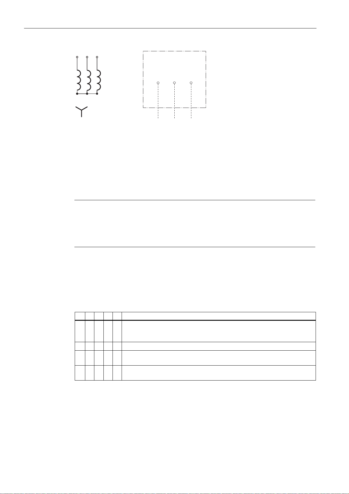
Figure 3-2 Connecting direction UVW for connection voltages of 400 V/480 V............................................28
Figure 3-3 Tightening torques for contact nuts and mounting bolts ① contact nut ② mounting bolt...........30
Figure 3-4 Detailed view of fan for operation at 50 Hz..................................................................................33
Figure 3-5 Fan for operation at 60 Hz ...........................................................................................................33
Figure 3-6 Detailed view: Plug-in connection................................................................................................34
Figure 3-7 Electrical connection of the speed sensor ...................................................................................35
Figure 3-8 Sensor Module ① mounted on terminal box ...............................................................................36
Figure 7-1 D-end and N-end end shields with grease nipples ......................................................................53
Figure 7-2 Detailed view of the speed sensor...............................................................................................59
Figure 7-3 Disassembling the speed sensor: forcing off, 1st option .............................................................60
Figure 7-4 Disassembling the speed sensor: forcing off, 2nd option ............................................................61
Figure 8-1 Spare parts 1PL6 .........................................................................................................................66
ESD protective measures ............................................................................................................10
A5E00215731A AD
Siemens AG Operating Instructions 2.02 1PL618
5
Page 8

Page 9
Safety information
1.1 Observing the five safety rules
For your personal safety and to prevent material damage when working on the device,
always observe the safety instructions on the product and the following five safety rules: You
must read the information provided in "Safety information".
The five safety rules:
1. isolate,
2. Protect against reconnection,
3. verify that the equipment is not live,
4. Ground and short circuit,
5. Cover or enclose adjacent components that are still live
Qualified personnel
Commissioning and operation of this machine are to be carried out by qualified personnel
only. For the purpose of the safety information in this Instruction Manual, a “qualified person”
is someone who is authorized to energize, ground, and tag equipment, systems, and circuits
in accordance with established safety procedures.
1
1.2 Safety and application instructions
The safe use of electrical machines
WARNING
Rotating or live parts
Rotating or live parts are dangerous.
Fatal or severe injuries and substantial material damage can occur if the required covers
are removed or if the machines are not handled, operated, or maintained properly.
Only remove covers in accordance with regulations and operate machines correctly.
Perform regular maintenance on the machine.
A5E00215731A AD
Siemens AG Operating Instructions 2.02 1PL618
7
Page 10

Safety information
1.2 Safety and application instructions
Qualified personnel
These operating instructions only contain the information that is necessary for the machines
to be used by qualified personnel in accordance with their intended purpose.
Those responsible for plant safety must ensure the following:
● The basic planning work for the system and all work relating to transportation, assembly,
installation, commissioning, maintenance and repairs is carried out by qualified personnel
and checked by responsible, suitably skilled personnel.
● The operating instructions and machine documentation are always available.
● The technical data and specifications relating to installation, connection, ambient and
operating conditions are taken into account at all times.
● The system-specific installation and safety regulations are observed.
● Personal protective equipment is used.
● Work on or in the vicinity of these machines by unqualified persons is prohibited.
● If the machines are used outside industrial areas, the installation site must be
safeguarded against unauthorized access by means of suitable protection facilities (e.g.,
safety gates) and appropriate warning signs.
See also
These operating instructions therefore only contain the information which is necessary for
the machines to be used by qualified persons in accordance with their intended purpose.
Note
Siemens Service Center
We recommend engaging the support and services of your local Siemens Service Center for
all planning, installation, commissioning, and maintenance work.
[ID 2.02]
Siemens Service Center (Page 15)
A5E00215731A AD
8 Siemens AG Operating Instructions 2.02 1PL618
Page 11
Safety information
1.3 Electromagnetic fields
1.3 Electromagnetic fields
Safety information
WARNING
Electromagnetic fields "electro smog"
Electromagnetic fields are generated by the operation of electrical power engineering
installations such as transformers, converters or motors.
Electromagnetic fields can interfere with electronic devices, which could cause them to
malfunction. For example, the operation of heart pacemakers can be impaired, potentially
leading to damage to a person's health or even death. It is therefore forbidden for persons
with heart pacemakers to enter these areas.
The plant operator is responsible for taking appropriate measures (labels and hazard
warnings) to adequately protect operating personnel and others against any possible risk.
● Observe the relevant nationally applicable health and safety regulations. In Germany,
"electromagnetic fields" are subject to regulations BGV B11 and BGR B11 stipulated by
the German statutory industrial accident insurance institution.
● Display adequate hazard warning notices.
● Place barriers around hazardous areas.
● Take measures, e.g. using shields, to reduce electromagnetic fields at their source.
● Make sure that personnel are wearing the appropriate protective gear.
[ID5003.011]
A5E00215731A AD
Siemens AG Operating Instructions 2.02 1PL618
9
Page 12
Safety information
1.4 ESD-sensitive components
1.4 ESD-sensitive components
ESD guidelines
CAUTION
Electrostatic discharge
Electronic modules contain components that can be destroyed by electrostatic discharge.
These modules can be easily destroyed by improper handling.
To protect your equipment against damage, follow the instructions given below.
● Never touch electronic modules unless absolutely necessary in the course of
maintenance and repair procedures.
● If the modules have to be touched, the body of the person concerned must be
electrostatically discharged immediately beforehand and be grounded.
● Electronic modules should not be brought into contact with electrically insulating materials
such as plastic foil, plastic parts, insulating table supports or clothing made of synthetic
fibers.
● Always place electrostatic endangered assemblies on conductive bases.
● Always store and transport electronic modules or components in conductive packaging
(e.g. metallized plastic or metal containers).
Note
If the modules are to be stored and/or transported in non-conducting packings anyway,
they must be wrapped in conducting materials before doing so. Always use suitable
material for this purpose, for example, conductive foam rubber or household aluminum
foil.
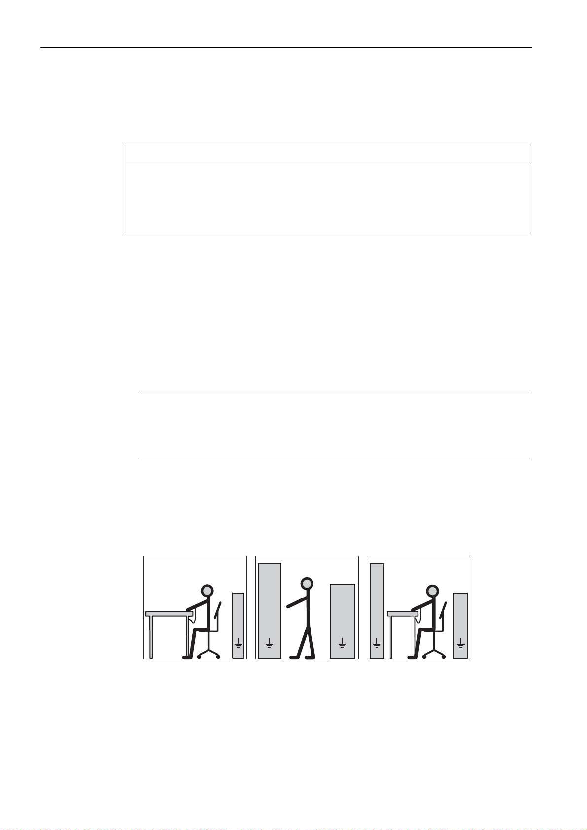
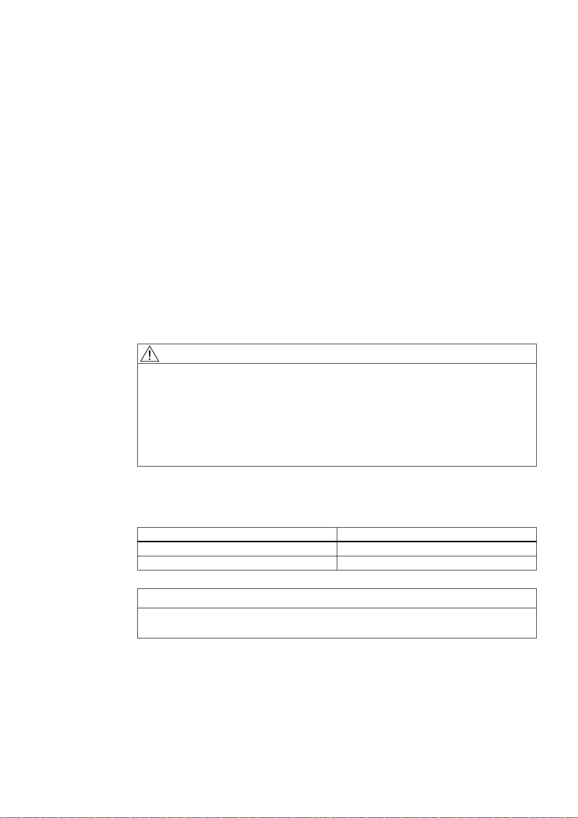
The necessary ESD protective measures for electrostatically sensitive devices are illustrated
once again in the following drawings:
b
cc c
(1) (2) (3)
Figure 1-1 ESD protective measures
A5E00215731A AD
d
ee
ff f f
aaaa
dd
b
e
f
10 Siemens AG Operating Instructions 2.02 1PL618
Page 13

Safety information
1.4 ESD-sensitive components
(1) Sitting
(2) Standing
(3) Standing/sitting
ESD protective measures
a = conductive floor
b = ESD table
c = ESD footwear
d = ESD coat
e = ESD wrist strap
f = cubicle ground connection
[ID 6006.01]
A5E00215731A AD
Siemens AG Operating Instructions 2.02 1PL618
11
Page 14
Safety information
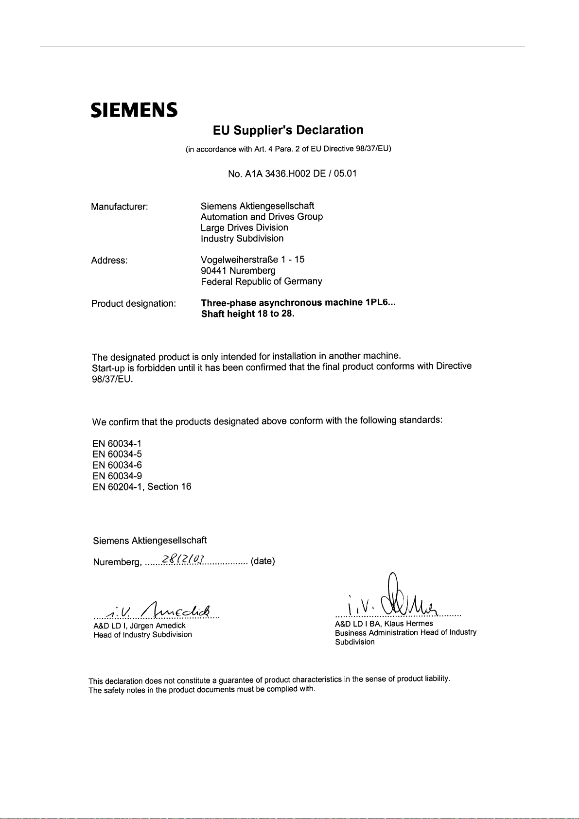
1.5 EC Declaration by the Manufacturer
1.5 EC Declaration by the Manufacturer
A5E00215731A AD
12 Siemens AG Operating Instructions 2.02 1PL618
Page 15
Safety information
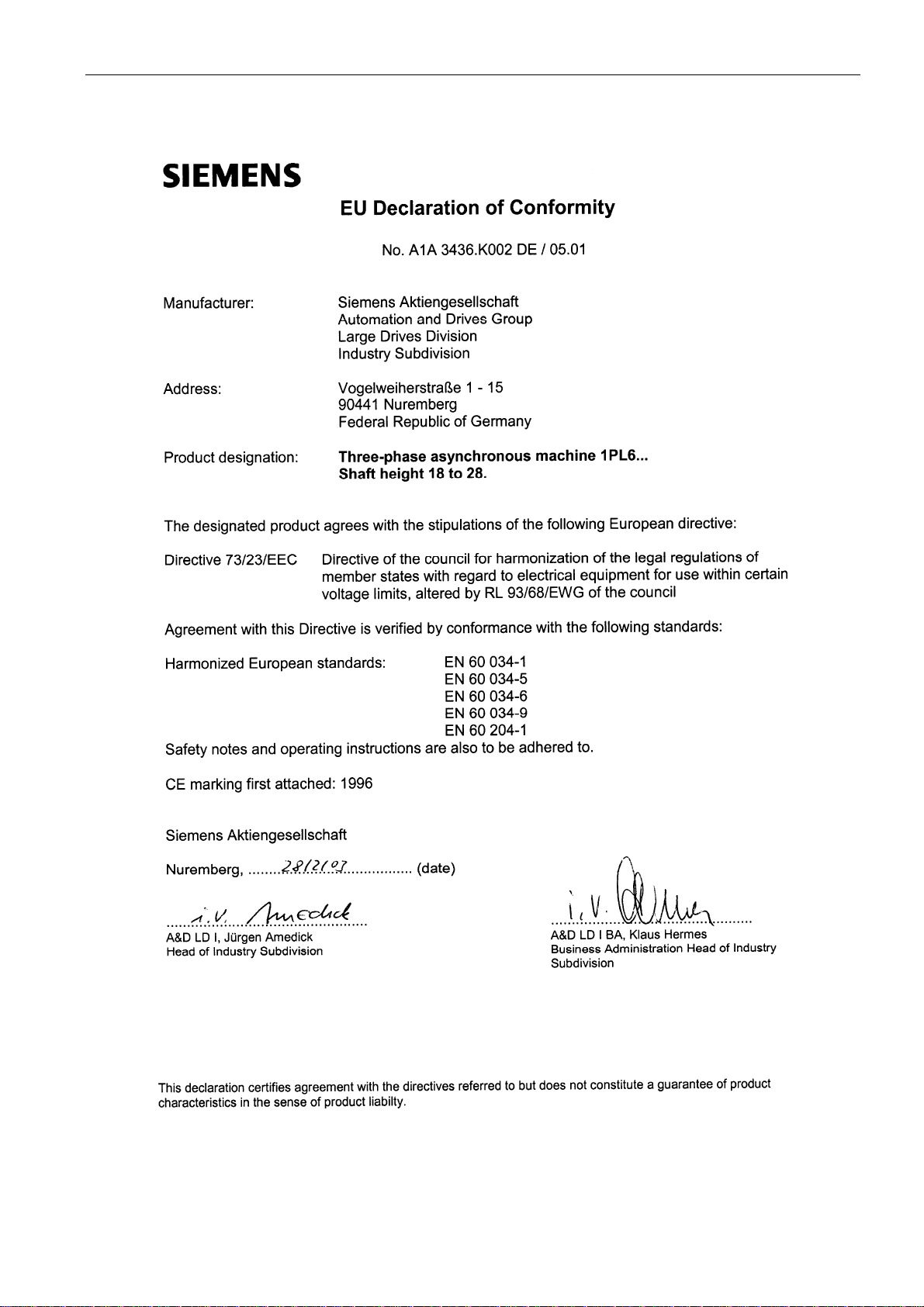
1.6 EC Declaration of Conformity
1.6 EC Declaration of Conformity
A5E00215731A AD
Siemens AG Operating Instructions 2.02 1PL618
13
Page 16

Page 17

Description
2.1 Applications
Overview
Three-phase motors of the 1PL6 series are used as industrial drives. They have been
designed for a wide range of applications in the fields of drive engineering and power
conversion.
They are characterized by their high power density, ruggedness, long lifetime, and overall
reliability.
[ID: 301]
2.2 Siemens Service Center
Contact for further information
Details regarding the design of this electrical machine and the permissible operating
conditions are described in these operating instructions. If you have any questions or
suggestions, or if you require additional information, please contact the Siemens Service
Center:
2
Table 2-1 Technical support
Europe - Germany:
America - USA: Phone: +1 423 262 2522
Asia - China: Phone: +86 1064 719 990
E-Mail: support.automation@siemens.com
Internet English: www.siemens.com/automation/support-request
Internet Deutsch: www.siemens.de/automation/support-request
A5E00215731A AD
Siemens AG Operating Instructions 2.02 1PL618
Phone: +49 (0)180 - 50 50 222
Fax +49 (0)180 - 50 50 223
15
Page 18
Description
0$'(,1*(50$1<'1íUQEHUJ
SIEMENS
2.3 Scope of delivery
2.3 Scope of delivery
Checking the scope of delivery for completeness
The drive systems are put together on an individual basis. When you take receipt of the
delivery, please check immediately whether the scope of the delivery matches up with the
accompanying documents. Siemens will not accept any claims relating to items missing from
the delivery and that are submitted at a later date.
● Report any apparent transport damage to the delivery agent immediately.
● Report any apparent defects/missing components to the appropriate SIEMENS office
immediately.
These Operating Instructions are included in the scope of delivery and must be kept in a
location where they can be easily accessed.
The rating plate enclosed as a loose item with the delivery ensures that the motor data can
also be affixed on or near the machine or system.
[ID: 303.02]
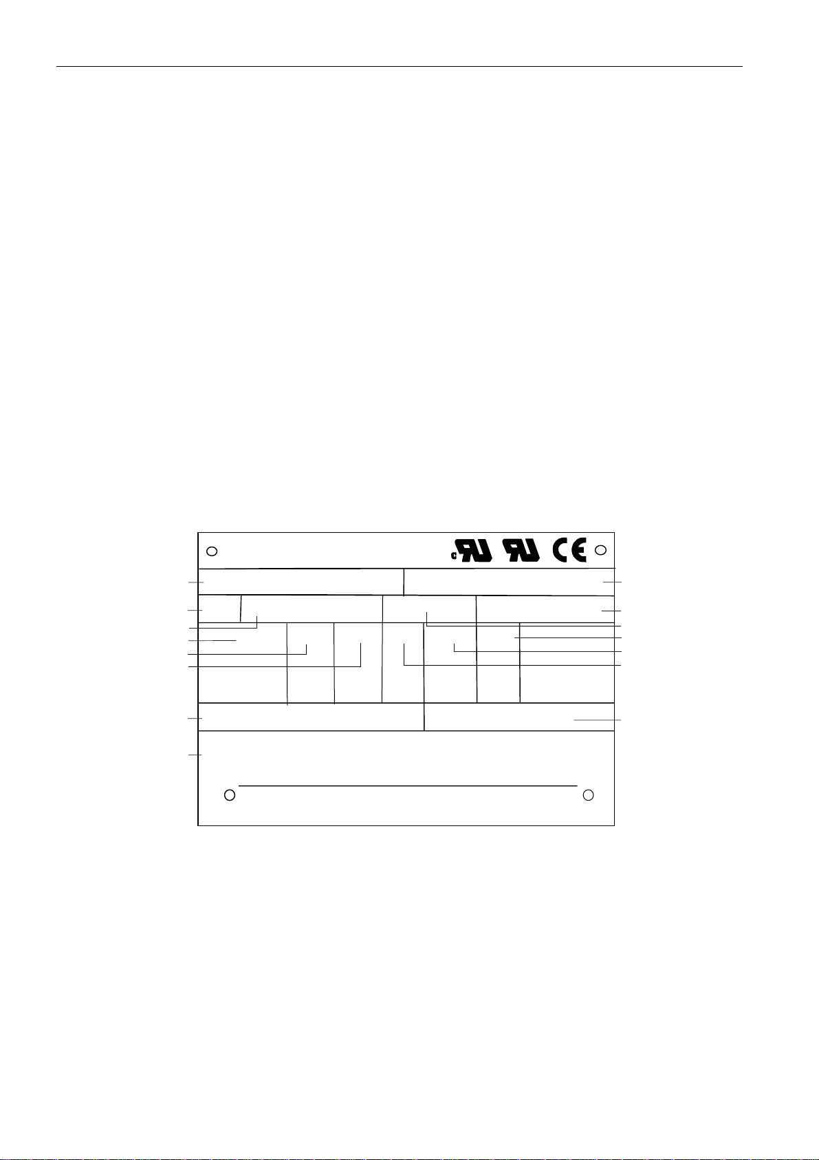
2.4 Rating plate
The motor rating plate shows the technical specifications applicable to the supplied motor.
a0RW
ແ
ໂ
%
ໃ
ໄ
ໆ
(1(&
.7<
່
(1&2'(5B+BB65
Figure 2-1 Example - 1PL6 motor rating plate
Table 2-2 Motor rating plate – technical specifications
1 Motor type: Three-phase induction motor
2 Type of construction
3 Degree of protection
4 Rated voltage [V] and winding connection
5 Rated current [A]
3/+'$& 1R17
9
<
<
<
,3,0
$
7K&O
N: FRV
)
+] PLQ
PD[
*HZ:7 NJ
0$'(,1*(50$1<'1íUQEHUJ
PLQ
້
໊
໋
໌
ໍ
໎
'(:
A5E00215731A AD
16 Siemens AG Operating Instructions 2.02 1PL618
Page 19
Description
2.5 Layout
6 Rated output [kW]
7 Standards and regulations
8 Code sensor type, temperature sensor KTY84
9 Serial number
10 Motor weight [kg]
11 Temperature class
12 Rated speed [rpm]
13 Rated frequency [Hz]
14 Power factor [cos φ]
15 Maximum speed [rpm]
[ID: 307.02]
2.5 Layout
2.5.1 Cooling
Description
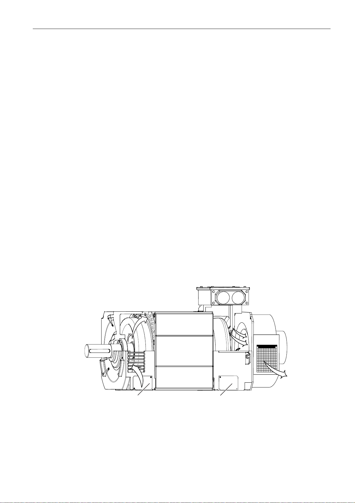
The three-phase motors of the 1PL6 series are externally and enclosed-ventilated, lowvoltage induction motors with a squirrel-cage rotor and a separately driven fan unit mounted
as standard. The motors have an internal cooling circuit (cooling method IC06 according to
DIN EN IEC 60034-6).
Cooling process (basic type)
Figure 2-2 Cooling process for ventilating from the drive end to the non-drive end (basic type)
A5E00215731A AD
Siemens AG Operating Instructions 2.02 1PL618
ཱ
17
Page 20

Description
2.5 Layout
① Cover sheet
② Cooling flow
A KTY 84 temperature sensor is installed in the stator winding to monitor the winding.
Depending on the order, various additional devices such as sensor systems can be installed
or built on.
NOTICE
A minimum clearance of 100 mm from devices added on by the customer must be
observed at the air intake opening and at the air outlet openings, in order to guarantee the
necessary flow of cooling air.
Securing the cooling capacity
CAUTION
Missing cover sheets can result in considerably reduced cooling capacity and thus cause
an inadmissible temperature rise within the motor.
Please ensure that the cover sheets are always mounted.
[ID: 973.00]
2.5.2 Drive
Description
The variable-speed, three-phase motors of the 1PL6 series are supplied with power by a
frequency converter.
[ID: 313]
2.5.3 Construction types
Further potential applications
The construction type of the motor is stated on the rating plate.
CAUTION
During transportation, motors must only be hoisted in a position corresponding to their
basic construction type.
A5E00215731A AD
18 Siemens AG Operating Instructions 2.02 1PL618
Page 21
Description
2.5 Layout
Basic construction type acc.
to rating plate
IM B3 1PL6 184…1PL6 186 IM B6, IM B7, IM B8, IM V5, IM V6
IM B35 (1) 1PL6 184…1PL6 186 IM V36, IM V15
The maximum permissible speed for flange-mounted construction types (IM B5, IM V1, IM
V3) is restricted to 3000 rpm (see also "Planning Guide").
Type Other applications in construction type
Note
For additional instructions and restrictions for construction types that do not correspond to
the basic type, please refer to the "Planning Guide".
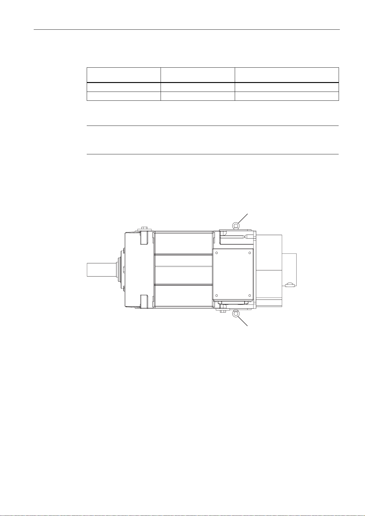
Additional hoisting points for different construction types (option)
Additional hoisting points are provided for those construction types that differ from the basic
construction types IM B3 and IM B35 (see Fig.).
ແ
Figure 2-3 View from above onto construction type IM B3
① Hoisting points
[ID: 318.01]
2.5.4 Regulations
Overview
The motors comply with the following regulations under IEC EN 60034:
A5E00215731A AD
Siemens AG Operating Instructions 2.02 1PL618
ແ
19
Page 22

Description
2.5 Layout
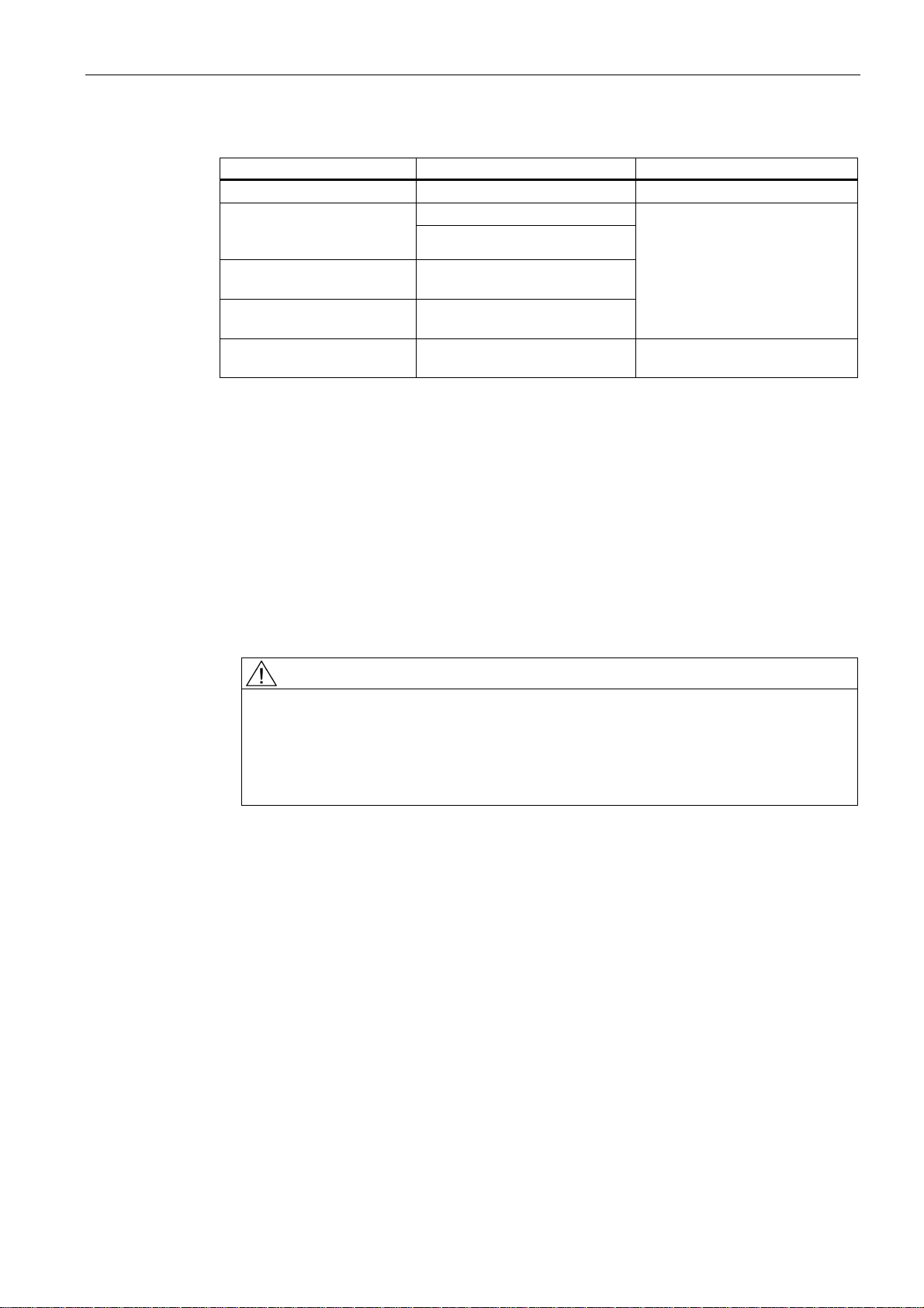
Table 2-3 Compliance with standards
Feature Standard
Dimensions and operating performance IEC/EN 60034-1
Degree of protection (1) IEC/EN 60034-5
Cooling IEC/EN 60034-6
Type of construction IEC/EN 60034-7
Noise emission IEC/EN 60034-9
Vibration severity levels IEC/EN 60034-14
(1) See the rating plate for the degree of machine protection.
[ID: 319.01]
2.5.5 Degree of protection
The three-phase motors of the 1PL6 series are built to degree of protection IP23 in
accordance with IEC EN 60034-5.
The standard version of the motors is not suitable for operation in a salt-laden or corrosive
atmosphere, nor for installation outdoors.
[ID: 391]
A5E00215731A AD
20 Siemens AG Operating Instructions 2.02 1PL618
Page 23
Transport, assembly, and connection
3.1 Transport, storage, and maintenance
3.1.1 Transport, storage
Instructions relevant to safety
Please observe the following instructions on the transportation and storage of motors.
WARNING
Motors may only be attached to and hoisted by the main eyebolts that are located at the
end shields. Auxiliary eyebolts, e.g. on fan cowls and cooler attachments, are suitable only
for hoisting the respective parts.
To hoist the motor, in particular at attachments and built-on assemblies, use suitable cableguidance or spreading equipment.
Observe the lifting capacity of the hoisting gear.
3
(For weight, see rating plate and table "Weights of standard versions")
Table 3-1 Weights of standard versions (IM B3)
Type Weight
1PL6 184 Approx. 370 kg
1PL6 186 Approx. 440 kg
NOTICE
If the motor is not immediately commissioned, then it should be stored in a dry room which
is free from vibration and shock.
A5E00215731A AD
Siemens AG Operating Instructions 2.02 1PL618
21
Page 24

Transport, assembly, and connection
3.1 Transport, storage, and maintenance
Transporting motors with a rotor shipping brace
Motors with cylindrical-roller bearings have a rotor shipping brace (shaft block), in order to
prevent the bearings from becoming damaged during transportation/shipping.
● Only remove this brace before fitting the drive element.
[ID: 325.01]
3.1.2 Storage
CAUTION
Seizure damage to friction bearings and rolling-contact bearings
If storage conditions are inappropriate there is a risk of bearing seizure damage. This can
result in brinelling, for example.
Read the following notes on storage.
Storing outdoors
Store the machine in a location that meets the following criteria:
NOTICE
Take other suitable measures to axially fix the rotor if the motor has to be transported
after you have fitted the drive element.
Storing indoors
● Choose a dry storage location with plenty of space, which is safe from flooding and free
from vibrations.
● Repair any damage to the packaging before putting the equipment into storage insofar as
this is necessary to ensure proper storage conditions.
● Position machines, devices, and crates on pallets, wooden beams or foundations that
guarantee protection against ground dampness.
● Prevent the machine sinking into the ground.
● Ensure that the air circulation under the equipment is not impeded.
– Covers or tarpaulins used to protect the equipment against the weather must not
make contact with the surfaces of the equipment.
– Covers or tarpaulins must not trail on the floor around the machine.
– Place wooden spacer blocks between the covers and the machine.
● Store the machine in a room that meets the following criteria:
– Dry, dust-free, frost-free and vibration-free
– Well ventilated
A5E00215731A AD
22 Siemens AG Operating Instructions 2.02 1PL618
Page 25

Transport, assembly, and connection
3.1 Transport, storage, and maintenance
– Offers protection against extreme weather conditions
– The air in the room must not contain any harmful gases.
● Protect the machine from shocks and humidity.
[ID 1079.01xx]
3.1.3 Preservation
Preservation
If you are storing a machine for more than six months, you must check its condition every six
months.
● Check the machine for damage.
● Carry out any necessary maintenance work.
● Document all preservation measures taken so that they can be reversed before the
machines are put back into service.
● Provide a constant source of low heat to the machine windings, along with forced air
Condensation water
Condensation water can collect in the machine as a result of sharp fluctuations in ambient
temperature, exposure to direct sunlight, high levels of humidity in the storage location or
intermittent operation/variations in load during operation.
CAUTION
Damage caused by condensation water
If the stator winding gets damp, its insulation resistance decreases. This results in voltage
flashovers, which can destroy the winding. Condensation can also cause rusting inside the
machine.
ventilation.
CAUTION
Bearing damage caused by vibrations
If storage conditions are inappropriate there is a risk of bearing seizure damage. This
can result in material damage, such as damage to bearings due to vibration.
On machines that have been supplied with a rotor locking device, secure the rotor as
per the notes on transportation. Protect the machine against strong radial vibrations,
since the rotor locking device might not absorb these completely.
Ensure that condensation water is drained off.
In the end shields at the drive end and non-drive end, water drain holes are situated in the
foot area and opposite the regreasing devices. They are sealed with small plastic plugs or
screw plugs. Depending on the type of installation, the water drain holes are located at the
bottom.
A5E00215731A AD
Siemens AG Operating Instructions 2.02 1PL618
23
Page 26

Transport, assembly, and connection
3.2 Assembly
1. Remove the screw plugs or plastic plugs regularly to drain off the condensation water.
2. Replace the plugs afterwards.
NOTICE
Degree of protection
Nominally the degree of protection of the machine is reduced to IP44 by removing the
plastic plug or screw plug.
[ID 1079.02]
3.2 Assembly
3.2.1 Installation
Instructions relevant to safety
CAUTION
The enclosure components of electric motors can become very hot (possibly > 100 °C). Do
not touch enclosure components while the motor is running or immediately after it has been
running.
CAUTION
When positioning temperature-sensitive components (wires etc.), make sure that they are
not in contact with the motor enclosure.
NOTICE
Note also the technical specifications on the rating plates on the motor enclosure.
Cooling conditions in general
● In the case of motors that are cooled by the ambient air, the cooling air must be able to
flow unimpeded to and from the motors. Hot discharged air must not be reinducted (see
also "Cooling").
Cooling conditions for motors with pipe connection
Motors that are configured to allow pipes to be connected and/or for operation with a
separately driven fan must have pipes and a fan of suitable type and dimensioning mounted
and connected to them.
A5E00215731A AD
24 Siemens AG Operating Instructions 2.02 1PL618
Page 27
Transport, assembly, and connection
3.2 Assembly
Please refer to the table below for the potential pressure drop inside the motor for motors
with a pipe connection:
Table 3-2 Pressure drop in motors with pipe connection
1PL6 18.
Volumetric flow (V) Pressure drop (Δp)
0.27 m3/s 650 Pa
Balancing quality
NOTICE
Please consider the additional pressure drop that arises in the system when connecting the
pipes.
Also ensure that:
● you comply with the conditions of the IP degree of protection.
Higher IP requirements may necessitate the installation of suitable filters and special
positioning of the intake and outlet openings.
● units and wires are mounted without distortion.
● the shipping covers of the ventilation openings are removed.
The rotors are balanced dynamically. In the case of shaft ends with feather keys, the method
used to balance the rotors can be identified from the following coding to be found on the end
face at the drive end of the shaft end:
● Code "H" means balancing with half a feather key (standard version); this means that in
order to maintain the balancing quality it may be necessary to cut back the part of the
feather key protruding from the drive element and the shaft profile if the motor has a short
output element.
● "F" means balancing with a whole featherkey (optional version).
Make sure that the balancing method of the output element is correct!
CAUTION
A suitable tool must always be used for fitting and pulling off output elements.
The feather keys are only locked against falling out during shipping.
Noise emission
Motors of the 1PL618. series have a measuring surface sound pressure level Lp(A) of
approx. 73 dB(A) + 3 dB (tolerance) in a speed range from 0 through 2000 rpm.
A5E00215731A AD
Siemens AG Operating Instructions 2.02 1PL618
25
Page 28

Transport, assembly, and connection
3.2 Assembly
The motors are certified for a wide range of installation and operating conditions. In some
cases, these conditions (e.g. rigid or vibration-isolated foundation design, use of soundabsorbing elements) can have a significant influence on noise emissions.
When evaluating the noise levels at the workplaces of the system operators, consider the
fact that the A-weighted sound pressure level (measured in accordance with DIN EN 21680
Tl.1) of 70 dB(A) is exceeded when the three-phase motors are operated at nominal load.
[ID: 329.01]
3.2.2 Mounting
Requirements
In order to ensure smooth, vibration-free motor operation, a stable foundation design is
required, the motor must be precisely aligned, and the components that are to be mounted
on the shaft end must be correctly balanced.
Removing the cover sheets
Cover sheets are attached by means of the screw positions on the motor feet.
The cover sheets (1) have to be removed before mounting the motor
Figure 3-1 (1) Cover sheet (detailed view)
CAUTION
The cover sheets ensure the cooling of the motor.
Please make sure that the cover sheets are always screwed back onto the motor after
mounting the motor via the motor feet.
ແ
Fixing by means of motor feet
If the motor needs to be aligned, position metal shims underneath the feet in order to prevent
machine deformation.
The number of shims should be kept as low as possible i.e. stack as few as possible.
A5E00215731A AD
26 Siemens AG Operating Instructions 2.02 1PL618
Page 29

Transport, assembly, and connection
3.3 Electrical connection
Fixing bolts
To securely mount the motor and reliably transfer the drive torque, use motor fixing bolts
(M12) with the required strength class (8.8) in accordance with ISO 898-1.
NOTICE
All flange motors must have stable suspension and be supported by means of the endshield feet (foot-flange type of construction). When carrying out commissioning, make sure
that the vibration values permitted in accordance with DIN ISO 10816-3 are maintained.
Motors that are mounted, as a result of their type of construction, to the wall using the
motor feet, must be fixed in place using an adequately dimensioned positive form fit (e.g.
using studs or mounting rails).
[ID: 331.02]
3.3 Electrical connection
3.3.1 Safety note for the drive-CLIQ interface
CAUTION
Electrostatically sensitive devices
The drive-CLIQ interface contains components that are susceptible to electrostatic
charging. DTouching connections on the sensor module with electrostatic charged hands or
tools can cause malfunctions.
Comply with ESD protection measures (Page 10).
[ID 962.01]
3.3.2 Connecting the stator winding
Circuit diagram
Details with respect to wiring and connecting the motor winding are laid down in the circuit
diagram. The circuit diagram is attached to the lid of the terminal box.
A5E00215731A AD
Siemens AG Operating Instructions 2.02 1PL618
27
Page 30
Transport, assembly, and connection
$
3.3 Electrical connection
'
:
$':
Figure 3-2 Connecting direction UVW for connection voltages of 400 V/480 V
Select the connecting cables taking into account the rated current and the system specific
conditions (e.g. ambient temperature, routing type etc. in accordance with IEC EN 60204-1).
Direction of rotation
Connection of the power cables in the phase sequence L1, L2, L3 to U, V, W results in
clockwise rotation. If two of the connections are swapped then the resulting direction of
rotation is counter-clockwise (e.g. L1, L2, L3 to V, U, W).
Note
These restrictions in terms of the direction of rotation relate to the particular type of motor
design and result, for example, from the use of unidirectional fans. Any restrictions in terms
of the direction of rotation resulting from the installation itself are not shown in the
information on the rating plate and need to be considered separately when making the
connections.
Terminal designations
The following definitions apply in principle to the terminal designations of three-phase motors
in accordance with DIN VDE 0530 Part 8 or IEC 60034-8:
&LUFXLW
Table 3-3 Terminal designations (with the 1U1-1 as an example)
1 U 1 - 1 Identifier
x Index showing the pole assignment for pole-changing motors (where applicable,
a lower number indicates a lower speed) or, in special cases, for a subdivided
winding
x Phase designation (U, V, W)
x Index showing the start (1) / end (2) or tapping point of the winding (if there is
more than one connection per winding)
x Additional index for cases in which it is obligatory to connect parallel power feed
cables to several terminals with otherwise identical designations
Connecting using cable lugs
To connect the cables to the main terminals, select cable lugs that match the necessary
cable cross-section and bolt size M12.
A5E00215731A AD
28 Siemens AG Operating Instructions 2.02 1PL618
Page 31

Transport, assembly, and connection
3.3 Electrical connection
Table 3-4 Terminal box assignment, max. connectable cross-section per terminal
Motor type Terminal
box type
8. th digit of the MLFB = 4, 6
1PL6 184-..B
1PL6184-..D
1PL6184-..F
1PL6184-..L 1XB7 422 2 x M72 x 2 56 3 x M12 2 x 70 242
1PL6186-..B
1PL6186.-..D
1PL6186-..F 1XB7 422 2 x M72 x 2 56 3 x M12 2 x 70 242
1PL6186-..L 1XB7 700 3 x M72 x 2 56 3 x 2 x M12 3 x 150 583
8. th digit of the MLFB = 7, 8
1PL6 184-..B
1PL6184-..D
1PL6184-..F
1PL6184-..L 1XB7 422 2 x M63 x 1.5 53 3 x M12 2 x 70 242
1PL6186-..B
1PL6186-..D
1PL6186-..F 1XB7 422 2 x M63 x 1.5 53 3 x M12 2 x 70 242
1PL6186-..L 1XB7 700 3 x M75 x 1.5 68 3 x 2 x M12 3 x 150 583
1XB7 322 2 x PG 42 40 3 x M12 2 x 50 191
1XB7 322 2 x PG 42 40 3 x M12 2 x 50 191
1XB7 322 2 x M50 x 1.5 38 3 x M12 2 x 50 191
1XB7 322 2 x M50 x 1.5 38 3 x M12 2 x 50 191
Cable entry Max. poss.
outer
diameter of
cable [mm]
No. of main
terminals
Max.
connectable
cross-section
per terminal
2
[mm
]
Max. poss. current per
terminal [A]
(Reduction factor 0.6)
Remove the insulation from the conductor ends so that the remaining insulation is almost
long enough to reach the cable lug.
If necessary, insulate the cable lugs in order to maintain the minimum clearances in air of 10
mm and the 20 mm creepage distance normally present.
The tightening torque for M12 contact nuts and mounting bolts is 40 Nm.
A5E00215731A AD
Siemens AG Operating Instructions 2.02 1PL618
29
Page 32

Transport, assembly, and connection
3.3 Electrical connection
1P
Figure 3-3 Tightening torques for contact nuts and mounting bolts
① contact nut
② mounting bolt
Principles of fitting and laying cables
Lead in permanently laid entries using EMC cable glands. Screw the cable glands into the
threaded holes in the entry plate, which can be unscrewed.
Arrange the exposed connecting cables in the terminal box such that the PE conductor has
excess length and the insulation of the cable strands cannot be damaged.
Note
We recommend you use shielded cables whose shields are conductively connected to a
large area of the metal terminal box of the motor (with an EMC cable gland made of metal).
NOTICE
Unused threads must be sealed with a metallic screw plug.
Internal equipotential bonding
The equipotential bonding between the ground terminal in the terminal box housing and the
motor frame is established via the terminal box mounting bolts. The contact points
underneath the bolt heads are bare metal and are protected against corrosion.
The standard terminal box cover mounting screws are adequate as potential bonding
between the terminal box cover and terminal box itself.
Final checks
Before closing the terminal box, please check that:
A5E00215731A AD
30 Siemens AG Operating Instructions 2.02 1PL618
Page 33

Transport, assembly, and connection
3.3 Electrical connection
● the electrical connections in the terminal box are tight and are in full compliance with the
specifications above.
● the required clearances in air of 10 mm are maintained.
● no wire ends are standing proud.
● The inside of the terminal box must be clean and free of any pieces of cable.
● all seals and sealing surfaces are not damaged.
● the connecting cables are laid in an open arrangement and the cable insulation cannot be
damaged.
● cable entries which are not used are sealed and the plugs are tightly screwed in (i.e. so
that they can only be removed using the suitable tools).
● the right cable glands are fitted with respect to the correct degree of protection, method of
laying, permissible cable diameter etc., as stated in the specifications.
Then close the terminal box.
Table 3-5 Tightening torque for the fixing screws on the lid
Bolt Terminal box type Tightening torque
M6 1XB7 322 4.5 Nm
M8 1XB7 422 11 Nm
M10 1XB7 700 22 Nm
[ID: 335.01]
3.3.3 Connecting the ground conductor
General
The cross-section of the ground conductor of the motor must comply with the regulations for
electrical installations, e.g. DIN EN IEC 60204-1.
Wiring
Connect-up the ground-conductor in the motor terminal box. For this purpose, a clamping lug
is provided at the appropriately marked connecting point for the ground conductor This lug
can be used for connecting stranded conductors with cable lugs or ribbon cables with an
appropriately shaped conductor end.
When making connections, ensure that
● The contact surface is clean and protected with a suitable anti-corrosion agent (e.g. acidfree Vaseline).
● the flat and spring washers are located under the bolt head.
● the minimum necessary screw-in depth and the tightening torque for the clamping bolts
must be maintained.
Mandatory tightening torques:
A5E00215731A AD
Siemens AG Operating Instructions 2.02 1PL618
31
Page 34

Transport, assembly, and connection
3.3 Electrical connection
Bolt Terminal box type Tightening torque
M5 1XB7 322 2.6 Nm
1XB7 422 11 Nm M8
1XB7 700 11 Nm
[ID: 354]
3.3.4 Connecting the fan
Instructions relevant to safety
Please observe the following safety instructions relating to connecting a fan:
Connection
CAUTION
Provide a protective circuit that prevents the main motor from being switched on when the
fan unit is not in operation.
CAUTION
Please note that the separately driven fan unit is only suitable for the direction of rotation
shown by the direction-of-rotation arrow.
The fan must not be operated with the wrong direction of rotation as this could lead to the
motor being destroyed.
Note
The direction-of-rotation arrow and the direction of movement of the fan impeller are
indicated on the rear side of the blower.
If necessary, switch the direction of rotation by swapping over two phase conductors in the
terminal box.
Connect up the fan in the terminal box of the fan unit.
A5E00215731A AD
32 Siemens AG Operating Instructions 2.02 1PL618
Page 35

Transport, assembly, and connection
3.3 Electrical connection
ུ
ི
ཱ
ཱི
Figure 3-4 Detailed view of fan for operation at 50 Hz
① Fan unit terminal box
② Cable entry
③ Direction of rotation of fan impeller
④ Air outlet grille
⑤ Air outlet throttle sheet fixing points
CAUTION
If the standard fan is operated with ventilation from the DE to the NDE on a 60 Hz system,
you must screw on the air outlet throttle sheet included in the terminal box.
ིུ
ཱ
ཱུ
ཱི
Figure 3-5 Fan for operation at 60 Hz
① Fan unit terminal box
② Cable entry
③ Direction of rotation of fan impeller
④ Air outlet grille
⑤ Air outlet throttle sheet fixing points
⑥ Throttle sheet
A5E00215731A AD
Siemens AG Operating Instructions 2.02 1PL618
33
Page 36

Transport, assembly, and connection
3.3 Electrical connection
[ID: 338.01]
3.3.5 Connecting the speed sensor
Connection
Connect the speed sensor to the terminal box by means of a plug-in connection ①. It is
located on top of the box housing.
Figure 3-6 Detailed view: Plug-in connection
Note
The plug-in connection may differ from the standard layout in the case of special orders.
In the version "without sensor", an armored conduit union is located here.
A5E00215731A AD
34 Siemens AG Operating Instructions 2.02 1PL618
Page 37

Transport, assembly, and connection
3.3 Electrical connection
Electrical connection of the speed sensor
ཱ
Figure 3-7 Electrical connection of the speed sensor
ི
① Insert the connector into the socket.
② Press the cable into the holder provided for it.
③ Screw on the sensor cover. Take care that you do not catch the cable as you screw it
in.
[ID: 977.00]
3.3.6 Connecting the Sensor Module
Signal connection
The signal connection between the motor and the converter is via the DRIVE-CLiQ cable
MOTION-CONNECT. Always use prefabricated cables from SIEMENS. Thes cables reduce
the mounting/installation time and costs and increase operational reliability.
Push the connector on the DRIVE-CLiQ cable into the socket until the catch spring latches
into place. Pay attention to the coding of the connector.
Cable outlet directions
The Sensor Module is mounted on the motor terminal box. The Sensor Module can be
rotated through approximately 235°. You can change the cable outlet directions by rotating
the Sensor Module, as shown in the diagram below.
A5E00215731A AD
Siemens AG Operating Instructions 2.02 1PL618
35
Page 38

Transport, assembly, and connection
S
3.3 Electrical connection
NOTICE
Do not turn the Sensor Module with a pipe wrench or hammer or any similar tool as this
could damage the Sensor Module.
Turn the Sensor Module by hand.
Typical twisting moment: 4 ... 8 Nm
¡
ແ
Figure 3-8 Sensor Module ① mounted on terminal box
NOTICE
Changing the cable outlet direction by any improper means will cause damage to the
connecting cables.
The permissible rotation range must not be exceeded. A maximum of ten changes to the
rotation angle of the Sensor Module are permissible within the rotation range.
[ID 964]
3.3.7 Connecting the temperature sensor
Connection
Connect the wires of the temperature sensor to the speed sensor connector with the aid of
connecting leads (see section entitled "Connecting the speed sensor").
A5E00215731A AD
36 Siemens AG Operating Instructions 2.02 1PL618
Page 39

Transport, assembly, and connection
3.3 Electrical connection
Note
The plug-in connection may differ from the standard layout in the case of special orders.
In the version "without sensor", an armored conduit union is located here.
[ID: 342]
A5E00215731A AD
Siemens AG Operating Instructions 2.02 1PL618
37
Page 40

Page 41

Start-up
4.1 Preparations
Safety note
Checking the insulation resistance
WARNING
Only expert personnel should be entrusted with work on power installations.
Note
There is no need to check the insulation resistance when commissioning. We only
recommend doing so after long storage or shutdown periods.
After long storage or shutdown periods, the insulation resistance of the windings must be
measured to ground with direct voltage.
WARNING
4
Hazardous voltage
During the measurement, and immediately afterwards, hazardous voltage levels are
applied on some of the terminals and they should not be touched. Touching live
components can be result in death or serious injury.
Never touch the terminals when measuring or immediately after the measurement.
Check the supply feeder cables connected in order to ensure that the line supply voltage
cannot be connected.
CAUTION
Before you begin measuring the insulation resistance, please read the manual for the
insulation resistance meter you are going to use.
● Always measure the insulation resistance of the winding to the motor enclosure when the
winding temperature is between 20 and 30°C.
A5E00215731A AD
Siemens AG Operating Instructions 2.02 1PL618
39
Page 42

Start-up
4.1 Preparations
● When measuring, wait until the final resistance value is reached; this takes approximately
one minute.
Stator winding insulation resistance limit values
The following table shows the measuring circuit voltage and the limit values for the minimum
insulation resistance and the critical insulation resistance for the stator winding.
Table 4-1 Stator winding insulation resistance at 25 °C
Rated voltage U
Measuring circuit voltage 500 V (min. 100 V)
Minimum insulation resistance with new, cleaned or
repaired windings
Critical specific insulation resistance after a long operating
time
10 MΩ
2.5 MΩ/kV
< 2 kV
N
Note the following:
● Dry, new windings have insulation resistance of between 100 and 2000 MΩ, or possibly
values that are even higher.
If the insulation resistance is close to the minimum value, then the cause could be
humidity and/or fouling.
● Over its operating lifetime, the motor winding insulation resistance can drop due to
ambient and operational influences. The critical insulation resistance at a winding
temperature of 25°C is 2.5 MΩ
NOTICE
Critical insulation resistance is reached or insufficient
If the critical insulation resistance is reached or is insufficient, damage to the insulation and
flashover voltages can result.
Dry the windings or clean and dry them thoroughly, having first removed the rotor.
If the clean windings have not cooled to 25°C, then lower insulation resistance will be
measured. The insulation resistance can only be properly assessed after conversion to the
reference temperature of 25°C. Allow the windings to cool to 25°C or convert the insulation
resistance using 25°C as the reference temperature.
If the measured value is close to the critical value, you must check the insulation resistance
at appropriately frequent intervals subsequently.
[ID: 344.01]
A5E00215731A AD
40 Siemens AG Operating Instructions 2.02 1PL618
Page 43

Start-up
4.2 Measures to be performed prior to commissioning
4.2 Measures to be performed prior to commissioning
Note
This list below does not claim to be complete. It may be necessary to perform additional
checks and tests in accordance with the situation specific to the particular place of
installation.
Inspections after proper installation, prior to commissioning the plant
● All electrical and mechanical connections are securely seated and functioning properly.
● The motor has been assembled and aligned properly.
● The cover sheets have been remounted correctly to ensure that the motor is cooled.
● The operating conditions correspond to the data specified on the rating plate.
● Any supplementary motor monitoring devices and equipment have been correctly
connected and are fully functional.
● Appropriately configured control and speed monitoring functions ensure that the motor
cannot exceed the permissible speeds specified on the rating plate.
● The power output elements have the proper setting conditions according to type, for
example.
– Couplings are aligned and balanced.
– The belt tension is properly adjusted if there is a belt drive.
– Gear tooth flank play and gear tooth tip play as well as radial play are properly
adjusted if there is gearwheel drive.
● The minimum insulation resistance values are maintained.
● The grounding and equipotential bonding connections have been established correctly.
● All fixing screws, connecting elements and electrical connections are firmly tightened.
● The rotor can spin without coming into contact with the stator.
● All touch protection measures for moving and live parts have been taken.
● if the second shaft end has not been used, its feather key has been secured to prevent it
from being thrown out.
● All external fans fitted are ready for operation and have been connected so that they
rotate in the direction specified.
● The flow of cooling air is not impeded.
● All brakes are operating correctly.
NOTICE
Lubricating capacity of lubricating greases
Grease loses its lubricating property over time.
After longer period of storage or standstill (> 2 years) lubricate the bearings or replace
the grease.
A5E00215731A AD
Siemens AG Operating Instructions 2.02 1PL618
41
Page 44

Start-up
4.3 Power on
[ID: 399.02]
4.3 Power on
Measures
Before you energize the motor, make sure that the parameters of the frequency converter
have been assigned correctly.
We recommend you use appropriate commissioning tools (e.g. Drive ES or STARTER).
CAUTION
If the motor is not running smoothly or is emitting abnormal noises, de-energize it, and
determine the cause of the fault as the motor runs down.
NOTICE
The critical speed n
periods.
= 5000 rpm is the maximum operating speed permissible over short
max
[ID: 369.01]
A5E00215731A AD
42 Siemens AG Operating Instructions 2.02 1PL618
Page 45

Operation
5.1 Operation
Safety notes
WARNING
Please follow all instructions contained in the "Safety information and application
information (Page 7)" chapter of these operating instructions precisely and ensure that only
persons who have the necessary specialist know-how are entrusted to carry out work on
power installations.
WARNING
Rotating components
Covers prevent contact with live or rotating parts, or are used for proper air routing and thus
effective cooling of the motor.
Removing the covers during operation can result in death, serious injury, and property
damage.
5
Never open covers during operation.
CAUTION
Speed monitoring
The motor is designed for a certain speed range.
If a motor is operated at impermissible speeds damage to the winding, bearings, or
complete destruction of the motor can be the result.
Ensure that the speeds specified on the rating plate are not exceeded by appropriately
configuring controller and speed monitoring components.
Switching on
● See the operating instructions of the frequency converter for switching on.
● After starting the motor, observe it for a while to see if it is running smoothly and check
the monitoring devices.
A5E00215731A AD
Siemens AG Operating Instructions 2.02 1PL618
43
Page 46

Operation
5.2 Stoppages
Operation
● Monitor operation and the monitoring devices regularly and record the values you read
off.
[ID: 348]
WARNING
Faults
All deviations from normal operation, such as higher power consumption, higher
temperatures and vibration levels, unusual noises and odors and tripped monitoring
devices, are indications that the motor is no longer functioning correctly.
In this case, the maintenance technician must be notified immediately to prevent
disturbances that could either directly or indirectly lead to severe personal injury or
substantial material damage.
If in doubt, switch off the drive in question immediately.
See also
Rating plate (Page 16)
Power on (Page 42)
5.2 Stoppages
Measures when motors are at standstill and ready for operation
● For longer periods when the motor is not being used, either energize the motor at regular
intervals (roughly once a month), or at least spin the rotor.
● Please refer to the section "Energizing" before restarting the motor.
NOTICE
Damage due to improper storage
The motor can be damaged if it is not stored properly.
If the motor is out of service for extended periods of time, implement suitable anti-
corrosion, preservation, and drying measures.
When restarting the motor after a long shutdown period, carry out the measures
recommended in the section entitled "Commissioning".
[ID: 349.01]
See also
Power on (Page 42)
Measures to be performed prior to commissioning (Page 41)
A5E00215731A AD
44 Siemens AG Operating Instructions 2.02 1PL618
Page 47

Operation
5.3 Deactivating
5.3 Deactivating
Measures
Always refer to the respective manual of the frequency converter when de-energizing.
Note
The fan must be shut down during longer periods in which the motor is not operated.
NOTICE
We strongly recommend that you continue operating the fan for approx. 30 min after
shutting down the motor.
[ID: 351]
A5E00215731A AD
Siemens AG Operating Instructions 2.02 1PL618
45
Page 48

Page 49

Faults
6
6.1 Fault diagnosis table
Diagnosis table for mechanical and electrical faults
The tables below list general faults caused by mechanical and electrical influences.
Table 6-1 Diagnosis table for mechanical faults
Overview of mechanical faults
Mechanical fault characteristics
- rubbing/grinding noise
- significant temperature rise
- radial vibration
- axial vibration
Possible causes of faults Remedial measures1)
- Rotating parts rubbing/grinding Determine cause and adjust parts x
- Air supply restricted,
possibly wrong direction of rotation of fan
- Rotor not balanced Rebalance rotor x
- Rotor out of true, shaft bent Consult the manufacturer x
- Poor alignment Align motor unit,
- Coupled motor not balanced Rebalance coupled motor x
- Shocks from coupled motor Check coupled motor x
- Imbalance originating from gearing Adjust/repair gearing x x
- Resonance with the foundation After consultation, reinforce foundations x x
- Changes in foundation Determine cause of changes,
1)
As well as eliminating the cause of the fault (as described under "Remedial measures"), you must also rectify any
damage the motor may have suffered.
2)
Take into account possible changes due to a rise in temperature.
Check air passages,
clean filter, replace fan if necessary
check coupling
eliminate if necessary; realign motor
2)
↴
↴
↴
↴
x
x x
x x
A5E00215731A AD
Siemens AG Operating Instructions 2.02 1PL618
47
Page 50

Faults
6.1 Fault diagnosis table
Table 6-2 Diagnosis table for electrical faults
Overview of electrical faults
Electrical fault characteristics
- Motor will not start up
- Motor starts up slowly
- Drumming noise during startup
- Drumming noise during operation
- Drumming noise in time with twice slip frequency
- High temperature rise at no load
- High temperature rise under load
- High temperature rise of individual winding sections
Note:
If electrical faults occur, please refer to the manual
for the frequency converter.
[ID: 353]
A5E00215731A AD
48 Siemens AG Operating Instructions 2.02 1PL618
Page 51

Maintenance
7.1 Maintenance
7.1.1 Maintenance instructions
Safety information
WARNING
Please follow all the instructions contained in the "Safety information" section of these
Operating Instructions precisely and ensure that only persons who have the necessary
specialist know-how are entrusted to carry out work on power installations.
In addition to the main phases, also ensure that supplementary and auxiliary circuits are
also de-energized.
CAUTION
Be careful of those parts of the motor that get hot, and let them cool down before starting
maintenance work.
7
Safety regulations
Always comply with the following safety rules before starting maintenance work:
DANGER
• Disconnect
• Protect against reconnection
• Disconnect from supply
• Fence off or cover up adjacent live parts
A5E00215731A AD
Siemens AG Operating Instructions 2.02 1PL618
49
Page 52

Maintenance
7.1 Maintenance
Other safety-related measures
See also
CAUTION
When cleaning using compressed air, make sure you use suitable extraction equipment
and wear protective gear (safety goggles, protective suit, etc.).
CAUTION
If you use chemical cleaning agents, observe the instructions and any warnings given in the
relevant safety data sheet.
Chemical agents must be compatible with the components/parts, especially when they
contain plastics.
Note
If anything is unclear, we urgently recommend that you consult us stating the type and serial
number of the three-phase motor or get one of the SIEMENS Service Centers to carry out
the maintenance work for you.
[ID: 401.01]
Siemens Service Center (Page 15)
7.1.2 Maintenance intervals
General
Careful and regular maintenance, inspections, and overhauls are essential for detecting and
eliminating faults in good time before they can cause any damage.
Operating situations and characteristics can vary widely. For this reason, only general
maintenance intervals can be specified here. Maintenance intervals should therefore be
scheduled to suit the local conditions (dirt, starting frequency, load, etc.).
NOTICE
If faults or exceptional conditions occur that lead to the three-phase motor being overloaded
either electrically or mechanically (e.g. overload, short circuit, etc.), carry out the
inspections immediately.
Measures, intervals
Measures after operating period intervals have elapsed:
A5E00215731A AD
50 Siemens AG Operating Instructions 2.02 1PL618
Page 53
Maintenance
7.1 Maintenance
Table 7-1 Operating period intervals
Measures Operating period intervals Intervals
Initial inspection After 500 operating hours after 6 months at the latest
Belt operation 12 000 h Continuous lubrication
(Machines without regreasing
device )
Machines with regreasing
device (option)
Clean depending on local degree of
General inspection Approximately every 16000
Coupling operation 20 000 h
(see lubrication instruction plate)
pollution
operating hours
After 2 years at the latest
[ID: 356]
7.1.3 Maintenance of the external fan
Procedure
● Check the external fan VDI 2056 annually for mechanical vibrations. The maximum
permissible vibrational severity is 2.8 mm/s measured on the end shield of the impellerside motor bearing.
● Regularly clean and inspect the fan. Impeller and frame are subject to natural wear
depending on the area of application and displacement medium.
● Refer to the maintenance and service information provided by the manufacturer of the
external fan.
7.1.4 Bearings
WARNING
Impeller can crack
Due to deposits and the resulting imbalance there is a hazard of fatigue fracture of the
impeller. The impeller can crack in operation. Death, serious injury, or material damage
can result.
Regularly clean and inspect the fan.
Description
The three-phase motors have grease-lubricated, rolling-contact bearings. A regreasing
device is optional.
A deep-groove ball bearing is installed at the NDE as a locating bearing. Depending on the
type of load, a deep-groove ball bearing or cylindrical-roller bearing is installed at the DE as
a floating bearing.
A5E00215731A AD
Siemens AG Operating Instructions 2.02 1PL618
51
Page 54

Maintenance
7.1 Maintenance
For the bearing assignments as well as the associated permissible lateral forces and
minimum loads when cylindrical-roller bearings are installed at the DE, refer to the catalog or
contact us.
The DE bearing contains built-in spring elements that help to rebalance the axial play of the
external bearing rings.
NOTICE
Permanently lubricated bearings should be exchanged approx. every three years,
regardless of the length of use (operating hours)
[ID: 359.01]
7.1.5 Lubrication (optional)
Relubrication intervals
The relubrication intervals are stated on the lubrication instruction plate of the three-phase
motor.
NOTICE
Observe the basic lubrication interval (see section entitled "Measures, intervals").
NOTICE
If there is a long interval between delivery and commissioning of the motor, the bearings
must be relubricated.
The grease change intervals apply for normal loads, operation at speeds corresponding to
those specified on the nameplate, precision-balanced running, almost neutral ambient air
and the use of high-quality rolling-contact bearing greases.
Grease types
The following high-quality rolling-contact bearing greases have been tested and are suitable:
Table 7-2 Rolling-contact bearing greases
K3N greases
ARAL Aralub 4340
ESSO / Unirex N 3
DEA Glissando 30
ESSO Beacon 3
FUCHS Renolit FWA 220
SHELL Alvania RL3
A5E00215731A AD
52 Siemens AG Operating Instructions 2.02 1PL618
Page 55

Maintenance
7.1 Maintenance
K3N greases
WINTERSHALL Wiolub LFK 3
These greases have lithium soap as the thickening agent and mineral oil as the base oil.
They exceed the standard requirements of DIN 51825 in several important respects and are,
therefore, compatible with the specified regreasing intervals.
NOTICE
Never mix greases that have different thickening agents and base oils.
Initial lubrication
ESSO Unirex N grease is used for initial lubrication of the bearings (prior to delivery).
Lubricating using the regreasing device
Figure 7-1 D-end and N-end end shields with grease nipples
① Button head lubricating nipple to DIN 3404, size M10x1, drive end (DE)
② Button head lubricating nipple to DIN 3404, size M10x1, non-drive end (NDE)
1. Clean the grease nipples at the DE and NDE.
2. Press in the type and quantity of grease specified (see lubrication instruction plate).
A5E00215731A AD
Siemens AG Operating Instructions 2.02 1PL618
ཱ
53
Page 56

Maintenance
7.1 Maintenance
Note
The shaft should rotate so that the new grease can be distributed throughout the bearing.
The bearing temperature rises sharply at first, then drops to the normal value again after the
excess grease has been displaced out of the bearing.
[ID: 968.01]
7.1.6 Cleaning
Cleaning the greasing channels and used grease chambers
The used grease collects outside each bearing in the used grease chamber of the outer
bearing cap. Remove the used grease when you replace a bearing.
NOTICE
You have to separate the active parts of the bearings to replace the grease that is in the
greasing channel.
Cleaning the cooling air passages
Regularly clean the cooling air passages through which the ambient air flows (e.g. using dry
compressed air).
NOTICE
The frequency of the cleaning intervals depends on the local degree of pollution.
WARNING
Particularly when cleaning using compressed air, make sure you use suitable extraction
equipment and wear protective gear (safety goggles, respiratory filter, etc.).
[ID: 363]
A5E00215731A AD
54 Siemens AG Operating Instructions 2.02 1PL618
Page 57

Maintenance
7.2 Inspection
7.2 Inspection
7.2.1 General inspection specifications
Instructions relevant to safety
NOTICE
The required regreasing intervals for rolling-contact bearings (optional) are not the same as
the servicing intervals. They must be observed.
Note
When servicing a three-phase motor, you do not generally need to dismantle it. The motor
only has to be dismantled if the bearings are to be replaced.
[ID: 366]
7.2.2 Initial inspection
Inspection interval for initial inspection
The initial inspection once the three-phase motor is assembled and commissioned is, under
normal circumstances, conducted after approx. 500 operating hours, but at the latest after 6
months.
Conducting the initial inspection
● While the motor is running, check that:
– the equipment conforms to the stated electrical characteristics.
– the smooth running characteristics and motor noise during operation have not
deteriorated.
● When the motor has been shut down, check that:
– the motor foundation has no indentations or cracks.
Correct any deviations that are determined in the inspection without delay.
A5E00215731A AD
Siemens AG Operating Instructions 2.02 1PL618
55
Page 58

Maintenance
7.2 Inspection
NOTICE
Adapt the inspection to the plant-specific conditions
This list does not claim to be complete.
Further tests also should be carried out in accordance with the additional instruction
manuals (e.g. bearings, cooler, etc.) or in accordance with the particular system-specific
conditions.
[ID: 367.02]
7.2.3 Main service
Inspection interval for major inspection
The main inspection is conducted after approx. 16,000 operating hours or at the latest after 2
operating years.
Conducting the major inspection
● While the motor is running, check that:
– the equipment conforms to the stated electrical characteristics.
– the smooth running characteristics and motor noise during operation have not
deteriorated.
● When the motor has been shut down, check that:
– the motor foundation has no indentations or cracks.
– the motor is aligned within the permissible tolerance ranges.
– all of the fixing bolts for the mechanical and electrical connections are tight.
– The winding isolation resistances are sufficiently high.
– cables and insulating parts and components are in a good condition and are not
discolored.
NOTICE
Any inadmissible deviations from these requirements detected during this inspection
must be rectified immediately.
[ID: 368]
A5E00215731A AD
56 Siemens AG Operating Instructions 2.02 1PL618
Page 59

Maintenance
7.3 Corrective Maintenance
7.3 Corrective Maintenance
7.3.1 Instructions for repair
Qualified personnel
Commissioning and operation of this machine should be carried out by qualified personnel
only. In the safety notes in this documentation, "qualified personnel" refers to those persons
who are authorized to commission, ground, and mark devices, systems, and circuits in
accordance with established safety procedures.
Safety notes
WARNING
Rotating or live parts
Rotating or live parts are dangerous. Death, serious injury, or material damage can result if
the required covers are removed or if the device is not operated properly.
Before starting work on the motor and, in particular, before opening the covers of live parts,
make sure that the motor or system is properly isolated.
WARNING
Proper transport
Only transport the motor in accordance with the transport guidelines. Death, serious injury,
or material damage can be the result of improper transport.
Whenever you have to transport the motor, follow the instructions provided in the section
entitled "Transport, storage".
[ID: 370.01]
See also
Transport, storage (Page 21)
Observing the five safety rules (Page 7)
7.3.2 Dismantling
Disassembly instructions
The drawings and parts lists do not contain any detailed information about the type and
dimensions of retaining elements and the like.
A5E00215731A AD
Siemens AG Operating Instructions 2.02 1PL618
57
Page 60

Maintenance
7.3 Corrective Maintenance
NOTICE
Before you start dismantling them, you should therefore mark up the respective assignment
of retaining elements and the layout of the internal connections for assembly if they have to
be disconnected for maintenance work.
NOTICE
Use pullers or suitable devices to disassemble parts and components attached to the motor
shaft.
Three-phase motors of a vertical construction type can be dismantled in the horizontal
position.
Working with three-phase motor in vertical position
NOTICE
When working on the locating bearing when the three-phase motor is in its vertical position,
support the rotor.
When attaching the rotor in the vertical position, make sure that the centering recesses in the
shaft ends (DIN 332) - DS M20 have a recessed thread; eye-bolts must have a minimum
length of 35 mm.
The rotor weights for the 1PL6 three-phase motors can be found in the following table:
1PL618.
Size 184 186
Weight (kg) 100 120
Disassembling the three-phase motor
● To disassemble the motor, disconnect the connecting cables from the terminals and the
entry plate from the terminal box housing.
In this way, the respective positioning of the cables in relation to one another and sealing
of the cables in the cable entries is largely maintained.
● Disconnect the connecting cables in the terminal box of the fan motor and, if necessary,
the cable from the ground terminal. In addition, disconnect the speed sensor plug
connector.
Links
The terminal diagram (see "Connecting the stator winding") contains the conditions required
for line connection.
A5E00215731A AD
58 Siemens AG Operating Instructions 2.02 1PL618
Page 61

Maintenance
7.3 Corrective Maintenance
Installing the active parts of the bearings
NOTICE
We recommend that you label the components that comprise the active part of the bearing
before dismantling them, in order to ensure correct reassembly.
NOTICE
When dismantling and assembling the bearings, make sure that you match up the
components correctly (bearings, preloading springs, equalizing rings, caps with different
centering length, etc.), especially when the bearings at the drive end and non-drive end are
the same size.
NOTICE
Label the components before dismantling.
NOTICE
Whenever you work on the locating bearing when the three-phase motor is in its vertical
position, support/unload the rotor.
Disassembling the speed sensor
ແ
ໂ
ໃ
ໄ
Figure 7-2 Detailed view of the speed sensor
① Shaft
A5E00215731A AD
Siemens AG Operating Instructions 2.02 1PL618
59
Page 62

Maintenance
7.3 Corrective Maintenance
② Torque transmission element
③ Speed sensor
④ Sensor cover
NOTICE
Always disassemble the speed sensor before you dismantle the three-phase motor, in
order to prevent it from becoming damaged.
To disassemble the speed sensor, proceed as follows:
1. Screw off the sensor cover.
2. Detach the electrical connection.
– Pull the cable carefully out of its holder.
– Pull out the connector.
3. Remove the screw connections holding the sensor on the end shield.
4. Pull the sensor off the shaft with the aid of a puller. There are two ways of doing this:
0[
ແ
0[
ໂ
0[
Figure 7-3 Disassembling the speed sensor: forcing off, 1st option
① Unscrew the screw M5x50.
② Screw in the screw M5x10 and the screw M6x70 one after the other. This releases
the sensor cone in the motor shaft.
③ Remove the sensor.
A5E00215731A AD
60 Siemens AG Operating Instructions 2.02 1PL618
Page 63

Maintenance
7.3 Corrective Maintenance
ແ
FD¡¡
ໂ
Figure 7-4 Disassembling the speed sensor: forcing off, 2nd option
① Release the retaining screw.
② Press the screw M10 onto the original screw. This causes it to fall out.
③ Remove the sensor.
[ID: 374.01]
7.3.3 Re-assembly
Re-assembly instructions
If possible, assemble the motor on a straightening plate. This ensures that the feet surfaces
are all on the same level.
NOTICE
When mounting the end shield, make sure that the windings that project from the stator
housing do not become damaged.
NOTICE
Take great care and pay attention to cleanliness when fitting and assembling the bearings.
0
Sealing measures when reassembling
Clean bare joints between parts before reassembling (e.g. between enclosures, end shields
and the active parts of bearings).
NOTICE
Check the sealing elements fitted (e.g. at the terminal boxes) and replace them if they do
not provide an adequate seal.
A5E00215731A AD
Siemens AG Operating Instructions 2.02 1PL618
61
Page 64
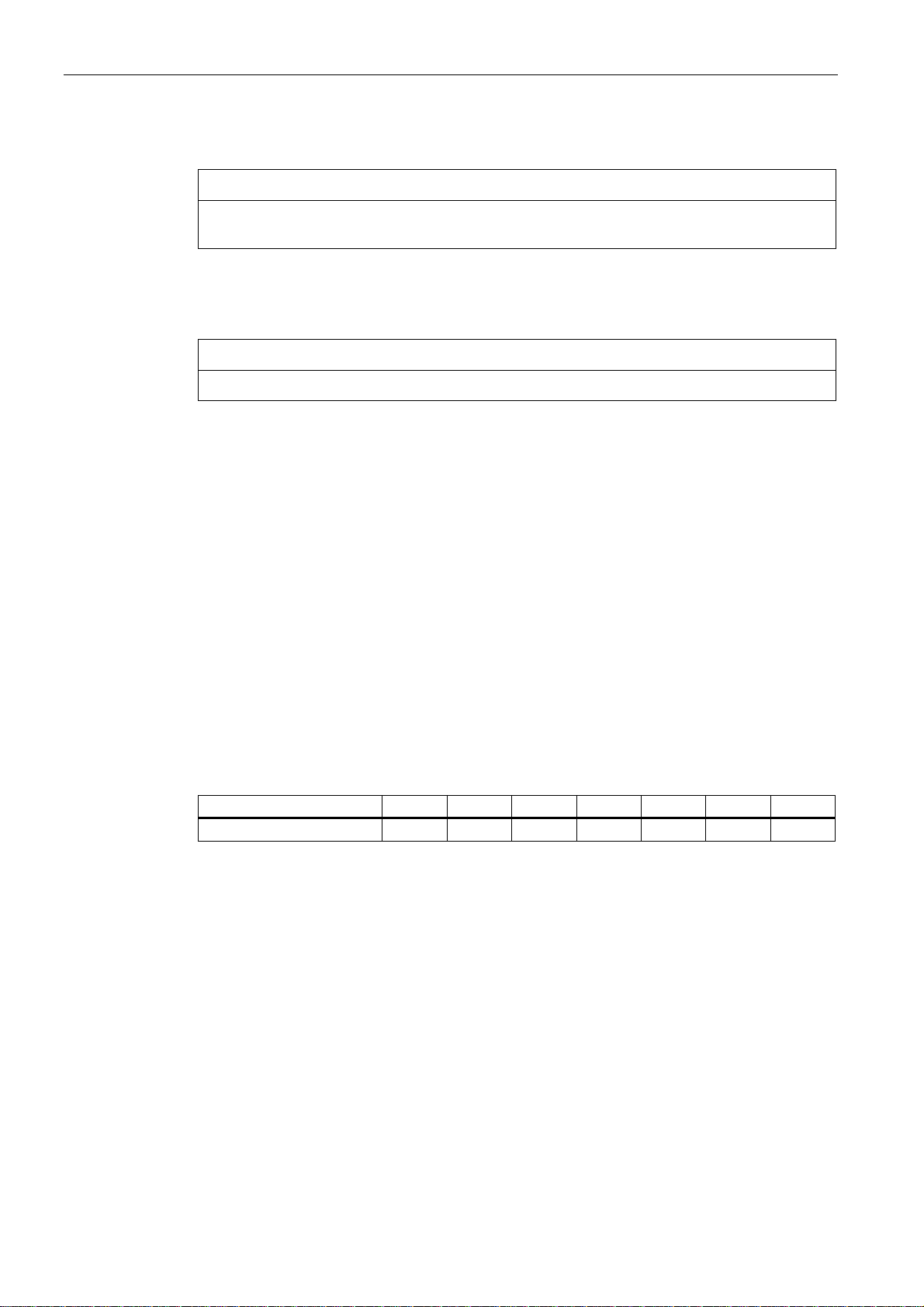
Maintenance
7.3 Corrective Maintenance
Installing the active parts of the bearings
NOTICE
Before mounting the bearings, ensure that the parts and components that are to be located
on the shaft inside the bearing have been mounted beforehand!
To fit the bearings on the shaft, heat them up to about 80°C in oil or air.
Then push the bearings onto the shaft up to its shoulder.
NOTICE
Avoid any heavy blows that might damage the bearings.
Fill the bearings with specified grease (see section entitled "Types of grease") until it is flush.
Also observe the following installation condition:
● If rotary shaft seals without helical springs are installed, the replacement part must also
be installed without a spring.
[ID: 378.01]
7.3.4 Screw-type connections
Tightening torque for screwed union connections
The screwed union connections with metal contact surfaces (end shields, active bearing
parts, terminal box parts bolted onto the stator frame) should be tightened to the following
torque with a tolerance of ± 10 %, depending on the thread size.
Table 7-3 Tightening torque for screwed union connections
Thread size M6 M8 M10 M12 M16 M20 M24
Tightening torque [Nm] 8 20 40 70 170 340 600
Please refer to the relevant sections and drawings for all other tightening torques (electrical
connections and bolted connections for parts with flat gaskets).
Bolt locking devices
Nuts or bolts that are mounted together with locking, resilient and/or force-distributing
elements (e.g., safety plates, spring-lock washers, etc.) must be refitted together with
identical, fully functional elements.
Always replace keyed elements.
[ID: 379.01]
A5E00215731A AD
62 Siemens AG Operating Instructions 2.02 1PL618
Page 65

Maintenance
7.3 Corrective Maintenance
7.3.5 Replacing the sensor module
See also
Only trained service engineers are authorized to replace the sensor module.
WARNING
Motor-specific sensor module
The Sensor Module contains motor-specific and sensor-specific data and an electronic
nameplate.
If you operate a different Sensor Module on the motor, this can result in serious injury or
death, or cause considerable material damage.
Only operate the sensor module on the original motor. Do not install the sensor module on
other motors. Do not replace the sensor module with a sensor module from a different
motor.
[ID 967.01]
Siemens Service Center (Page 15)
A5E00215731A AD
Siemens AG Operating Instructions 2.02 1PL618
63
Page 66

Page 67

Spare parts
8.1 Orders for spare parts
Ordering data
Please state the following when ordering spare parts:
● Precise part designation of the spare part and associated spare part number according to
the spare part list,
● Machine type,
● Serial number of the motor,
The motor type and serial number can be found on the rating plate. The serial number is
also stamped on the end face of the shaft end on the drive end.
● Serial number of the motor.
Example:
● End shield, drive end (part 5.00)
● See rating plate for motor type and serial number
Commercially available, standard components can be used, but ensure that they have the
same construction type, dimensions, strength class etc.
8
When replacing rolling-contact bearings, in addition to the bearing identification code, the
replacement code for the bearing version is also required. Both of these codes are specified
on the lubricant plate and in the motor documentation, or on the installed bearing.
[ID: 382.02]
A5E00215731A AD
Siemens AG Operating Instructions 2.02 1PL618
65
Page 68

Spare parts
8.2 Spare parts 1PL6
8.2 Spare parts 1PL6
Spare parts
Figure 8-1 Spare parts 1PL6
A5E00215731A AD
66 Siemens AG Operating Instructions 2.02 1PL618
Page 69

Spare parts
8.2 Spare parts 1PL6
Table 8-1 Spare Parts
Spare part no. Description
3.10 Gamma ring
3.40 Deep-groove ball bearings (floating bearing)
3.41 Cylindrical-roller bearing
3.47 Plain washer
3.60 Inner bearing cap
4.30 Retaining ring
4.40 Deep-groove ball bearing (locating bearing)
4.50 Inner bearing cap
5.00 End shield (DE)
6.00 End shield (NDE)
6.44 Cover
6.80 Sensor cover
8.00 Rotor, complete
10.00 Stator housing (with laminated core and winding)
10.53 Hoisting lug
13.80 Grease nipple
Terminal box
20.20 Terminal box with terminal support
20.30 Lid (terminal box)
20.50 Entry plate (terminal box)
32.12 Fan unit complete
55.12 Speed sensor
55.63 Torque transmission element
55.71 Cable with plug connector
[ID: 387.01]
A5E00215731A AD
Siemens AG Operating Instructions 2.02 1PL618
67
Page 70

Page 71

Notes
9
________________________________________________________________________________
________________________________________________________________________________
________________________________________________________________________________
________________________________________________________________________________
________________________________________________________________________________
________________________________________________________________________________
________________________________________________________________________________
________________________________________________________________________________
________________________________________________________________________________
________________________________________________________________________________
________________________________________________________________________________
________________________________________________________________________________
________________________________________________________________________________
________________________________________________________________________________
________________________________________________________________________________
________________________________________________________________________________
________________________________________________________________________________
A5E00215731A AD
Siemens AG Operating Instructions 2.02 1PL618
69
Page 72

Notes
________________________________________________________________________________
________________________________________________________________________________
________________________________________________________________________________
________________________________________________________________________________
________________________________________________________________________________
________________________________________________________________________________
________________________________________________________________________________
________________________________________________________________________________
________________________________________________________________________________
________________________________________________________________________________
________________________________________________________________________________
________________________________________________________________________________
________________________________________________________________________________
________________________________________________________________________________
________________________________________________________________________________
________________________________________________________________________________
________________________________________________________________________________
________________________________________________________________________________
________________________________________________________________________________
________________________________________________________________________________
________________________________________________________________________________
A5E00215731A AD
70 Siemens AG Operating Instructions 2.02 1PL618
Page 73

Notes
________________________________________________________________________________
________________________________________________________________________________
________________________________________________________________________________
________________________________________________________________________________
________________________________________________________________________________
________________________________________________________________________________
________________________________________________________________________________
________________________________________________________________________________
________________________________________________________________________________
________________________________________________________________________________
________________________________________________________________________________
________________________________________________________________________________
________________________________________________________________________________
________________________________________________________________________________
________________________________________________________________________________
________________________________________________________________________________
________________________________________________________________________________
________________________________________________________________________________
________________________________________________________________________________
________________________________________________________________________________
A5E00215731A AD
Siemens AG Operating Instructions 2.02 1PL618
71
Page 74

Page 75

Index
B
Bearing seizure damage, 22
C
Condensation water, 23
D
Degree of protection, 20
E
External fan
Maintenance, 51
I
Initial inspection, 55
Inspection interval, 55
T
Tightening torque
Screwed union connections, 62
P
Preservation, 23
R
Rating plate, 16
S
Sensor module, 27, 63
Siemens Service Center, 15
Storage, 22
Storage location, 22
A5E00215731A AD
Siemens AG Operating Instructions 2.02 1PL618
73
Page 76

Page 77

Page 78

Page 79

AB U151 Herstellererklärung
AB U161 Konformitätserklärung
Page 80

 Loading...