

Page 1

Three-phase induction motor
AC COMPACT DRIVES
Type 1PH818., 1PH822., 1PH828.
A5E02605207A AA
Operating Instructions • 07/2009
ac motor
Page 2

08.07.2009 15:28
Page 3

Introduction
1
Safety notes
2
Description
3
Preparations for use
4
Assembling
5
Connection
6
Commissioning
7
Operation
8
Maintenance
9
Spare parts
10
Disposal
11
Appendix
A
Three-phase induction motor
A
C COMPACT DRIVES
1PH818., 1PH822., 1PH828.
Operating Instructions
Edition 07/2009
Page 4
Legal information
Warning notice system
This manual contains notices you have to observe in order to ensure your personal safety, as well as to prevent
damage to property. The notices referring to your personal safety are highlighted in the manual by a safety alert
symbol, notices referring only to property damage have no safety alert symbol. These notices shown below are
graded according to the degree of danger.
DANGER
indicates that death or severe personal injury will result if proper precautions are not taken.
WARNING
indicates that death or severe personal injury may result if proper precautions are not taken.
CAUTION
with a safety alert symbol, indicates that minor personal injury can result if proper precautions are not taken.
CAUTION
without a safety alert symbol, indicates that property damage can result if proper precautions are not taken.
NOTICE
indicates that an unintended result or situation can occur if the corresponding information is not taken into
account.
If more than one degree of danger is present, the warning notice representing the highest degree of danger will
be used. A notice warning of injury to persons with a safety alert symbol may also include a warning relating to
property damage.
Qualified Personnel
The device/system may only be set up and used in conjunction with this documentation. Commissioning and
operation of a device/system may only be performed by qualified personnel. Within the context of the safety notes
in this documentation qualified persons are defined as persons who are authorized to commission, ground and
label devices, systems and circuits in accordance with established safety practices and standards.
Proper use of Siemens products
Note the following:
WARNING
Siemens products may only be used for the applications described in the catalog and in the relevant technical
documentation. If products and components from other manufacturers are used, these must be recommended
or approved by Siemens. Proper transport, storage, installation, assembly, commissioning, operation and
maintenance are required to ensure that the products operate safely and without any problems. The permissible
ambient conditions must be adhered to. The information in the relevant documentation must be observed.
Trademarks
All names identified by ® are registered trademarks of the Siemens AG. The remaining trademarks in this
publication may be trademarks whose use by third parties for their own purposes could violate the rights of the
owner.
Disclaimer of Liability
We have reviewed the contents of this publication to ensure consistency with the hardware and software
described. Since variance cannot be precluded entirely, we cannot guarantee full consistency. However, the
information in this publication is reviewed regularly and any necessary corrections are included in subsequent
editions.
Siemens AG
Industry Sector
Postfach 48 48
90026 NÜRNBERG
GERMANY
Ordernumber: A5E02446774A AA
Ⓟ 07/2009
Copyright © Siemens AG 2008.
Technical data subject to change
Page 5

A5E02605207A AA
Siemens AG Operating Instructions V1.0 1PH8
3
Table of contents
1 Introduction................................................................................................................................................ 9
2 Safety notes............................................................................................................................................. 11
2.1 The five safety rules:....................................................................................................................11
2.2 Qualified personnel ......................................................................................................................12
2.3 Safe handling ...............................................................................................................................12
2.4 Electrostatic sensitive devices .....................................................................................................14
2.5 Electromagnetic compatibility (EMC)...........................................................................................15
2.5.1 Interference immunity ..................................................................................................................15
2.5.2 Emitted interference.....................................................................................................................15
3 Description............................................................................................................................................... 17
3.1 Applications..................................................................................................................................17
3.2 Rating plate..................................................................................................................................17
3.3 Layout ..........................................................................................................................................18
4 Preparations for use ................................................................................................................................ 21
4.1 Shipment and packaging .............................................................................................................21
4.1.1 Scope of supply ...........................................................................................................................21
4.2 Transport and storage..................................................................................................................21
4.2.1 Transporting.................................................................................................................................21
4.2.2 Storage.........................................................................................................................................24
4.2.3 Protecting the cooling-water system............................................................................................27
5 Assembling.............................................................................................................................................. 29
5.1 Heat-resistant mounting parts......................................................................................................29
5.2 Installation....................................................................................................................................29
5.3 Aligning the machine....................................................................................................................30
5.4 Securing the machine ..................................................................................................................31
5.5 Pushing on the power output elements .......................................................................................32
5.6 Condensation drain holes ..................................................................................................
..........33
6 Connection .............................................................................................................................................. 35
6.1 Mechanical connection ................................................................................................................35
6.1.1 Cooling water quality....................................................................................................................35
6.1.2 Connecting the cooling water supply ...........................................................................................36
6.2 Electrical connection ....................................................................................................................37
6.2.1 Safety note for the DRIVE-CLiQ interface ...................................................................................37
6.2.2 Cable entry and routing................................................................................................................37
6.2.3 Electrical connection data ............................................................................................................38
6.2.4 Terminal designation....................................................................................................................39
Page 6

Table of contents
A5E02605207A AA
4 Siemens AG Operating Instructions V1.0 1PH8
6.2.5 Connection with cable lugs ......................................................................................................... 39
6.2.6 Connecting the ground conductor............................................................................................... 40
6.2.7 Internal equipotential bonding..................................................................................................... 41
6.2.8 Circuit diagram ............................................................................................................................ 41
6.2.9 Connecting the speed encoder ................................................................................................... 42
6.2.10 Connecting the temperature sensor............................................................................................ 42
6.2.11 Connection to a converter........................................................................................................... 43
6.2.12 Converter operation on a grounded network .............................................................................. 43
6.2.13 Final steps................................................................................................................................... 44
7 Commissioning ........................................................................................................................................ 45
7.1 Measures to be performed prior to commissioning..................................................................... 45
7.2 Trial run ....................................................................................................................................... 46
7.3 Checking insulation resistance ................................................................................................... 46
7.4 Switching on................................................................................................................................ 49
8 Operation................................................................................................................................................. 51
8.1 Safety notes during operation ..................................................................................................... 51
8.2 Do not operate without cooling water supply .............................................................................. 51
8.3 Stoppages ................................................................................................................................... 52
8.4 Switching off................................................................................................................................ 52
8.5 Faults........................................................................................................................................... 53
8.5.1 Electrical faults ............................................................................................................................ 53
8.5.2 Mechanical faults ........................................................................................................................ 54
9 Maintenance ............................................................................................................................................ 55
9.1 Inspection and maintenance ....................................................................................................... 55
9.1.1 Inspection.................................................................................................................................... 55
9.1.1.1 Initial inspection........................................................................................................................... 55
9.1.1.2 General inspection ...................................................................................................................... 56
9.1.1.3 Rolling-contact bearing inspection .............................................................................................. 56
9.1.1.4 Changing bearings when using permanently lubricated rolling-contact bearings....................... 57
9.1.2 Maintenance.............................................................................................................
................... 57
9.1.2.1 Safety instructions for maintenance............................................................................................ 57
9.1.2.2 Maintenance intervals ................................................................................................................. 57
9.1.2.3 Rolling-contact bearings.............................................................................................................. 58
9.1.2.4 Cleaning the spent grease chamber ........................................................................................... 58
9.1.2.5 Lubrication................................................................................................................................... 59
9.1.2.6 Maintaining the cooling water system......................................................................................... 60
9.2 Repair.......................................................................................................................................... 61
9.2.1 Disassembling the machine ........................................................................................................ 61
9.2.2 Assembling the machine............................................................................................................. 62
9.2.3 Removing and installing the protecting ring................................................................................ 63
9.2.4 Removing and mounting the bearing end shields....................................................................... 64
9.2.5 Removing and mounting the speed sensor ................................................................................ 64
9.2.6 Connecting the speed encoder ................................................................................................... 67
9.2.7 Replacing the DRIVE-CLiQ interface (encoder module) ............................................................ 67
9.2.8 Screw-type connections.............................................................................................................. 68
10 Spare parts.............................................................................................................................................. 69
10.1 Ordering data .............................................................................................................................. 69
Page 7

Table of contents
A5E02605207A AA
Siemens AG Operating Instructions V1.0 1PH8
5
10.2 Replacing rolling-contact bearings...............................................................................................69
10.3 Using commercially available spare parts ...................................................................................69
10.4 Ordering spare parts from Spares on Web..................................................................................69
10.5 Motor, complete ...........................................................................................................................71
10.6 Rolling-contact bearing bush drive end, mounted gearing, with regreasing................................72
10.7 Rolling-contact bearing bush drive end, belt coupling .................................................................73
10.8 Rolling-contact bearing bush drive end, coupling output, with regreasing ..................................74
10.9 Rolling-contact bearing bush drive end, coupling output, with permanent lubrication.................75
10.10 Rolling-contact bearing bush non-drive end, with permanent lubrication....................................76
10.11 Rolling-contact bearing bush non-drive end, with regreasing (shaft height 180, 225) ................77
10.12 Rolling-contact bearing bush non-drive end, with regreasing (shaft height 280) ........................78
10.13 Rolling-contact bearing bush non-drive end "Performance"........................................................79
10.14 Terminal box ................................................................................................................................80
10.15 Speed encoder (shaft heights 180 and 225)................................................................................81
10.16 Speed encoder (shaft height 280) ...............................................................................................82
11 Disposal................................................................................................................................................... 83
11.1 Introduction ..................................................................................................................................83
11.2 Preparing for disassembly ...........................................................................................................83
11.3 Dismantling the machine..............................................................................................................83
11.4 Disposal of components...............................................................................................................84
A Appendix.................................................................................................................................................. 85
A.1 SIEMENS Service Center ............................................................................................................85
A.2 EC Declaration of Conformity ......................................................................................................86
Index........................................................................................................................................................ 93
Tables
Table 3-1
Elements on the rating plate ........................................................................................................17
Table 3-2 Machine design............................................................................................................................18
Table 3-3 Types of construction...................................................................................................................19
Table 3-4 Rolling-contact bearing variants...................................................................................................20
Table 4-1 Tightening torque for rotor shipping brace...................................................................................24
Table 5-1 Noise emissions...........................................................................................................................29
Table 5-2 Permissible deviations when aligning the motor..........................................................................31
Table 6-1 Cooling water specification ..........................................................................................................35
Table 6-2 Rate of flow and pressure drop....................................................................................................36
Table 6-3 Electrical connection data............................................................................................................39
Page 8

Table of contents
A5E02605207A AA
6 Siemens AG Operating Instructions V1.0 1PH8
Table 6-4 Terminal designations using the 1U1-1 as an example.............................................................. 39
Table 6-5 Tightening torque for the terminal box cover fixing screws......................................................... 44
Table 7-1 Stator winding insulation resistance at 25 °C ............................................................................. 47
Table 8-1 Electrical faults ............................................................................................................................ 53
Table 8-2 Mechanical faults ........................................................................................................................ 54
Table 9-1 Measures after operating times or intervals................................................................................ 58
Table 9-2 Rolling-contact bearing greases ................................................................................................. 59
Table 9-3 Tightening torque for screwed union connections ...................................................................... 68
Table 10-1 Spare parts for complete motor .................................................................................................. 71
Table 10-2 Spare parts for rolling-contact bearing bush drive end with mounted gearing, with
regreasing ................................................................................................................................... 72
Table 10-3 Spare parts for rolling-contact bearing bush drive end with belt coupling, with regreasing........ 73
Table 10-4 Spare parts for rolling-contact bearing bush drive end, with coupling output, with
regreasing ................................................................................................................................... 74
Table 10-5 Spare parts for rolling-contact bearing bush drive end, with coupling output, with
permanent lubrication.................................................................................................................. 75
Table 10-6 Spare parts: antifriction-bearing insert, non-drive end, permanent lubrication........................... 76
Table 10-7 Spare parts for rolling-contact bearing bush non-drive end, with regreasing, shaft height
180 / 225 ..................................................................................................................................... 77
Table 10-8 Spare parts for rolling-contact bearing bush non-drive end, with regreasing............................. 78
Table 10-9 Spare parts for rolling-contact bearing bush non-drive end with regreasing .............................. 79
Table 10-10 Spare parts for terminal box........................................................................................................ 80
Table 10-11 Spare parts for speed encoder (shaft heights 180 and 225) ...................................................... 81
Table 10-12 Spare parts for speed encoder (shaft height 280) ...................................................................... 82
Table A-1 Siemens Service Center contact details ..................................................................................... 85
Figures
Figure 3-1
Schematic layout of rating plate.................................................................................................. 17
Figure 4-1 Lifting the machine ...................................................................................................................... 23
Figure 4-2 Rotor shipping brace................................................................................................................... 24
Figure 5-1 Aligning the machine................................................................................................................... 31
Figure 5-2 Water drain holes ........................................................................................................................ 33
Figure 6-1 Connection using cable lugs ....................................................................................................... 40
Figure 6-2 Detailed view: Connection point ① for ground conductor........................................................... 41
Figure 6-3 Detailed view: Plug-in connection ............................................................................................... 42
Figure 9-1 Grease nipple.............................................................................................................................. 60
Figure 9-2 Fitting the protecting ring............................................................................................................. 63
Page 9

Table of contents
A5E02605207A AA
Siemens AG Operating Instructions V1.0 1PH8
7
Figure 9-3 Detailed view of the speed encoder.............................................................................................65
Figure 9-4 Electrical connection of the speed sensor ...................................................................................67
Figure 10-1 Motor, complete ...........................................................................................................................71
Figure 10-2 Rolling-contact bearing bush drive end with mounted gearing, with regreasing.........................72
Figure 10-3 Rolling-contact bearing bush drive end with belt coupling, with regreasing................................73
Figure 10-4 Rolling-contact bearing bush drive end, with coupling output, with regreasing...........................74
Figure 10-5 Rolling-contact bearing bush drive end, with coupling output, with permanent lubrication .........75
Figure 10-6 Rolling-contact bearing bush non-drive end, permanent lubrication ...........................................76
Figure 10-7 Rolling-contact bearing bush non-drive end, with regreasing, shaft height 180 / 225.................77
Figure 10-8 Rolling-contact bearing bush non-drive end, with regreasing, shaft height 280..........................78
Figure 10-9 Rolling-contact bearing bush non-drive end with regreasing.......................................................79
Figure 10-10 Terminal box ................................................................................................................................80
Figure 10-11 Speed encoder (shaft heights 180 and 225)................................................................................81
Figure 10-12 Speed encoder (shaft height 280) ...............................................................................................82
Page 10

Table of contents
A5E02605207A AA
8 Siemens AG Operating Instructions V1.0 1PH8
Page 11

A5E02605207A AA
Siemens AG Operating Instructions V1.0 1PH8
9
Introduction
1
About these operating instructions
These operating instructions describe the machine and explain best practices in machine
handling, from initial delivery to final disposal of the equipment.
Read these operating instructions before you handle the machine to become familiar with its
design and operating principles and thus ensure safe, problem-free machine operation and
long service life.
If you find any mistakes or have suggestions for improvements, please contact the
Siemens Service Center (Page 85).
Page 12

Introduction
2.1 The five safety rules:
A5E02605207A AA
10 Siemens AG Operating Instructions V1.0 1PH8
Page 13

A5E02605207A AA
Siemens AG Operating Instructions V1.0 1PH8
11
Safety notes
2
This electric machine has been designed and built in accordance with the specifications in
the Low-Voltage Directive 2006/95/EG and is intended for use in industrial systems as an
incomplete machine in terms of Machinery Directive 98/37/EG . In accordance with the
Machinery Directive we are obliged to point out that commissioning in the European
Community is forbidden until it has been established that the system in which the machine is
to be fitted conforms with the Machinery Directive. Please observe the country-specific
regulations when using the electric machine outside the European Community.
Follow the local and industry-specific safety and setup regulations.
The persons responsible for the plant must ensure the following:
● Planning and configuration work and all work carried out on and with the machine is only
to be done by qualified personnel.
● The operating instructions must always be available for all work.
● The technical data as well as the specifications relating to the permissible installation,
connection, ambient and operating conditions are taken into account at all times.
● The specific setup and safety regulations as well as regulations on the use of personal
protective equipment are observed.
Note
Use the services and support provided by the Siemens Service Center (Page 85) for
planning, installation, commissioning and servicing work.
In the individual chapters of this document, you will find safety instructions that must be
obeyed absolutely, for your own safety, to protect other people and to avoid damage to
property.
Observe the following safety instructions for all activities on and with the machine.
2.1 The five safety rules:
For your personal safety and to prevent material damage when working on the machine,
always observe the safety instructions and the following five safety rules, according to
DIN VDE 0105. Apply the five safety rules in the order stated before starting work at the
machine.
Five safety rules
1. Disconnect the system.
Be sure to disconnect auxiliary circuits, e.g. anti-condensation heaters, etc.
2. Protect against reconnection.
3. Make sure that the equipment is at zero voltage
Page 14
Safety notes
2.2 Qualified personnel
A5E02605207A AA
12 Siemens AG Operating Instructions V1.0 1PH8
4. Ground and short-circuit
5. Cover or enclose adjacent components that are still live.
When work has been completed, remove these measures in reverse order.
2.2 Qualified personnel
All work at the machine should be carried out by qualified personnel only. For the purpose of
this documentation, qualified personnel is taken to mean people who fulfill the following
requirements:
● Through appropriate training and experience, they are able to recognize and avoid risks
and potential dangers in their particular field of activity.
● They have been instructed to carry out work on the machine by the appropriate person
responsible.
2.3 Safe handling
Workplace safety depends on the attentiveness, care, and common sense of the personnel
who install, operate, and maintain the machine. In addition to the safety measures cited, as a
matter of principle, the use of caution is necessary when you are near the machine. Always
pay attention to your safety.
Also observe the following to prevent accidents:
● General safety regulations applicable in the country where the machine is deployed.
● Manufacturer-specific and application-specific regulations
● Special agreements made with operator
● Separate safety instructions supplied with the machine
WARNING
Live parts
Electric machines contain live parts.
Fatal or severe injuries and substantial material damage can occur if the covers are
removed or if the machine is not handled, operated, or maintained properly.
Always observe the "five safety rules (Page 11)" when carrying out any work on the
machine.
Only remove the covers using the methods described by these operating instructions.
Operate the machine properly.
Perform regular maintenance on the machine.
Page 15
Safety notes
2.3 Safe handling
A5E02605207A AA
Siemens AG Operating Instructions V1.0 1PH8
13
WARNING
Rotating components
Electric machines contain dangerous rotating parts.
Fatal or severe injuries and substantial material damage can occur if the covers are
removed or if the machine is not handled, operated, or maintained properly.
Only remove the covers using the methods described by these operating instructions.
Operate the machine properly.
Perform regular maintenance on the machine.
Secure free-standing shaft ends.
WARNING
Hot surfaces
Electric machines have hot surfaces.
Fatal or severe injuries and substantial material damage can occur if the covers are
removed or if the machine is not handled, operated, or maintained properly.
Allow the machine to cool before starting work on the machine.
Only remove the covers using the methods described by these operating instructions.
Operate the machine properly.
CAUTION
Hazardous substances
Chemical substances required for the setup, operation and maintenance of machines can
present a health risk.
Poisoning, skin damage, cauterization of the respiratory tract, and other health damage
may result.
Read the information in these operating instructions and the product information
supplied by the manufacturer.
Observe the relevant safety regulations and wear the personal protective equipment
specified.
CAUTION
Flammable substances
Chemical substances required for the setup, operation and maintenance of machines may
be flammable.
Burns and other damage to health and material may result.
Read the information in these operating instructions and the product information
supplied by the manufacturer.
Observe the relevant safety regulations and wear the personal protective equipment
specified.
Page 16
Safety notes
2.4 Electrostatic sensitive devices
A5E02605207A AA
14 Siemens AG Operating Instructions V1.0 1PH8
2.4 Electrostatic sensitive devices
ESD protective measures
CAUTION
Electrostatic discharge
Electronic modules contain components that can be destroyed by electrostatic discharge.
These modules can be easily destroyed by improper handling.
To protect your equipment against damage, follow the instructions given below.
Never touch electronic modules unless absolutely necessary in the course of
maintenance and repair procedures.
If the modules have to be touched, the body of the person concerned must be
electrostatically discharged immediately beforehand and be grounded.
Electronic modules should not be brought into contact with electrically insulating
materials such as plastic foil, plastic parts, insulating table supports or clothing made of
synthetic fibers.
Always place electrostatic sensitive devices on conductive bases.
Always pack, store and transport electronic modules or components in conductive
packaging, e.g. metallized plastic or metal containers, conductive foam material or
domestic aluminum foil.
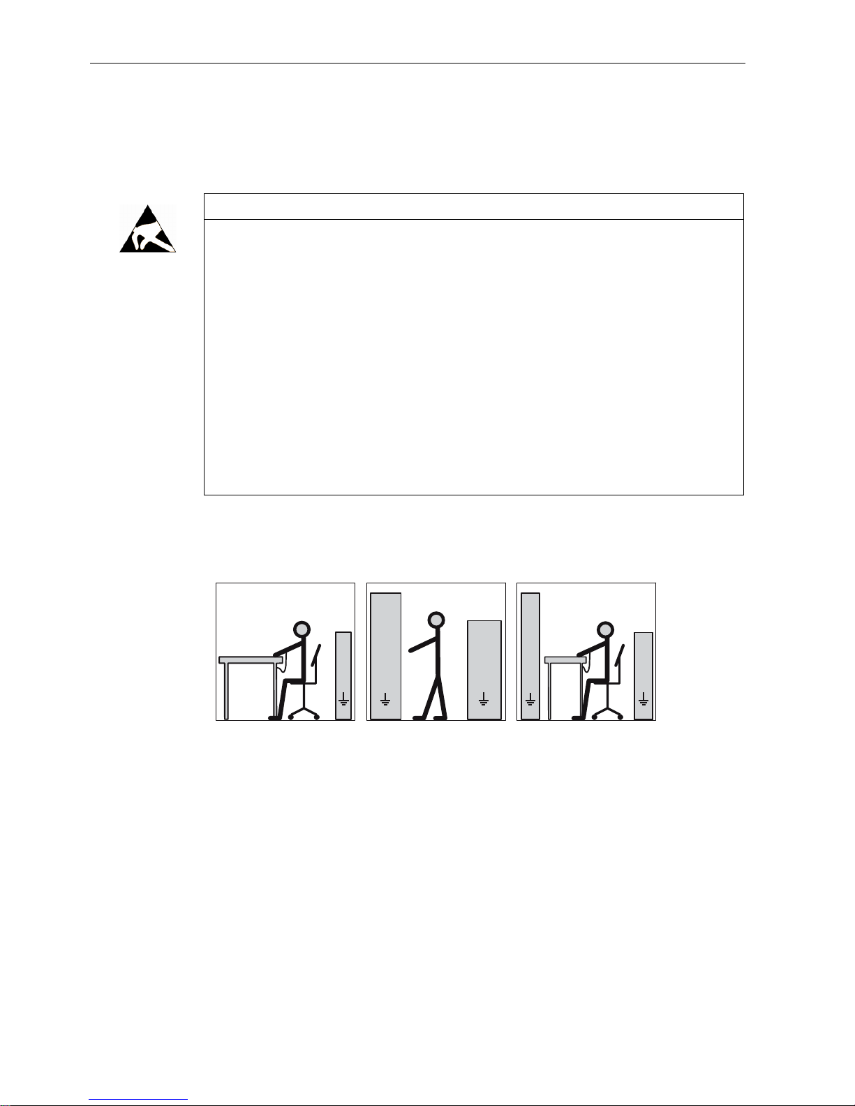
The necessary ESD protective measures for electrostatic sensitive devices are illustrated
once again in the following drawings:
d
ff f f
b
e
aa a
cc c
e
b
f
dd
(1) (2) (3)
e
a
(1) Sitting (2) Standing (3) Standing/sitting
a = conductive floor surface b = ESD table c = ESD shoes
d = ESD overall e = ESD wristband f = cabinet ground
connection
See also
Replacing the DRIVE-CLiQ interface (encoder module) (Page 67)
Page 17
Safety notes
2.5 Electromagnetic compatibility (EMC)
A5E02605207A AA
Siemens AG Operating Instructions V1.0 1PH8
15
2.5 Electromagnetic compatibility (EMC)
This machine is designed in accordance with IEC / EN 60034 and when used as prescribed
it satisfies the requirements of European Directive 2004/108/EC on Electromagnetic
Compatibility.
2.5.1 Interference immunity
The machine fulfills the requirements regarding interference immunity in conformity with IEC
/ EN 61000-6-2.
When using machines with integrated sensors (PT100, PTC thermistors), the manufacturer
of the overall plant must himself ensure sufficient interference immunity by selecting suitable
sensor signal leads and evaluation units.
2.5.2 Emitted interference
WARNING
Interference on electronic devices through electromagnetic fields
Electromagnetic fields are generated by the operation of electrical power engineering
installations such as motors, converters or transformers. Electromagnetic fields can
interfere with electronic devices,
resulting in malfunctioning of those devices. The operation of heart pacemakers can be
impaired, potentially leading to damage to a person's health or even death. It is therefore
forbidden for persons with heart pacemakers to come into the vicinity of the machine. Data
may be lost from magnetic or electronic data media.
Ensure that the personnel working in these areas are adequately protected from any
harm by making appropriate arrangements, such as erecting identifying markings, safety
barriers and warning signs and giving safety talks.
Observe the nationally applicable health and safety regulations.
Do not carry any magnetic or electronic data media with you.
Page 18

Safety notes
2.5 Electromagnetic compatibility (EMC)
A5E02605207A AA
16 Siemens AG Operating Instructions V1.0 1PH8
Page 19

A5E02605207A AA
Siemens AG Operating Instructions V1.0 1PH8
17
Description
3
3.1 Applications
Three-phase motors of the 1PH8 series are used as industrial drives. They have been
designed for a wide range of applications in the fields of drive engineering and power
conversion.
They are characterized by their high power density, ruggedness, long lifetime, and overall
reliability.
3.2 Rating plate
The motor rating plate shows the technical specifications applicable to the supplied motor.
Figure 3-1 Schematic layout of rating plate
Table 3-1 Elements on the rating plate
No. Description No. Description
010 Order number 170 Rated speed nN (2)
012 Consecutive number, part of serial number 180 Operating mode (2)
020 Serial number 185 Code for operating point 2
Page 20

Description
3.3 Layout
A5E02605207A AA
18 Siemens AG Operating Instructions V1.0 1PH8
No. Description No. Description
025 UL approval 190 Rated voltage VN (3)
026 (empty) 191 Switching mode 3
030 Type of construction 200 Rated current IN (3)
035 (empty) 210 Rated power PN (3)
036 (empty) 220 Power factor (3)
040 Degree of protection 230 Rated frequency fN (3)
045 Type of balancing 240 Rated speed nN (3)
049 Power factor (asynchronous) 250 Operating mode (3)
050 Rated voltage VN (1) 255 Code for operating point 3
051 Switching mode 1 270 Maximum current I
MAX
060 Rated current IN (1) 275 Maximum torque M
MAX
070 Rated power PN (1) 280 Maximum speed n
MAX
080 Power factor (1) 285 Temperature sensor
090 Rated frequency fN (1) 290 Tachometer/resolver
100 Rated speed nN (1) 295 Cooling method
110 Operating mode (1) 296 Throughput l/min (m3/s)
115 Code for operating point 1 297 System pressure
120 Rated voltage VN (2) 298 Maximum coolant temperature
121 Switching mode 2 315 Options (I)
130 Rated current IN (2) 320 Options (II)
140 Rated power PN (2) 325 Optional customer information
150 Power factor (2) 330 Anti-condensation heater / place holder
160 Rated frequency fN (2) 335 Weight
3.3 Layout
Rotor
This machine is an induction motor for low voltage with squirrel-cage induction motor and
integrated cooling circuit.
Machine design
The regulations and standards underlying the design and testing of this machine are stated
on the rating plate. The machine design basically complies with the following standards:
Table 3-2 Machine design
Feature Standard
Ratings and operating performance IEC / EN 60034-1
Degree of protection IEC / EN 60034-5
Cooling IEC / EN 60034-6
Type of construction IEC / EN 60034-7
Page 21

Description
3.3 Layout
A5E02605207A AA
Siemens AG Operating Instructions V1.0 1PH8
19
Feature Standard
Noise emission IEC / EN 60034-9
Vibration severity grades IEC / EN 60034-14
Drive
The speed of the machine is controlled by a frequency converter.
Types of construction
The motor is available in the following basic types of construction and further optional types
of construction with additional application possibilities.
Table 3-3 Types of construction
Basic types of construction Other applications in construction type
IM B3 IM B6①, IM B7①, IM B8①, IM V6
IM V15 IM V5 IM B35 IM B5, IM V3, IM V35
①
Not for 1PH828.
The machine is supplied with two assembled lifting eyes. For IM V5 and IM V15 types of
construction with "shaft extension pointing downward", the machine is equipped with two
additional Vario eye bolts.
Cooling circuit
The cooling circuit consists of high-grade steel tubes that are directly integrated into the
laminated stator core. The machine is in an enclosed design which incorporates a cooling
circuit, cooling method IC 37W in accordance with IEC / EN 60034-6.
Cooling capacity
To ensure adequate cooling of the motor, it is essential to adhere to the specified cooling
water rate and cooling water quality (Page 35).
Degree of protection
The machine is available with degree of protection IP55.
Supplementary devices
A KTY 84 temperature sensor is installed (Page 42) in the stator winding for winding control.
Depending on the order options, various supplementary devices such as encoder systems
can be either installed or mounted.
Page 22

Description
3.3 Layout
A5E02605207A AA
20 Siemens AG Operating Instructions V1.0 1PH8
Ambient conditions
The standard machines are not suitable for use in corrosive atmospheres, atmospheres with
a high salt content, or outdoor applications.
Bearings
The machines are equipped with different types of roller bearings depending on the version
and the operating conditions described in the order. If the motor is equipped with a
regreasing device, you will find the relevant data on the motor's lubricant plate.
The following rolling-contact bearing variants are available:
Table 3-4 Rolling-contact bearing variants
Design Bearings
Standard design and
"Performance"
Drive end deep-groove ball bearing as spring-loaded floating
bearing
Non-drive end deep-groove ball bearing as fixed bearing
Bearing design for increased
cantilever forces
Drive end cylindrical-roller bearing as spring-loaded floating
bearing
Non-drive end deep-groove ball bearing as fixed bearing
CAUTION
Permissible loads
Exceeding the permissible loads for the forces at the shaft end can cause damage to the
bearing and the motor. Not meeting the minimum transverse forces on cylindrical-roller
bearings can also result in damage.
Keep to the permissible loads in accordance with the catalog data.
Page 23

A5E02605207A AA
Siemens AG Operating Instructions V1.0 1PH8
21
Preparations for use
4
4.1 Shipment and packaging
4.1.1 Scope of supply
Checking the delivery for completeness
The drive systems are put together on an individual basis. When you take receipt of the
delivery, please check immediately whether the items delivered are in accordance with the
accompanying documents. Siemens will not accept any claims relating to items missing from
the delivery and which are submitted at a later date.
● Report any apparent transport damage to the delivery agent immediately.
● Report any apparent defects/missing components to the appropriate Siemens office
immediately.
These safety instructions are part of the scope of supply; keep them in a location where they
can be easily accessed.
4.2 Transport and storage
4.2.1 Transporting
Damage during transportation
Notify the shipping company immediately if you have found any damage to the motor after
delivery. Never commission a damaged motor.
Transporting
Please comply with the following instructions for transporting the motor.
Page 24

Preparations for use
4.2 Transport and storage
A5E02605207A AA
22 Siemens AG Operating Instructions V1.0 1PH8
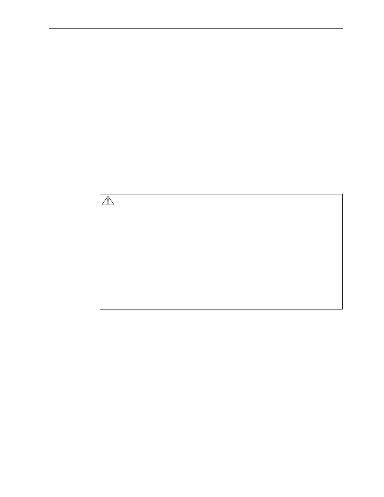
WARNING
Always transport and lift the motor on the lifting eyebolts
If you lift the motor by the cooling water pipe system, the pipes will be damaged and the
motor might be dropped. Death, serious injury, or material damage to the motor - even a
write-off - can result.
Do not attach the motor at the cooling water pipes when you have removed the bearing
end shields. The bearing end shields must always be mounted when you transport the
motor.
There are two lifting eyebolts for horizontal transport of the motor. In addition there are
two threads for vertical lifting with the shaft end pointing downwards. For this, the lifting
eyebolts and the threaded plugs have to be swapped around.
Only lift the motor at the lifting eyebolts on the bearing end shields. To hoist the motor,
in particular if there are built-on assemblies, use suitable cable-guidance or spreading
equipment.
Pay attention to the lifting capacity of the hoisting gear. The weight of the motor is
specified on the rating plate (Page 17).
Page 25
Preparations for use
4.2 Transport and storage
A5E02605207A AA
Siemens AG Operating Instructions V1.0 1PH8
23
Figure 4-1 Lifting the machine
Rotor shipping brace
Machines ordered with the "Increased transverse force" option are equipped with cylindricalroller bearings and a rotor shipping brace.
CAUTION
Transport damage if the rotor shipping brace device is not used.
The motor can be damaged if it is jolted during transport. Material damage can result.
Always transport the motor with the rotor shipping brace supplied. It must be securely
attached during transportation.
Only remove it before pushing on the drive element.
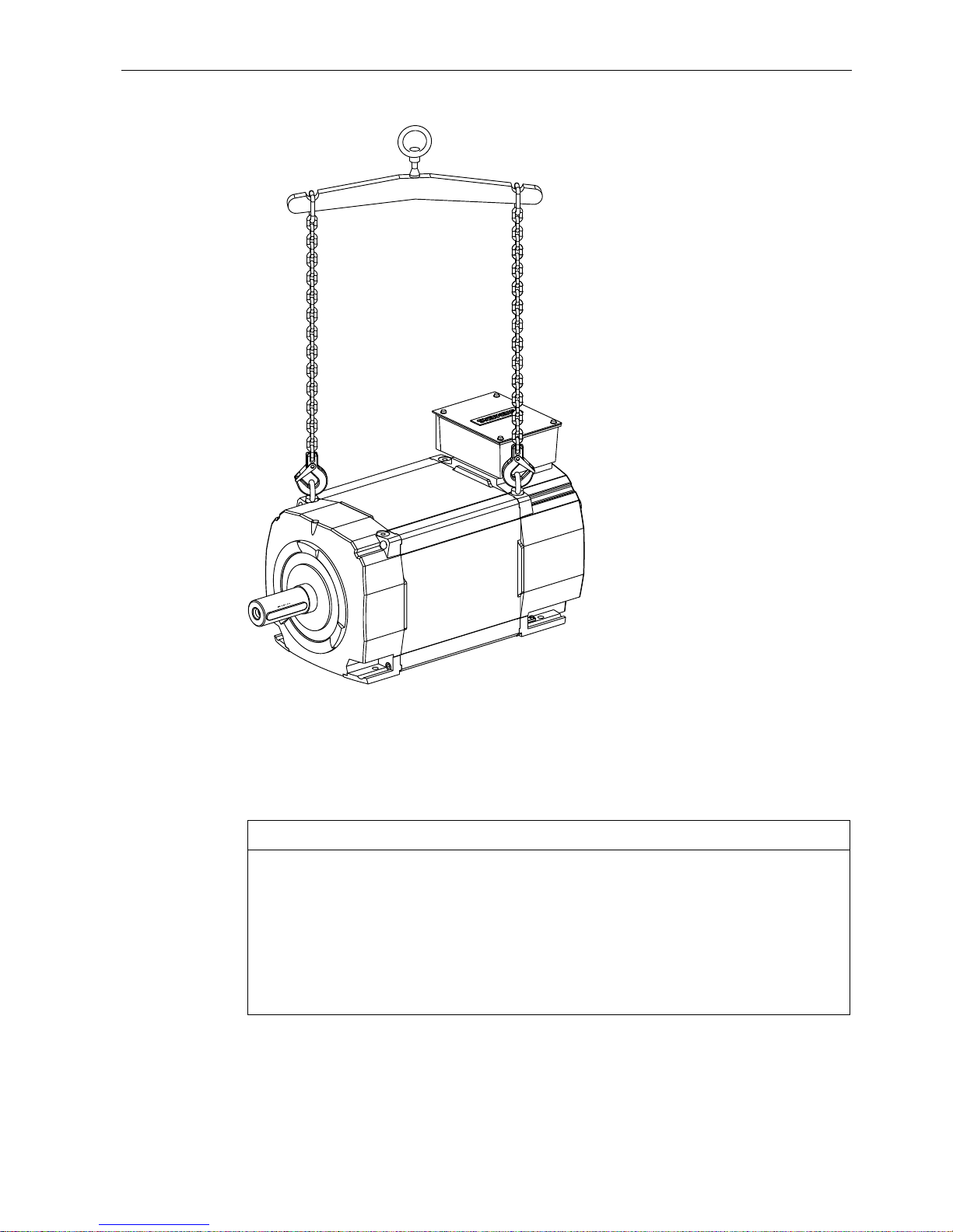
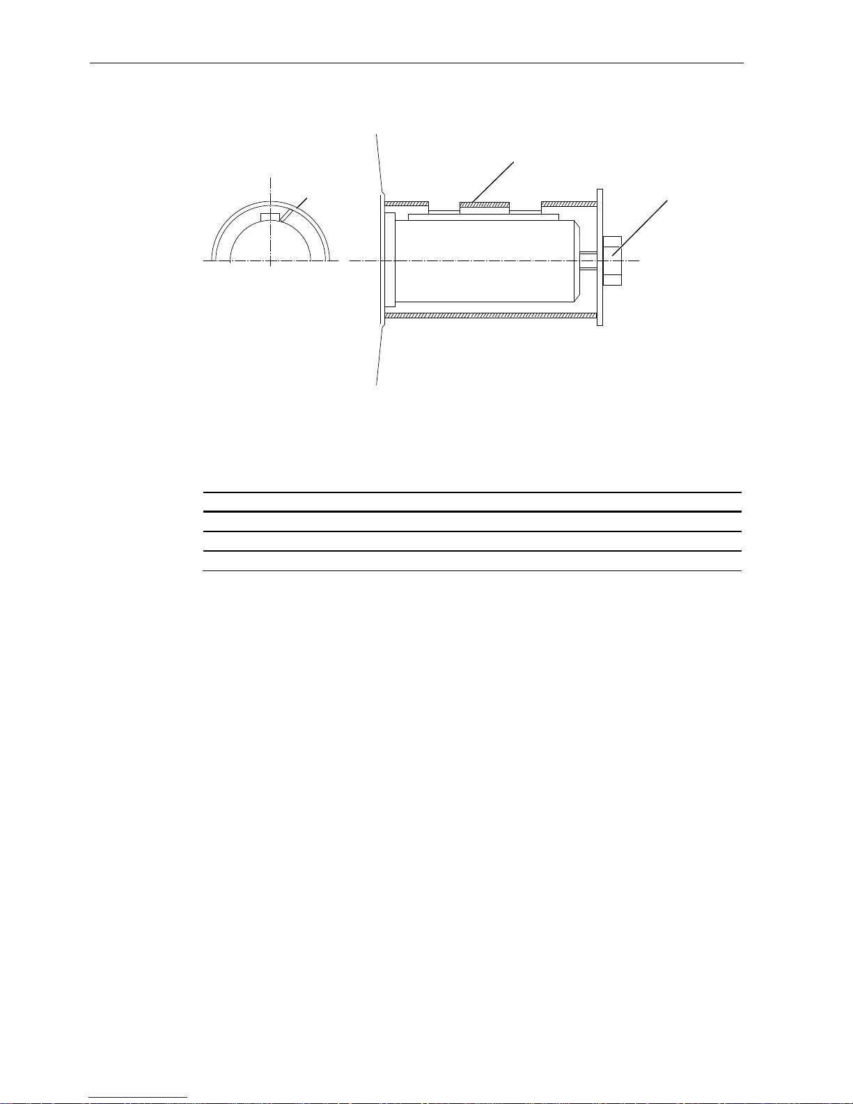
When the motor has to be transported after the drive element is pushed on you must
take other appropriate measures to fix the axial position of the rotor. Please refer to the
illustration below.
Page 26
Preparations for use
4.2 Transport and storage
A5E02605207A AA
24 Siemens AG Operating Instructions V1.0 1PH8
$
ཱི
① Sleeve
④ Shaft screw
Figure 4-2 Rotor shipping brace
Table 4-1 Tightening torque for rotor shipping brace
Type Thread in the shaft end Tightening torque Preload
1PH818. M20 50 Nm 12 kN
1PH822. M20 50 Nm 12 kN
1PH828. M24 100 Nm 20 kN
Transporting a motor that has been in operation
If you have already operated the motor and now want to transport it, proceed as follows:
1. Allow the motor to cool down.
2. Remove the connections provided by the customer.
3. Drain the cooling-water system and purge it carefully with air.
4. Fit the rotor shipping brace.
5. Always use only the lifting eyebolts on the bearing end shields to transport and lift the
motor.
4.2.2 Storage
The motors can be stored for up to two years in dry, dust-free and vibration-free rooms
without reducing the specified storage time.
Page 27

Preparations for use
4.2 Transport and storage
A5E02605207A AA
Siemens AG Operating Instructions V1.0 1PH8
25
CAUTION
Seizure damage to bearings
If the motors are stored incorrectly there is a risk of bearing seizure damage such as
brinelling, for example as a result of vibrations.
Read the following storage instructions.
Preparation
● Fit the rotor shipping brace.
● Apply a preserving agent such as Tectyl to bare external components such as shaft ends,
if this has not already been applied in the factory.
Storing indoors
CAUTION
Damage caused as a result of outdoor storage
Storing the machine outdoors can result in it being damaged. Ensure that the machine is
only stored in areas that comply with the following conditions.
● Store the motor in an area that meets the following criteria:
– Dry, dust-free, frost-free and vibration-free The relative air humidity should be lower
than 60% and the temperature should not drop below -15 °C in accordance with
EN 60034-1.
– Well ventilated
– Offers protection against extreme weather conditions
– The air in the storage area must not contain any harmful gases.
● Protect the motor from shocks and humidity.
● Cover the motor properly.
● Avoid contact corrosion:
– Every three months, remove the shipping brace and rotate the shaft end by hand.
– Then reattach the rotor shipping brace.
Page 28

Preparations for use
4.2 Transport and storage
A5E02605207A AA
26 Siemens AG Operating Instructions V1.0 1PH8
Protection against humidity
● If a dry storage area is not available, then take the following precautions:
– Wrap the motor in humidity-absorbent material and then wrap it in film to create an air-
tight unit.
– Include several bags of desiccant in the seal-tight packaging. Check the desiccant and
replace as required.
– Place a humidity meter in the seal-tight packaging to indicate the level of air humidity
inside it.
– Inspect the motor regularly.
Long-term storage
If you are storing a machine for more than six months, you must check its condition every six
months.
● Check the machine for damage.
● Carry out any necessary maintenance work.
● Document all preservation measures taken so that they can be reversed before the
machines are put back into service.
● Provide air-conditioning for the storage room.
Condensation
Condensation can collect in the machine as a result of sharp fluctuations in ambient
temperature, exposure to direct sunlight, high levels of humidity in the storage location or
intermittent operation/variations in load during operation.
CAUTION
Damage caused by condensation
If the stator winding gets damp, its insulation resistance decreases. This results in voltage
flashovers, which can destroy the winding. Condensation can also cause rusting inside the
machine.
In the bearing shields at the DE and NDE, water drain holes are situated in the foot area and
opposite the regreasing system. Make sure that the condensation can always drain away
freely.
Note
In IM B3, IM B5, IM B35 types of construction, water drainage holes are only functional in
horizontal installations.
Page 29

Preparations for use
4.2 Transport and storage
A5E02605207A AA
Siemens AG Operating Instructions V1.0 1PH8
27
4.2.3 Protecting the cooling-water system
When the units are delivered, the high-grade steel cooling-water pipe system is not filled with
cooling water.
● When you put the motor into storage after use, drain the cooling water ducts and purge
with air to ensure that they are completely empty.
● For operation, add a maximum of 20 % to 30 % of an anti-freeze agent to the cooling
water; use Antrifrogen N or Tyfocor, for example, as the anti-freeze.
CAUTION
Frost damage to the cooling circuit
Damage may be caused to the cooling circuit if the cooling water freezes.
If the ambient temperature falls below 0 °C during operation add anti-freeze to the
cooling water.
Page 30

Preparations for use
4.2 Transport and storage
A5E02605207A AA
28 Siemens AG Operating Instructions V1.0 1PH8
Page 31

A5E02605207A AA
Siemens AG Operating Instructions V1.0 1PH8
29
Assembling
5
5.1 Heat-resistant mounting parts
CAUTION
Heat-resistant mounting parts
The motor components get very hot during operation. High temperatures can damage
mounting parts such as the cable insulation.
Temperature-sensitive parts such as normal cables or electronic components must not
rest against or be attached to these.
Only use heat-resistant mounting parts. The connecting cables and cable entries must
be suitable for the ambient temperature.
Note the technical data provided in this documentation and on the plates on the motor
frame.
5.2 Installation
The following points must be taken into account when installing the machine:
● The conditions of the IP degree of protection must be observed.
● The assemblies and pipework must be mounted free of stress.
Noise emission
The motors are certified for a wide range of installation and operating conditions. These
conditions such as rigid or vibration-isolated foundation design influence noise emission,
sometimes significantly.
Table 5-1 Noise emissions
Design Measuring-surface sound-pressure
level① Lp(A)
Rated pulse frequency
1PH818. 70 [dB(A)] + 3 dB tolerance 2 kHz / 4 kHz
1PH822. 70 [dB(A)] + 3 dB tolerance 2 kHz / 4 kHz
1PH828. 72 [dB(A)] + 3 dB tolerance 2 kHz / 4 kHz
①
No-load operation at SINAMICS S120; measurement: enveloping surface method in accordance
with DIN 45635-1
See also
Rating plate (Page 17)
Page 32

Assembling
5.3 Aligning the machine
A5E02605207A AA
30 Siemens AG Operating Instructions V1.0 1PH8
5.3 Aligning the machine
Prerequisites
Detailed specialist knowledge of the following measures is required in order to correctly align
and securely fit the equipment.
● Preparing the foundation
● Selecting and mounting the coupling
● Measuring the concentricity and axial eccentricity tolerances
● Axial and horizontal positioning
If you are not familiar with the prescribed measures and procedures, then you can make use
of the services offered by the local Siemens Service Center (Page 85).
Vertical and horizontal alignment
The following measures are required in order to compensate any radial offset at the coupling
and to horizontally adjust the electric motor with respect to the driven load:
● Place shims under the motor feet to position it vertically and to prevent stress/distortion.
The number of shims should be kept as low as possible, so use as few thicker shims as
possible, instead of several thinner shims.
● For horizontal positioning, push the motor sideways on the foundation Pay attention to
maintaining the axial position.
● When positioning the motor, ensure that a uniform axial gap is maintained around the
coupling.
Page 33

Assembling
5.4 Securing the machine
A5E02605207A AA
Siemens AG Operating Instructions V1.0 1PH8
31
Alignment accuracy
The coaxial characteristic of the shafts of the motor and driven machine may not exceed
0,05 mm in diameter.
1. Align the motors with coupling output in such a manner that the center lines of the shafts
are parallel with no offset. This ensures that no additional forces affect their bearings
during operation.
2. Perform the fine adjustments with plates under the entire motor foot.
KR
H
K
ෙK KKR
Figure 5-1 Aligning the machine
Table 5-2 Permissible deviations when aligning the motor
Permissible deviations Radial shaft offset [e] Axial shaft offset [Δh]
Flexible coupling 0,05 mm 0,05 mm
5.4 Securing the machine
Preconditions for smooth, vibration-free operation
● Foundation design as per DIN 4024
● Precise alignment of the machine
● Correct balancing of parts to be fitted to the shaft extension
● ISO 10816-3-compliant vibration velocity.
Page 34

Assembling
5.5 Pushing on the power output elements
A5E02605207A AA
32 Siemens AG Operating Instructions V1.0 1PH8
Fixing by means of motor feet
● The contact surfaces of the motor feet must lie on one plane. If the motor needs to be
aligned, position metal shims underneath the feet in order to prevent machine
deformation.
The number of shims should be kept as low as possible i.e. stack as few as possible.
● Select foot screws as per ISO 898-1 in compliance with the loading conditions and
machine type:
Type Foot screw size
1PH818. M12
1PH822. M16
1PH828. M20
NOTICE
Property class
For 1PH828., the foot screws must have a property class of at least 8.8.
Fixing by means of flange only
The flange is only used to transfer the torque. Due to the empty weight or as a result of
vibrations that arise if the flange is too soft, the motor can be damaged if it is only fastened
via the flange.
1. Fasten the flange-mounted motors via a stable motor suspension and support them via
the end shield feet (foot flange type of construction).
2. During commissioning, ensure that the permitted vibration values are maintained in
accordance with ISO 10816-3.
If the motor is only to be secured via the flange, the maximum speed is lowered with a
rigid base as follows:
– Max. 3000
1
/
min
for 1PH818.
– Max. 2500
1
/
min
for 1PH822.
– Max. 2000
1
/
min
for 1PH828.
5.5 Pushing on the power output elements
Balance quality
The rotors are balanced dynamically. For shaft extensions with featherkeys, the balancing
type is specified using the following coding on the face of the drive end of the shaft:
● "H" means balancing with a half feather key
● "F" means balancing with a whole feather key.
Page 35

Assembling
5.6 Condensation drain holes
A5E02605207A AA
Siemens AG Operating Instructions V1.0 1PH8
33
Pushing on the power output elements
● Make sure that the balancing method of the output element is correct!
● If the power output element is shorter than the feather key with balancing type "H", then
you must machine off the section of feather key protruding from the shaft contour and
output element in order to maintain the balance quality.
● Power output elements may only be pushed on or pulled off with the correct equipment.
WARNING
The feather key can fall out
The featherkeys are only secured during transport to prevent them from falling out. If a
machine with two shaft extensions does not have an output element on one shaft
extension, the feather key can fall out during operation.
Death or serious injury can result.
On shaft extensions without output element, make sure that the feather key cannot fall
out and shorten it by approximately half for balance type "H".
5.6 Condensation drain holes
In the bearing shields at the DE and NDE, a water drain hole ① is situated in the foot area
and another opposite the regreasing device.
1
Figure 5-2 Water drain holes
Page 36

Assembling
5.6 Condensation drain holes
A5E02605207A AA
34 Siemens AG Operating Instructions V1.0 1PH8
● Make sure that the condensation can always drain away freely.
● Make sure that the motor's degree of protection is maintained. Check the water drain
holes that are not required and, if necessary, seal them.
● If you have any questions, contact the Siemens Service Center (Page 85).
CAUTION
Damage caused by condensation
If the stator winding gets damp, its insulation resistance decreases. This results in
voltage flashovers, which can destroy the winding. Condensation can also cause rusting
inside the machine. Make sure that the condensation can always drain away freely.
Page 37

A5E02605207A AA
Siemens AG Operating Instructions V1.0 1PH8
35
Connection
6
6.1 Mechanical connection
6.1.1 Cooling water quality
The values specified for the cooling water correspond to the requirements for a closed
cooling circuit. Not all of the specified concentrations will occur in the cooling water at the
same time. A filter can be used to ensure smooth operation; the grade of filtration should not
exceed 100 μm.
Cooling water inlet temperature
The maximum cooling water inlet temperature is 30 °C.
Cooling water specification
Table 6-1 Cooling water specification
Constituent Value
pH value 6,0 … 9,0
Total hardness < 170 ppm
Conductivity < 500 μS/cm
Chloride ions < 40 ppm
Sulfate ions < 50 ppm
Nitrate ions < 50 ppm
Dissolved solids < 340 ppm
Max. grain size < 100 μm
Operating pressure Max. 6 bar
Inlet temperature < 30 °C
Minimum inlet temperature of the cooling water T
cooling water
> T
ambient
- 5 K
Anti-freeze protection / corrosion protection 20 … 30 %
Inhibitor NALCO 00GE056 0,2 … 0,25 %
Page 38

Connection
6.1 Mechanical connection
A5E02605207A AA
36 Siemens AG Operating Instructions V1.0 1PH8
NOTICE
Inlet temperature of the cooling water
If the minimum inlet temperature of the cooling water cannot be maintained or reached, this
may result in condensation forming on the machine.
Adopt appropriate measures to achieve the inlet temperature of the cooling water.
Alternatively, you can dry the ambient air.
6.1.2 Connecting the cooling water supply
The inlet and outlet sockets for the cooling water supply are situated on the non-drive end in
the bearing shield. On the bearing shield, two hexagonal couplers with female thread are
each screwed on a washer: At shaft heights of 180 and 225, hexagonal couplers with
3
/8"
female thread are used, at a shaft height of 280
1
/2" female threads are used.
1. Use only valves, fittings and cooling water pipes made of non-corrosive, high-grade steel
in the cooling system.
2. Make sure that the cooling water meets the required cooling water specification, see
section headed "Cooling water specification" (Page 35).
3. Make sure that the appropriate volume of cooling water is available, see rating plate
(Page 17).
4. Hold the hexagon head steady with an open-ended spanner while you screw in the water
pipes.
5. Screw the cooling water pipes into the female thread. You can connect the inlet and
outlet as required.
NOTICE
Securing the hexagonal couplers
The hexagonal couples are directly connected to the water pipes inside the machine.
The use of excessive torque on screwing in can damage the pipe system.
Hold the couplers steady with an open-ended spanner when you screw in the water
pipes.
6. Make sure that the maximum permissible operating pressure does not exceed 6 bar.
The pressure drop is determined by the machine type and the shaft height:
Table 6-2 Rate of flow and pressure drop
Type Flow rate Pressure drop
1PH8 184 15 l/min 0.6 bar
1PH8 186 15 l/min 0.7 bar
1PH8 224 20 l/min 0.6 bar
1PH8 226 20 l/min 0.6 bar
Page 39

Connection
6.2 Electrical connection
A5E02605207A AA
Siemens AG Operating Instructions V1.0 1PH8
37
Type Flow rate Pressure drop
1PH8 228 20 l/min 0.6 bar
1PH8 284 35 l/min 0.6 bar
1PH8 286 35 l/min 0.6 bar
1PH8 288 35 l/min 0.6 bar
6.2 Electrical connection
Observe the general safety instructions (Page 11) for all work on the machine.
6.2.1 Safety note for the DRIVE-CLiQ interface
CAUTION
Electrostatically sensitive devices
The DRIVE-CLiQ interface contains components that are susceptible to electrostatic
charging. Touching connections with electrostatically charged hands or tools can cause
malfunctions.
Maintain the ESD protective measures (Page 14) as well as the five safety rules (Page 11).
6.2.2 Cable entry and routing
● When selecting the connecting cables, you must take into account the rated current and
the plant-specific conditions (e.g. ambient temperature, routing type etc. in accordance
with IEC / EN 60364-5-52).
● Use EMC cable glands for permanently installed entry fittings. Screw the EMC cable
glands into the threaded holes in the entry plate, which can be unscrewed.
● Use shielded cables whose shields are conductively connected to a large area of the
terminal box of the motor via EMC cable glands.
● Arrange the exposed connecting cables in the terminal box so that the PE conductor has
excess length and the insulation of the cable strands cannot be damaged.
NOTICE
Close off unused bushings with a metal threaded plug. This is the way to achieve a high
frequency-proof shielding.
Page 40

Connection
6.2 Electrical connection
A5E02605207A AA
38 Siemens AG Operating Instructions V1.0 1PH8
6.2.3 Electrical connection data
Connection table
Cable entry and technical connection data depend on the mounted terminal box:
1XB7 322 1XB7 422
1XB7 700 1XB7 712
Page 41

Connection
6.2 Electrical connection
A5E02605207A AA
Siemens AG Operating Instructions V1.0 1PH8
39
Table 6-3 Electrical connection data
Terminal box
type
Cable entry Max. poss.
cable outer
diameter
Number of main
terminals
Max. cross-section per
terminal
Current per
terminal
①
(max.)
1XB7 322 2 x M50 x 1,5 38 mm 3 x M12 2 x 50 mm2 210 A
1XB7 422 2 x M63 x 1,5 53 mm 3 x M12 2 x 70 mm2 270 A
1XB7 700 3 x M75 x 1,5 68 mm 3 x 2 x M12 3 x 150 mm2 700 A
1XB7 712 4 x M75 x 1,5 68 mm 3 x 4 x M16 4 x 185 mm2 1150 A
①
Current carrying capacity based on IEC / EN 60204-1or IEC / EN 60364-5-32
6.2.4 Terminal designation
The following definitions apply to the terminal designations of three-phase machines in
accordance with DIN VDE 0530 Part 8 or IEC / EN 60034-8:
Table 6-4 Terminal designations using the 1U1-1 as an example
1 U 1 - 1 Designation
x Index for pole assignment on pole-changing motors where applicable. A lower
index signifies a lower speed. Special case for split winding.
x Phase designation U, V, W
x Index for winding start (1) or end (2) or if there is more than one connection per
winding
x Additional index for cases in which it is obligatory to connect parallel power feed
cables to several terminals with otherwise identical designations
6.2.5 Connection with cable lugs
● To connect the cables to the main terminals, select cable lugs that match the necessary
cable cross-section and appropriate screw size.
The connectable cable cross section is determined by the cable lug size for example.
– Cable lug in accordance with DIN 46234, from 35 mm
2
to 185 mm2,
– Cable lug in accordance with DIN 46235, from 35 mm
2
to 185 mm2.
Observe the possible outer diameter of the connecting cable in the chapter entitled
"Electrical connection data".
● Remove the insulation from the conductor ends so that the remaining insulation is almost
long enough to reach the cable lug.
Page 42

Connection
6.2 Electrical connection
A5E02605207A AA
40 Siemens AG Operating Instructions V1.0 1PH8
● If necessary, insulate the cable lug sleeves in order to maintain the minimum clearances
in air of 10 mm and the 20 mm creepage distance normally present.
● The tightening torque for contact nuts and fixing screws depends on the size of the
screw:
Screw size Tightening torque for contact nuts and fixing screws
M12 40 Nm
M16 90 Nm
1P
ཱ
Figure 6-1 Connection using cable lugs
See also
Electrical connection data (Page 38)
6.2.6 Connecting the ground conductor
General
The grounding conductor of the motor must be in full conformance with the installation
regulations, e.g. in accordance with IEC/EN 60204-1.
Page 43

Connection
6.2 Electrical connection
A5E02605207A AA
Siemens AG Operating Instructions V1.0 1PH8
41
Connecting the grounding conductor
● Connect the ground conductor to the end shield of the motor. There is a fixing lug ① for
the ground conductor at the designated connection point.
– The fixing lug ① is suitable for grounding high-frequency currents using HF ribbon
cable with appropriately formed conductor ends.
Figure 6-2 Detailed view: Connection point ① for ground conductor
● When making connections, ensure the following:
– the connecting surface is bare and protected against corrosion using a suitable
substance, e.g. acid-free Vaseline
– the flat and spring washers are located under the bolt head.
6.2.7 Internal equipotential bonding
The internal equipotential bonding between the grounding terminal in the box enclosure and
the motor frame is established through the terminal box retaining bolts. The contact locations
underneath the bolt heads are bare metal and protected against corrosion.
The standard cover fixing screws are sufficient for equipotential bonding between the
terminal box cover and terminal box housing.
Note
Connecting points are provided on the enclosure or end shield to allow an outer PE
conductor or equipotential bonding conductor to be connected; see section entitled
"Connecting the ground conductor".
6.2.8 Circuit diagram
Information concerning wiring and connecting the motor winding is specified in the circuit
diagram. The circuit diagram is attached to the lid of the terminal box.
Cable selection
● When selecting the connecting cables, you must take into account the rated dynamic
current and the plant-specific conditions e.g. ambient temperature, routing type etc. in
accordance with IEC / EN 60204-1.
Page 44

Connection
6.2 Electrical connection
A5E02605207A AA
42 Siemens AG Operating Instructions V1.0 1PH8
6.2.9 Connecting the speed encoder
Connect the speed sensor to the terminal box by means of a plug-in connection ①. This is
located on the terminal box enclosure.
Figure 6-3 Detailed view: Plug-in connection
Note
The plug-in connection may differ from the standard layout in the case of special orders. In
the version without a speed sensor, an armored conduit union is located here.
6.2.10 Connecting the temperature sensor
● The temperature sensor is connected to the signal connector together with the speed
sensor signal. In the version without a speed sensor, connect the signal lines for the
temperature sensor to the auxiliary terminal strip in the terminal box. The circuit diagram
is located in the cover of the terminal box.
● The motor has a reserve temperature sensor which is also placed on the auxiliary
temperature strip. Clamp the temperature sensor as needed e.g. if the former
temperature sensor fails.
Page 45

Connection
6.2 Electrical connection
A5E02605207A AA
Siemens AG Operating Instructions V1.0 1PH8
43
6.2.11 Connection to a converter
Selecting and connecting the cable
● Use Motion Connect cables or symmetrically constructed, shielded cables to connect the
motor to a converter. The cable shielding, made up of as many strands as possible, must
have good electrical conductivity. Braided shields made of copper or aluminum are well
suited.
● The shield must be connected at both ends to the motor and the converter; unshielded
cable ends must be kept as short as possible.
● To ensure effective discharge of high-frequency currents, make the shield contact over
the largest possible area, i.e. as a 360° contact on the converter and motor, e.g. using
EMC glands at the cable entry points.
Measures to reduce bearing currents
To specifically reduce and prevent damage caused by bearing currents, you must consider
the system as a whole, which comprises the motor, converter, and driven machine. The
following precautions help to prevent bearing currents:
● Setting up a properly meshed grounding system in the system as a whole, with low
impedance for high-frequency currents
● No potential difference between the motor, converter, and working machine.
– Use symmetrical, shielded connecting cables.
– Connect the cable shield at both ends over the greatest possible surface area (360°
contact).
– Use equipotential bonding conductors between the motor and driven machine, motor
and converter and inside the motor
● Use iron cores mounted above the motor connecting cable at the converter output. These
help to reduce common-mode components. The Siemens sales representative is
responsible for selection and dimensioning.
● Limit the voltage rate of rise by using an output filter to dampen harmonic components in
the output voltage
6.2.12 Converter operation on a grounded network
Parallel PE conductor
In the case of current-limited converters without ground fault monitoring, PE conductor
currents of up to 1.7 times the external conductor current can arise if there is a ground fault
on the output side. Neither the PE conductors of normally rated multi-core connecting cables
nor the PE connecting points of normal terminal boxes are suitable for this purpose.
● Use an appropriately sized parallel PE conductor.
● Connect the parallel PE conductor to the grounding terminal on the motor enclosure.
Page 46

Connection
6.2 Electrical connection
A5E02605207A AA
44 Siemens AG Operating Instructions V1.0 1PH8
6.2.13 Final steps
1. Before closing the terminal box, please check that:
– the electrical connections in the terminal box are tight and are in full compliance with
the specifications above.
– the required clearances in air of 10 mm are maintained.
– no wire ends are protruding.
– the inside of the terminal box is clean and free of any cable debris.
– all seals and sealing surfaces are undamaged.
– the connecting cables are arranged so that they do not come into contact with the
machine, and the cable insulation cannot be damaged.
– unused entry points are sealed. The sealing elements are firmly screwed in, i.e. they
can only be removed with a tool.
– the right cable glands are fitted with respect to the correct degree of protection,
method of laying, permissible cable diameter etc., as stated in the specifications.
2. Then close the terminal box with the terminal box cover fixing screws, with the following
tightening torques.
Table 6-5 Tightening torque for the terminal box cover fixing screws
Terminal box type Screw Tightening torque
1XB7 322 M6 4.5 Nm
1XB7 422 M8 11 Nm
1XB7 700 M10 22 Nm
1XB7 712 M8 11 Nm
Page 47

A5E02605207A AA
Siemens AG Operating Instructions V1.0 1PH8
45
Commissioning
7
Observe the general safety instructions (Page 11) for all work on the machine.
7.1 Measures to be performed prior to commissioning
Before commissioning the system, check that it is properly installed and connected. It may
be necessary to perform additional checks and tests in accordance with the situation specific
to the particular place of installation.
Mechanical connection
● All touch protection measures for moving and live parts have been taken.
● The motor has been assembled and aligned properly.
● The operating conditions correspond to the data specified on the rating plate.
● The grounding and equipotential bonding connections have been established correctly.
● All fixing screws, connecting elements and electrical connections are firmly tightened.
● if the second shaft end has not been used, its feather key has been secured to prevent it
from being thrown out.
● The power output elements have the proper setting conditions according to type, for
example.
– Couplings are aligned and balanced.
– The belt tension is properly adjusted if there is a belt drive.
– Gear tooth flank play and gear tooth tip play as well as radial play are properly
adjusted if there is gearwheel drive.
Electrical connection
● The motor is connected so that it rotates in the direction specified.
● The minimum insulation resistance values are maintained.
● All brakes are operating correctly.
● The indicated speed limit n
max
is not exceeded during operation on a converter.
Monitoring equipment
● Appropriately configured control and speed monitoring functions ensure that the motor
cannot exceed the permissible speeds specified on the rating plate.
● Any supplementary motor monitoring devices and equipment have been correctly
connected and are fully functional.
Page 48

Commissioning
7.2 Trial run
A5E02605207A AA
46 Siemens AG Operating Instructions V1.0 1PH8
Cooling
● The cooling water supply is connected and ready for operation.
Rolling-contact bearings
If the motor has been stored for more than three years in a dry, dust-free and vibration-free
room, prepare the commissioning procedure as follows:
● Replace the bearings on motors with lifetime lubrication.
● Replace the grease in motors with re-greasing system.
If stored under less favorable conditions, replacement of bearings or re-greasing must be
carried out after a storage period of approx. 18 months.
7.2 Trial run
● If you want to start the motor for a trial run, connect it to the cooling water supply.
WARNING
Risk of burning from hot steam
If the cooling water supply fails, the motor will overheat. If cooling water runs into the hot
motor, hot steam suddenly forms, which escapes under high pressure. The cooling
water system can burst. This can result in death, serious injury or material damage.
Do not connect the cooling water supply until the motor has cooled down.
7.3 Checking insulation resistance
Safety note
WARNING
Only expert personnel should be entrusted with work on power installations.
Checking the insulation resistance
After long storage or shutdown periods, the insulation resistance of the windings must be
measured to ground with direct voltage.
CAUTION
Before you begin measuring the insulation resistance, please read the manual for the
insulation resistance meter you are going to use.
Page 49

Commissioning
7.3 Checking insulation resistance
A5E02605207A AA
Siemens AG Operating Instructions V1.0 1PH8
47
WARNING
Hazardous voltage
During the measurement, and immediately afterwards, hazardous voltage levels are
applied on some of the terminals and they should not be touched. Touching live
components can be result in death or serious injury.
Never touch the terminals when measuring or immediately after the measurement.
Check the supply feeder cables connected in order to ensure that the line supply voltage
cannot be connected.
● Always measure the insulation resistance of the winding to the motor enclosure when the
winding temperature is between 20 and 30°C.
● When measuring, wait until the final resistance value is reached; this takes approximately
one minute.
Limit values
The table below specifies the measuring circuit voltage as well as the limit values for the
minimum insulation resistance and the critical insulation resistance with a rated motor
voltage of U
N
< 2 kV:
Table 7-1 Stator winding insulation resistance at 25 °C
Rated voltage U
N
< 2 kV
Measuring circuit voltage 500 V (at least 100 V)
Minimum insulation resistance with new, cleaned or repaired
windings
10 MΩ
Critical specific insulation resistance after a long operating
time
5 MΩ/kV
Note the following:
Page 50

Commissioning
7.3 Checking insulation resistance
A5E02605207A AA
48 Siemens AG Operating Instructions V1.0 1PH8
● Dry, new windings have insulation resistance of between 100 and 2000 MΩ, or possibly
values that are even higher.
If the insulation resistance is close to the minimum value, then the cause could be
humidity and/or fouling.
● Over its operating lifetime, the motor winding insulation resistance can drop due to
ambient and operational influences. The critical insulation resistance for a temperature of
25°C on the winding can be calculated by multiplying the rated voltage (kV) by the
specific critical resistance value (5 MΩ/kV);
Example: Critical resistance for a rated voltage (U
N
) of 500 V:
500 V x 5 MΩ/kV = 2.5 MΩ
NOTICE
Cleaning and/or drying the windings when reaching critical insulation resistance
If the critical insulation resistance is less than or equal to this value, the windings must
be dried or, if the fan is removed, cleaned thoroughly and dried.
Note that the insulation resistance of dried, clean windings is lower than that of warm
windings. The insulation resistance can only be evaluated accurately when measured
on a winding that has been cooled down to room temperature (approx. 20 to 30°C).
NOTICE
Measured value close to critical value
If the measured value is close to the critical value, the insulation resistance should be
subsequently checked at appropriately frequent intervals.
Values apply for measurement at a winding temperature of 25 °C.
Page 51

Commissioning
7.4 Switching on
A5E02605207A AA
Siemens AG Operating Instructions V1.0 1PH8
49
7.4 Switching on
● Before you switch on the motor, ensure that the parameters of the frequency converter
have been assigned correctly.
● Use appropriate commissioning tools, such as "Drive ES" or "STARTER".
CAUTION
Operation noise or abnormal noises
The motor can be damaged by improper handling during transport, storage or set up. If
a damaged motor is operated damage to the winding, bearings or, complete destruction
of the motor can be the result.
If the motor is not running smoothly or is emitting abnormal noises, de-energize it, and
determine the cause of the fault as the motor runs down.
NOTICE
Pay attention to the maximum rotational speed
The maximum rotational speed n
max
is the highest permissible operating speed.
The maximum rotational speed is specified on the rating plate.
Page 52

Commissioning
7.4 Switching on
A5E02605207A AA
50 Siemens AG Operating Instructions V1.0 1PH8
Page 53

A5E02605207A AA
Siemens AG Operating Instructions V1.0 1PH8
51
Operation
8
Observe the general safety instructions (Page 11) for all work on the machine.
8.1 Safety notes during operation
WARNING
Do not remove covers when the motor is running
Rotating or live parts are dangerous. Death, serious injury, or material damage can result if
the required covers are removed.
All covers that are designed to prevent active or rotating parts from being touched, ensure
compliance with a particular degree of protection, or that are required for ensuring proper
air guidance and, in turn, effective cooling must not be opened during operation.
WARNING
Faults in operation
Deviations from normal operation such as increased power consumption, temperatures or
vibrations, unusual noises or odors, tripping of monitoring devices, etc., indicate that the
machine is not functioning properly. This can cause faults which can result in eventual or
immediate death, serious injury, or material damage.
Immediately inform the maintenance personnel.
If you are in doubt, immediately switch off the motor, being sure to observe the system-
specific safety conditions!
CAUTION
Risk of corrosion due to condensation
During motor operation, humid air can condense inside the machine. Condensation can
collect inside the machine. Damage such as rust can result.
The motor is equipped with condensation drain holes. Make sure that the condensation
can drain away freely.
8.2 Do not operate without cooling water supply
The motor must always be connected to the cooling water supply during operation.
Page 54

Operation
8.3 Stoppages
A5E02605207A AA
52 Siemens AG Operating Instructions V1.0 1PH8
CAUTION
Cooling water supply
If the cooling water supply fails or if the motor is operated for a short time without water
cooling, the motor will overheat. This can result in material damage or even a write-off.
Never operate the motor without the cooling water supply switched on. Monitor the
permissible water inlet temperatures.
WARNING
Risk of burning from hot steam
If the cooling water supply fails, the motor will overheat. If cooling water runs into the hot
motor, hot steam suddenly forms, which escapes under high pressure. The cooling water
system can burst. This can result in death, serious injury or material damage.
Do not connect the cooling water supply until the motor has cooled down.
8.3 Stoppages
Measures when motors are at standstill and ready for operation
● For longer periods when the motor is not being used, either energize the motor at regular
intervals (roughly once a month), or at least spin the rotor.
● Please refer to the "Switch on" (Page 49) section before recommissioning the motor.
NOTICE
Damage due to improper storage
The motor can be damaged if it is not stored properly.
If the motor is out of service for extended periods of time, implement suitable anti-
corrosion, preservation, and drying measures.
When recommissioning the motor after a long period out of service, carry out the
measures recommended in the chapter entitled "Commissioning (Page 45)".
8.4 Switching off
● When switching off, pay attention to the operating instructions of the frequency converter.
● Switch off the cooling water supply if the standstill period is expected to be lengthy.
Page 55

Operation
8.5 Faults
A5E02605207A AA
Siemens AG Operating Instructions V1.0 1PH8
53
8.5 Faults
8.5.1 Electrical faults
Note
When operating the machine with a converter, please also refer to the operating instructions
of the frequency converter if electrical faults occur.
NOTICE
Damage to the machine caused by faults
Correct the cause of the fault as specified in the remedial measures section. Repair any
damage to the machine.
Table 8-1 Electrical faults
↓ Motor fails to start
↓ Motor accelerates reluctantly
↓ Rumbling noise during start-up
↓ Rumbling noise during operation
↓ Overheating during no-load operation
↓ Overheating with load
↓ Overheating of individual winding sections
Possible causes of faults Remedial measures
X X X X Overload Reduce the load.
X Interruption of a phase in the supply cable Check frequency converters and supply
cables.
X X X X Interruption of a phase in the supply after
switching on
Check frequency converters and supply
cables.
X Converter output voltage too high,
frequency too low
Check the setting at the frequency converter
and perform the automatic motor
identification.
X X X X Winding short circuit or phase short circuit
in stator winding
Determine the winding and insulation
resistances. Carry out repair work after
consultation with manufacturer.
X X Cooling water not connected
Cooling water supply switched off
Water connection / pipes defective
Check the cooling water connection. Switch
on the cooling water supply.
Locate the non-watertight section and seal it
or consult the manufacturer.
X X Cooling water flow rate too low
Upstream temperature too high
Increase the cooling water flow rate.
Set the correct upstream temperature.
Page 56

Operation
8.5 Faults
A5E02605207A AA
54 Siemens AG Operating Instructions V1.0 1PH8
8.5.2 Mechanical faults
NOTICE
Damage to the machine caused by faults
Correct the cause of the fault as specified in the remedial measures section. Repair any
damage to the machine.
Table 8-2 Mechanical faults
↓ Grinding noise
↓ Overheating
↓ Radial vibrations
↓ Axial vibrations
↓ Water drains out
Possible causes of faults Remedial measures
X Rotating parts are grinding Establish the cause and realign the parts.
X Cooling water switched off Switch the cooling water supply on.
X Rotor not balanced Decouple the rotor and then rebalance it.
X Rotor out of true, shaft bent Consult the manufacturing plant.
X X Poor alignment Align the machine set and check the coupling. 1)
X Coupled machine not balanced Rebalance the coupled machine.
X Shocks from coupled machine Examine the coupled machine.
X X Imbalance originating from gearing Fix the gearing.
X X Resonance with the foundations Stabilize the foundation following consultation.
X X Changes in foundation Determine the cause of the changes and, if
necessary, rectify. Realign the machine.
X Cooling water pipes defective
Water connection defective
Locate the non-watertight section and seal it or
consult the manufacturer.
1)
Take into account possible changes which may occur during overheating.
Page 57

A5E02605207A AA
Siemens AG Operating Instructions V1.0 1PH8
55
Maintenance
9
9.1 Inspection and maintenance
Observe the general safety instructions (Page 11) for all work on the machine.
9.1.1 Inspection
Inspections in the event of faults
Perform an inspection immediately in the event of faults or exceptional operating conditions
indicating an electrical or mechanical overload, e.g., overload, short circuit.
9.1.1.1 Initial inspection
Inspection interval for initial inspection
The initial inspection once the three-phase motor is assembled and commissioned is, under
normal circumstances, conducted after approx. 500 operating hours, but at the latest after 6
months.
Conducting the initial inspection
● While the motor is running, check that:
– The stated electrical characteristics are being observed.
– The smooth running characteristics and running noises of the three-phase motor have
not deteriorated.
● Once the machine has been shut down, check that:
– The motor foundation has no indentations or cracks.
Correct any deviations that are determined in the inspection without delay.
NOTICE
Adapt the inspection to the plant-specific conditions
This list does not claim to be complete.
Further tests also should be carried out in accordance with the additional instruction
manuals (e.g. bearings, cooler, etc.) or in accordance with the particular system-specific
conditions.
Page 58

Maintenance
9.1 Inspection and maintenance
A5E02605207A AA
56 Siemens AG Operating Instructions V1.0 1PH8
9.1.1.2 General inspection
Items for inspection
Perform the following checks after approx. 16,000 operating hours or 2 years, whichever
comes first:
● While the motor is running, check that:
– The stated electrical characteristics are being observed
– The smooth running characteristics and machine running noise have not deteriorated
● Once the machine has been shut down, check that:
– The motor foundation has no indentations or cracks
– The machine is aligned within the permissible tolerance ranges
– All the fixing bolts/screws for the mechanical and electrical connections have been
securely tightened
– The winding insulation resistances are sufficiently high
– Any bearing insulation has been fitted as shown on plates and labeling.
– Cables and insulating parts and components are in good condition and there is no
evidence of discoloring
CAUTION
If you detect any defects or malfunctions during the inspection, you must rectify them
immediately. They may otherwise cause damage to the machine.
9.1.1.3 Rolling-contact bearing inspection
Inspections in the event of faults
Perform an inspection immediately in the event of faults or exceptional operating conditions
indicating an electrical or mechanical overload, e.g., overload, short circuit.
Inspecting rolling-contact bearings
When inspecting rolling-contact bearings, it is generally not necessary to dismantle the
machines. The motor only has to be dismantled if the bearings are to be replaced.
Note
Observe the regreasing intervals for the rolling-contact bearings
The regreasing intervals for rolling-contact bearings are different from the inspection
intervals. Failure to regrease the rolling-contact bearings at the specified intervals can result
in them sustaining damage. Comply with the regreasing intervals for roller bearings, the
regreasing intervals are specified on the lubricant plate.
Page 59

Maintenance
9.1 Inspection and maintenance
A5E02605207A AA
Siemens AG Operating Instructions V1.0 1PH8
57
9.1.1.4 Changing bearings when using permanently lubricated rolling-contact bearings
Note
Permanently lubricated bearings
The replacement of the permanently lubricated roller bearing is determined by the number of
operating hours and is required around every three years.
9.1.2 Maintenance
9.1.2.1 Safety instructions for maintenance
CAUTION
Personal protective measures when working with compressed air
When cleaning with compressed air, dust, metal chips, or cleaning agents can be whirled
up. Injuries can result.
When cleaning using compressed air, make sure you use suitable extraction equipment
and wear protective equipment (safety goggles, protective suit, etc.).
Note
Operating conditions and characteristics can vary widely. For this reason, only general
intervals for inspection and maintenance measures can be specified here.
See also
The five safety rules: (Page 11)
9.1.2.2 Maintenance intervals
General
Careful and regular maintenance, inspections, and overhauls are essential for detecting and
eliminating faults in good time before they can cause any damage.
Page 60

Maintenance
9.1 Inspection and maintenance
A5E02605207A AA
58 Siemens AG Operating Instructions V1.0 1PH8
NOTICE
Inspection if there are faults or unusual conditions
Unusual conditions or faults that represent electrical or mechanical overstressing of the
three-phase motor, such as overload, short circuit, etc. can cause consequential damage to
the machine.
If there are faults or unusual conditions such as overload or short circuit etc. immediately
perform the inspections.
Measures, maintenance intervals
Operating conditions and characteristics can vary widely. For this reason, only general
maintenance intervals can be specified here.
● Maintenance intervals should therefore be scheduled to suit the local conditions (fouling,
switching frequency, load, etc.).
● Perform the following measures after the operation time or the interval specified in the
following table elapses.
Table 9-1 Measures after operating times or intervals
measures Operating tines and intervals
Initial inspection After 500 operating hours, at the latest after 1/2 years
Regreasing See lubricant plate plate
Permanent lubrication (with coupling
output)
Replace bearings after approximately 20,000 operating hours,
at the latest after 3 years
Cleaning Depending on degree of local fouling
Main inspection After approximately 16,000 operating hours, at the latest after
2 years
[ID: 357.01]
9.1.2.3 Rolling-contact bearings
The motors have rolling-contact bearing bushes for grease lubrication. Depending on the
version, the motors are permanently lubricated or are equipped with a regreasing device.
Depending on the type of load, a deep-groove ball bearing or a cylindrical-roller bearing is
fitted as a floating bearing on the drive end. For the bearing assignments as well as the
associated permissible lateral forces and minimum loads when cylindrical-roller bearings are
installed at the drive end, refer to the catalog or contact your sales partner.
The DE bearing contains built-in compression springs that help to rebalance the axial play of
the external bearing rings.
9.1.2.4 Cleaning the spent grease chamber
The rolling-contact bearing's spent grease chamber only has room for a limited amount of
spent grease. When the spent grease chamber is full, the spent grease must be removed,
Page 61

Maintenance
9.1 Inspection and maintenance
A5E02605207A AA
Siemens AG Operating Instructions V1.0 1PH8
59
otherwise it will penetrate into the interior of the machine. The amount of grease used for
each regreasing operation is shown on the lubricant plate. When changing the bearings
remove the spent grease that has collected in the spent grease chamber and in the outer
bearing cover.
To remove the spent grease, proceed as follows:
1. Remove the transmission element.
2. Remove the spent grease:
– At the DE, unscrew the outer bearing cover and empty the spent grease from the
outer bearing cover.
– At the NDE, remove the cover of the speed sensor and the cover of the spent grease
chamber. Empty the spent grease chamber.
9.1.2.5 Lubrication
Regreasing intervals
The regreasing intervals are specified on the lubricant plate of the motor.
NOTICE
Comply with the lubrication intervals
The bearings can be damaged if the lubricating intervals are not maintained.
Keep to the general lubrication interval, see Maintenance intervals.
The lubrication intervals apply for normal loads, operation at speeds corresponding to those
specified on the rating plate, precision-balanced running, almost neutral ambient air, and the
use of high-quality rolling-contact bearing greases.
Grease types
The following high-quality rolling-contact bearing greases have been tested and are suitable:
Table 9-2 Rolling-contact bearing greases
K3N greases
ESSO / Unirex N3
ARAL / Aralub 4340
DEA / Glissando 30
ESSO / Beacon 3
FUCHS / Renolit FWA 220
WINTERSHALL / Wiolub LFK 3
LUBRICANT CONSULT / Sintono GPE 702
These greases have lithium soap as the thickening agent and mineral oil as the base oil.
They exceed the standard requirements of DIN 51825 in several important respects and are,
therefore, compatible with the specified regreasing intervals.
Page 62

Maintenance
9.1 Inspection and maintenance
A5E02605207A AA
60 Siemens AG Operating Instructions V1.0 1PH8
NOTICE
Damage from mixing lubrication types
Mixing greases with different thickeners and thickening agents can worsen the lubricating
properties of the rolling-contact bearing grease. This can damage the rolling-contact
bearing.
Never mix greases that have different thickening agents and different base oils.
Initial lubrication
ESSO / Unirex N3 grease is used for initial lubrication of the bearings (prior to delivery).
Lubricating using the regreasing device
A button head grease nipple in accordance with DIN 3404, size M10x1, is provided at both
the drive end and the non-drive end for regreasing.
ཱ
Figure 9-1 Grease nipple
1. Clean the grease nipples at the DE and NDE.
2. Press in the type and quantity of grease specified on the lubricant plate. The shaft should
rotate so that the new grease can be distributed throughout the bearing.
The bearing temperature rises sharply at first, then drops to the normal value again after
the excess grease has been displaced out of the bearing.
9.1.2.6 Maintaining the cooling water system
The cooling water pipe system, made of high-grade steel, is maintenance-free if the required
coooling water quality (Page 35) is maintained.
Page 63

Maintenance
9.2 Repair
A5E02605207A AA
Siemens AG Operating Instructions V1.0 1PH8
61
9.2 Repair
Observe the general safety instructions (Page 11) for all work on the machine.
Note
If the motor has to be transported, please observe the information and instructions in the
"Transport" (Page 21) section.
9.2.1 Disassembling the machine
The drawings and parts lists do not contain any detailed information about the type and
dimensions of fixing elements, etc.
NOTICE
Installing and removing the impeller
For some motor versions the stator link has an interior diameter that is smaller than the
impeller diameter.
Only install the impeller in the direction on which a stator link is not attached. Contact the
Siemens Service Center (Page 85) if necessary.
NOTICE
Dismantling centered parts
Centered parts can be damaged if dismantled improperly with unsuitable tools.
Use pullers or suitable devices to disassemble parts and components attached to the motor
shaft.
Disassembling the motor
1. Unscrew the water pipes.
2. Ensure you do not damage insulation when dismantling the device. Check the insulation
for possible damage prior to re-installing.
3. To disassemble the motor, disconnect the connecting cables from the terminals and the
entry plate from the terminal box housing.
In this way, the respective positioning of the cables in relation to one another and the
sealing of the cables in the cable entries are largely maintained.
4. Remove the cable at the outer grounding terminal
5. Pull out the connector of the speed sensor.
Links
The circuit diagram (Page 41)shows the ratios required for mains connection.
Page 64

Maintenance
9.2 Repair
A5E02605207A AA
62 Siemens AG Operating Instructions V1.0 1PH8
Component assignment
When dismantling or assembling the bearing pay attention to the proper arrangement of the
components particularly if the bearing is the same size on the DE side and NDE side, for
example:
● Bearing shield
● Bearings
● Corrugated springs
● Covers with different centering length, etc.
9.2.2 Assembling the machine
Re-assembly instructions
If possible, assemble the machine on a surface plate. This ensures that the contact surfaces
of the motor feet are all on the same level.
NOTICE
Do not damage windings
Windings protrude from the stator housing and can be damaged when attaching the end
shield. This can damage the motor.
When mounting the end shield, ensure that the windings that project from the stator
housing are not damaged.
NOTICE
Strictly ensure the greatest possible care and cleanliness when repairing the machine.
Sealing measures when reassembling
● Clean bare joints between parts before re-assembling (e.g. between enclosures, end
shields and the active parts of bearings).
● Brush the bare joints with the non-hardening sealing agent
"MARSTON HYLOMAR SQM32M".
Reference addresses for sealing agents "MARSTON HYLOMAR"
Firma W. Kopp
Schlesierstrasse 9
D-97268 Kirchheim
Marston Bentley Domsel GmbH
Bergheimer Str. 15
D-53909 Zülpich
Page 65

Maintenance
9.2 Repair
A5E02605207A AA
Siemens AG Operating Instructions V1.0 1PH8
63
● Note that these joints between parts (e.g. the sealing gap on the active part of the
bearing) must also be resealed with a suitable, silicone-free sealant during assembly.
● Check the sealing elements fitted (e.g. at the terminal boxes) and replace them if they do
not provide an adequate seal.
● Follow the manufacturer's application and safety instructions when using the sealant.
● Replace parts that are subject to wear such as the adjusting springs.
Installing the active parts of the bearings
1. First position the parts that must be arranged on the shaft within the bearing.
2. To fit the bearings on the shaft, heat them up to about 80 °C in oil or air.
3. Then push the bearings onto the shaft up to its shoulder. Avoid any heavy blows that
might damage the bearings.
4. Fill the bearing to the top with the specified lubricating grease (Page 59).
9.2.3 Removing and installing the protecting ring
The protecting ring acts as an outer bearing seal. It sits on the shaft outside the bearing end
shield.
Disassembly
● Once the coupling is detached, you can remove the protective ring from the shaft. After it
has been removed, the protective ring will be deformed and must be replaced.
Assembly
● Push the protecting ring over the end of the shaft. Make sure that the outer collar is
placed at a spacing of 1 mm from the bearing end shield.
ཱ
=
PP
=
Figure 9-2 Fitting the protecting ring
Page 66

Maintenance
9.2 Repair
A5E02605207A AA
64 Siemens AG Operating Instructions V1.0 1PH8
9.2.4 Removing and mounting the bearing end shields
Disassemble bearing end shield
1. Unscrew the washers. The washers may be jammed or distorted, in which case you
should lever them off carefully.
2. Remove the bearing end shield.
When removing the bearing end shields, take care that the cooling water pipes are not
damaged.
For assembly, proceed in reverse order.
WARNING
Always lift the motor on the eyebolts
Do not lift the motor by the cooling water pipes. The cooling water pipe system is not
designed for this and the motor may be dropped. Death, serious injury, or material damage
will result. Always use only the hoisting lugs on the bearing end shields to transport and lift
the motor.
9.2.5 Removing and mounting the speed sensor
CAUTION
Electrostatic discharge
Electronic modules contain components that can be destroyed by electrostatic discharge.
These modules can be easily destroyed by improper handling.
To protect your equipment against damage, follow the instructions provided in the chapter
entitled ESD Guidelines (Page 14).
Page 67

Maintenance
9.2 Repair
A5E02605207A AA
Siemens AG Operating Instructions V1.0 1PH8
65
Detailed view of the speed encoder
ແ
ໂ
ໃ
ໄ
① Shaft
② Torque arm
③ Speed encoder
④ Sensor cover
Figure 9-3 Detailed view of the speed encoder
NOTICE
To prevent damage, remove the encoder prior to disassembling the machine.
Preparation
1. Unscrew the cover of the speed sensor.
2. Detach the electrical connection.
– Pull the cable carefully out of its holder.
– Pull out the connector.
3. Remove the screwed union connections for the speed encoder from the end shield.
Page 68

Maintenance
9.2 Repair
A5E02605207A AA
66 Siemens AG Operating Instructions V1.0 1PH8
Separating the speed encoder
The following options are available to separate the speed encoder from the shaft by means
of a clamping screw:
● Disassembling the speed encoder - Version A
0[
0[
0[
ແ
ໂ
– Unscrew screw M5x50 (①).
– In succession, screw in the M5x10 and M6x70 screws. This releases the encoder
cone in the motor shaft (②).
– Remove the speed encoder.
● Disassembling the speed encoder - Version B
FD¡¡
0
ແ
ໂ
– Loosen the retaining screw (①).
– Using the M10 screw, assert pressure on the original screw. This will then drop out
(②).
– Remove the speed encoder.
Mounting the speed sensor
1. Screw the torque arm to the speed sensor, tighteing the two screws by hand.
2. Secure the speed encoder with the M5x50 screw over the internal cone with a tightening
torque of 5 Nm at the shaft extension.
3. Secure the torque arm to the end shield with a tightening torque of 3 Nm.
Page 69

Maintenance
9.2 Repair
A5E02605207A AA
Siemens AG Operating Instructions V1.0 1PH8
67
4. Loosen the torque arm screws, so that they are stress-relieved and screw them crosswise
with a tightening torque of 0,6 Nm.
5. Establish the electrical connection.
6. Screw on the cover of the speed sensor.
9.2.6 Connecting the speed encoder
1. Insert the connector into the socket.
2. Press the cable into the holder provided for it.
3. Screw on the sensor cover. Take care that you do not catch the cable as you screw it in.
ཱ
ི
Figure 9-4 Electrical connection of the speed sensor
9.2.7 Replacing the DRIVE-CLiQ interface (encoder module)
Only trained Siemens service engineers are authorized to replace the DRIVE-CLiQ interface
(sensor module).
CAUTION
Electrostatic discharge
Electronic modules contain components that can be destroyed by electrostatic discharge.
These modules can be easily destroyed by improper handling.
To protect your equipment against damage, follow the instructions given in the chapter ESD
Guidelines (Page 14).
Page 70

Maintenance
9.2 Repair
A5E02605207A AA
68 Siemens AG Operating Instructions V1.0 1PH8
WARNING
Motor-specific sensor module
The Sensor Module contains motor-specific and sensor-specific data and an electronic
nameplate.
If you operate a different Sensor Module on the motor, this can result in serious injury or
death, or cause considerable material damage.
Only operate the sensor module on the original motor. Do not install the sensor module on
other motors. Do not replace the sensor module with a sensor module from a different
motor.
9.2.8 Screw-type connections
Tightening torque for screwed union connections
The screwed union connections with metal contact surfaces (end shields, active bearing
parts, terminal box parts bolted onto the stator frame) should be tightened to the following
torque with a tolerance of ± 10 %, depending on the thread size.
Table 9-3 Tightening torque for screwed union connections
Thread size M6 M8 M10 M12 M16 M20 M24
Tightening torque [Nm] 8 20 40 70 170 340 600
Please refer to the relevant sections and drawings for all other tightening torques (electrical
connections and bolted connections for parts with flat gaskets).
Bolt locking devices
Nuts or bolts that are mounted together with locking, resilient and/or force-distributing
elements (e.g., safety plates, spring-lock washers, etc.) must be refitted together with
identical, fully functional elements.
Always replace keyed elements.
Page 71

A5E02605207A AA
Siemens AG Operating Instructions V1.0 1PH8
69
Spare parts
10
10.1 Ordering data
When ordering spare parts, in addition to the precise designation of the spare part, specify
the motor type and the serial number of the motor. Ensure that the spare part designation
matches the designation in the spare part lists and add the associated part number.
Example:
Bearing shield, drive end (Part 5.00)
Motor type 1PH8
Serial number N-X41258616010001
The machine type and the serial number are indicated on the rating plate and in the technical
data, and are also embossed on the drive end of the shaft.
Note
You can also read the machine type and serial number from the bar code on the rating plate.
The graphical representations in this chapter show schematic diagrams of the basic
versions. They are used for spare parts definitions. The supplied version may differ in details
from these representations.
10.2 Replacing rolling-contact bearings
When ordering rolling-contact bearings, in addition to the bearing identification code, the
supplementary specifying code is also necessary for the bearing version. Both of these
codes are stamped on the lubricant plate and specified in the motor documentation, or can
also be taken from the installed bearings.
10.3 Using commercially available spare parts
You can use commercially available, standard components, but ensure that they have the
same construction type, dimensions, strength class etc.
10.4 Ordering spare parts from Spares on Web
Spare parts can be ordered online from the spare parts service "Spares on Web"
(https://b2b-extern.automation.siemens.com/spares_on_web
).
You can use "Spares on Web" to determine the order numbers for motor spare parts quickly
and easily.
Page 72

Spare parts
10.4 Ordering spare parts from Spares on Web
A5E02605207A AA
70 Siemens AG Operating Instructions V1.0 1PH8
A short description of how to use "Spares on Web" is available on the Internet
(http://support.automation.siemens.com/WW/news/en/25248626
).
Alternatively, use the following e-mail address:
LD.SERVICE.AUD@SIEMENS.COM (mailto:LD.SERVICE.AUD@SIEMENS.COM
)
In the e-mail, ensure that you specify the MLFB, serial numbers and the required
replacement part for the machine.
Page 73

Spare parts
10.5 Motor, complete
A5E02605207A AA
Siemens AG Operating Instructions V1.0 1PH8
71
10.5 Motor, complete
Figure 10-1 Motor, complete
Table 10-1 Spare parts for complete motor
Number Designation Number Designation
3.00 Rolling-contact bearing bush
(locating bearing)
10.00 Stator housing (with laminated core,
winding and cooling water pipe
system)
4.00 Rolling-contact bearing bush
(floating bearing)
10.35 Hoisting lug
5.00 Bearing shield, drive end 20.00 Terminal box
6.00 Bearing shield, non-drive end 55.10 Speed sensor
8.00 Rotor, complete 99.00 Special built-on parts
Page 74

Spare parts
10.6 Rolling-contact bearing bush drive end, mounted gearing, with regreasing
A5E02605207A AA
72 Siemens AG Operating Instructions V1.0 1PH8
10.6 Rolling-contact bearing bush drive end, mounted gearing, with
regreasing
Figure 10-2 Rolling-contact bearing bush drive end with mounted gearing, with regreasing
Table 10-2 Spare parts for rolling-contact bearing bush drive end with mounted gearing, with
regreasing
Number Designation Number Designation
4.11 Radial shaft sealing ring 4.45 Corrugated
spring / compression springs
4.20 Outer bearing cover 4.60 Inner bearing cover
4.41 Deep-groove ball bearing
(floating bearing)
4.80 Grease nipple
4.42 Inner ring
Page 75

Spare parts
10.7 Rolling-contact bearing bush drive end, belt coupling
A5E02605207A AA
Siemens AG Operating Instructions V1.0 1PH8
73
10.7 Rolling-contact bearing bush drive end, belt coupling
Figure 10-3 Rolling-contact bearing bush drive end with belt coupling, with regreasing
Table 10-3 Spare parts for rolling-contact bearing bush drive end with belt coupling, with regreasing
Number Designation Number Designation
4.14 Protecting ring (rotating) 4.60 Inner bearing cover
4.20 Outer bearing cover 4.80 Grease nipple
4.41 Cylindrical-roller bearing
(floating bearing)
Page 76

Spare parts
10.8 Rolling-contact bearing bush drive end, coupling output, with regreasing
A5E02605207A AA
74 Siemens AG Operating Instructions V1.0 1PH8
10.8 Rolling-contact bearing bush drive end, coupling output, with
regreasing
Figure 10-4 Rolling-contact bearing bush drive end, with coupling output, with regreasing
Table 10-4 Spare parts for rolling-contact bearing bush drive end, with coupling output, with
regreasing
Number Designation Number Designation
4.14 Protecting ring (rotating) 4.45 Corrugated spring
4.20 Outer bearing cover 4.60 Inner bearing cover
4.41 Deep-groove ball bearing
(floating bearing)
4.80 Grease nipple
Page 77

Spare parts
10.9 Rolling-contact bearing bush drive end, coupling output, with permanent lubrication
A5E02605207A AA
Siemens AG Operating Instructions V1.0 1PH8
75
10.9 Rolling-contact bearing bush drive end, coupling output, with
permanent lubrication
Figure 10-5 Rolling-contact bearing bush drive end, with coupling output, with permanent lubrication
Table 10-5 Spare parts for rolling-contact bearing bush drive end, with coupling output, with
permanent lubrication
Number Designation
4.14 Protecting ring (rotating)
4.41 Deep-groove ball bearing (floating bearing)
4.45 Corrugated spring / compression springs
Page 78

Spare parts
10.10 Rolling-contact bearing bush non-drive end, with permanent lubrication
A5E02605207A AA
76 Siemens AG Operating Instructions V1.0 1PH8
10.10 Rolling-contact bearing bush non-drive end, with permanent lubrication
Figure 10-6 Rolling-contact bearing bush non-drive end, permanent lubrication
Table 10-6 Spare parts: antifriction-bearing insert, non-drive end, permanent lubrication
Number Designation
3.30 Retaining ring
3.40 Deep-groove ball bearing (locating bearing)
3.60 Inner bearing cover
Page 79

Spare parts
10.11 Rolling-contact bearing bush non-drive end, with regreasing (shaft height 180, 225)
A5E02605207A AA
Siemens AG Operating Instructions V1.0 1PH8
77
10.11 Rolling-contact bearing bush non-drive end, with regreasing (shaft
height 180, 225)
Figure 10-7 Rolling-contact bearing bush non-drive end, with regreasing, shaft height 180 / 225
Table 10-7 Spare parts for rolling-contact bearing bush non-drive end, with regreasing, shaft height
180 / 225
Number Designation Number Designation
3.30 Retaining ring 3.80 Grease nipple
3.40 Deep-groove ball bearing
(locating bearing)
3.90 Cover of spent grease chamber
3.60 Inner bearing cover
Page 80

Spare parts
10.12 Rolling-contact bearing bush non-drive end, with regreasing (shaft height 280)
A5E02605207A AA
78 Siemens AG Operating Instructions V1.0 1PH8
10.12 Rolling-contact bearing bush non-drive end, with regreasing (shaft
height 280)
Figure 10-8 Rolling-contact bearing bush non-drive end, with regreasing, shaft height 280
Table 10-8 Spare parts for rolling-contact bearing bush non-drive end, with regreasing
Number Designation Number Designation
3.30 Retaining ring 3.80 Grease nipple
3.40 Deep-groove ball bearing
(locating bearing)
3.90 Cover of spent grease chamber
3.60 Inner bearing cover
Page 81

Spare parts
10.13 Rolling-contact bearing bush non-drive end "Performance"
A5E02605207A AA
Siemens AG Operating Instructions V1.0 1PH8
79
10.13 Rolling-contact bearing bush non-drive end "Performance"
Figure 10-9 Rolling-contact bearing bush non-drive end with regreasing
Table 10-9 Spare parts for rolling-contact bearing bush non-drive end with regreasing
Number Designation Number Designation
3.36 Shrink ring 3.80 Grease nipple
3.40 Deep-groove ball bearing
(locating bearing)
3.90 Cover of spent grease chamber
3.60 Inner bearing cover
Page 82

Spare parts
10.14 Terminal box
A5E02605207A AA
80 Siemens AG Operating Instructions V1.0 1PH8
10.14 Terminal box
Figure 10-10 Terminal box
Table 10-10 Spare parts for terminal box
Number Designation Number Designation
20.20 Enclosure 20.50 Entry plate
20.30 Cover 20.60 Adapter plate (optional)
Page 83

Spare parts
10.15 Speed encoder (shaft heights 180 and 225)
A5E02605207A AA
Siemens AG Operating Instructions V1.0 1PH8
81
10.15 Speed encoder (shaft heights 180 and 225)
Figure 10-11 Speed encoder (shaft heights 180 and 225)
Table 10-11 Spare parts for speed encoder (shaft heights 180 and 225)
Part Description Part Description
6.80 Cover 55.63 Torque arm
55.12 Speed encoder
Page 84

Spare parts
10.16 Speed encoder (shaft height 280)
A5E02605207A AA
82 Siemens AG Operating Instructions V1.0 1PH8
10.16 Speed encoder (shaft height 280)
Figure 10-12 Speed encoder (shaft height 280)
Table 10-12 Spare parts for speed encoder (shaft height 280)
Part Description Part Description
6.80 Cover 55.63 Torque arm
55.12 Speed encoder
Page 85

A5E02605207A AA
Siemens AG Operating Instructions V1.0 1PH8
83
Disposal
11
11.1 Introduction
Protecting the environment and preserving its resources are corporate goals of the highest
priority for us. Our worldwide environmental management system to ISO 14001 ensures
compliance with legislation and sets high standards in this regard. Environmentally friendly
design, technical safety and health protection are always firm goals even at the product
development stage.
Recommendations for the environmentally friendly disposal of the machine and its
components are given in the following section. Be sure to comply with local disposal
regulations.
11.2 Preparing for disassembly
Disassembly of the machine must be carried out and/or supervised by qualied personnel
with appropriate expert knowledge.
1. Contact a certified waste disposal organization in your vicinity. Clarify what is expected in
terms of the quality of dismantling the machine and provision of the components.
2. Follow the five safety rules (Page 11).
3. Disconnect all electrical connections.
4. Remove all liquids such as oil, water, …
5. Remove all cables.
6. Deatch the machine fixings.
7. Transport the machine to a suitable location for disassembly.
Refer also to the information in the section headed "Maintenance" (Page 55).
11.3 Dismantling the machine
Dismantle the machine using the general procedures commonly used in mechanical
engineering.
WARNING
Machine parts can fall
The machine is made up of heavy parts. These parts are liable to fall during dismantling.
This can result in death, serious injury, or material damage.
Secure the machine parts being dismantled to prevent them falling.
Page 86

Disposal
11.4 Disposal of components
A5E02605207A AA
84 Siemens AG Operating Instructions V1.0 1PH8
11.4 Disposal of components
Components
The machines consist for the most part of steel and various proportions of copper and
aluminum. Metals are generally considered to be unlimitedly recyclable.
Sort the components for recycling according to whether they are:
● Iron and steel
● Aluminum
● Non-ferrous metal, e.g. windings
The winding insulation is incinerated during copper recycling.
● Insulating materials
● Cables for printers with
● Electronic waste
Process materials and chemicals
Sort the process materials and chemicals for recycling according to whether they are for
example:
● Oil
● Grease
● Cleaning substances and solvents
● Paint residues
● Anti-corrosion agent
Dispose of the separated components according to local regulations or via a specialist
disposal company. The same goes for cloths and cleaning substances which have been
used while working on the machine.
Packaging material
● If necessary, contact a suitable specialist disposal company.
● Wooden packaging for sea transport consists of impregnated wood. Observe the local
regulations.
● The foil used for water-proof packaging is an aluminum composite foil. It can be recycled
thermically. Dirty foil must be disposed of via waste incineration.
Page 87

A5E02605207A AA
Siemens AG Operating Instructions V1.0 1PH8
85
Appendix
A
A.1 SIEMENS Service Center
Contact for further information
Details regarding the design of this electrical machine and the permissible operating
conditions are described in these operating instructions.
If you wish to request a field service visit or order spare parts, please contact your local
Siemens sales office. This office will contact the responsible service center on your behalf.
If you have any technical queries or you require additional information, please contact the
Siemens Service Center. Please have the following machine data ready:
● Machine type 1PH8
● Machine number X41258616010001
You can find this data on the rating plate of the machine.
Table A-1 Siemens Service Center contact details
Phone: +49 (0)180 - 50 50 222
①
Europe - Germany:
Fax +49 (0)180 - 50 50 223
America - USA: Phone: +1 423 262 2522
Asia - China: Phone: +86 1064 719 990
E-Mail: LD.Service.AuD@Siemens.com
(mailto:LD.Service.AuD@Siemens.com)
Internet: Internet (http://www.siemens.com/automation/support-
request)
①
0,14 €/Min. from German landlines, mobile phone prices may differ.
Page 88

Appendix
A.2 EC Declaration of Conformity
A5E02605207A AA
86 Siemens AG Operating Instructions V1.0 1PH8
A.2 EC Declaration of Conformity
Page 89

Appendix
A.2 EC Declaration of Conformity
A5E02605207A AA
Siemens AG Operating Instructions V1.0 1PH8
87
Page 90

Appendix
A.2 EC Declaration of Conformity
A5E02605207A AA
88 Siemens AG Operating Instructions V1.0 1PH8
Page 91

Appendix
A.2 EC Declaration of Conformity
A5E02605207A AA
Siemens AG Operating Instructions V1.0 1PH8
89
Page 92

Appendix
A.2 EC Declaration of Conformity
A5E02605207A AA
90 Siemens AG Operating Instructions V1.0 1PH8
Page 93

Appendix
A.2 EC Declaration of Conformity
A5E02605207A AA
Siemens AG Operating Instructions V1.0 1PH8
91
Page 94

Appendix
A.2 EC Declaration of Conformity
A5E02605207A AA
92 Siemens AG Operating Instructions V1.0 1PH8
Page 95

A5E02605207A AA
Siemens AG Operating Instructions V1.0 1PH8
93
Index
A
Alignment accuracy, 31
Anti-freeze, 27
Anti-freeze protection, 27
B
Balance quality, 32
Bearing currents, 43
Bearing end shield
Assembly, 64
Disassembly, 64
Bearing seizure damage, 25
C
Cable entry, 37
Cable lugs, 39
Cable selection, 41
Circuit diagram, 41
Cleaning, 58
Spent grease chamber, 59
Condensation, 26, 34, 51
Connection
Electrical, 38
Temperature sensor, 42
Cooling, 19
Cooling capacity, 19
Cooling method, 19
Cooling water, 36
Connection, 36
Inlet water temperature, 35
Specification, 35
Cooling water supply, 52
D
Damage during transportation, 21
Prevention, 23
Degree of protection, 19
Disassembly, 61
Disposal
Chemicals, 84
Components, 84
DRIVE-CLiQ, 37, 67
E
Electromagnetic compatibility, 15
Electromagnetic fields, 15
Emitted interference, 15
Environmental requirements, 20
Equipotential bonding, 41
Equipotential bonding conductor, 43
ESD guidelines, 14
F
Faults, 51
Electrical, 53
Mechanical, 54
Feather key, 33
Five safety rules, 11
Fixing
Motor feet, 32
Flammable substances, 13
Flange-mounted motors, 32
G
General inspection, 56
Grease types, 59
H
Hazardous substances, 13
Hot surfaces, 13
I
Initial inspection, 55, 58
Initial lubrication, 60
Inlet water temperature, 35
Inspection interval, 55
Insulation resistance, 46
Interference immunity, 15
Page 96

Index
A5E02605207A AA
94 Siemens AG Operating Instructions V1.0 1PH8
L
Live parts, 12
Long-term storage, 26
M
Machine
Aligning, 30
Machine design, 18
IEC, 18
Main inspection, 58
Maintenance
Cooling water system, 60
Maintenance intervals, 58
Maximum rotational speed, 49
Mounting
Flange, 32
N
Noise emissions, 29
O
Operating pressure, 36
Output element, 33
P
Permanent lubrication, 58
Pressure drop, 36
Protecting ring, 63
Q
Qualified personnel, 12
R
Rating plate, 17
Regreasing, 58
Regreasing device, 58, 60
Regreasing interval, 56, 59
Rolling-contact bearings
Inspection, 56
Replacement, 69
Versions, 20
Rotating parts, 13
Rotor, 18
Rotor shipping brace, 23
S
Safety information
Flammable substances, 13
Hazardous substances, 13
Hot surfaces, 13
Live parts, 12
Rotating components, 13
Sealing agent, 62
Sensor module, 68
Siemens Service Center, 85
Spare parts
Antifriction-bearing insert, drive end, 72, 73, 74
Antifriction-bearing insert, non-drive end, 76, 77, 79
Motor, 71
Ordering, 69
Rolling-contact bearing bush, drive end, 75
Rolling-contact bearing bush, non-drive end, 78
Speed encoder, 81, 82
Terminal box, 80
Spare parts ordering, 69
Spares on Web, 69
Speed encoder
Detailed view, 65
Spent grease chamber, 59
storage
Indoor, 25
Switching off, 52
Switching on, 49
T
Terminal box, 38
Terminal designation, 39
Tightening torque
Contact nuts, 40
Fixing bolts, 40
Screwed union connections, 68
Transporting, 21
Transverse forces, 20
Type of balancing, 32
Types of construction, 19
W
Water drainage hole, 26, 33
Page 97

Page 98

Page 99

AF EG Konformitätserklärung 1PH8 18/22/28
Page 100

 Loading...