

Siemens 1PH4 103, 1PH4 Series, 1PH4 105, 1PH4 107, 1PH4 163 Instructions For Use Manual
...Page 1
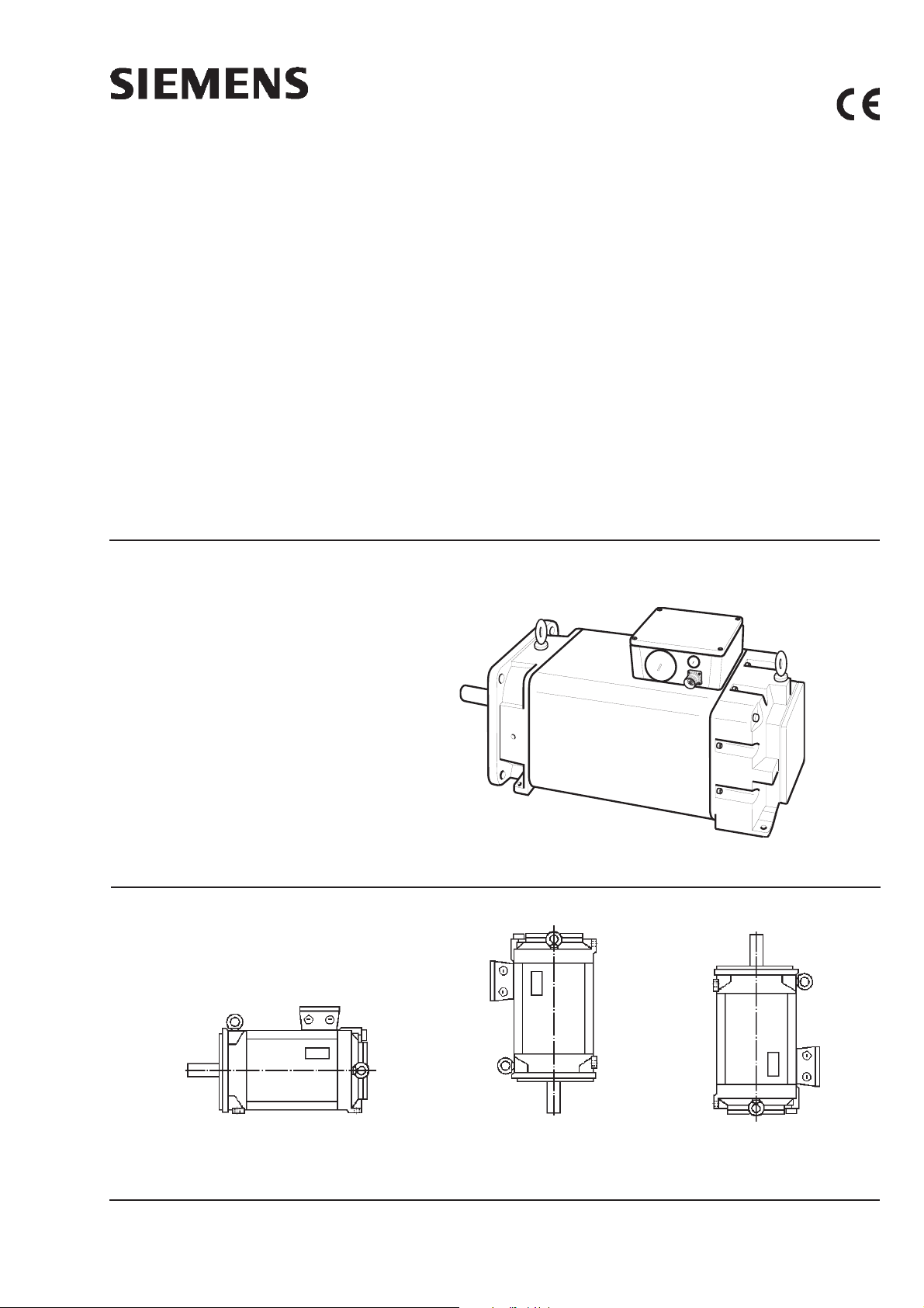
Flüssigkeitsgekühlte Drehstrommotoren für Hauptspindelantriebe
(Beschreibung s. Seite 2)
Liquid-Cooled Three-Phase Motors for Main Spindle Drives
(Description on page 5)
1PH4
Betriebsanleitung
Instructions
Motortypen / Motor types
1PH4 103
1PH4 105
1PH4 107
1PH4 133
1PH4 135
1PH4 137
1PH4 138
IM B 35
1PH4 163
1PH4 167
1PH4 168
Fig. 1 Bauformen / Types of construction
IM V 15
1PH4
IM V 36
Ausgabe / Edition 03.2003
Siemens AG 2003 All Rights Reserved
Bestell-Nr. / Order No.: 610.43093.02.d
DEUTSCH / ENGLISH
1
Page 2
DEUTSCH
Inhalt Seite
Motortypen, Bauformen (Fig. 1) 1
Allgemeiner Hinweis 2
1 Beschreibung
1.1 Anwendungsbereich 2
1.2 Arbeitsweise und Aufbau 2
2 Betrieb
2.1 Transport, Lagern 2
2.2 Aufstellung 2
2.3 Wuchtung, Abtriebselemente 2
2.4 Kühlmittelanschluß 3
2.5 Elektrischer Anschluß 3
2.6 Inbetriebnahme 3
3 Instandhaltung 3
3.1 Temperatursensor 4
3.2 Demontage/Montage der Geber 4
3.3 Lagerwechsel, Schmierung 4
Anhang
Ersatzteile, Normteile 9...
Fig. 2 ...
Allgemeine Hinweise
Zu beachten sind die Angaben und
Anweisungen in allen gelieferten Betriebs- und sonstigen Anleitungen.
Dies ist zur Vermeidung von Gefahren und Schäden unerläßlich!
Eine zusätzliche Sicherheitsinformation (gelb) ist mit eingeheftet.
Weiterhin sind die jeweils geltenden nationalen, örtlichen und
anlagespezifischen Bestimmungen und Erfordernisse zu
berücksichtigen!
Sonderausführungen und Bauvarianten können in technischen Details abweichen! Bei eventuellen Unklarheiten wird dringend empfohlen, unter Angabe von Typbezeichnung und Fabrik-
nummer (No E ... , s. Leistungsschild) beim Hersteller rückzufragen, oder die Instandhaltungsarbeiten von einem der SIEMENSServicezentren durchführenzulassen.
1 Beschreibung
1.1 Anwendungsbereich
Bestimmungsgemäße Verwendung: Die Motoren werden be-
vorzugt dort eingesetzt, wo im Einbauraum für Lüftkühlung ungeeignete Umgebungsbedingungen herrschen, die Umgebung thermisch
nicht belastet werden darf oder eine hohe Leistungsdichte des Motors
bei beschränktem Einbauraum gefordert wird.
Typische Anwendungsfälle sind Fräsmaschinen mit Vollkapselung
und angetriebene Werkzeuge oder Gegenspindeln bei Drehmaschinen.
Technische Merkmale
Standardschutzart IP65 (am Wellendurchtritt IP54)
Kühlmittelzulauftemperatur Wasser: +5° bis +30°C,
andere Kühlmittel bzw. Temperaturen auf Anfrage!
Umgebungstemperatur vor Frost schützen
Meßflächenschalldruckpegel (DIN EN 21 680 Teil 1)
1PH410. bis 1PH413. ca. 69 dB(A)
1PH416. ca. 71 dB(A)
2 Betrieb
2.1 Transport, Lagern
Beim Transport sind alle vorhandenen Hebeösen (Fig. 2) zu benutzen.
Wird ein Motor nach Lieferung nicht gleich in Betrieb genommen, so ist er
in einem trockenen, staub- und erschütterungsfreien Raum zu lagern.
2.2 Aufstellung
Leistungsschildangaben hinsichtlich Bauform und Schutzart beachten
und Übereinstimmung mit den Verhältnissen am Einbauort prüfen!
Eingeschraubte Hebeösen sind nach dem Aufstellen festanzuziehen oder zu entfernen!
Bei Motoren mit Doppellagerung AS ist zu beachten:
- Doppellagerung AS (Standardausführung) ist immer durch eine
Mindestquerkraft zu belasten, s. Querkraftdiagramme 1PH4
Diese Motoren eignen sich nicht für Kupplungsbetrieb! Hierfür muß
Einfachlagerung (Option K00) vorgesehen werden. Besonders hohe
Drehzahlen werden mit der Option L37 ermöglicht.
Zulässige immittierte Schwingungen
Das Systemschwingungsverhalten am Einsatzort, bedingt durch
Abtriebselemente, Anbauverhältnisse, Ausrichtung und Aufstellung
sowie durch Einflüsse von Fremdschwingungen, kann zur Erhöhung
der Schwingwerte am Motor führen. Mit Rücksicht auf eine einwandfreie Funktion des Motors und eine lange Lagerlebensdauer sollen die
angegebenen Schwingwerte in Fig. 8 nicht überschritten werden.
Unter Umständen kann ein komplettes Auswuchten des Läufers mit
dem Abtriebselement erforderlich sein.
2.3 Wuchtung, Abtriebselemente
Das Auf- und Abziehen von Abtriebselementen (z.B. Kupplungsscheibe, Zahnrad, Riemenscheibe, ...) ist grundsätzlich mit geeigneten
Vorrichtungen auszuführen.
Hierzu Gewinde im Wellenende benutzen (s. Fig. 12).
Standardmäßig sind die Läufer mit einer vollen Paßfeder
dynamisch ausgewuchtet. Option L37 wird standardmäßig
ohne Paßfeder ausgeliefert .
HINWEIS: Kennzeichnung der Auswuchtart am Wellenspiegel beach-
ten!
(F = Auswuchtung mit voller Paßfeder)
(H = Auswuchtung mit halber Paßfeder-Sonderausführung)
Bei Montage des Abtriebselementes auf entsprechende Auswuchtart achten!
Auswuchtung mit halber Paßfeder
Bei Abtriebselementen mit einem Längenverhältnis < 0,8 (Nabenlänge l
zur Länge des Wellenendes lM ) und Drehzahlen > 1500/min können
Laufruhestörungen auftreten (s. Fig. 13).
Ggf. ist eine Nachwuchtung vorzunehmen, z. B. ist der aus dem
Abtriebselement und über der Wellenkontur herausragende Teil der
Paßfeder TP abzuarbeiten.
Zu beachten sind die allgemein erforderlichen Maßnahmen für den Berüh-
rungsschutz der Abtriebselemente.
Wird ein Motor ohne Abtriebselement in Betrieb genommen,
so ist die Paßfeder gegen Herausschleudern zu sichern.
Die zulässigen Quer- und Axialkräfte sind den Diagrammen in der
Projektierungsanleitung zu entnehmen (ggf. Anfrage in Zweigniederlassungen oder Herstellerwerk).
1.2 Arbeitsweise und Aufbau
Die 1PH4-Motoren sind wassergekühlte vierpolige Asynchronmaschinen mit Käfigläufer.
- Motoraktivteil mit in der Ständerwicklung eingebautem Temperatur-
sensor zur Erfassung des Temperaturganges der Wicklung, sowie
für die Regelung und als Schutz gegen unzulässige Erwärmung des
Motors. Als Reserve steht ein zweiter in der Ständerwicklung
eingebauter Temperatursensor zur Verfügung (s. 3 Instandhaltung)
- Gebersystem zur Erfassung von Motordrehzahl und relativer
Änderung der Läuferlage (auf der BS eingebaut);
2
2.4 Kühlmittelanschluß
HINWEIS: Für die Flüssigkeitskühlung sind die Absätze 2.2.7.2
Leitungs- und Amaturenwerkstoffe und 2.2.7.7 Elektrische Bauteile
der VDI 3035 Richtlinie zu beachten!
Für den Betrieb der 1PH4-Motoren ist ein geschlossener Kühlmittelkreislauf mit Rückkühlaggregat notwendig. An der B-Seite befinden
sich die Öffnungen für den Kühlmittelanschluß, hierzu sind die zwei
Verschraubungen (6.85-Fig. 2) zu entfernen. Ist die Richtung des
Kühlmittelstroms nicht durch Pfeile gekennzeichnet, so kann die Einbzw. Austrittsöffnung frei gewählt werden.
Siemens AG
Page 3
DEUTSCH
Die Fig. 4 ermöglicht die Ermittlung des zur Einhaltung der spezifizierten
Wellenleistung erforderlichen Kühlwasserstroms und der Kühlleistung
im Bemessungsbetrieb (max. Vorlauftemperatur des Kühlwassers
+30°C), sonst Leistungsminderung. Das Kühlwasser kann mit
Korrosionsschutzmittel versehen sein. Grenzmischung: max. 25%
Korrosionsschutzmittel (z.B. Tyfocor) und 75% Wasser.
Ist, bei bereits gefülltem Kühlkreislauf, mit Frosteinwirkung zu rechnen
muss ein handelsübliches Frostschutzmittel zugemischt werden.
Anwendung un Dosierung nach Herstelllerangaben (max. 50 %).
Mischen verschiedener Frostschutzmittel ist zu vermeiden!
Es sollen möglichst keine Buntmetalle, wie Kupfer- oder Messingleitungen, im Kühlkreislauf verwendet werden (Elektrolytbildung!).
Es ist zweckmäßig, einen Filter einzusetzen, der Partikel mit einer
Korngröße von 100 µm zu 95 Massenprozent zurückhält.
Das Überdruckventil muß nach dem Filter in der Zuleitung eingebaut
sein. Max. zulässiger Druck des Überdruckventil s. Fig. 4 .
2.5 Elektrischer Anschluß
Alle Arbeiten nur im elektrisch spannungslosen Zustand der Anlage
durchführen!
Der Motor ist gemäß dem mitgelieferten Schaltbild anzuschließen. Leistungsschilddaten beachten!
Grundsätzlich ist beim Anschließen zu beachten, daß
- die Anschlußleitungen der Verwendungsart, den auftretenden
Spannungen und Stromstärken angepaßt sind,
- ausreichend bemessene Anschlußleitungen, Verdreh- , Zug- und
Schubentlastung sowie Knickschutz für die Anschlußleitungen
vorgesehen sind und
- der Schutzleiter an angeschlossen ist.
Bei Klemmenkastenanschluß ist zu beachten, daß
- die Leitungsenden nur soweit abisoliert sind, daß die Isolierung
nahezu bis zum Kabelschuh bzw. Klemme reicht
- die Größe der Kabelschuhe an den Abmessungen der Klemmbrettanschlüsse und dem Querschnitt der Netzleitung angepaßt sind,
ggf. ist mit parallelen Anschlußleitungen zu arbeiten
- der Schutzleiter angeschlossen ist
- das Klemmenkasteninnere sauber und frei von Leitungsresten ist
- alle Schraubenverbindungen der elektrischen Anschlüsse -Klemmenbrettanschlüsse (außer Klemmenleisten) nach vorgegebenen Anziehdrehmomenten angezogen sind, s. Fig. 7
- sowohl beim Anschließen wie auch beim evtl. Umsetzen innerer
Verbindungsleitungen ist auf die Einhaltung der Mindestluftstrecken
nach Fig. 6 zu achten
- die Mindestluftstrecken bei nicht isolierten unter Spannung stehender Teile eingehalten sind. Auf abstehende Drahtenden ist zu achten
- unbenutzte Einführungen verschlossen und die Verschlußelemente fest und dicht eingeschraubt sind
- zur Aufrechterhaltung der Schutzart alle Dichtflächen des Klemmenkastens ordnungsgemäß beschaffen sind!
2.5.1 Leistungsanschluß (s. Fig. 5)
Der Leistungsanschluß erfolgt über den Klemmenkasten.
Ein direkter Anschluß an das
Drehstromnetz ist nicht erlaubt und führt
zur Zerstörung des Motors.
Auf richtige Phasenfolge ist zu achten!
Der Motor darf nur mit einem leistungsmäßig abgestimmten Umrichter
betrieben werden.
HINWEIS: Bei den Klemmenkästen von 1PH4 10. müssen die Kabelschuhe der Leistungsanschlüsse direkt auf den Kabelschuhen der
Motorwicklungsanschlüsse zum Liegen kommen.
2.5.2 Impulsgeber und Temperatursensor
Der Anschluß erfolgt über die im Klemmenkasten eingebaute
Flanschdose mit Kontaktstiften.
2.6 Inbetriebnahme
Vorsicht Verbrennungsgefahr!
An den Motoren können hohe Oberflächentemperaturen von über 80°C auftreten.
Es dürfen dort keine temperaturempfindlichen Teile, wie
z. B. normale Leitungen oder elektronische Bauteile,
anliegen oder befestigt werden.
Bei Bedarf Berührungsschutzmaßnahmen vorsehen!
Bei Speisung durch Umrichter können hochfrequente Strom- und
Spannungsoberschwingungen in den Motorzuleitungen zu elektromagnetischen Störaussendungen führen. Deshalb wird die Verwendung abgeschirmter Zuleitungen empfohlen.
Vor Inbetriebnahme ist zu prüfen, ob
- der Läufer ohne anzustreifen gedreht werden kann
- der Motor ordnungsgemäß montiert und ausgerichtet ist
- die Abtriebselemente richtige Einstellbedingungen haben (z. B.
Riemenspannung bei Riementrieb; ...) und das Abtriebselement für
die Einsatzbedingungen geeignet ist
- alle elektrische Anschlüsse sowie Befestigungsschrauben und
Verbindungselemente nach Vorschrift angezogen und ausgeführt
sind
- der Schutzleiter ordnungsgemäß angeschlossen ist
- eventuell vorhandenen Zusatzeinrichtungen (Bremse, ...) funktionsfähig sind
- Berührungsschutzmaßnahmen für bewegte und spannnungsführende Teile getroffen sind
- das Kühlwasser bereits mit der angegebenen Durchlaufmenge
zirkuliert;
- die Grenzdrehzahl n
HINWEIS: Die Grenzdrehzahl n
Betriebsdrehzahl. Es ist zu beachten, daß sich hierbei das Geräuschund Schwingungsverhalten des Motors verschlechtert sowie die
Lagerwechselfrist verringert.
Die Haltebremse ist nur für eine begrenzte Anzahl von
Notbremsungen ausgelegt.
Der Einsatz als Arbeitsbremse ist nicht zulässig.
Diese Aufzählung kann nicht vollständig sein. Zusätzliche
Prüfungen sind gegebenenfalls nötig!
(s. Leistungsschild) nicht überschritten wird
max
ist die höchste kurzzeitig zulässige
max
Nach dem Anbau der Motoren ist die
ein- oder angebaute Bremse (falls
vorhanden) auf ihre einwandfreie
Funktion zu prüfen!
3 Instandhaltung
Sicherheitsmaßnahmen
Vor Beginn jeder Arbeit an der
Anlage, besonders aber vor dem
Teile, muß der Motor vorschriftsmäßig freigeschaltet
sein. Neben den Hauptstromkreisen ist dabei auch auf
eventuell vorhandene Zusatz- oder Hilfsstromkreise zu
achten.
Die üblichen "5 Sicherheitsregeln" lauten hierbei z. B.
nach DIN VDE 0105:
- Freischalten
- Gegen Wiedereinschalten sichern
- Spannungsfreiheit feststellen
- Erden und Kurzschließen
- Benachbarte unter Spannung stehende Teile abdecken
oder abschranken
Diese zuvor genannten Maßnahmen dürfen erst dann
zurückgenommen werden, wenn die Instandhaltungsarbeiten abgeschlossen sind und der Motor vollständig
montiert ist.
Öffnen von Abdeckungen aktiver
Siemens AG
3
Page 4
DEUTSCH
3.1 Temperatursensor
Bei Ausfall des Temperatursensors kann durch Umklemmen im
Klemmenkasten auf den als Reserve eingebauten zweiten Temperatursensor umgeschaltet werden.
Dazu Schaltbild im Klemmenkasten beachten!
3.2 Demontage / Montage der Geber
Vorsicht! Gebersysteme mit integrierter Elektronik (optische Geber, Rotorlagegeber, Zahnradgeber, ...) sind elektrostatisch gefährdete
Bauelemente und Baugruppen (EGB).
Bei Arbeiten an EGB-Bauelementen ist zu beachten, daß
- der Arbeitsplatz geerdet ist
- ein direktes Anfassen der Steckerpins vemieden wird
- beim Berühren keine elektrostatische Ladung übertragen wird
(unmittelbar vor Berührung leitfähigen Gegenstand anfassen,...)
- beim Transport geeignete Verpackung verwendet wird (Schachtel
aus Wellpappe, leitfähige Kunststoffbeutel - keine normalen
Kunststoffbeutel, kein Styropor, ...);
Hinweis zur Geberdemontage/ -montage
- Deckel demontieren / montieren
- ggf. mit Hilfe einer Rundlauf-Meßuhr muß am Gebergehäuse überprüft werden, ob der radiale Ausschlag bei einer Umdrehung des
Motorläufers kleiner, als der in den jeweiligen Fig. (ROD 431.001/ERN
1381- Fig. 2) angegeben ist. Wenn dieser Wert überschritten wird,
Gebersystem nochmals demontieren, die Kegelflächen reinigen und
das Gebersystem gut fluchtend wieder montieren;
3.2.1 Demontage / Montage ERN1381und ROD 431.001
(8.50 - Fig. 2) und Fig. 3.1
Demontage
- Schraube 1 am Geber herausschrauben und Deckel entfernen
- Stecker mit Signalsteckerleitung abziehen
- Schrauben (8.57) und Schraube (8.51) herausdrehen, ggf. Mitdrehen des Motorläufers verhindern
- Gewindestift (s. Fig. 3.2) zum Schutz der Zentrierung in das
Wellenende einschrauben und das Geber durch Eindrehen einer
Schraube abdrücken;
Montage
- Drehmomentstütze (8.52) mit Schrauben (8.53) an Geber anschrauben (Abstand zwischen Drehmomentstütze und Geber beachten) und Schrauben sichern, z. B. mit Loctite 243
- Geber mit montierter Drehmomentstütze auf den Konus des Motorläufers aufsetzen und Schraube (8.51) eindrehen, max. Anziehdrehmoment beachten, ggf. Mitdrehen des Motorläufers verhindern
- Drehmomentstütze mit den Schrauben (8.57) befestigen, radialer
Ausschlag am Geber beachten
- Metallhülse an Signalsteckerleitung in Deckel eindrücken
- Stecker einstecken, Steckerbeschriftung "TOP" bzw. Nase nach
innen
- Deckel anschrauben;
3.3 Lagerwechsel, Schmierung
3.3.1 Lagerwechselfrist
HINWEIS: Bei der Motorlagerung ist zwischen Doppellagerung AS,
Einfachlagerung AS und Lagerung für hohe Drehzahlen (L37) zu
unterscheiden!
Bei Dauerbetrieb sollte 75% der Grenzdrehzahl n
schild) nicht überschritten werden.
Bei normalen Betriebsbedingungen werden für die Lager der
1PH4-Motoren Lagerwechselfristen tLW nach Fig. 9 empfohlen.
Die angegebenen Betriebsstunden gelten für waagrechte Einbaulage, Kühlmitteltemperaturen von +20°C, Lagertemperaturen von
+85°C, und Schwingungen gemäß der Schwingstärkestufe R nach
DIN VDE530 Teil 14. Die mittlere Betriebsdrehzahl nm ist bei wechselnden Motordrehzahlen abzuschätzen.
(s. Leistungs-
max
Bei besonderen Betriebsbedingungen, z. B. senkrechter
Motoreinbaulage, bei überwiegenden Betrieb oberhalb von 75% der
Grenzdrehzahl n
häufigem Reversierbetrieb, ... reduzieren sich die Lagerwechselfristen
t
bis zu 50%.
LW
Treten dauernd höhere Lagertemperaturen als +85°C auf, ist die
Lagerwechselfrist pro 15°C Temperaturerhöhung zu halbieren.
Nach den angegebenen Betriebsstunden wird empfohlen,
die Lager AS und BS zu erneuern, jedoch spätestens nach 5
Jahren.
Bei eingegelagertem Geber wird empfohlen diesen ebenfalls zu
erneuern, um einen Ausfall des Gebers zu vermeiden.
, großen Schwingungs- und Stoßbelastungen,
max
3.3.2 Demontage / Montage des Motors
Bei Demontage ursprüngliche Lage der Teile zu einander markieren (z.
B. mit Farbstift, Reißnadel), um die spätere Montage zu vereinfachen.
Restliches Kühlwasser aus Motor ablaufen lassen.
Geberdemontage s. 3.2. Lagerdeckel- und Lagerschildschrauben auf
der AS-Seite herausdrehen, danach AS-Lagerschild vorsichtig abnehmen. Läufer aus dem Motorständer herausziehen. Wälzlager mit
geeigneter Vorrichtung abziehen (s. Fig. 10.1).
HINWEIS: Beim Lagerwechsel ist auf die Anordnung der Deckscheibe
zu achten!
Abgezogene Wälzlager nicht wieder verwenden. Wälzlager aufschieben, dabei muß sichergestellt sein, daß der Lagerinnenring an
der Wellenschulter bündig anliegt! AS-Lagerschild und Gehäuse
von Dichtmittelrückständen befreien. Dichtflächen mit Terostat 93
oder gleichwertigen Dichtmittel bestreichen. Läufer in das Gehäuse
einführen. AS-Lagerschild ohne zu verkanten in das Motorgehäuse
einsetzen. Lagerdeckelschrauben anziehen. AS-Lagerschild festschrauben. Gebersystem montieren.
Es wird empfohlen, Dichtelemente, z. B. Radialwellendichtring (Fig.
11), gleichzeitig zu erneuern.
Für die Montage der Schraubverbindungen gelten die Anziehdrehmomente nach Fig. 7.
3.3.3 Doppellagerung AS (Standardausführung)
- Zylinderrollenlager (1.70) mit Rillenkugellager (1.60-Fig. 2)
HINWEIS: Es wird empfohlen, Zylinderrollenlager im Herstellerwerk
nachzubestellen, damit Besonderheiten wie z. B. Lagerluft berücksichtigt werden.
Lagerwechsel, Schmierung
Die Fettvorratsräume (z. B. im Lagerschild, Lagerdeckel) sind mit der
angegebenen Fettsorte bis zur Hälfte (s. Fig. 10.2) zu füllen.
Fettmenge pro Lager (s. Fig. 9.2 - Rillenkugellager und Zylinderrollenlager)
Das Fett ist gleichmäßig in der Laufbahn zu verteilen.
Wälzlager gleichmäßig auf ca. 80 - 100°C erwärmen und aufschieben.
Harte Schläge (z. B. mit einem Hammer, ...) sind zu unterlassen.
Fettsorte
UNIREX N3 (Fa. ESSO); Ersatzfette müssen DIN 51825/K3N genügen.
Lagereinlauf
Nach dem Lagerwechsel sollen die Lager einlaufen, damit sich das
Fett gleichmäßig verteilen kann. Hierbei sollten erstmalig die Motoren
kontinuierlich von 0 bis ca . 75% der Grenzdrehzahl n
20 Minuten hochgefahren werden.
innerhalb von
max
3.3.4 Einfachlagerung AS
(Option K00, K02 oder K03 s. Leistungsschild)
- Rillenkugellager (1.60 - Fig. 2).
Lagerwechsel, Schmierung, Fettsorte und Lagereinlauf s.
Abschnitt 3.3.3 .
Fettmenge pro Lager (s. Fig. 9.2 - Rillenkugellager)
4
Siemens AG
Page 5

DEUTSCH
ENGLISH
3.3.5 Lagerung für hohe Drehzahlen
(Option L37 s. Leistungsschild)
Wuchtung
Motoren mit Lagern für hohe Drehzahlen sind halbkeilgewuchtet.
Lagerwechsel, Schmierung
Es ist auf höchste Sauberkeit zu achten!
Die Fettvorratsräume (z. B. im Lagerschild, Lagerdeckel) sind mit der
angegebenen Fettsorte bis zur Hälfte (s. Fig. 10.2) zu füllen.
Lager vor dem Fetten nicht auswaschen!
Lager mit angegebener Fettmenge füllen, hierbei ist das Fett gleichmäßig in der Laufbahn zu verteilen.
Fettmenge pro Lager (s. Fig. 9.2 - Lager für hohe Drehzahlen)
Fettsorte
LUBCON THERMOPLEX 2TML (Fa. Lubricant Consult)
Montage
Die Lager sind induktiv auf 80°C, max. 100°C zu erwärmen und auf den
gesäuberten, staubfreien Lagersitz aufzuschieben.
Beim Montieren der Lagerdeckel ist darauf zu achten, daß die
Dichtungen ihre Dichtfunktion noch gewährleisten können. Ansonsten sind sie durch neue zu ersetzen!
Lagereinlauf unter s. Abschnitt 3.3.3
General notes
The information and instructions given in
all the operating instructions and other
instructions supplied with the equipment
must be followed. This is essential in order to avoid danger and
damage!
A supplementary safety bulletin (yellow) is included.
Any relevant national, local or system-specific regulations
and requirements must also be taken into account!
Special and modified versions may differ with regard to technical
details! If anything is unclear, you are urged to contact the
manufacturer, quoting the type designation and serial number (No.
E ..., see rating plate) or to have the repair work carried out by a
Siemens service centre.
1 Description
1.1 Application range
Usage to the intended purpose: The 1PH4 motors are used
primarily for installation in spaces where the surrounding conditions
are unfavourable for air-cooling, where the environment must not be
subjected to heat or where high power density of the motor is required
in a limited space.
Typical applications are completely enclosed milling machines with
power tools or reverse spindles on lathes.
ENGLISH
Contents Page
Motor types / Types of construction (Fig. 1) 5
General notes
1 Description 5
1.1 Application range 5
1.2 Mode of operation and design 5
2 Operation 5
2.1 Transport, storage 5
2.2 Installation 5
2.3 Balancing, output elements 6
2.4 Coolant connection 6
2.5 Electrical connections 6
2.6 Start-up 6
3 Repair 7
3.1 Temperature sensor 7
3.2 Disassembly/assembly of the encoders 7
3.3 Changing bearings, lubrication 8
Technical characteristics
Standard type of protection IP65 (at the shaft exit IP54)
Coolant supply temperature Water: + 5° to + 3•°C, other coolants
or temperatures on request!
Ambient temperature Protect against frost
Measuring-surface sound-pressure level
(DIN EN 21 680 Part 1)
1PH410. to 1PH413. Approx. 69 dB(A)
1PH416. Approx. 71 dB(A)
1.2 Mode of operation and design
1PH4 motors are water-cooled, four-pole asynchronous motors with
squirrel-cage rotors.
- Core-and-winding assembly with a temperature sensor
integrated in the stator winding for measuring the temperature
response of the latter, as well as for regulation and preventing the
motor from overheating.
A second, redundant temperature sensor is also provided in the
stator winding (see 3 Repair),
- Encoder system for measuring the motor speed and the relative
change in the rotor position (installed at the ND-end),
2 Operation
2.1 Transport, storage
All the lifting eye-bolts provided (Fig. 2) should be used during
transport. If the motor is not started up immediately on delivery, it must
be stored in a dry room where it is safe from dust and vibrations.
Appendix
Spare parts, standard parts
Fig. 2 ... 9...
Siemens AG
2.2 Installation
Always heed the rating plate markings concerning the type of
construction and the protection class, and verify their conformance
with the conditions on the actual installation site!
If the lifting eye-bolts have been screwed in, they must be either
tightened or removed after the motor has been installed!
For motors with a double DE bearing please note that:
- The double DE bearing (standard design) must always be kept under
a minimum transverse load - see transverse load diagram 1PH4
5
Page 6

ENGLISH
These motors are not suitable for coupled operation! The single
bearing (option K00) must be used for this type of operation. Very high
speeds can be achieved with option L37.
Permissible vibrations
The site vibration response of the system, which is determined
by the output elements, the mounting conditions, the alignment, the
installation and the effects of external vibrations, may cause the
vibration values at the motor to increase. In the interests of reliable
motor operation and a long bearing service life, the vibration values
specified in Fig. 8 should not be exceeded. Under certain circumstances,
the rotor may need to be fully balanced with the output element.
2.3 Balancing, output elements
Suitable devices should always be used to push on or pull off the
output elements (e.g. the coupler disk, gear wheel or belt pulley).
The thread in the end of the shaft should be used for this purpose (see
Fig. 12).
In the standard design, the rotors are dynamically balanced
with a full feather key. Option L37 is normally supplied
without a feather key.
NOTE: The balancing method is marked on the shaft end face!
(F = Balancing with full featherkey)
(H = Balancing with half featherkey - special version)
When the output element is assembled, be careful to use the
correct balancing method!
Balancing with half featherkey
If the output elements have a length ratio < 0.8 (hub length l to shaft end
length lM) and a speed > 1500/min, a certain imbalance may be
noticeable (see Fig. 13).
A re-balancing procedure is necessary in this case, for example the
part of the featherkey TP which protrudes out of the output element and
projects beyond the contour of the shaft must be reduced.
The usual measures should be taken
to guard output elements from touch.
If a motor without output elements is started up, the featherkey
must be prevented from being spun out.
The permissible transverse and axial forces are shown on the graphs
in the Project Planning Instructions (please ask your Regional Office or
the manufacturer for further details if necessary).
2.4 Coolant connection
NOTE: For liquid cooling, sections 2.2.7.2 Materials for Pipes and
Fittings and 2.2.7.7 Electrical Components of the guideline VDI 3035
are to be taken into account.
For operation of the 1PH4 motors, a closed coolant circuit with a heatexchanging unit is necessary. On the ND-end, there are holes for
connecting the coolant supply. The two threaded joints here (6.85 Fig.
2) are to be removed. If the direction of the coolant flow is not marked
by arrows, either of the two holes can be selected as the inlet and the
other as the outlet.
Fig. 4 makes it possible to determine the flow rate of cooling water and
the cooler efficiency needed in order to adhere to the to the specified
shaft output during rated operation (max. inlet temperature of the
cooling water + 30°C), otherwise there will be a decrease in
performance. Anti-corrosion agent can be added to the water.
Mixture: max. 25% anti-corrosion agent (e.g. Tyfocor) and 75%
water. If the cooling circuit has been filled and frost can be expected,
a commercially available antifreeze agent must be added. Please refer
to the manufacturer's documentation for usage and dosage (max. 50
%). Do not mix different types of antifreeze.
If possible no non-ferrous metals such as copper or brass piping may
be used for the cooling circuit (formation of electrolyte!). It is
recommended that a filter be used which traps up to 95 per cent of
particles with a size of 100 µm. The pressure-relief valve must be fitted
after the filter in the cooling circuit. For the maximum permissible
pressure at the pressure-relief valve, see Fig. 4.
2.5 Electrical connections
Do not carry out any work unless the
system is dead!
Connect the motor in accordance with the enclosed circuit
diagram. Note the markings on the rating plate!
General connection instructions:
- The connecting leads must be suitable for the type of application and
for the anticipated currents and voltages,
- The connecting leads, the strain relief device and the devices which
protect against rotation and transverse forces must be adequately
dimensioned, and the connecting leads must be prevented from
kinking,
The PE conductor must be connected to .
Instructions for connecting the terminal box:
- The ends of the leads must not be stripped farther than necessary,
i.e. the insulation must extend almost up to the cable lug or the
terminal,
- The size of the cable lugs must be matched to the dimensions of the
terminal board connections and the cross-section of the mains
cable; if necessary, the connecting leads must be laid parallel,
- The PE conductor must be connected,
- The inside of the terminal box must be kept clean and free from cable
residues,
- All the screws and bolts of the electrical connections on the terminal
boards (but not the terminal blocks) must be tightened to the specified
torques (see Fig. 7),
- The minimum clearances in air specified in Fig. 6 must be observed,
both when connecting and when re-arranging internal connecting
leads,
- The minimum clearances in air must be observed for live, noninsulated parts. Attention must be paid to protruding wire ends,
- Any entries which are not in use must be sealed and the sealing
elements screwed in firmly and tightly,
- All the sealing surfaces of the terminal box must be in good condition,
to ensure that the requirements of the protection class are satisfied!
2.5.1 Power connection (see Fig. 5)
The power must be connected via the terminal box.
The three-phase system must never be
connected directly, since this will cause
the motor to be damaged beyond repair.
The correct phase sequence is vital!
The motor must always be operated with a converter with a suitable
power output.
NOTE: The cable lugs of the power terminals must rest directly on
the cable lugs of the motor winding terminals in the terminal boxes of
the 1PH4 10. motors.
2.5.2 Pulse encoder and temperature sensor
The pulse encoder and the temperature sensor are connected by
means of the flange-mounted connector with pins integrated in the
terminal box.
2.6 Start-up
Caution - high temperatures!
High temperatures in excess of 80 °C may occur
on the motor surfaces.
No temperature-sensitive parts, such as ordinary leads or
electronic components, must be touching or fixed to
these surfaces.
Protection must be provided against electric shock and
moving parts if necessary!
6
Siemens AG
Page 7

ENGLISH
If the motor is supplied by means of converters, high-frequency
current and voltage harmonics in the motor supply leads can cause
electromagnetic interference to be emitted. Screened supply leads
are therefore recommended.
The following checks must be carried out prior to start-up:
- The rotor must be able to turn freely,
- The motor must be properly assembled and aligned,
- The output elements must be set correctly (e.g. belt tension of belt
drive) and be suitable for the intended field service conditions,
- All the electrical connections, the fixing screws and the connecting
elements must be designed and tightened in accordance with the
specified values,
- The PE conductor must be properly connected,
- Any supplementary devices (e.g. a brake) must be operational,
- Protection must be provided against electric shock for moving and
live parts,
- The cooling water is already circulating at the specified flow rate,
- The limit speed n
NOTE: The limit speed n
operating speed. It should be noted that the noise characteristics and
vibration response of the motor deteriorate as a result and that the
bearing replacement intervals are shortened.
functioning correctly!
The holding brake is only designed for a limited number of
emergency braking operations.
It is not allowed to be used as a working brake.
This list of instructions makes no claims to completeness.
Other checks may also be necessary under certain
circumstances!
(see rating plate) must not be exceeded,
max
The holding brake (if any) must be
checked after the motors have been
mounted, to ensure that it is
is the maximum permissible peak
max
3.2 Disassembly/assembly of the encoders
Caution! Encoder systems containing integrated
electronics (optical encoders, rotor position
encoders, gear wheel encoders, etc.) are
electrostatically sensitive components (ESDs).
The following rules must be observed when
working on ESDs:
- The place of work must be earthed,
- The connector pins must not be touched directly,
- No electrostatic charge must be transferred on contact (a
conductive object should be touched immediately before such
contact is made, for example),
- Suitable packaging must be used for transport (corrugated
cardboard boxes, conductive plastic bags - not ordinary plastic
bags, polystyrene, etc.).
Instructions for disassembling/assembling the encoders
- Remove/fit the cover,
- If necessary, secure a concentricity dial gauge to the encoder
casing and check whether the radial runout is less than the value
specified in the diagram (ROD431.001 / ERN 1381- Fig. 2) when the
rotor of the motor is turned one revolution. If this value is exceeded,
disassemble the encoder system again, clean the tapered surfaces
and reassemble the system, making sure it is properly aligned,
3.2.1 Disassembly/assembly of ERN1381 and
ROD 431.001 (8.50 - Fig. 2 and Fig. 3.1)
Disassembly
- Undo the screw 1 in the encoder and remove the cover,
- Remove the connector with the signal connector lead,
- Undo the screws (8.57) and the screw (8.51); the motor rotor must
be prevented from turning at the same time,
- Fit a grub screw (see Fig. 3.2), into the end of the shaft to protect the
centring bore and force off the encoder by inserting a screw .
3 Repair
Safety precautions
The motor must be isolated in
accordance with standards prior to
carrying out any work on the system,
and especially before opening the covers of the core-andwinding assemblies. Any auxiliary circuits must be isolated
in addition to the main circuits.
The usual "5 rules of safety" apply, e.g. as set out in DIN
VDE 0105:
- Isolate,
- Prevent from restarting,
- Verify isolation from supply,
- Earth and short-circuit,
- Cover or safeguard any neighbouring live parts.
These measures must not be reversed until all the repair
work has been completed and the motor fully assembled.
3.1 Temperature sensor
If the temperature sensor fails, it is possible to switch over to the
second (redundant ) temperature sensor by reversing the connections
in the terminal box.
Note the circuit diagram inside the terminal box!
Assembly
- Screw the torque arm (8.52) to the encoder with the screws (8.53)
(leaving a sufficient distance between the torque arm and the
encoder) and lock the screws, e.g. with Loctite 243,
- Position the encoder and the assembled torque arm on the taper of
the motor rotor and insert the screw (8.51); the motor rotor must be
prevented from turning at the same time. Note the maximum tightening
torque,
- Fasten the torque arm with the screws (8.57) and note the radial
runout on the encoder,
- Press the metal sleeve on the signal connector lead into the cover
- Plug in the connector with the word „TOP“ or nose facing inwards,
- Screw on the cover.
3.3 Changing bearings, lubrication
3.3.1 Bearing replacement intervals
NOTE: Motor bearing types are subdivided into double D-end bearings,
and single D-end bearings driven motors!
75 % of the limit speed n
during continuous operation.
Under normal operating conditions, the replacement intervals t
specified in Fig. 9 are recommended for the bearings of the 1PH4
motors.
The specified operating hours apply to a horizontal position, a coolant
temperature of +20 °C, a bearing temperature of +85 °C and vibrations
in accordance with vibration severity grade R (DIN VDE 530 Part 14).
The mean operating speed nm must be estimated if the motor speed
varies.
Under abnormal conditions, e.g. a vertical position, operating
speed mostly above 75 % of the limit speed n
impact loads, frequent reversing, etc., the bearing replacement
intervals tLW must be reduced by up to 50 %.
(see rating plate) must not be exceeded
max
, severe vibration and
max
LW
Siemens AG
7
Page 8

ENGLISH
If the bearing temperature exceeds +85 °C for a prolonged period of
time, the bearing replacement intervals must be halved for each
additional 15 °C.
Renewal of the D-end and ND-end bearings is recommended
after the specified number of operating hours, and at the
latest after 5 years.
We also recommend replacing a self-fitted encoder in order to avoid
the encoder breaking down.
3.3.2 Disassembly/assembly of the motor
When disassembling the motor, mark the original positions of the parts
in relation to one another (e.g. with a marker pen or a drawing pin), in
order to simplify the re-assembly procedure.
Allow the remaining cooling water to drain out of the motor.
Please refer to section 3.2. for the encoder disassembly procedure.
Undo the screws in the bearing cover and the D-end shield, then
carefully remove this shield. Pull the rotor out of the motor. Pull off the
rolling contact bearings using a suitable device (see Fig. 10.1).
NOTE: Take care not to alter the position of the side plate when
replacing the bearings!
Do not re-use the rolling contact bearings after they have been pulled
off. Push on the new bearings, making sure that the inner ring is flush
with the shaft shoulder! Remove all remaining sealing agents from the
D-shield and the housing. Coat the sealing surfaces with Terostat 93
or an equivalent sealing agent. Position the rotor inside the casing. Fit
the D-end shield into the motor casing without canting it. Tighten the
screws in the bearing cover. Screw the D-end shield tight. Assemble
the encoder system.
It is advisable to renew the sealing elements, e.g. the radial shaft seal
(Fig. 11), at the same time.
The screws and bolts must be tightened to the torques specified in
Fig. 7.
3.3.3 Double D-end bearings (standard version)
- Cylindrical-roller bearing (1.70) with deep-groove ball bearing (1.60
- Fig. 2)
NOTE: It is advisable to re-order cylindrical-roller bearings from the
manufacturer, so that account can be taken of any peculiarities, such
as the bearing clearance.
be run up continuously from 0 to approximately 75 % of the limit speed
n
within a period of 20 minutes.
max
3.3.4 Single D-end bearings
(Option K00, K02 or K03, see rating plate)
- Deep-groove ball bearing (1.60 - Fig. 2)
Changing bearings, lubrication, grease type and bearing runin: see section 3.3.3.
Grease quantity per bearing: see Fig. 9.2 - Deep-groove ball
bearing)
3.3.5 Arrangement of the bearings for high speeds
(Option L37 see rating plate)
Balancing
Motors with high-speed bearings are balanced with half-wedges.
Replacing bearings, lubrication
Ensure that the utmost cleanliness is maintained.
The grease reservoirs (e.g. bearing plate, bearing cover) are to be
half-filled with the types of lubricants stated (see fig. 10.2).
Do not wash the bearing out before lubricating!
Fill the bearing with the stated quantity of lubricant, ensuring that the
lubricant is evenly distributed in the track.
Quantity of lubricant per bearing (see fig. 9.2 - High-Speed
Bearings)
Types of lubricants
LUBCON THERMOPLEX2TML (Lubricant Consult Co.)
Assembly
Heat the bearings inductively to 80°C, max. 100°C, and slide them onto
the cleaned, dust-free bearing seating.
When mounting the bearing plate, ensure that the seals are still capable
of performing their sealing function, otherwise they must be replaced
by new ones.
Running in the bearings: see section 3.3.3
Changing bearings, lubrication
The sealing grease compartments (e.g. in the end shield and bearing
cover) must be filled half full with the specified grease type (see Fig.
10.2).
Grease quantity per bearing (see Fig. 9.2 - Deep-groove ball
bearing and cylindrical-roller bearing)
The grease must be evenly distributed around the raceway.
Heat the rolling contact bearings uniformly to approximately 80-100 °C
and push them on. Be careful not to knock them too hard (e.g. with a
hammer).
Grease type
UNIREX N3 (from ESSO); alternative greases must conform to DIN
51825/K3N.
Bearing run-in
After the bearings have been replaced, they should be run in, to
ensure that the grease is evenly distributed. The motors should initially
8
Siemens AG
Page 9

ANHANG / ANNEX
DEUTSCH
Ersatzteile (Fig. 2 ... Fig. 2.2),
vom Werk lieferbar (siehe Bestellbeispiel)
1.00 Lagerung AS
.41 Lagerschild IM B 35
.42 Radialwellendichtring
.43 Hülse
.44 Dichtring
.45 Hülse
.46 O-Ring
.48 Schraube
.49 Dichtscheibe
.60 Wälzlager
.70 Wälzlager
.95 Lagerdeckel, innen
3.00 Läufer, komplett
.10 Läufer
4.00 Ständer, komplett
.10 Gehäuse mit Paket
.11 Leistungsschild
5.00 Klemmenkasten, komplett
.10 Dichtung
.11 Klemmenkastenoberteil
.12 Dichtung
.13 Klemmkastendeckel
.20 Klemmenbrett, vollständig
.21 Zwischenstück
.22 Klemmleiste
.24 Bügel
.25 Klemmbügel
.35 Schraube
6.00 Lagerung BS
.10 Wälzlager
.20 Lagerschild BS
.22 Federscheibe
.83 Deckel
.84 Dichtung
.85 Verschlußschraube
.90 O-Ring
ENGLISH
Spare parts (Fig. 2 ... Fig. 2.2), available from
the manufacturer (see order example)
1.00 Drive-end bearing
.41 Endshield IM B 35
.42 Radial shaft seal
.43 Sleeve
.44 Seal
.45 Sleeve
.46 O-ring
.48 Screw
.49 Seal
.60 Rolling contact bearing
.70 Rolling contact bearing
.95 Inside bearing cover
3.00 Rotor, complete
.10 Rotor
4.00 Stator, complete
.10 Casing with core assembly
.11 Rating plate
5.00 Terminal box, complete
.10 Gasket
.11 Terminal box top section
.12 Gasket
.13 Terminal box cover
.20 Terminal board, complete
.21 Spacer
.22 Terminal block
.24 Clip
.25 Terminal clip
.35 Terminal screw
6.00 Non-drive end bearing
.10 Rolling contact bearing
.20 Non-drive endshield
.22 Spring washer
.83 Cover
.84 Seal
.85 Screw plug
.90 O-ring
Normteile sind nach Abmessung, Werkstoff und
Oberfläche im freien Handel zu beziehen.
Standard commercially available parts are to be
purchased in accordance with the specified dimensions, material and surface finish.
1.98
6.98
DIN 125
DIN 433
DIN 9021
5.14
DIN 128
5.18
5.34
1.99
DIN 580
6.99
1.48
1.50
4.19
5.17
5.19
5.29
5.34
6.52
6.53
6.54
6.56
6.59
6.87
8.59
DIN 912
DIN 6912
DIN 7971
5.37
5.39
DIN 7985
6.29
1.97
(1PH4 10.)
DIN 934
8.00 Einbauten
.50 ERN 1381.001 / ROD431.001
.51 Schraube
.52 Drehmomentstütze
.53 Schraube
.54 Flanschstecker
.57 Kombischraube
Bestellbeispiel:
Ordering example:
8.00 Built-in components
.50 ERN 1381.001 / ROD431.001
.51 Screw
.52 Torque arm
.53 Screw
.54 Flange connector
.57 Screw with washer assembly
1PH4 131-4CF 40 - 0AA01
Nr. E 6K 6 76353 01 005
1.41 Lagerschild IM B 35
3.11
5.42
DIN 6885
DIN 7603
DIN 46320
Lagertyp: DIN 625
1.60
Type of bearing
6.10
Lagertyp: DIN 5412
1.70
Type of bearing
5.43 DIN 46320
Siemens AG
9
Page 10

DEUTSCH / ENGLISH
Anzugsmomente nach Fig. 7
10
Fig. 2 1PH4 IM B 35
Siemens AG
Page 11

DEUTSCH / ENGLISH
1PH4 10. / gk 233
5.21 5.39
5.35 5.255.34
ohne / without 5.13
5.22
5.25
5.35
5.34
ERN1381/ROD431.001
Resolver Size 21
1PH4 13. / gk 433
5.20
5.22
5.37
5.10
5.29
5.14
5.11
5.24
5.17 5.12
5.43
5.18
5.19
5.13
5.23
5.42
Fig. 2.5 Klemmenkasten / Terminal box
3.1 Demontage ERN 1381/ROD431.001/
EQN 1325.001
1. Schrauben (6.87, Fig. 2) abschrauben und Deckel (6.83, Fig. 2)
abnehmen.
Geber ist elektrostatisch gefährdet!
Sicherungsmaßnahmen treffen!
2. Schrauben (1, Fig. 3.2) am Geberdeckel (Kabeleingang) ab-
schrauben.
3. Geberdeckel abnehmen.
4. Mittelschraube (2, Fig. 3.2) zur Befestigung des Gebers an der
Motorwelle herausschrauben, dabei Motorwelle gegenhalten.
5. Schrauben (3, Fig. 3.2) der Drehmomentstütze (4, Fig. 3.2)
abschrauben.
6. Gewindestift (6, Fig. 3.2), DIN913-M5x20, einschrauben.
7. Geber durch Einschrauben der Schraube (5, Fig. 3.2), M6x70, von
der Motorwelle abdrücken.
3.1 Disassembling the ERN 1381/ROD431.001/
EQN 1325.001
1. Unscrew the screw (6.87, Fig. 2) and remove the cover
(6.83, Fig. 2).
The transducer can be damaged by electrostatic charges.
Take safety precautions.
2. Unscrew the screw (1, Fig. 3.2) on the transductor cover (cable
inlet).
3. Remove transductor cover.
4. Hold the motor shaft still and screw out the centre screw (2, Fig. 3.2)
which fixes the transductor to the motor shaft.
5. Unscrew the screws (3, Fig. 3.2) on the holding plate (4, Fig. 3.2).
6. Screw in the threaded pin (6, Fig. 3.2), DIN913-M5x20.
7. Pull the transductor off the motor shaft by screwing in the screw
(5, Fig. 3.2), M6x70.
Siemens AG
11
Page 12

DEUTSCH / ENGLISH
8. Stecker Geberanschluß abziehen. Geber (7, Fig. 3.2) abziehen
und ablegen.
9. Schraube (5, Fig. 3.2) und Geberstift (6, Fig. 3.2) entfernen.
Statt Gewindestift (6, Fig. 3.2) und Schraube (5, Fig. 3.2)
kann folgende Sonderschraube verwendet werden
(nicht im Lieferumfang)!
42
3
1
Fig. 3.2: Abdrücken des Gebers mit Gewindestift
und Schraube oder Sonderschraube
1 Schraube zur Deckelbefestigung
2 Mittelschraube zur Befestigung Geber
3 Schraube zur Befestigung Drehmomentstütze
4 Drehmomentstütze
5 Abdrückschraube
6 Gewindestift
7 Geber
8. Pull the plug out of the transducer connector. Draw the transducer
off (7, Fig. 3.2) and lay it down.
9. Remove the screw (5, Fig. 3.2) and the threaded pin
(6, Fig. 3.2).
Instead of the threaded pin (6, Fig. 3.2) and the
screw (5, Fig. 3.2), the following special screw can be
used (not within the scope of the delivery)!
5
6
Fig. 3.2: Pulling off the transducer with the
threaded pin and screw or special screw
1 Centre screw for holding transducer
2 Central screw holding the transductor
3 Screw fixing the holding plate
4 Holding plate
5 Pulling-off screw
6 Threaded pin
7 Transducer
7
6
Fig. 3.3: Sonderschraube für Demontage
Typ
Type
1PH410.
1PH413.
1PH416.
ERN 1381.001 und ROD 431.001
Kühlwasserstrom
Cooling water flow rate
± 0,75 I/min
6 I/min
6 I/min
6 I/min
8 I/min
8 I/min
8 I/min
8 I/min
10 I/min
10 I/min
10 I/min
M 6 Ø 4 m m
> 1 0 m m
1 0 0 m m
Kühlleistung
Cooler efficiency
1900 W
2600 W
3000 W
2750 W
3500 W
4100 W
4500 W
4600 W
5400 W
6200 W
5 6 m m
Fig. 3.3: Special screw for disassembling the
ERN 1381.001 and ROD 431.001
Anschluß
Connection
G 1/4
G 3/8
G 1/2
max. zulässiger Druck
Maximum permissible
pressure
3 bar
Fig. 4 Kühlmittelanschluß / Coolant connection
12
Siemens AG
Page 13

DEUTSCH / ENGLISH
Typ / Type
Motorklemmenkasten
Motor terminal box
Anzahl x Größe
Quantity x Size
für Leiterquerschnitt max. mit Kabelschuh / For conductor cross-sections up
to with cable lug connection
Main terminals
Hauptklemmen
Klemmleiste für Temperatursensor
Terminal block for temperature sensor
Max. Belastbarkeit
Maximum current carrying
Größe
Size
1)
1)
Klemmenzahl
Number of terminals
1PH4 10.
3 x M5
1 x Pg 29
16 mm
1PH4 16.1PH4 13.
gk 433gk 433gk 233
4 x M10
1 x Pg 36/Pg 42
2
35/50 mm
2
83/98 A 2x83A 53 A
M6 M6M4
4 x M10
2 x Pg 36
2 x 35 mm
333
2
Kabelschuhbreite max.
PE connection
Schutzleiter-Anschluß
1)
Max. Belastbarkeit PVC - isolierter Leitungen mit Kupferleitern nebenstehenden Leiterquerschnitts ohne Metallmantel; Richtwerte für die
"Strombelastbarkeit von Leitungen bei Maschinen für Großserienfertigung in Leitungskanal" bei Umgebungstemperatur 40°C - nach
EN 60 204 - 1
1)
Maximum current carrying capacity of PVC-insulated cables with copper conductors (cross-sections as indicated left) without metal sheath;
Guide values for the "current carrying capacity of cables in the cable duct of machines suitable for large batch production" with ambient
temperature of 40°C to EN 60 204 -1
Maximum cable lug width
15 mm 15 mm9 mm
Fig. 5 Elektrischer Anschluß / Electrical connections
max. Klemmenspannung
max. terminal voltage
≤≤
≤ 600 V
≤≤
< 1000 V
Mindestluftstrecke
Min. clearance in air
Fig. 6 Mindestluftstrecken/ Minimum clearances in air
Siemens AG
5,5 mm
8 mm
13
Page 14

DEUTSCH / ENGLISH
Anziehdrehmomente für Schraubenverbindungen der elektrischen Anschlüsse - Klemmenbrettanschlüsse
(außer Klemmenleisten)
Values of tightening torque for the screws and bolts of electrical connections on terminal boards (but not terminal strips)
N m
∅∅
∅
∅∅
∅∅
∅
∅∅
min 14
max
∅∅
∅
∅∅
∅∅
∅
∅∅
[N m]
0,8
1,2
M4 M5 M6
359
1,8 2,7
2,5
Toleranz
Tolerance
4 8 13
5,5
M10 M12 M16
M8
24
± 10%
70 16542
GewindeThread-
Anziehdrehmoment
Tightening torque
Anziehdrehmomente für Schraubenverbindungen (nicht für elektrische Anschlüsse)
Tightening torques for screwed connections (not for electrical connections)
Bei Festigkeitsklassen 8.8 und 8 oder höher nach DIN ISO 898
For strength classes 8.8 and 8 or higher to DIN ISO 898
GewindeThread-
Anziehdrehmoment
Tightening torque
M12 M16M10M8M6M5M4
9
20
27
40
Fig. 7 Anziehdrehmoment (Die obigen Anziehdrehmomente gelten soweit keine anderen Werte angegeben sind!)
Tightening torque (The above values of tightening torque are applicable unless alternative values are given elsewhere!)
Schwingfrequenz
Oscillation frequency
< 6,3 Hz
6,3 - 63 Hz
> 63 Hz
Schwingwerte
Vibration values
Schwingweg
Vibration displacement
Schwinggeschwindigkeit
Vibration velocity
Schwingbeschleunigung
Vibration acceleration
s
v
eff
a
Fig. 8 Immittierte Schwingwerte
Vibration values
0,16 mm
4,5 mm/s
2,55 m/s
2
14
Siemens AG
Page 15

DEUTSCH / ENGLISH
Typ
Type
1 PH4 10.
1 PH4 13.
1 PH4 16.
t
Lw
n
: mittlere Betriebsdrehzahl in 1/min
m
: mean operating speed in 1/min
n
m
Doppellagerung AS
for double DE bearing
2500< nm<6000nm ≤ 2500
2000< nm<5500nm ≤ 2000
1500< nm<4500nm ≤ 1500
Fig. 9.1 Empfohlene Lagerwechselfrist t
Typ
Type
1 PH4 10.
1 PH4 13.
Rillenkugellager
Deep-groove ball bearing
7 ... 9 g
8 ... 10 g
Einfachlagerung AS
single DE bearing
4000< nm<7000nm ≤ 4000
nm ≤ 3500
3500< nm<6500
3000< nm<5000nm ≤ 3000
8 00016 000
/ Recommended replacement interval t
Lw
20 000 10 000
tLw: Lagerwechselfrist in Betriebsstunden
: Bearing remplacement interval in operating hours
t
Lw
Zylinderrollenlager
Cylindrical-roller bearing
7 ... 9 g
8 ... 10 g
Lagerung für hohe Drehzahl (L37)
Bearing for high speed
16 000 8 000
Lw
Lager für hohe Drehzahl (L37)
Bearing for high UPM
7 ... 9 g
8 ... 10 g
8000< nm<12000nm ≤ 8000
6000< nm<10000nm ≤ 6000
5000< nm<8000nm ≤ 5000
1 PH4 16.
14 ... 17 g 15 ... 19 g
Fig. 9.2 Fettmenge pro Lager / Grease quantity per bearing
Zwischenscheibe (Schutz der Zentrierung im Wellenende)
Spacer washer (to protect centring bore in shaft end)
Fig. 10.1 Lagerwechsel
Changing bearings
h
g
b
d
a
ce
f
Fig. 10.2 Fettverteilung in den Fettvorratsräumen
Grease distribution in the sealing grease compartments
a Hülse auf Welle mit Loctite 241
oder 243 abdichten (gleichzeitig Sicherung gegen Verschieben)
b Auf Lage des Radialwellendicht-
ringes im Lagerschild achten
c Dichtlippe vor Montage einfetten
d Raum zwischen Dichtring und Hül-
se zur Hälfte mit Fett füllen (s. Fig.
10.2)
e Bei Montage des Lagerschildes mit
dem Radialwellendichtring Dicht-
lippe des Radialwellendichtringes
nicht beschädigen (Einbauhülse ver-
wenden)
f Bei Lagerschilden mit unterbroche-
nem Flanschzentrierrad Usit-
Unterlegscheiben (selbstdicht-end)
anordnen
g Usit- Unterlegscheibe (selbstdich-
tend) anordnen
Fig. 11 Lagerabdichtung mit Radialwellendichtring (öldichter Flansch)
Bearing with radial shaft sealing ring (oil-tight flange)
14 ... 17 g
Fettvorratsräume im Lagerschild, Lagerdeckel ca. die Hälfte voll Fett
füllen
Fill sealing grease compartments in end shield and bearing cover
approx. half full with grease
a Seal sleeve on shaft with Loctite
241 or 243 (also provides protection
against displacement)
b Observe position of radial shaft
sealing ring in end shield
c Grease sealing lip prior to
installation
d Fill space between seal and sleeve
half full with grease (s. Fig. 10.2)
e When installing end shield with
radial shaft sealingring, do not
damage sealing ring (use mounting
sleeve)
f Locate the Usit self-sealinc washers
for bearing endshields with noncontinuous flange centring rim
g Fit Usit washer (self-sealing)
Siemens AG
15
Page 16

DEUTSCH / ENGLISH
Zwischenscheibe (Schutz der Zentrierung im Wellenende)
Spacer washer (to protect centring bore in shaft end)
Zum Aufziehen von Abtriebselementen (Kupplung, Zahnrad, Riemenscheibe usw.), Gewinde im Wellenende benutzen und - sofern möglich Abtriebselemente nach Bedarf erwärmen. Zum Abziehen geeignete Vorrichtung verwenden. Es dürfen beim Auf- und Abziehen keine Schläge
(z.B. mit Hammer oder ähnlichem) oder größere als die laut Katalog zulässigen radialen oder axialen Kräfte über das Wellenende auf die
Motorlager übertragen werden.
Use the tapped hole provided in the end of the shaft for fitting drive components such as couplings, gearwheels, belt pulleys, etc. and, if possible,
heat the components as necessary. Use a suitable puller tool for removing the components. Do not strike the components, e.g. with a hammer
or similar tool, when fitting or removing them and do not exert more than the maximum value of radial or axial force - according to the catalog transmitted to the motor bearings through the shaft extension.
Fig. 12 Auf- und Abziehen von Abtriebselementen
Pressing on and pulling off drive elements
Herausragender Teil der Paßfeder T
Protruding section of featherkey T
Fig. 13 Auswuchtung mit halber Paßfeder
Balancing with half featherkey
Nabenlänge l
Hub length l
P
P
Länge des Wellenendes l
Length of shaft l
M
M
Geschäftsgebiet Drehzahlveränderbare Antriebe / Variable - Speed Drives
D-97615 Bad Neustadt an der Saale
Änderungen vorbehalten / Subject to change without prior notice / Sous réserve de modifications
Sujeto a modificaciones / Con riserva di eventuali modifiche / Förbehåll för ändringar
Siemens Aktiengesellschaft
Antriebstechnik
mit System
Bestell-Nr. / Order No.: 610.43 093.02.d
Printed in the Federal Republic of Germany
797 MA 16 De-En
 Loading...