

Page 1

ULXD Digital Wireless System
Draft 9/14/11
©2011 Shure Incorporated
xxxxxxx (Rev. 1)
1
Page 2

IMPORTANT SAFETY INSTRUCTIONS
WARNING: This product contains a chemical known to the State of California to cause cancer and birth
Draft 9/14/11
READ these instructions.1.
KEEP these instructions.2.
HEED all warnings.3.
FOLLOW all instructions.4.
DO NOT use this apparatus near water.5.
CLEAN ONLY with dry cloth.6.
DO NOT block any ventilation openings. Install in accordance with 7.
the manufacturer’s instructions.
DO NOT install near any heat sources such as radiators, heat 8.
registers, stoves, or other apparatus (including ampliers) that
produce heat.
DO NOT defeat the safety purpose of the polarized or grounding-9.
type plug. A polarized plug has two blades with one wider than the
other. A grounding type plug has two blades and a third grounding
prong. The wider blade or the third prong are provided for your
safety. If the provided plug does not t into your outlet, consult an
electrician for replacement of the obsolete outlet.
PROTECT the power cord from being walked on or pinched, 10.
particularly at plugs, convenience receptacles, and the point where
they exit from the apparatus.
ONLY USE attachments/accessories specied by the 11.
manufacturer.
12.
USE only with a cart, stand, tripod, bracket, or table speci-
ed by the manufacturer, or sold with the apparatus. When
a cart is used, use caution when moving the cart/apparatus
combination to avoid injury from tip-over.
UNPLUG this apparatus during lightning storms or when unused 13.
for long periods of time.
REFER all servicing to qualied service personnel. Servicing is 14.
required when the apparatus has been damaged in any way, such
as power supply cord or plug is damaged, liquid has been spilled
or objects have fallen into the apparatus, the apparatus has been
exposed to rain or moisture, does not operate normally, or has
been dropped.
DO NOT expose the apparatus to dripping and splashing. DO 15.
NOT put objects lled with liquids, such as vases, on the apparatus.
The MAINS plug or an appliance coupler shall remain readily oper-16.
able.
The airborne noise of the Apparatus does not exceed 70dB (A).17.
Apparatus with CLASS I construction shall be connected to a 18.
MAINS socket outlet with a protective earthing connection.
To reduce the risk of re or electric shock, do not expose this ap-19.
paratus to rain or moisture.
Do not attempt to modify this product. Doing so could result in 20.
personal injury and/or product failure.
This symbol indicates that dangerous voltage constituting a
risk of electric shock is present within this unit.
This symbol indicates that there are important operating and
maintenance instructions in the literature accompanying this
unit.
defects or other reproductive harm.
WARNING: No user-serviceable parts inside. Refer all servicing to qualified service personnel.
WARNING
• Battery packs may explode or release toxic materials. Risk of fire or burns. Do not open, crush, modify,
disassemble, heat above 212°F (100°C), or incinerate
• Follow instructions from manufacturer
• Never put batteries in mouth. If swallowed, contact your physician or local poison control center
• Do not short circuit; may cause burns or catch fire
• Do not charge or use battery packs with other than specified Shure products
• Dispose of battery packs properly. Check with local vendor for proper disposal of used battery packs
3
Page 3
General Description
Draft 9/14/11
Features
Digital Audio
Receiver-controlled gain
Frequency Band Selection
More bands
Transmitter Presets
Send presets to the transmitter over a sync
Rechargeability
Shure’s lithium ion batteries offer unparalleled reliability and longevity in rechargeable technology. Transmitters offer accurate and instantaneous monitoring of battery life.
Networking
Each receiver has an RJ-45 port on the back for connecting to other receivers over an Ethernet network. Networking receivers allows you to automatically set
channels for all the receivers with a single group scan command. You can also control and monitor all networked receivers through the Shure Wireless Workbench
PC software.
PLACEHOLDER - COMING FROM MIKE J
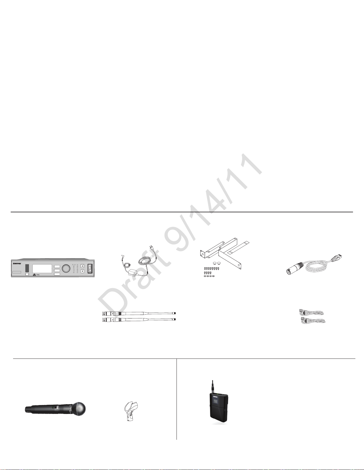
Furnished Accessories
All Systems
gain poweraudio
control
RF
A B
ULXD4
Digital Wireless Receiver
sync
ULXD4S Receiver PS41 Power Supply
ENTER
EXIT
SCAN
AA Alkaline
batteries (2)
Handheld Systems Bodypack System
ULXD2 Handheld
Transmitter
OL
push
Microphone
OL
Rackmount Kit (1) 5’ Ethernet
1/2 Wave Antenna (2) 2’ BNC Cable (2)BNC Bulkead Adapters (2)
Microphone Clip ULXD1 Bodypack Transmitter
Cartridge
Cable (1)
• One of the following:WA302
instrument cable
• Beta 98H/C instrument
microphone
• Lavalier microphone (MX150,
MX153, WL183, WL184, WL185)
• WH30 headworn microphone
4
Page 4
Receiver
Draft 9/14/11
6
7
8
ULXD4
Digital Wireless Receiver
1
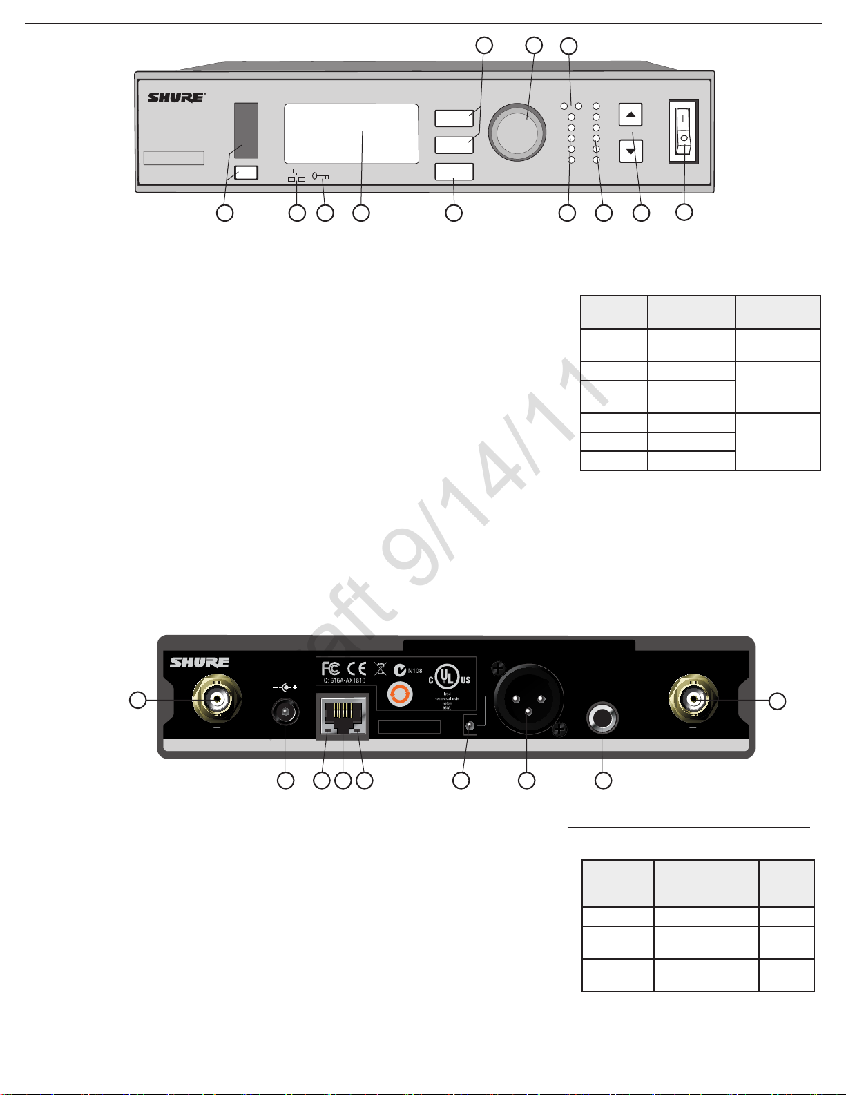
Front Panel
① Sync Button
Press the sync button while the receiver and
transmitter IR windows are aligned to transfer
settings from the receiver to the transmitter
② Infrared (IR) Sync Window
Sends IR signal to the transmitter for sync
③ Network Icon
Illuminates when the receiver is connected with
other Shure devices on the network. IP Address
must be valid to enable networked control
④ Encryption Icon
Illuminates when AES-256 encryption is
activated:
⑤ LCD Display
Displays settings and parameters
⑥ Scan Button
Press to find the best channel or group
⑦ Menu Navigation Buttons
Use to select and navigate through parameter
menus
Utilities > Encryption
sync
control
ENTER
EXIT
SCAN
3
2
⑧ Control Wheel
Push to select menu items for editing, turn to
edit a parameter value
⑨ RF Diversity LEDs
Indicate antenna status:
•Blue = normal RF signal between the receiver
and transmitter
•Red = interference detected
•Off = No RF connection between the receiver
and transmitter
Note: the receiver will not output audio unless
one blue LED is illuminated
⑩ RF Signal Strength LEDs
Indicate the RF signal strength from the
transmitter:
•Amber = Normal (-90 to -70 dBm)
•Red = Overload (greater than -25 dBm, see
Troubleshooting)
5
push
RF
A B
OL
9
⑪ Audio LEDs
⑫ Gain Buttons
⑬ Power Switch
gain poweraudio
OL
10
11
Indicate average and peak audio levels:
LED
Red (6) -0.1 dBFS
Yellow (5) -6 dBFS
Yellow/
Green (4)
Green (3) -20 dBFS
Green (1) -40 dBFS
Adjust channel gain
Powers the unit on or off
12
Audio Signal
Level
-12 dBFS
Description
Overload/
limiter
Normal peaks
Signal PresentGreen (2) -30 dBFS
1
12V OUT
150 mA
Back Panel
① RF Antenna Diversity Input Jack (2)
For antenna A and antenna B.
② Power Supply Jack
Connect the supplied 15 V DC external power
supply
③ Network Speed LED (Amber)
•Off = 10 Mbps
•On = 100 Mbps
④ Ethernet Port
Connect to an Ethernet network to enable
remote control and monitoring
ULXD2ULXD2
15V 0.6A
25
L5 644-800 MHz
344
2
⑤ Network Status LED (Green)
•Off = no network link
•On = network link active
•Flashing = network link active, flash rate
corresponds to traffic volume
⑥ Mic/Line Switch
Applies a 30 dB pad in
only)
⑦ Balanced XLR Audio Output
Connect to a mic or line level input
⑨ Balanced 1/4” (6.35 mm) TRS Audio Output
Connect to a mic or line level input
5
line
mic
6
mic position (XLR output
www.shure.com
12V OUT
mic / linemic / linepowerpowerantenna . Bantenna . B antenna . Aantenna . A
7
inst / auxinst / aux
8
150 mA
Receiver Output Gain
Output
Jack
1/4” TRS 0 dB (unity) +12 dBV
XLR (line
setting)
XLR (mic
setting)
Output Level
(system gain = 0)
+6 dB +18 dBV
-24 dB -12 dBV
1
Full
Scale
Output
6
Page 5
Transmitters
Draft 9/14/11
①
②
③
⑨
④
⑤
⑥
⑦
⑧
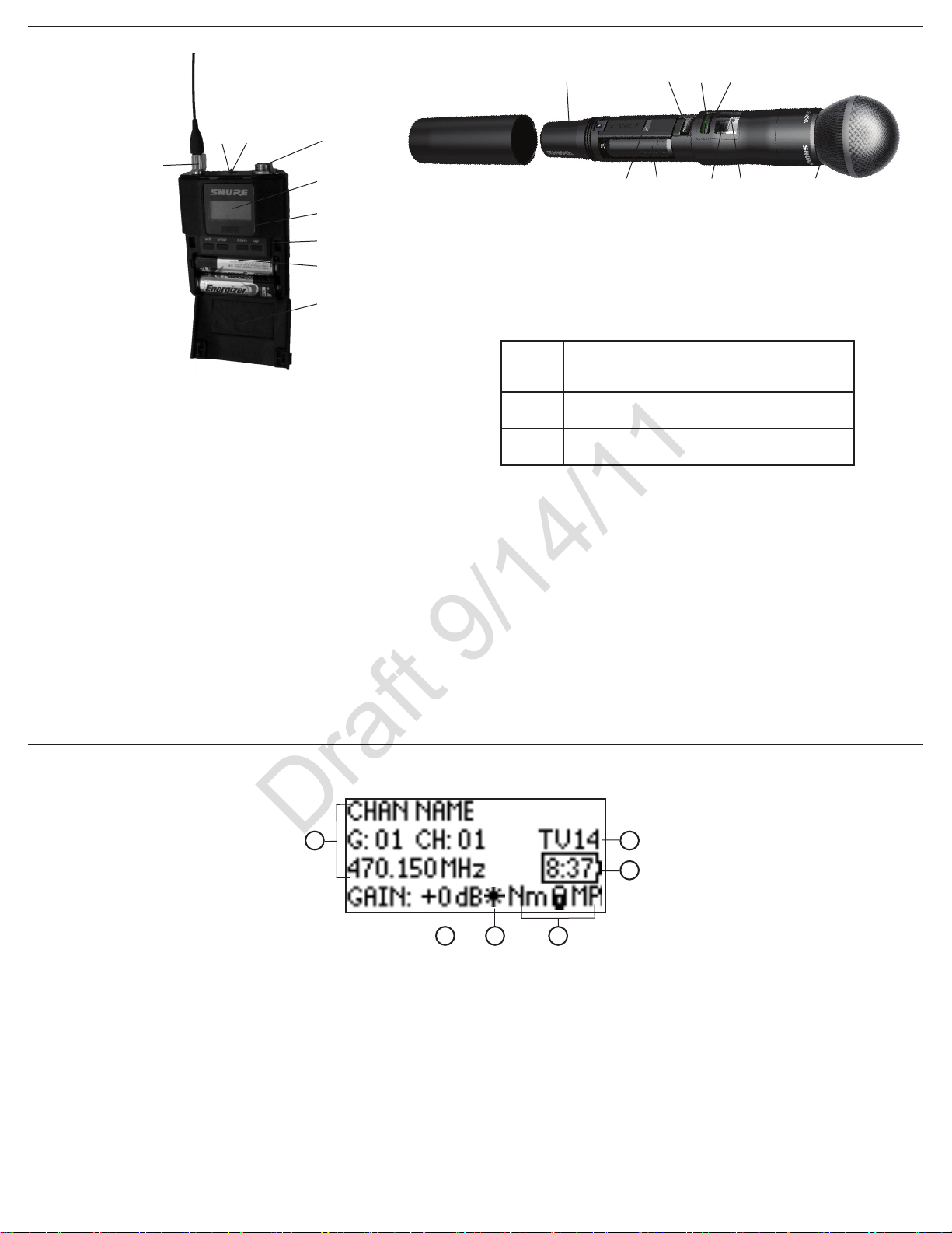
① Power LED
•Green = unit is powered on
•Red = low battery or battery error (see Troubleshooting)
•Amber = power switch is disabled
② On/Off Switch
Powers the unit on or off
③ TA4M Input Jack
Connects to a 4-Pin Mini Connector (TA4F) microphone or instrument cable
④ LCD Display:
View menu screens and settings. Press any control button to activate the
backlight
⑤ Infrared (IR) Port
Align with the receiver IR port during an IR Sync for automated transmitter
programming
⑩
⑧
ULXD2 4-Way Menu Navigation Button
⑥ Menu Navigation Buttons
Use to navigate through parameter menus and change values.
exit
enter
▼▲
⑦ Battery Compartment
Requires Shure SB900 rechargeable battery or 2 AA batteries.
⑧ AA Battery Adapter
Handheld: rotate and store in the battery compartment to use a Shure rechargeable battery pack
Bodypack: remove to accommodate a Shure rechargeable battery pack
⑨ Detachable Bodypack Antenna
For RF signal transmission
⑩ Integrated Antenna
For RF signal transmission
⑪ Microphone Cartridge
See Optional Accessories for a list of compatible cartridges
Acts as a ‘back’ button to return to previous
menus or parameters without confirming a value
change
Enters menu screens and confirms parameter
changes
Use to scroll through menu screens and to change
parameter values
⑥
⑦
①
⑤
②
④
⑪
Home Screen
Receiver
1
2
① Receiver Information
Use UTILITIES > HOME INFO to rearrange the
following information:
•Channel name
•Group
•Channel
•Frequency
② Gain Setting
0 to +60 dB, or Mute
③ Mic. Offset Indicator
Indicates the transmitter is set to a gain offset
value
④ Transmitter Settings
The following information cycles when a
transmitter is tuned to the receiver’s frequency:
•Transmitter Type (ULXD1=Bodypack;
ULXD2=Handheld)
•Input Pad (Bodypack only)
•RF Power Level (Lo=1 mW; Nm=10 mW; Hi=20
mW)
•Transmitter Lock Status (M=Menu; P=Power)
Note: -No TX- is displayed when there is no RF
connection between a receiver and transmitter
6
5
3 4
⑤ Battery Runtime Indicator
Shure SB900 battery: runtime is displayed in
minutes remaining
AA Batteries: runtime is displayed with a 5-bar
indicator
⑥ TV Channel
Displays the TV channel that contains the tuned
frequency
7
Page 6

Transmitter
Draft 9/14/11
1
8
7
6
3 4
① Transmitter Information
Scroll▲▼atthehomescreentorearrangethe
following information:
•Channel name
•Group
•Channel
•Frequency
2
② Power Lock Indicator
Indicates power switch is disabled
③ Battery Runtime
See Batteries for more details
④ Menu Lock Indicator
Indicates menu navigation buttons are disabled
⑤ Mic. Offset
Displays microphone offset gain value
Batteries
The transmitter runs on two AA batteries or the Shure SB900 rechargeable battery.
5
⑥ RF Power
Displays RF power setting
⑦ Bodypack Input Pad
The input signal is attenuated 12 dB
⑧ Encryption Icon
Indicates encryption is enabled on the receiver
and has been transferred to the transmitter from
a sync
PGXD
Drawings Needed:
1. Polarity
2. AA Clip storage
AA Batteries
A 5-segment icon on the receiver and transmitter menu screens indicates battery charge.
For accurate battery runtime monitoring, set the transmitter to the appropriate
battery type:
AA Battery Runtime Chart
Battery
Indicator
Total Battery
Runtime
UTILITY > BATTERY > SET TYPE.
LED
Color
Green
Green
Green
Green
Red
Red
RF Power Setting
1/10 mW 20 mW
## ##
Shure SB900 Rechargeable Battery
When using an SB900 rechargeable battery, the receiver and
transmitter home screens display the number of hours and minutes
remaining.
Detailed information for the SB900 is displayed in the receiver
menu and the transmitter menu:
HEALTH: Overall battery health
CHARGE: Percentage of a full charge
CYCLES: Number of times the battery has been charged
TEMP: Battery temperature in Celsius and Fahrenheit
Note: Reference the SB900 Battery and SBC800 Charger user guides for
additional rechargeable battery information.
UTILITY > BATTERY > BATT. STATS
BATTERY INFO
8
Page 7

powercontrol
Setting Gain
RF
AB
L
OL
gain poweraudio
RF
A B
OL
gain poweraudio
OL
Draft 9/14/11
Adjust gain at the receiver so that the average signal levels are solid green
and yellow with peaks that flicker the red overload LED. Attenuate the gain if
the signal overloads repeatedly.
Set the XLR output to line-level when possible to optimize noise performance.
Receiver Gain Controls
The receiver adjusts the system audio gain from 0 to +60 dB. No transmitter
gain is necessary to optimize the gain structure. This allows you to make adjustments during a live performance.
Adjust Gain at the Receiver
audio gain
Reading the Audio Meter
OL
Audio peaks illuminate the LEDs for 2 seconds while RMS
signal is displayed in realtime.
OL (Overload) LED: Illuminates red when the internal limiter
is engaged, preventing digital clipping.
Mute
To mute the audio, use Wireless Workbench or a third-party control device.
Transmitter Input Clip
The following warning displays on the receiver LCD panel when the transmitter
input is clipped:
ULXD4
Digital Wireless Receiver
control
ENTER
sync
EXIT
SCAN
push
gain poweraudio
RF
A B
OL
OL
Pressthe▲▼gain buttons on the front of
the receiver to adjust in 1 dB increments.
Large Gain Adjustments
control
ENTER
EXIT
SCAN
AUDIO menu
push
Press and hold a
gain button
or
Use the control wheel in
the
Mic. Offset
Use this to compensate for signal level differences between transmitters that
share the same receiver.
Set the offset gain on a low signal level transmitter to match a louder transmitter:
Utility > Mic.Offset
To correct, attenuate the signal source. If the source cannot be attenuated
while using a bodypack transmitter, select
INPUT PAD from the main menu to
attenuate the input signal 12 dB.
Note: For normal gain adjustments, use the receiver gain buttons.
9
Page 8

RF
Draft 9/14/11
RF Power
Reference the following table for setting RF Power:
RF Power
Setting
1 mW
10 mW
20 mW
Note: Using the 20 mW setting decreases the transmitter battery runtime
and reduces the number of compatible systems. See the specifications
section for details.
Range Application
≤100ft.
≤300ft. Typical setups
≤420ft.
For increased channel reuse at close
distances
For hostile RF environments or longdistance applications
Scan and Sync
Use this procedure to tune a receiver and transmitter to the best open channel.
Important! Before you begin:
Turn off all transmitters for the systems you are setting up. (This prevents
them from interfering with the frequency scan.)
Turn on potential sources of interference such as other wireless systems or
devices, computers, CD players, large LED panels, effects processors, and
digital rack equipment so they are operating as they would be during the presentation or performance (so the scan will detect and avoid any interference
they generate).
Interference Detection
Interference Detection analyzes the quality of the RF signal and detects
interference conditions that have caused an audio signal dropout. When interference is identified, the RF LEDS illuminate red and the following warning
displays on the receiver LCD panel.
Perform a Scan and Sync during a performance break if the warning display
persists or the audio drops out repeatedly.
1
3 4
2
1. Perform a channel scan on the receiver: SCAN > CHANNEL SCAN.
2. Select a group and press the SCAN button. SCANNING displays on the LCD
while it searches for an open frequency.
3. After the scan completes, the receiver displays the group, channel and
frequency of the best available channel. Press the flashing ENTER button to
save the value to the receiver.
4. Power on the ULXD transmitter.
5. Press the sync button on the receiver.
6. Align the IR windows until the receiver IR port illuminates red.
7. When complete, SYNC SUCCESS! appears. The transmitter and receiver are
now tuned to the same frequency.
Multiple System Setup
A setup using networked receivers is the fastest and easiest way to distribute
the best open channel to each system. See Networking Receivers for networking details.
Networked Receivers
1. Turn on all receivers.
2. Conduct a group scan on the first receiver to find the best group of frequencies in your RF environment: SCAN > GROUP SCAN.
3. Press ENTER to accept the group number and automatically assign the next
best channel to each receiver on the network.
4. Turn on a transmitter and sync to the receiver. Repeat this step for each
additional system.
5
6
Non-networked Receivers
1. Turn on all receivers.
2. Conduct a group scan on the first receiver to find the best group of frequencies in your RF environment:
3. Select a group that contains enough open frequencies to accommodate the
entire setup.
4. Turn on the transmitter and sync to the first receiver.
Repeat the following steps for each additional system:
5. Go to SCAN > CHANNEL SCAN on the receiver to select the group assigned
in step 2
6. Press the SCAN button to find the next best open frequency.
7. Press ENTER to assign the channel to the receiver.
8. Sync the transmitter to the receiver.
SCAN > GROUP SCAN
10
Page 9

Manual Frequency Selection
Draft 9/14/11
To manually adjust group, channel or frequency, use the RADIO > SET FREQ
menu.
Networking Receivers
Device ID
Name the receiver’s Device ID to easily identify it through the network or in
Wireless Workbench:
UTILITIES > NETWORKING > Dev. ID
The receiver uses an Ethernet connection to network with other components.
For automatic network configuration, use a DHCP enabled Ethernet switch
such as the Shure AXT620. Use multiple Ethernet switches to extend the network for larger installations.
Note: Note use only one DHCP server per network.
Automatic IP Addressing
1. If using a Shure AXT620 Ethernet switch, set the DHCP switch to ON.
2. Set the IP Mode to Automatic for all receivers: UTILITIES > NETWORKING >
CTRL NETWORK
Manual IP Addressing
1. Connect the receivers to an Ethernet switch.
2. Set the IP Mode to Manual for all devices (UTILITIES > NETWORKING >
MODE)
3. Set compatible IP addresses for all devices.
4. Set the subnet mask to the same value for all devices.
Troubleshooting
• Use only one DHCP server per network
• All devices must share the same subnet mask
• All receivers must have the same level of firmware revision installed
• Look for the illuminated network icon on the front panel of each device:
If the icon is not illuminated, check the cable connection and the LEDs on
the network jack.
If the LEDs are not on and the cable is plugged in, replace the cable and
recheck the LEDs and network icon.
To check connectivity of WWB6 to the network:
1. Start WWB6 software and use Inventory view to see devices connected to
the network.
2. If not, find the IP address from one of the devices on the network (such as
an ULXD receiver) and see if you can ping it from the computer running
WWB6.
3. From a WINDOWS/MAC command prompt, type ‘ping IPADDRESS’ of the
device (e.g. “ping 192.168.1.100”).
4. If the ping returns success (no packet loss), then the computer can see the
device on the network. If the ping returns failure (100% packet loss), then
check the IP address of the computer to ensure it’s on the same subnet as
the Axient device.
5. If the pings are successful and the devices still do not show up in the WWB6
inventory, check to ensure all firewalls are either disabled or allow the WWB
network traffic to pass to the application. Check that firewall settings are not
blocking network access.
ULXD4
Digital Wireless Receiver
ULXD4
Digital Wireless Receiver
ULXD4
Digital Wireless Receiver
ON
gain poweraudio
control
RF
A B
OL
OL
ENTER
sync
sync
sync
EXIT
SCAN
push
gain poweraudio
control
RF
A B
OL
OL
ENTER
EXIT
SCAN
push
gain poweraudio
control
RF
A B
OL
OL
ENTER
EXIT
SCAN
push
Addressing with Shure
OFF
DH CP
Automatic IP
AXT620
11
Page 10

Home Screen Display Options
Draft 9/14/11
Receiver
Edit the following parameters in the UTILITIES menu:
EDIT NAME: Edits the receiver’s channel name (transfers to the transmitter
during a sync).
HOME INFO: Changes the information displayed on the LCD home screen:
DISPLAY: Use BRIGHTNESS parameter to adjust the brightness of the LCD
panel, meter LEDs and front panel icons and CONTRAST parameter to adjust
the contrast of the LCD panel.
Transmitter
Home Screen: Pressthe▲▼arrowsatthehomemenutodisplayoneofthe
following screens:
Locking Controls and Settings
Use the LOCK feature to prevent accidental or unauthorized changes to the hardware. Attempting to access a
locked feature will display the following message:
Receiver
UTILITIES > LOCK
MENU: All menu paths are inaccessible. To unlock, press the EXIT button, turn
the control wheel to select UNLOCKED and press ENTER to save.
GAIN: Gain adjustment is locked
POWER: Power switch is disabled
SCN/SYC: Cannot perform a Scan and Sync
Encryption
ULXD features Advanced Encryption Standard (AES-256) encryption, conforming to the US Government National Institute of Standards and Technology
(NIST) publication FIPS-197.
1. Enable encryption on the receiver: UTILITIES > ENCRYPTION. The encryption
symbol illuminates green and the LCD displays SYNC NOW FOR ENCYPTION.
2. Sync the transmitter to the receiver. The encryption symbol displays on the
transmitter.
Note: Any change to the encryption status on the receiver requires an
sync to transfer the setting to the transmitter. The Encryption Mismatch
warning will display on the receiver LCD panel if they are not on the same
setting.
System Reset
Use this feature to overwrite current settings with saved or factory default
settings.
Save a System Preset
To save the current receiver setup as a new preset: UTILITES >
SYSTEM RESET > SAVE > CREATE NEW PRESET.
Restore Settings
To restore saved or factory default settings:
1. Go to UTILITES > SYSTEM RESET > RESTORE.
2. Scroll to the preset or default settings option and press ENTER. The following warning will display:
3. Press the flashing ENTER button to overwrite the current settings.
Transmitter
UTILITY > LOCK
MENU: All menu paths are inaccessible. To unlock, press the ENTER 4 times:
UTILITY > LOCK > UNLOCKED
POWER
: Power switch is disabled
Quick-Lock Option: To turn on the transmitter with its power and menu navi-
gationbuttonslocked,pressandholdthe▼buttonduringpower-onuntilthe
locked message is displayed.
Tounlock,turnthepowerswitchtotheoffposition,thenpressandholdthe▼
button while turning the power switch to the on position.
Transmitter Presets
Use the TX SYNC SETUP menu to store settings on the receiver to transfer to
the transmitter during a sync. Each parameter has the default value KEEP,
which leaves that setting unaffected by a sync.
Feature Setting
BP PAD 0 dB, -12 dB
LOCK All, Power, Menu, None
RF POWER High, Mid, Low
BP OFFSET,
HH OFFSET
BATT NiMH, Lithium, Alkaline
Cust. Group On, Off
Note: When Cust. Groups is set to on, it may take up to 30 seconds to complete an IR sync.
0 dB to +21 dB (in 3 dB increments)
Advanced RF
RF Mute
Use this to turn on a transmitter without interfering
with the RF spectrum.
Press and hold the
til RF MUTED is displayed. To un-mute, restart the
transmitter.
Custom Groups
Use this feature to create up to six groups of manually selected frequencies
that can be exported to networked receivers to simplify system setup.
To create a custom group:
Note: Use Wireless Workbench or Wireless Frequency Finder to select the
best compatible frequencies. See www.shure.com for more information.
To export a custom group:
1. Go to UTILITES > ADVANCED RF > CUSTOM GROUPS > EXPORT. The follow-
ing screen will display.
2. Press the flashing ENTER button to export all custom groups to all receivers
on the network.
Antenna Bias
To turn off: UTILITES > ADVANCED RF > ANTENNA BIAS.
exit button during power-on un-
UTILITES > ADVANCED RF > CUSTOM GROUPS
12
Page 11

Connecting to an AMX or Crestron System
Draft 9/14/11
The following messages can be used to communicate with an AMX or Crestron unit across an Ethernet connection.
Message Types
The control system sends the following command messages:
SET
GET
REPORT
Syntax
All messages sent and received are ASCII characters.
1. Each message begins with a "<" followed by a space.
2. Each message ends with a space followed by an ">"
3. Each message is terminated by a carriage return and line feed (CRLF).
The control system may need to enter the hex value, equivalent to 0x0D0A.
Please see the control system user guide for information on entering carriage returns.
4. If the message is a box parameter, there should be no channel number in
the string.
Command Response Table
Action COMMAND RESPONSE
View Transmitter Name GET DEVICE_NAME REPORT DEVICE_NAME vvvvvvvv
Set Channel Name SET x CHAN NAME vvvvvvvv REPORT x CHAN_NAME vvvvvvvv
Get Channel Name GET x CHAN NAME REPORT CHAN_NAME vvvvvvvv
Set Audio Level SET x AUDIO_IN_LVL vvvv REPORT x AUDIO_IN_LVL vvvv
View Audio Level GET x AUDIO_IN_LVL REPORT x AUDIO_IN_LVL vvvv
Set Transmitter Group & Channel SET x GROUP_CHAN gg,cc
View Transmitter Group & Channel GET x GROUP_CHAN REPORT x GROUP_CHAN gg,cc
Set Transmitter Frequency SET x FREQUENCY vvvvvvvvvvv
View Transmitter Frequency GET x FREQUENCY REPORT x FREQUENCY vvvvvvvvvvv
Set RF Tx Level SET x RF_TX_LVL vvvvvv REPORT x RF_TX_LVL vvvvvv
View RF Tx Level GET x RF_TX_LVL REPORT x RF_TX_LVL vvvvvv
Set RF Mute
View RF Mute
Set Audio Tx Mode
View Audio Tx Mode GET x AUDIO_TX_MODE
Set Audio Input Line Level
View Audio Input Line Level GET x AUDIO_IN_LINE_LVL
Set Metering Rate
View Metering Rate GET x METER_RATE
Audio Meter Level REPORT x AUDIO_IN_LVL_L vvvvvvvvvvv
Sent from the control system to the Shure device to change the value of a parameter. Used to set the parameter to a specific value. Once a
SET command is sent, the Shure device sends back a REPORT string with the current resultant setting.
Gets the current value of a parameter. Once a GET command is sent, the Shure device will send back a REPORT string with the current setting.
Reports the current value for a parameter. The REPORT string is sent from the Shure device to the Control system in response to a SET or GET
command. The REPORT string is also sent when the value of the parameter is changed on the Shure device.
Example Messages
<GET 1 FREQUENCY >/0d/0a
Example Messages for Channel Parameters
• <REPORT 1 FREQUENCY 578000 >/0d/0a
Example Messages for Box Parameters
• <SET DEVICE_NAME Shure >/0d/0a
• <REPORT DEVICE_NAME Shure >/0d/0a
SET x RF_MUTE vvvv
1 = mute, 0 = unmute
GET x RF_MUTE
1 = mute, 0 = unmute
SET x AUDIO_TX_MODE vvvv
1 = mono, 2 = point to point, 3 = stereo
SET x AUDIO_IN_LINE_LVL vvvv
0 = off (Aux), 1 = on (Line)
SET x METER_RATE vvvvvvvvvvv
0 = off, value in milliseconds
1
REPORT x FREQUENCY vvvvvvvvvvv REPORT
x GROUP_CHAN gg,ccvvv
REPORT x FREQUENCY vvvvvvvvvvv
REPORT x GROUP_CHAN --,--vvv
REPORT x RF_MUTE vvvv
1 = mute, 0 = unmute
REPORT x RF_MUTE vvvv
1 = mute, 0 = unmute
REPORT x AUDIO_TX_MODE vvvv
1 = mono, 2 = point to point, 3 = stereo
REPORT x AUDIO_TX_MODE vvvv
1 = mono, 2 = point to point, 3 = stereo
REPORT x AUDIO_IN_LINE_LVL vvvv
0 = off (Aux), 1 = on (Line)
REPORT x AUDIO_IN_LINE_LVL vvvv
0 = off (Aux), 1 = on (Line)
REPORT x METER_RATE vvvvvvvvvvv
0 = off, value in milliseconds
REPORT x METER_RATE vvvvvvvvvvv
0 = off, value in milliseconds
REPORT x AUDIO_IN_LVL_L vvvvvvvvvvv
REPORT x AUDIO_IN_LVL_R vvvvvvvvvvv
2
3
13
Page 12

Firmware
Draft 9/14/11
Firmware is embedded software in each component that controls functionality. Periodically, new versions of firmware are developed to incorporate additional
features and enhancements. To take advantage of design improvements, new versions of the firmware can be uploaded and installed using the Firmware Update
Manager tool available in Shure’s Wireless Workbench
Perform the following steps to update the firmware for the ULXD system:
1. Download the latest firmware to WWB software: Tools > Firmware Update Manager. Click Check Now to view and download the latest versions.
2. Connect the receiver and computer to the same network.
3. Download the latest firmware to the receiver.
4. To transfer firmware to the transmitter, go to UTILITIES > TX FW UPDATE on the receiver.
5. Align the transmitter and receiver IR ports.
6. Press ENTER on the receiver to begin the download to the transmitter. IR ports must be aligned for the entire download, which can take 50 seconds or longer.
Once the download is complete, the receiver automatically begins the firmware update, which overwrites the existing firmware.
CAUTION! Do not turn off the receiver until the update is complete.
®
(WWB) software. Software is available for download from http://www.shure.com/wwb.
Troubleshooting
Issue See Solution...
No Sound Power, Cables, or RF
Faint sound or distortion Gain
Lack of range, unwanted noise bursts, or dropouts RF
Cannot turn transmitter off or change frequency settings, or can’t program receiver Interface locks
Encryption error message Encryption Mismatch
Power
Make sure that the receiver and transmitter are receiving sufficient voltage.
Use the 15 V DC power supply furnished with the ULXD4 receiver. Check the
battery indicators and replace the transmitter batteries if necessary.
Gain
Adjust the system gain on the front of the receiver. Ensure the output level
(XLR output only) on the back of the receiver corresponds to the input of the
mixing console, amplifier, or DSP.
Cables
Check that all cables and connectors are working correctly.
Interface Locks
The transmitter and the receiver can be locked to prevent accidental or unauthorized changes. A locked feature or button will produce the Locked screen on
the LCD panel.
Encryption Mismatch
Re-sync the receiver and transmitter after enabling or disabling encryption.
Radio Frequency (RF)
RF LEDs
If neither blue RF Diversity LED is illuminated, then the receiver is not detecting the presence of a transmitter.
The amber
received. This signal could be from the transmitter, or it could be from an
interfering source, such as a television broadcast. If more than one or two
of the amber RF LEDs are still illuminated while the transmitter is off, then that
channel has too much interference, and you should try a different channel.
The red
unless you are using more than one system at the same time, in which case, it
can cause interference in the other system.
RF Signal Strength LEDs indicate the amount of signal being
RF LED indicates RF overload. This will usually not cause a problem
Compatibility
• Perform a Scan and Sync to ensure the transmitter and receiver are set to
the same group and channel.
• Look at the label on the transmitter and receiver to make sure they are in
the same band (G50, J50, L50, etc...).
Reducing Interference
• Perform a group or channel scan to find the best open frequency. Perform a
sync to transfer the setting to the transmitter.
• For multiple systems, check that all systems are set to channels in the same
group (systems in different bands do not need to be set to the same group).
• Maintain a line of sight between transmitter and receiver antennas.
• Move receiver antennas away from metal objects or other sources of
RF interference (such as CD players, computers, digital effects, network
switches, network cables and Personal Stereo Monitor (PSM) wireless
systems).
• Eliminate RF overload (see below).
Increasing Range
If the transmitter is more than 6 to 60 m (20 to 200 ft) from the receiver antenna, you may be able to increase range by doing one of the following:
• Reduce interference (see above).
• Increase transmitter RF power level.
• Use an active directional antenna, antenna distribution system, or other
antenna accessory to increase RF range.
Eliminating RF Overload
If you see the red RF LED on a receiver, try the following:
• Reduce the transmitter RF power level
• Move the transmitter further away from the receiver—at least 6 m (20 ft)
• If you are using active antennas, reduce antenna or amplifier gain.
• Use omnidirectional antennas
14
Page 13

Tables and Diagrams
Draft 9/14/11
Frequency Range and Transmitter Output Power
Band Frequency Range
( MHz)
G50 470 to 534 1/10/20
G51 470 to 534 1/10/20
G52 479 to 534 1/10
H51 534 to 598 1/10/20
H52 534 to 565 1/10
J50 572 to 636 10/50
K51 606 to 670 1/10
L50 632 to 696 1/10/20
ULXD1 TA4M Connector
Power ( mW)
500 Ω 500 Ω
100 µF
1µF
Z
Active
Load
1M Ω
470 pF
Pad
12dB
Band Frequency Range
L51 632 to 696 1/10/20
P51 710 to 782 1/10/20
R51 800 to 810 1/10/20
JB (Tx only) 806 to 810 1/10
AB (Rx and Tx) 770 to 810
Q51 794 to 806 10/50
X50 925 to 932 10
5 V DC
Audio
Input
Ground
( MHz)
Ground
Bias Voltage
Audio Input
Active Load
Power ( mW)
“A” Freq (770.250-
805.750) : 20mW /
10mW / 1mW
“B” Freq: (806.125-
809.750) = 10mW /
1mW
ULXD4 Audio Outputs
22 µF
instrument/ aux
22 µF
50 Ω
50 Ω
50 Ω
22 µF
22 µF
-30 dB
mic/ line
17
Page 14

Certifications
Draft 9/14/11
ULXD1, ULXD2, ULXD4
Meets essential requirements of the following European Directives:
• Low Voltage Directive 2006/95/EC
• R&TTE Directive 99/5/EC
• WEEE Directive 2002/96/EC, as amended by 2008/34/EC
• RoHS Directive 2002/95/EC, as amended by 2008/35/EC
Note: Please follow your regional recycling scheme for electronic waste
• Conforms to European Regulation (EC) No. 1275/2008, as amended.
Meets requirements of the following standards: EN 300 422 Parts 1 and 2, EN 301 489 Parts 1 and 9.
ULXD1, ULXD2
Certified under FCC Part 74.
Certified by IC in Canada under RSS-123 and RSS-102.
IC: 616A-ULXD1 G50, 616A-ULXD1 J50, 616A-ULXD1 L50; 16A-ULXD2 G50, 616A-ULXD2 J50, 616A-ULXD2 L50.
FCC: DD4ULXD1G50, DD4ULXD1J50, DD4ULXD1L50; 16A-ULXD2G50, DD4ULXD2J50, DD4ULXD2L50.
ULXD4
Approved under the Declaration of Conformity (DoC) provision of FCC Part 15.
Certified in Canada by IC to RSS-123.
IC: 616A-ULXD4 G50, 616A-ULXD4 J50, 616A-ULXD4 L50
This Class B digital apparatus complies with Canadian ICES-003. Cet appareil numérique de la classe B est conforme à la norme NMB-003 du Canada.
This device complies with Industry Canada licence-exempt RSS standard(s). Operation of this device is subject to the following two conditions: (1) this device may
not cause interference, and (2) this device must accept any interference, including interference that may cause undesired operation of the device.
Le présent appareil est conforme aux CNR d’Industrie Canada applicables aux appareils radio exempts de licence. L’exploitation est autorisée aux deux conditions
suivantes : (1) l’appareil ne doit pas produire de brouillage, et (2) l’utilisateur de l’appareil doit accepter tout brouillage radioélectrique subi, même si le brouillage
est susceptible d’en compromettre le fonctionnement.
Note: EMC conformance testing is based on the use of supplied and recommended cable types. The use of other cable types may degrade EMC
performance.
Changes or modifications not expressly approved by the manufacturer could void the user’s authority to operate the equipment.
The CE Declaration of Conformity can be obtained from Shure Incorporated or any of its European representatives. For contact information please visit www.
shure.com
The CE Declaration of Conformity can be obtained from: www.shure.com/europe/compliance
Authorized European representative:
Shure Europe GmbH
Headquarters Europe, Middle East & Africa
Department: EMEA Approval
Jakob-Dieffenbacher-Str. 12
75031 Eppingen, Germany
Phone: 49-7262-92 49 0
Fax: 49-7262-92 49 11 4
Email: info@shure.de
Information to the user
This equipment has been tested and found to comply with the limits for a Class B digital device, pursuant to Part 15 of the FCC Rules. These limits are designed to
provide reasonable protection against harmful interference in a residential installation. This equipment generates uses and can radiate radio frequency energy and,
if not installed and used in accordance with the instructions, may cause harmful interference to radio communications. However, there is no guarantee that interference will not occur in a particular installation. If this equipment does cause harmful interference to radio or television reception, which can be determined by turning
the equipment off and on, the user is encouraged to try to correct the interference by one or more of the following measures:
• Reorient or relocate the receiving antenna.
• Increase the separation between the equipment and the receiver.
• Connect the equipment to an outlet on a circuit different from that to which the receiver is connected.
• Consult the dealer or an experienced radio/TV technician for help.
LICENSING INFORMATION
Licensing: A ministerial license to operate this equipment may be required in certain areas. Consult your national authority for possible requirements. Changes or
modifications not expressly approved by Shure Incorporated could void your authority to operate the equipment. Licensing of Shure wireless microphone equipment is the user’s responsibility, and licensability depends on the user’s classification and application, and on the selected frequency. Shure strongly urges the
user to contact the appropriate telecommunications authority concerning proper licensing, and before choosing and ordering frequencies.
18
 Loading...