


ULXD2H50
ULX-D
ULXD4D Dual Receiver
ULXD4Q Quad Receiver
©2012 Shure Incorporated
27A20228 (Rev. 1)
ULX-D Digital Wireless Microphone System


General Description
Shure ULX-D™ Digital Wireless offers uncompromising 24-bit audio quality and RF performance, with intelligent, encryption-enabled hardware, flexible
receiver options, and advanced rechargeability options for professional sound reinforcement.
A breakthrough in wireless audio quality, Shure digital processing enables ULX-D to deliver the purest reproduction of source material ever available in a
wireless system, with a wide selection of trusted Shure microphones to choose from. Extended 20 Hz – 20 kHz frequency range and flat response captures
every detail with clarity, presence, and incredibly accurate low end and transient response. With greater than 120 dB, ULX-D delivers wide dynamic range for
excellent signal-to-noise performance. Optimized for any input source, ULX-D eliminates the need for transmitter gain adjustments.
ULX-D sets a new and unprecedented standard for spectral efficiency and signal stability. The intermodulation performance of ULX-D is an incredible
advancement in wireless performance, enabling a dramatic increase in the number of simultaneous active transmitters on one TV channel. Rock-solid RF
signal with zero audio artifacts extends over the entire range. For applications where secure wireless transmission is required, ULX-D offers Advanced
Encryption Standard (AES) 256-bit encrypted signal for unbreakable privacy.
For scalability and modular flexibility, ULX-D receivers come in single, dual, and even quad channel versions. The dual and quad channel receivers offer
conveniences such as RF cascade, internal power supply, bodypack frequency diversity, audio output channel summing, and Dante™ digital networking
for multi-channel audio over Ethernet. All receivers offer High-Density mode for applications where high channel counts are needed, greatly increasing the
amount of simultaneous channels possible over one frequency band.
Advanced Lithium-ion rechargeability provides extended transmitter battery life over alkaline batteries, battery life metering in hours and minutes accurate to
within 15 minutes, and detailed tracking of battery health status.
Generations ahead of any other available system in its class, ULX-D brings a new level of performance to professional sound reinforcement.
Features
Uncompromising Digital Wireless Audio
• 24-bit/48 kHz digital audio that delivers incredibly clear and accurate
reproduction of the source material
• 20 Hz – 20 kHz frequency range with flat response
• Greater than 120 dB dynamic range through the analog outputs
• Built-in limiter circuitry prevents digital audio clipping from excessive signal
levels.
• 130 dB dynamic range (typical) using Dante™ digital networked audio
• 60 dB of adjustable system gain easily accessible from the receiver front
panel
• No transmitter gain adjustments needed - optimized for any input source
• Wide selection of trusted Shure Microphones
Extremely Efficient and Reliable RF Performance
• Up to 72 MHz overall tuning range (region dependent)
• Up to 17 active transmitters in one 6 MHz TV channel (22 on an 8 MHz TV
channel)
• High Density mode enables up to 47 active transmitters in one 6 MHz TV
channel (63 in one 8 MHz TV channel), with no audio quality degradation
• Rock-solid signal stability with no audio artifacts over the entire 100 meter
line-of-sight range using standard supplied ½ wave antennas
• Selectable 1, 10, and 20 mW transmitter RF output power
• Optimized scanning automatically finds, prioritizes, and selects the
cleanest frequencies available
Scalable, Intelligent Hardware
• Single (half-rack), Dual and Quad (full-rack) receiver form factors for any
size installation
• AES 256-bit encryption on all channels
• Ethernet networking for streamlined setup across multiple receivers
• Wireless Workbench® 6 software compatible for advanced frequency
coordination, monitoring, and control
• AMX/Crestron control
• AXT600 Axient™ Spectrum Manager compatibility
• Rugged metal housing on both transmitters and receiver
• Dual and Quad receivers additionally feature:
• RF cascade ports, internal power supply, and dual Ethernet ports
• Dante™ digital networked audio over Ethernet
• Bodypack Frequency Diversity ensures uninterrupted audio for mission-critical
applications
• Audio summing routes audio signal to multiple outputs
Shure Advanced Power Management
• Adapted from industry-leading Axient™ rechargeable technology
• Lithium-Ion chemistry and intelligent Shure battery circuitry results in
rechargeable batteries with zero memory effect and precision metering
• Provides ULX-D transmitters with unmatched 11+ hours of performance
time
• Transmitters and receivers display remaining battery life in hours and
minutes accurate to within 15 minutes
• AA backwards compatibility
Dual and Quad Receiver Models
The ULXD4 receiver is available in dual channel and quad channel models. Both models share the same feature set and functionality, but differ in the number
of channels available and the number of audio outputs.
The descriptions and procedures in this guide are applicable to either the dual or the quad receiver.
3
on
n
o
2DXLU
on
ULXD1
ULXD1
on
ULXD2
EXIT
SCAN
EXIT
SCAN
EXIT
SCAN
!
!
!
!
!
!
!
!
!
!
!
!
!
!
!
!
!
!
!
!
!
!
!
!
!
!
!
!
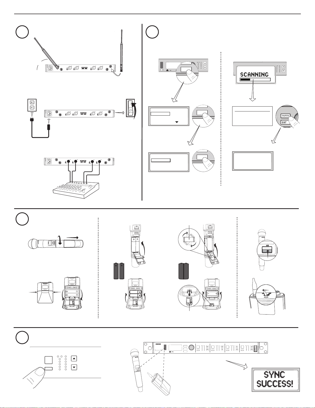
Quickstart Instructions
1 2
45°
b
gainaudio
control
RF
A B
OL
OL
ENTER
EXIT
SCAN
push
1-G: 01CH:03 TxOn
2-G: 01CH:06 TxOn
3-G: 01CH:08 TxOn
4-G: 01CH:12 TxOn
a
gainaudio
control
RF
A B
OL
OL
ENTER
EXIT
SCAN
push
GROUP SCAN
sync
a
150 mA
line
line
mic
mic
line
mic
A
line
mic
sync
power
b
line
line
mic
mic
line
line
mic
mic
Select RX TO SCAN
1 Receiver
2 Receiver
3 Receiver
SCAN COMPLETE
GROUP: 01
OPEN FREQ: 70
RX CHAN FOUND: 4
c
CHANNEL SCAN
line
line
mic
mic
line
line
mic
mic
CROUP SCAN
Deploy Completed
4 of 4
Channels Set
SYNC TX NOW
3
4
RX1
sync
a
a
b
95A15842
c
ULXD2
on
AA SB900
65A15224
b
control
RF
RX1 RX2 RX3 RX4
A B
ULXD4Q
Digital Wireless Receiver
gainaudio
RF
A B
OL
OL
2
D
X
L
U
n
o
<15 cm (6 in.)
ENTER
EXIT
SCAN
OL
OL
push
gainaudio
gainaudio
gainaudio
RF
RF
A B
A B
OL
OL
OL
OL
gainaudio
RF
power
A B
OL
OL
4
Receiver
ULXD4Q
Digital Wireless Receiver
1
IR
3
2
4
ENTER
EXIT
SCAN
6
control
push
7
5
8
RX1 RX2 RX3 RX4
SEL
sync
9
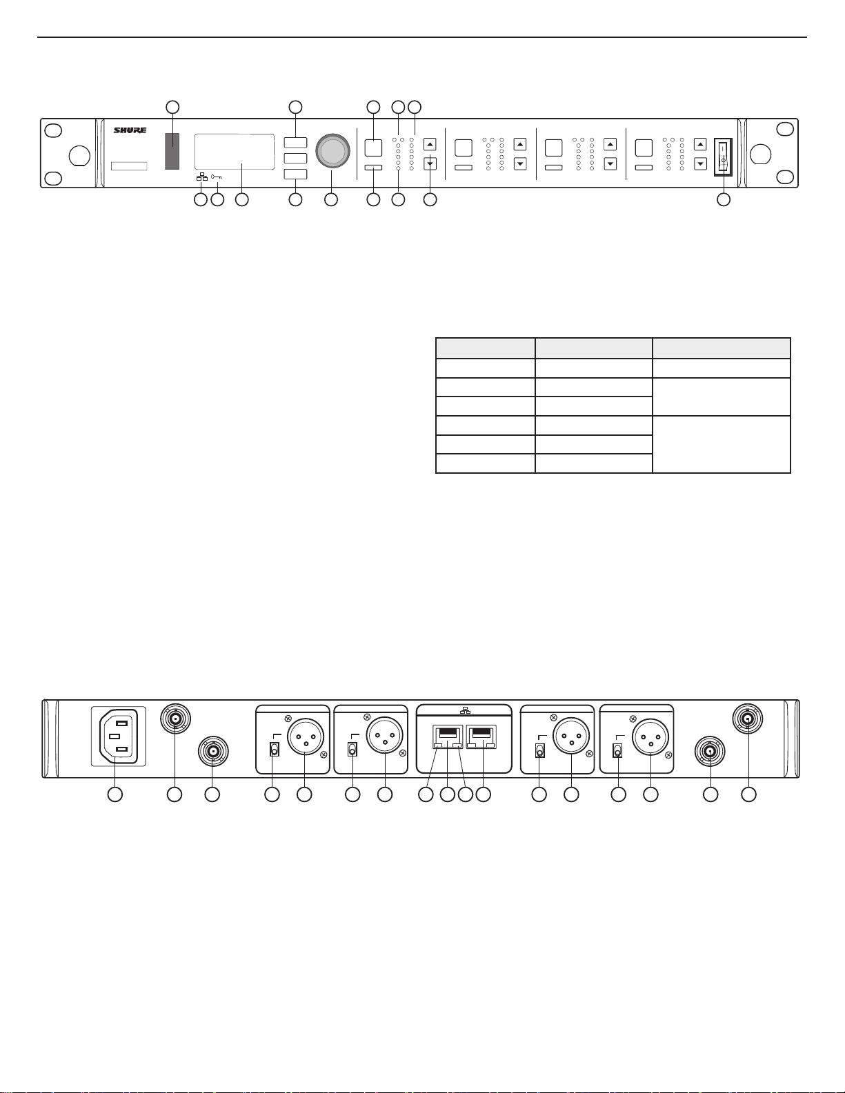
Front Panel
① Infrared (IR) Sync Window
Sends IR signal to the transmitter for sync.
② Network Icon
Illuminates when the receiver is connected with other Shure devices on the network.
IP Address must be valid to enable networked control.
③ Encryption Icon
Illuminates when AES-256 encryption is activated.
④ LCD Panel
Displays settings and parameters.
⑤ Scan Button
Press to find the best channel or group.
⑥ Menu Navigation Buttons
Use to navigate and select parameter menus.
⑦ Control Wheel
• Push to select a channel or menu item
• Turn to scroll through menu items or to edit a parameter value
⑧ Channel Select Button
Press to select a channel.
⑨ Sync Button
Press the sync button while the receiver and transmitter IR windows are aligned to
transfer settings from the receiver to the transmitter.
⑩ RF Diversity LEDs
Indicate antenna status:
• Blue = normal RF signal between the receiver and transmitter
• Red = interference detected
• Off = No RF connection between the receiver and transmitter
12
10
gainaudio
RF
A B
OL
OL
11
SEL SEL
sync sync sync
13
gainaudio
RF
A B
OL
OL
gainaudio
RF
A B
OL
OL
SEL
gainaudio
RF
A B
OL
power
OL
14
⑪ RF Signal Strength LEDs
Indicate the RF signal strength from the transmitter:
• Amber = Normal (-90 to -70 dBm)
• Red = Overload (greater than -25 dBm)
⑫ Audio LEDs
Indicate average and peak audio levels:
LED Audio Signal Level Description
Red (6) -0.1 dBFS Overload/ limiter
Yellow (5) -6 dBFS
Yellow (4) -12 dBFS
Normal peaks
Green (3) -20 dBFS
Signal PresentGreen (2) -30 dBFS
Green (1) -40 dBFS
Note: In Frequency Diversity mode, simultaneous blinking of the red and
yellow audio LEDs indicates that diversity audio has been routed to this
channel.
⑬ Gain Buttons
Press the ▲▼ gain buttons on the front of the receiver to incrementally adjust gain
from -18 to +42 dB.
⑭ Power Switch
Powers the unit on or off.
Note: the receiver will not output audio unless one blue LED is illuminated.
B
line
mic
3
1
2
line
mic
5
4 5 4
Back Panel
① AC Power Input
IEC Connector, 100 - 240 V AC.
② RF Antenna Diversity Input Jack (2)
For antenna A and antenna B.
③ RF Cascade Jack (2)
Passes the RF signal from Antenna A and Antenna B to one additional receiver.
④ Mic/Line Switch (one per channel)
Applies a 30 dB pad in mic position.
⑤ Balanced XLR Audio Output (one per channel)
Connect to a mic or line level input.
⑥ Network Status LED (Green)
One per network port.
• Off = no link
• On = network link
• Flashing = network link active
PrimarySecondary
line
mic
7 864
9
5
output 1output 2output 3output 4
line
mic
5
4
A
3
2
⑦ Ethernet/Dante Network Secondary Port
Connect to an Ethernet network to enable remote device control via WWB6
software. Also carries Dante digital audio and control signals for audio distribution,
monitoring, and recording - see Dante Network topic.
⑧ Network Speed LED (Amber)
One per network port.
• Off = 10/100 Mbps
• On = 1 Gbps
⑨ Ethernet/Dante Network Primary Port
Connect to an Ethernet network to enable remote device control via WWB6
software. Also carries Dante digital audio and control signals for audio distribution,
monitoring, and recording - see Dante Network topic.
5
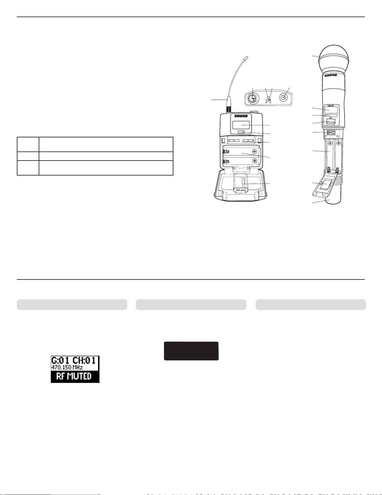
Transmitters
① Power LED
• Green = unit is powered on
• Red = low battery or battery error (see Troubleshooting)
• Amber = power switch is disabled
② On/Off Switch
Powers the unit on or off.
③ SMA Connector
Connection point for RF antenna.
④ LCD Display:
View menu screens and settings. Press any control button to activate the backlight.
⑤ Infrared (IR) Port
Align with the receiver IR port during an IR Sync for automated transmitter
programming.
⑥ Menu Navigation Buttons
Use to navigate through parameter menus and change values.
exit
enter Enters menu screens and confirms parameter changes
▼▲
⑦ Battery Compartment
⑧ AA Battery Adapter
⑨ Bodypack Antenna
⑩ Integrated Antenna
Acts as a 'back' button to return to previous menus or parameters without confirming a value change
Use to scroll through menu screens and to change parameter values
Requires Shure SB900 rechargeable battery or 2 AA batteries.
• Handheld: rotate and store in the battery compartment to use a Shure SB900
battery
• Bodypack: remove to accommodate a Shure SB900 battery
For RF signal transmission.
For RF signal transmission.
⑪
①⑫ ② ③
⑨
ULXD1
④
⑤
④
⑤
②
⑥
ULXD2
⑥
⑦
⑦
⑧
⑪ Microphone Cartridge
See Optional Accessories for a list of compatible cartridges.
⑫ TA4M Input Jack
Connects to a 4-Pin Mini Connector (TA4F) microphone or instrument cable.
⑧
⑩
on
Advanced Transmitter Features
RF MUTE
Use this to turn on a transmitter without interfering
with the RF spectrum.
Press and hold the exit button during power-on
until RF MUTED is displayed. To un-mute, restart
the transmitter.
Transmitter Input Clip MIC.OFFSET
The following warning displays on the receiver
LCD panel when the transmitter input is clipped:
Tx OVERLOAD
To correct, set MIC.OFFSET to 0 dB and if
necessary, attenuate the signal source.
If the source cannot be attenuated while using a
bodypack transmitter, select INPUT PAD from the
main menu to attenuate the input signal by 12 dB.
MIC.OFFSET compensates for signal level
differences between transmitters that share the
same receiver channel.
Set the offset gain on a low signal level
transmitter to match a louder transmitter: UTILITY
> MIC.OFFSET
Note: For normal gain adjustments, use the
receiver gain buttons.
6

6dB
Menu Screens
7
1
4
3
2
6
5
Receiver Channel
① Receiver Information
Use DEVICE UTILITIES > HOME INFO to change the home screen display.
② Gain Setting
−18 to +42 dB, or Mute.
③ Mic. Offset Indicator
Indicates offset gain is added to the transmitter.
④ Transmitter Settings
The following information cycles when a transmitter is tuned to the receiver's
frequency:
• Transmitter Type
• Input Pad (Bodypack only)
• RF Power Level
• Transmitter Lock Status
⑤ Battery Runtime Indicator
Shure SB900 battery: runtime is displayed in minutes remaining.
AA batteries: runtime is displayed with a 5-bar indicator.
⑥ TV Channel
Displays the TV channel that contains the tuned frequency.
⑦ High Density Mode Icon
Displayed when High Density mode is enabled.
Transmitter Setting Icons
Display Icon Transmitter Setting
Bodypack input is attenuated 12 dB
Offset gain is added to the transmitter
Lo 1 mW RF power level
Nm 10 mW RF power level
Hi 20 mW RF power level
M Menu is locked
P Power is locked
-No Tx-
No RF connection between a receiver and transmitter
or transmitter OFF
1
3 4
2
5
8
7
6
Transmitter
① Transmitter Information
Scroll ▲▼ at the home screen to change the display.
② Power Lock Indicator
Indicates power switch is disabled.
③ Battery Runtime Indicator
Shure SB900 battery: runtime is displayed in minutes remaining.
AA Batteries: runtime is displayed with a 5-bar indicator.
④ Menu Lock Indicator
Indicates menu navigation buttons are disabled.
⑤ Mic. Offset
Displays microphone offset gain value.
⑥ RF Power
Displays RF power setting or High Density mode icon (if enabled).
⑦ Bodypack Input Pad
The input signal is attenuated 12 dB.
⑧ Encryption Icon
Indicates encryption is enabled on the receiver and has been transferred to the
transmitter from a sync.
Receiver Home Screen
The home screen displays the following information for each receiver
channel:
• Group and Channel
• Transmitter Status: NoTx or TxOn, battery
icon/remaining battery life
Press the SEL button to access a channel
menu screen.
1 G:01 CH:01 TxOn
2 G:01 CH:02 TxOn
3 G:01 CH:03 TxOn
4 G:01 CH:04 TxOn
Home Screen Display Options
Receiver
The HOME INFO menu provides options to change the information shown on
the receiver home screen:
DEVICE UTILITIES > HOME INFO
Use the control wheel to select one of the following screen displays.
Transmitter
Home Screen: Press the ▲▼ arrows at the home menu to display one of
the following screens:
6dB
7
Batteries
12V OUT
150 mA
12V OUT
150 mA
15V 0.6A
line
mic
ULXD4
www.shure.com
power mic / line inst / auxantenna . B antenna . A
150 mA
ULXD4
Digital Wireless Receiver
sync
push
control
ENTER
EXIT
SCAN
RF
AB
OL
OL
gainpoweraudio
12V OUT
150 mA
line
mic
mic / line inst / aux
antenna . A
control
RF audio
gain
po
wer
push
SCAN
sync
EXIT
ENTER
power
on
n
o
2DXLU
on
ULXD1
ULXD1
push
EXIT
SCAN
push
EXIT
SCAN
ULXD4
Digital Wireless Receiver
sync
push
control
ENTER
EXIT
SCAN
RF
A B
OL
OL
gain poweraudio
ULXD4
Digital Wireless Receiver
sync
push
control
ENTER
EXIT
SCAN
RF
A B
OL
OL
gain poweraudio
push
EXIT
SCAN
!
!
!
!
!
!
!
!
!
!
!
!
!
!
!
!
!
!
!
!
!
!
!
!
!
!
!
!
a
b
on
ULXD2
12V OUT
150 mA
12V OUT
150 mA
15V 0.6A
line
mic
ULXD4
www.shure.com
power
mic / line
inst / aux
antenna . B
antenna . A
150 mA
150 mA
line
mic
ULXD4
www.shure.com
mic / line inst / aux
15V 0.6A
power
12V OUT
150 mA
12V OUT
150 mA
line
mic
ULXD4
www.shure.com
15V 0.6A
power
mic / line
inst / aux
antenna . B
antenna .
A
45°
SCAN COMPLETE
G:01 CH:21
485.775 MHz
Rssi: -118 dBm
on
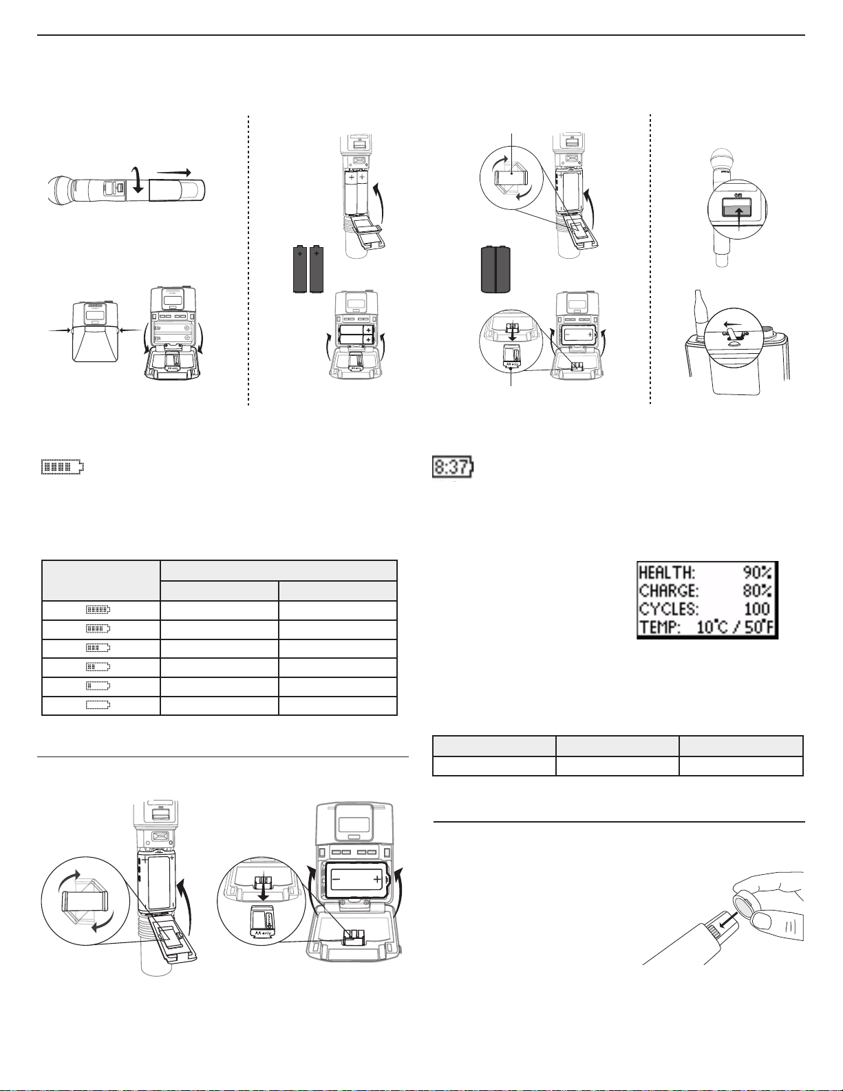
The transmitter runs on two AA batteries or the Shure SB900 rechargeable battery. Use the included AA battery adapter when using batteries other than the
Shure SB900.
a
AA SB900
AA Batteries
A 5-segment icon on the receiver and transmitter menu screens
indicates battery charge.
For accurate battery runtime monitoring, set the transmitter to the
appropriate battery type: UTILITY > BATTERY > SET.AA.TYPE.
b
95A15842
c
ULXD2
on
65A15224
Shure SB900 Rechargeable Battery
When using an SB900 rechargeable battery, the receiver and
transmitter home screens display the number of hours and
minutes remaining.
Detailed information for the SB900 is displayed in the receiver BATTERY
INFO menu and the transmitter menu: UTILITY > BATTERY > BATT. STATS
AA Alkaline Battery Runtime Chart (h:mm)
Battery Indicator
AA Battery Adapter
Handheld: Rotate and store the
adapter in battery door when using
Shure SB900
8
RF Power Setting
1/10 mW 20 mW
11:00 to 9:35 5:30 to 4:55
9:35 to 7:15 4:55 to 4:00
7:15 to 4:45 4:00 to 2:30
4:45 to 2:25 2:30 to 1:45
2:25 to 00:45 1:45 to 0:25
00:45 to 00:20 00:25 to 00:10
Bodypack: Remove the
adapter when using the
Shure SB900
HEALTH: Displays battery health as a
percentage of the charge capacity of
a new battery.
CHARGE: Percentage of a full charge
CYCLES: Number of times the battery
has been charged
TEMP: Battery temperature in Celsius
and Fahrenheit
Note: For additional rechargeable battery information, visit www.shure.com.
Shure SB900 Runtime
1 mW 10 mW 20 mW
>11 hours >11 hours >7 hour
Installing the Battery Contact Cover
Install the included battery contact cover
(65A15947) on the handheld transmitter
to prevent light reflection in broadcast
and performance situations.
1. Align the cover as shown.
2. Slide the cover over the battery
contacts until it is flush with the
transmitter body.
Note: Slide the cover off before inserting the transmitter in the battery charger.

gain power
Setting Gain
RF
AB
L
OL
gain poweraudio
RF
A B
OL
gainaudio
OL
Adjust gain at the receiver so that the average signal levels are solid green and yellow with peaks that occasionally trigger the red overload LED. Attenuate
the gain if the signal overloads repeatedly.
Set the XLR output to line-level when possible to optimize sound system noise performance.
System Gain Control
The gain control on the receiver sets the audio signal level for the entire system. This allows adjustments to be made during a live performance. It is not
necessary to change the gain on the transmitter (mic offset) to optimize the gain structure. Any required changes to gain should be made from the receiver.
Adjusting Gain
control
ENTER
IR
EXIT
SCAN
push
gain poweraudio
RF
A B
OL
OL
Press and hold a
Press the ▲▼ gain buttons on the front of the
gain button
receiver to incrementally adjust gain from -18 to +42
dB.
Reading the Audio Meter
Audio peaks illuminate the LEDs for 1 second hold time. The RMS
signal is displayed in real time.
audio
OL (Overload) LED: Illuminates red when the internal limiter is
OL
engaged, preventing digital clipping.
Mute
To mute the audio, use Shure Wireless Workbench® software or a thirdparty control device.
Receiver Output Level
The following table describes the typical total system gain from the audio input to the receiver outputs:
Large Gain Adjustments
or
Use the control wheel in
the AUDIO menu
ENTER
EXIT
SCAN
control
push
Output Jack System Gain (gain control = 0dB)
XLR (line setting) +24 dB
XLR (mic setting) -6 dB*
*This setting matches a typical wired SM58 audio signal level.
RF
Transmitter RF Power
Reference the following table for setting RF Power:
RF Power Setting System Range Application
1 mW 33 m (100 ft.)
10 mW 100 m (330 ft.) Typical setups
20 mW >100 m (330 ft.)
Note: Using the 20 mW setting decreases the transmitter battery runtime
and reduces the number of compatible systems.
For increased channel reuse at close
distances
For hostile RF environments or long-distance
applications
Interference Detection
Interference Detection monitors the RF environment for potential sources of
interference which can cause audio dropouts.
When interference is identified, the RF LEDs illuminate red and the following
warning displays on the receiver LCD panel.
If the warning display persists or the audio
drops out repeatedly, perform a Scan and
Sync at the first opportunity to find a clear
frequency.
9
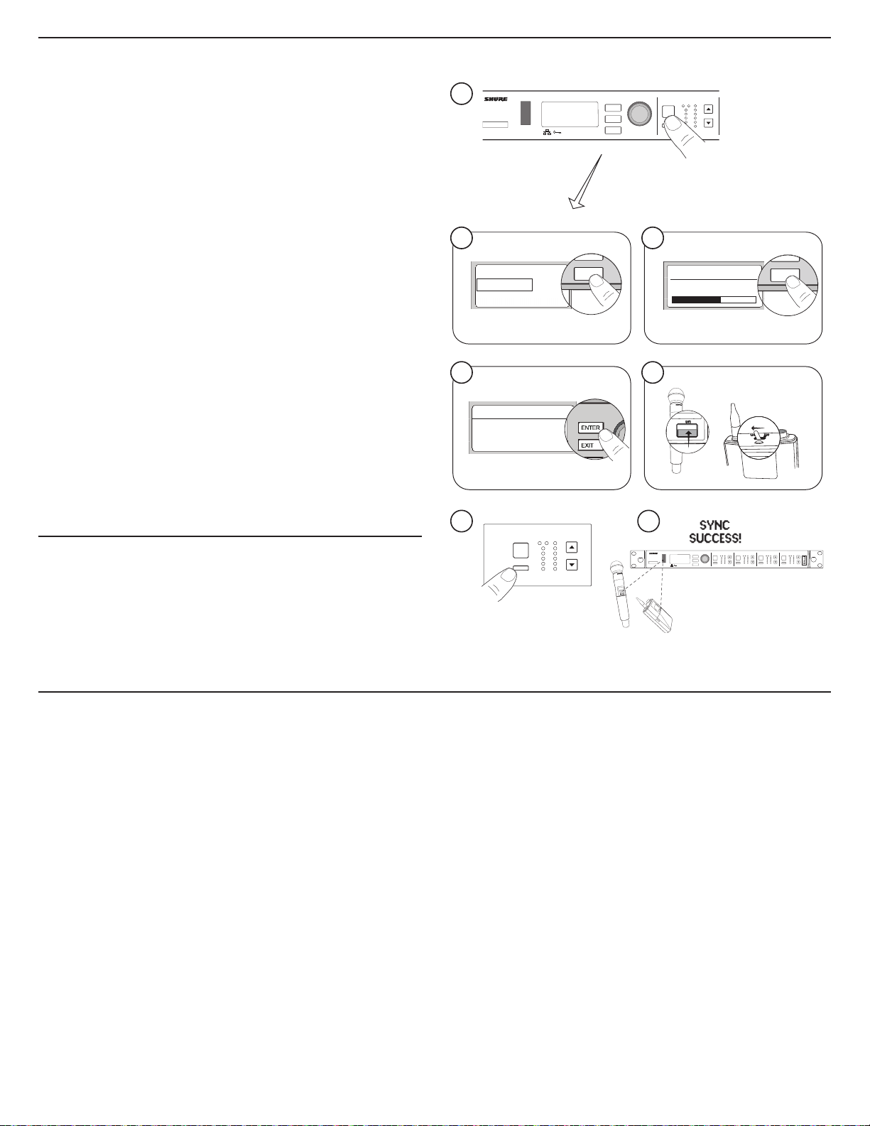
Scan and Sync
RF
A B
OL
OL
gainaudio
RF
A B
OL
OL
audio
RX2 RX3
on
ULXD2
!
!
!
!
!
!
!
!
!
!
!
!
!
!
!
!
!
!
!
!
!
!
!
!
!
!
!
!
EXIT
SCAN
EXIT
SCAN
Use this procedure to tune a receiver and transmitter to the best open channel.
Important! Before you begin:
Turn off all transmitters for the systems you are setting up. (This prevents
them from interfering with the frequency scan.)
Turn on the following potential sources of interference so they are operating
as they would be during the presentation or performance (the scan will
detect and avoid any interference they generate).
• Other wireless systems or devices
• Computers
• CD players
• Large LED panels
• Effects processors
1. Press the SEL button to select a channel.
2. Perform a channel scan on the receiver: SCAN > GROUP SCAN.
3. Press SCAN to start the scan. SCANNING appears on the LCD during the
scan.
4. After the scan completes, the receiver displays the group with the
most available frequencies. Press the flashing ENTER button to deploy
frequencies to each receiver channel.
5. Power on the ULXD transmitter.
6. Press the sync button on the receiver.
7. Align the IR windows until the receiver IR port illuminates red.
8. When complete, SYNC SUCCESS! appears. The transmitter and receiver
are now tuned to the same frequency.
Manual Frequency Selection
To manually adjust group, channel, or frequency:
1. Press SEL to choose a receiver channel and navigate to the RADIO
menu.
2. Use the control wheel to adjust the group, channel, or frequency.
3. Press ENTER to save changes.
1
ULXD4Q
Digital Wireless Receiver
ENTER
EXIT
SCAN
control
push
2
Channel Scan
Group Scan
4 5
SCAN COMPLETE
G:01 CH:21
485.775 MHz
Rssi: -118 dBm
6
RX1
sync
gainaudio
RF
A B
OL
OL
7
2
D
X
L
U
n
o
RF
RX1
A B
OL
SEL
3
Group Scan
SCANNING
ULXD2
on
ULXD4Q
Digital Wireless Receiver
<15 cm (6 in.)
gainaudio
OL
control
gainaudio
RF
RX1 RX2 RX3 RX4
A B
OL
ENTER
OL
EXIT
SCAN
push
gainaudio
gainaudio
RF
A B
OL
OL
gainaudio
RF
RF
power
A B
A B
OL
OL
OL
OL
Multiple System Setup
A setup using networked receivers is the fastest and easiest way to distribute the best open channel to each system. See Networking ULX-D Receivers for
networking details.
Note: Networked receivers must all be within the same frequency band.
Networked Receivers
1. Turn on all receivers.
2. Conduct a group scan on the first receiver to find available frequencies in
each group: SCAN > GROUP SCAN.
3. Press ENTER to accept the group number and automatically assign the
next best channel to each receiver on the network. The receiver LEDs will
flash when a frequency has been assigned.
4. Turn on a transmitter and sync to the receiver.
Important! Leave the transmitter on and repeat this step for each
additional system.
10
Non-networked Receivers
1. Turn on all receivers.
2. Conduct a group scan on the first receiver to find available frequencies in
each group: SCAN > SCAN > GROUP SCAN > SCAN
3. When the scan is complete, use the control wheel to scroll through
each group. Press ENTER to select a group that has enough available
frequencies for all channels in the system.
4. Sync a transmitter to each receiver channel.
Important! Leave all transmitters on use the following steps to set up
additional receiver channels:
1. Set each additional receiver channel to the same group as the first
receiver: RADIO > G:
2. Conduct a channel scan to find available frequencies within the group:
SCAN > SCAN > CHANNEL SCAN > SCAN
3. When the scan is complete, press ENTER to assign frequencies to each
receiver channel.
4. Sync a transmitter to each receiver channel.
 Loading...