


Shure Brothers Incorporated
222 Hartrey Avenue
Evanston IL 60202-3696 U.S.A.
UHF Wireless System
USER GUIDE SUPP LE ME NT UB (692–716 MHz)
CONTENTS
SPECIFICATIONS 2. . . . . . . . . . . . . . . . . . . . . . . . . . . . . . . . . . . . . . . . . . . . . . . .
Furnished Accessories 4. . . . . . . . . . . . . . . . . . . . . . . . . . . . . . . . . . . . . . . . .
Optional Accessories 5. . . . . . . . . . . . . . . . . . . . . . . . . . . . . . . . . . . . . . . . . . .
Replacement Parts 5. . . . . . . . . . . . . . . . . . . . . . . . . . . . . . . . . . . . . . . . . . . . .
FREQUENCY SELECTION GUIDE 6. . . . . . . . . . . . . . . . . . . . . . . . . . . . . . . . . .
Compatibility Groups 6. . . . . . . . . . . . . . . . . . . . . . . . . . . . . . . . . . . . . . . . . . .
E1999, Shure Brothers Incorporated
27A8694 (SE)
Printed in U.S.A.

SPECIFICATIONS
RF Carrier Frequency Range
692–716 MHz
Working Range
152.4 m (500 ft), minimum, under typical conditions; 487.6 m (1600 ft ) line of sight
NOTE: Actual working range depends on RF signal absorption, ref lection and
interference
Audio Frequency Response
45 to 15,000 Hz, ±2 dB. NOTE: Overall system frequency response depends on the
microphone element
Gain Adjustment Range
UC1B: –6 to 34 dB
UC2B: –6 to 26 dB
Modulation
±45kHz deviation compressor-expander system with pre-and de-emphasis
RF Power Output
UC1B: 50 mW effective radiated power , typical
UC2B: 20 mW effective radiated power , typical
Dynamic Range
>100 dB, A-weighted
Receiver Audio Output Level (Maximum)
+5 dBu typical, unbalanced output
+14 dBu typical, balanced output
RF Sensitivity
UC4B: –108 dBm at 12 dB SINAD
Image Rejection
90 dB typical
Spurious Rejection
70 dB typical
Ultimate Quieting (ref. 45 kHz deviation)
>100 dB, A-weighted
Audio Polarity
Positive pressure on microphone diaphragm (or positive voltage applied to tip of
WA302 phone plug) produces positive voltage on pin 2 with respect to pin 3 of
low impedance output and the tip of the high impedance
System Distortion (ref. ±45 kHz deviation, 1 kHz modulation)
0.4% T otal Harmonic Distortion typical
Power Requirements
UC1 B , U C2B: 9 V a lkalin e batt e ry (D u racell MN1604 recom mended); Nicad optional
UC4B: 15 Vdc , 600 mA 50/60 Hz
Power Consumption: 600 mA x 15 V , maximum
Transmitter Battery Life (Typical)
8 hours (with Duracell MN1604 9V alkaline battery)
Operating Temperature Range
-7° to 49° C (20° to 120° F) NOTE: Battery characteristics may limit this range
Overall Dimensions
UC1B: 99.06 mm L x 63.50 mm W x 22.86 mm D (3–29/32 L x 2–1/2 W x 29/32 in. D)
UC2B/58:247.30 mm L x 50.8 mm Dia. (9–1/2 L x 2 in. Dia.)
UC2B/BETA 58: 241.30 mm L x 50.80 mm Dia. (9–1/2 L x 2 in. Dia.)
UC2B/87:215.90 mm x 50.80 mm Dia. (8–1/2 L x 2 in. Dia.)
UC2B/BETA 87: 215.90 mm L x 50.8 mm Dia. (8–1/2 L x 2 in. Dia.)
UC4B: 44.50 mm H x 197.40 mm W x 214.30 mm D (1–3/4 L x 7.77 W x 8.44 in. D)
1
/4-inch output
2
Net Weight
UC1B: 73.50 g (2.59 oz.) without battery
UC2B/58, U2/BET A 58: 31 1.9 g (11 oz.) without battery
UC2B/87, U2/BETA 87: 198.5 g (7 oz.) without battery
UC4B: 1.22 kg (2 lbs, 1 1 oz.)
Certification
UC1B, UC2B: Type Accepted under FCC Parts 74. Certified by IC in Canada under
TRC-78. FCC ID for UC1B: DD4UC1B. FCC ID for UC2B: DD4UC2B.
UC4B: UL and cUL Listed to UL 813 and CSA C22.2 No. 1. VDE Certified to EN 60 950.
Approved under the Notification provision of FCC Part 15; Certified by IC in Canada
under TRC-78. FCC ID: DD4UC4B.
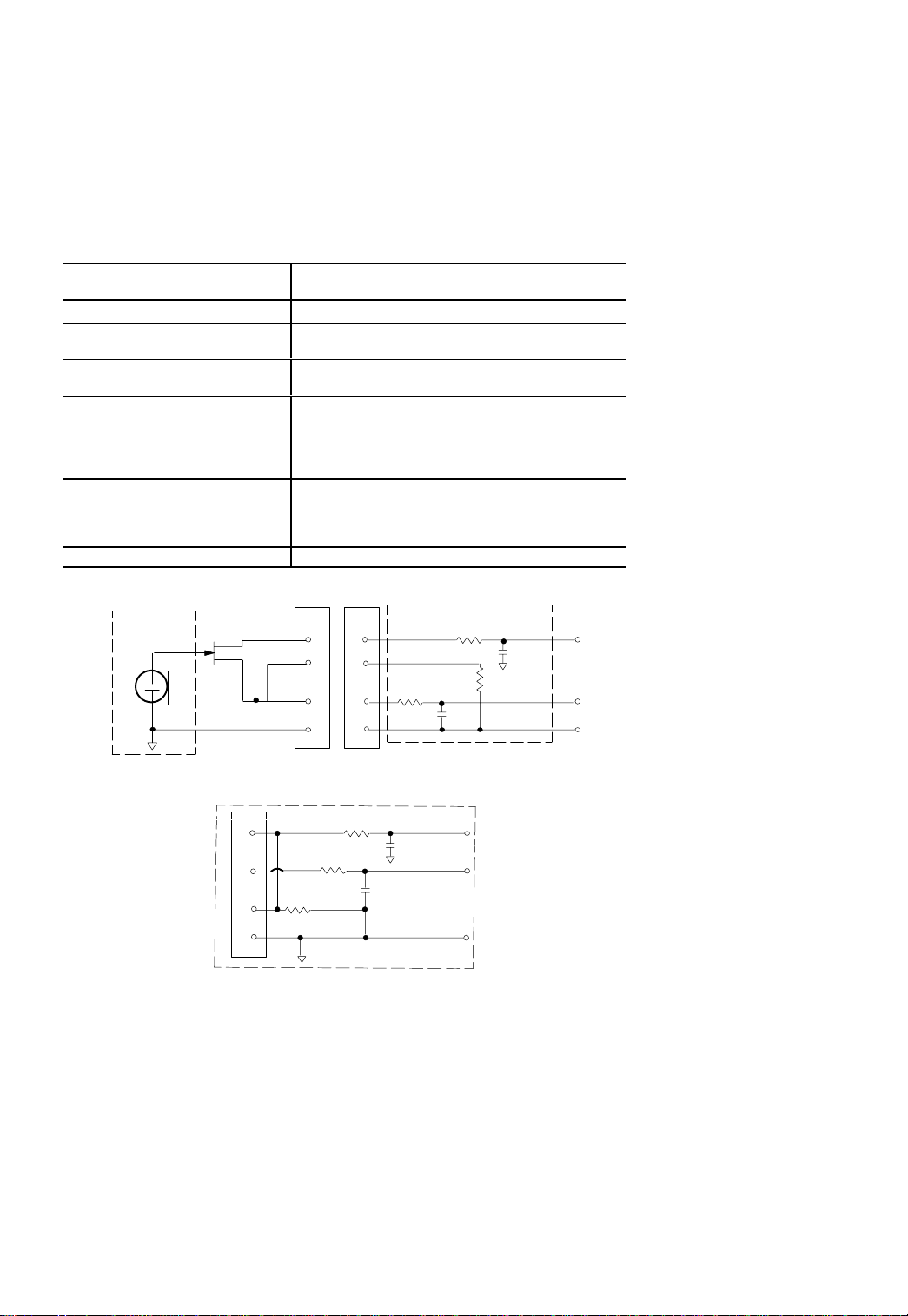
UC1B Transmitter Input (Figure 1)
Connector:
Input Configuration:
Actual Impedance:
Maximum Input Level:
9 Vp–p (10 dBV) for 1% THD at minimum gain
Switchcraft T A4F Tini Q.G. or
LEMO connector (optional)
Unbalanced, active
18 kΩ with lavalier microphone
1 MΩ with instrument cable
setting using 1 kHz signal.
Pin 1: Tied to Ground
T A4F T ini Q.G. Connector Pin
Assignments:
Pin 4: Tied thru 20kΩ Resistor to Ground.
Pin 2: Tied to +5 V
Pin 3: Tied to Audio
(On instrument adapter cable, Pin 4 floats)
Pin 1: Tied to Pin 3 and 10 kΩ to Ground
LEMO Connector
Pin Assignments:
Pin 2: +5V
Pin 3: Tied to Pin 1
Pin 4: Tied to Shield (Ground for Positive Bias)
V o ltag e for Remote Power:
+5 V supplied to microphone cartridge
UC1B MIC JACK
BOARD
500 Ω
27 pF
500 Ω
1
20K Ω
27 pF
UC1B
MICROPHONE
ELEMENT
2
2
4
4
3
3
1
NOTE: LAVALIER MIC TIES PINS 3 AND 4 T OGETHER; GUITAR CABLE DOES NOT.
UC1BL (LEMO 4 PIN) MIC JACK
BOARD
1
2
10K Ω
3
4
499 Ω
499 Ω
FIGURE 1
3
AUDIO
27 pF
BIAS
27 pF
SHIELD
+5 V
AUDIO
GROUND

UC1B Transmitter Output
Antenna:
Actual Impedance:
Nominal Output Level:
Maximum Output Level:
Flexible 1/4 wave wire
50 Ω
+16 dBm
+17 dBm
UC2B Transmitter Input
Input Configuration: Unbalanced, active
Actual Impedance:
Maximum Input Level: 9 Vp–p (10 dBV) for 1% THD at minimum gain setting
25 kΩ
using 1 kHz signal.
UC2B Transmitter Output
Antenna:
Actual Impedance:
Nominal Output Level:
Maximum Output Level:
Internal dipole
50 Ω
+12 dBm, radiated
+12 dBm, conducted
UC4B Receiver Input
Connector: Antenna Power Input
Connector T ype: BNC dc style
Actual Impedance: 50 Ω ––
Nominal Input Level: –95 to –30 dBm 15 Vdc
Maximum Input Level: +6 dBm
17 Vdc
(–20 dBm recommended)
Pin Assignments: Shell = Ground
Center pin positive
Center = Signal
UC4B Receiver Output
Connector: High Z Audio Low Z Audio
Output Configurati on:
Actual Impedance:
Nominal Input Level:
Output Level:
Pin Assignments:
Unbalanced Balanced
1 kΩ 44Ω
–– ––
5 dBu m a x i m u m 14 dBu maximum
Tip = Hot
Ring/ Sleeve = Gnd
1 = Ground
2 = Hot
3 = Hot
FURNISHED ACCESSORIES
Microphone Stand Adapter (UC2B) WA370A. . . . . . . . . . . . . . . . . . . . . . . . . . . . . . . . . . . .
Zipper Bag (UC1B) 26A13. . . . . . . . . . . . . . . . . . . . . . . . . . . . . . . . . . . . . . . . . . . . . . . . . . .
Zipper Bag (UC2B) 26A14. . . . . . . . . . . . . . . . . . . . . . . . . . . . . . . . . . . . . . . . . . . . . . . . . . .
Screwdriver 80A498. . . . . . . . . . . . . . . . . . . . . . . . . . . . . . . . . . . . . . . . . . . . . . . . . . . . . . . .
1/4 Wave Antenna UA400. . . . . . . . . . . . . . . . . . . . . . . . . . . . . . . . . . . . . . . . . . . . . . . . . . .
4

OPTIONAL ACCESSORIES
Instrument Adapter Cable (UC1B) WA302. . . . . . . . . . . . . . . . . . . . . . . . . . . . . . . . . . . . . .
Switchcraft TA4F Female 4–Pin Connector (UC1B) WA330. . . . . . . . . . . . . . . . . . . . . . .
In-Line Audio Switch (UC1B) WA360. . . . . . . . . . . . . . . . . . . . . . . . . . . . . . . . . . . . . . . . . .
1.8 Meter (6 ft) Receiver-Mixer Cable (1/4” phone to XLR) WA410. . . . . . . . . . . . . . . . . .
0.6 Meter (2 ft.) Antenna Extension Cable UA802. . . . . . . . . . . . . . . . . . . . . . . . . . . . . . .
7.6 Meter (25 ft) Antenna Extension Cable UA825. . . . . . . . . . . . . . . . . . . . . . . . . . . . . .
15.2 (50 ft) Meter Antenna Extension Cable UA850. . . . . . . . . . . . . . . . . . . . . . . . . . . . .
In–Line Active Remote Antenna Kit (800 – 830 MHz) UA830C. . . . . . . . . . . . . . . . . . . .
Antenna/Power Distribution System, 230 V ac UA845–MB. . . . . . . . . . . . . . . . . . . . . . . .
Directional Antenna for UC4B Receiver UA870C. . . . . . . . . . . . . . . . . . . . . . . . . . . . . . . .
Remote Mute Switch for UC1B UA101. . . . . . . . . . . . . . . . . . . . . . . . . . . . . . . . . . . . . . . .
Passive Antenna Splitter/Combiner UA220. . . . . . . . . . . . . . . . . . . . . . . . . . . . . . . . . . . . .
1/2 Wave Omnidirectional Antenna for UC4B Receiver UA820A. . . . . . . . . . . . . . . . . . .
Remote Mount Antenna Kit UA500. . . . . . . . . . . . . . . . . . . . . . . . . . . . . . . . . . . . . . . . . . .
Front Mount Antenna Kit UA600. . . . . . . . . . . . . . . . . . . . . . . . . . . . . . . . . . . . . . . . . . . . . .
REPLACEMENT PARTS
Hardware Kit (screwdriver, mounting feet, cable clamps) 90VX1371. . . . . . . . . . . . . . .
Bulkhead Adapters for Front–Mounting Antennas 95A8647. . . . . . . . . . . . . . . . . . . . . . .
15 Vdc Power Cord (230 V AC) PS40E. . . . . . . . . . . . . . . . . . . . . . . . . . . . . . . . . . . . . . . .
SM58 Cartridge with Grille (UC2B/58) R158. . . . . . . . . . . . . . . . . . . . . . . . . . . . . . . . . . . .
BET A 58A Cartridge with Grille (UC2B/BETA 58) R179. . . . . . . . . . . . . . . . . . . . . . . . . . .
SM87 Cartridge with Grille (UC2B/87) R165. . . . . . . . . . . . . . . . . . . . . . . . . . . . . . . . . . . .
BET A 87 Cartridge with Grille (UC2B/BETA 87) R166. . . . . . . . . . . . . . . . . . . . . . . . . . . .
Matte Silver Grille (UC2B/58) RK143G. . . . . . . . . . . . . . . . . . . . . . . . . . . . . . . . . . . . . . . . .
Matte Silver Grille (UC2B/BETA 58) RK265G. . . . . . . . . . . . . . . . . . . . . . . . . . . . . . . .
Matte Silver Grille (UC2B/BETA 87 RK313G. . . . . . . . . . . . . . . . . . . . . . . . . . . . . . . . .
Black Grille (UC2B/87) RK214G. . . . . . . . . . . . . . . . . . . . . . . . . . . . . . . . . . . . . . . . . . . . . .
Black Grille (UC2B/BET A 58) RK323G. . . . . . . . . . . . . . . . . . . . . . . . . . . . . . . . . . . . . . . . .
Black Grille (UC2B/BET A 87) RK324G. . . . . . . . . . . . . . . . . . . . . . . . . . . . . . . . . . . . . . . . .
Belt Clip (UC1B) 44A8013. . . . . . . . . . . . . . . . . . . . . . . . . . . . . . . . . . . . . . . . . . . . . . . . . . . .
Mounting Brackets, Long 53A8458. . . . . . . . . . . . . . . . . . . . . . . . . . . . . . . . . . . . . . . . . . . .
Mounting Brackets, Short 53A8454. . . . . . . . . . . . . . . . . . . . . . . . . . . . . . . . . . . . . . . . . . . .
Mounting Brackets, Link 31A8138. . . . . . . . . . . . . . . . . . . . . . . . . . . . . . . . . . . . . . . . . . . . .
UC4B Logic Connector (Phoenix) 95A8580. . . . . . . . . . . . . . . . . . . . . . . . . . . . . . . . . . . . .
5

FREQUENCY SELECTION GUIDE
C
H
N
N
E
The Shure UC Wireless System is designed for maximum flexibility and versatility
in a variety of applications. Up to 16 Shure UHF Wireless Systems can be operated
simultaneously in a single installation using the frequency compatibility groups.
Please contact Shure Brothers Incorporated if you need additional information or assistance in frequency selection and setup.
Compatibility Groups
The Shure UC Wireless System includes 10 groups of compatible channels. If you are
using more than one receiver in the same area, we recommend that you set the receivers
to different frequencies within the same group.
Compatible Frequency List
The following table lists the frequencies in each of the ten compatibility groups.
GROUP
GRP 1 GRP 2 GRP 3 GRP 4 GRP 5 GRP 6 GRP 7 GRP 8 GRP 9 GRP 10
1 692.500 692.125 692.250 698.250 692.500 692.125 692.125 715.625 715.500 715.125
2 693.375 692.625 695.125 698.875 693.250 693.500 693.125 714.625 714.250 714.125
3 694.500 693.375 695.875 700.000 694.250 694.125 693.625 714.000 712.750 713.625
4 695.000 694.375 697.125 700.625 695.000 695.125 694.625 713.125 712.000 711.875
5 697.000 695.125 698.625 701.500 695.500 695.750 695.875 712.000 710.875 711.125
6 698.000 698.875 699.875 702.000 696.250 697.000 696.500 710.250 710.375 709.875
7 699.250 699.375 700.625 702.750 697.250 697.750 697.875 708.125 708.250 709.000
A 8 699.750 700.625 701.625 703.750 698.000 699.125 698.875 707.625 707.125 708.375
9 702.875 703.125 702.375 704.375 704.500 700.125 700.500 706.750 704.125 707.375
N
10 703.750 704.625 703.625 709.000 706.000 701.625 701.500 706.250 702.500 706.625
11 705.500 706.375 704.375 709.500 706.750 702.250 703.375 703.625 700.625 705.125
12 707.500 707.125 708.375 710.250 707.250 710.125 703.875 702.625 699.000 700.875
13 708.500 707.625 709.375 711.250 708.750 710.625 705.875 701.875 698.125 700.000
L
14 709.000 708.375 709.875 711.875 709.500 711.500 706.875 699.875 697.625 699.375
15 709.750 710.875 710.750 712.750 711.250 712.125 707.625 696.375 695.875 697.625
16 710.250 711.500 711.875 713.250 712.000 713.125 708.125 695.875 694.875 696.875
6

7

The Sound of Professionals...Worldwide r
Shure Brothers Incorporated
222 Hartrey Avenue
Evanston, IL 60202–3696 U.S.A.
8
 Loading...