

Page 1

Shure SLX Wireless
Systems
English . . . . . . . . . . . . . . . . . . . . . . . . . . . . . . . . . . . . . . . . . . . . . . . . . . . . . . . . . 2
Français . . . . . . . . . . . . . . . . . . . . . . . . . . . . . . . . . . . . . . . . . . . . . . . . . . . . . . . . .
Deutsch. . . . . . . . . . . . . . . . . . . . . . . . . . . . . . . . . . . . . . . . . . . . . . . . . . . . . . . . . .
Español. . . . . . . . . . . . . . . . . . . . . . . . . . . . . . . . . . . . . . . . . . . . . . . . . . . . . . . . . .
Italiano . . . . . . . . . . . . . . . . . . . . . . . . . . . . . . . . . . . . . . . . . . . . . . . . . . . . . . . . . .
Portuguese . . . . . . . . . . . . . . . . . . . . . . . . . . . . . . . . . . . . . . . . . . . . . . . . . . . . . . .
Japanese . . . . . . . . . . . . . . . . . . . . . . . . . . . . . . . . . . . . . . . . . . . . . . . . . . . . . . . .
Chinese. . . . . . . . . . . . . . . . . . . . . . . . . . . . . . . . . . . . . . . . . . . . . . . . . . . . . . . . . .
Russian. . . . . . . . . . . . . . . . . . . . . . . . . . . . . . . . . . . . . . . . . . . . . . . . . . . . . . . . . .
Korean . . . . . . . . . . . . . . . . . . . . . . . . . . . . . . . . . . . . . . . . . . . . . . . . . . . . . . . . . .
Arabic . . . . . . . . . . . . . . . . . . . . . . . . . . . . . . . . . . . . . . . . . . . . . . . . . . . . . . . . . . .
1
Page 2

Shure SLX Wireless
Shure SLX Wireless
Smart, Hard-working
Wireless
Congratulations! Welcome to Shure SLX Wireless. Your new system is rugged, reliable, easy to set
up and operate, and produces outstanding audio clarity. Whether you’re a vocalist, guitarist, or instrumentalist, your SLX Wireless system will show you how easy wireless can be, and how good wireless
can sound.
This user guide and the Quick Setup guide included with your system will tell you all you need to
know to get your system working right away.
Welcome to the world of SLX: smart, hard-working wireless.
Frequency Band Selection
Most countries closely regulate the radio frequencies used in the transmission of wireless information. These regulations state which devices can use which frequencies, and help to limit the amount
of RF (radio frequency) interference in all wireless communications.
To be flexible enough to operate worldwide, SLX receivers are available in multiple dedicated frequency models. Each dedicated frequency range, or band, spans up to 24 MHz of the wireless broadcast spectrum. Available bands are:
H5: 518–542 MHz
J3: 572–596 MHz
L4: 638–662 MHz
P4: 702–726 MHz
To facilitate system setup and protect against RF interference, each system comes with multiple
predefined frequency groups and channels.
When using a single SLX system, the operating frequency will generally not have to be changed.
In an installation with multiple receiver/transmitter systems, each system must operate on a separate
channel. The group and channel system provides an optimum frequency spread when using multiple
systems.
Within a single frequency band, up to 12 individual transmitter/receiver systems may be used in a
single installation. In regions where additional frequency bands are available, it is possible to operate
up to 20 systems simultaneously. Check with your local Shure retailer for information on which bands
are available in your area.
R5: 800–820 MHz
S6: 838–865 MHz
JB: 806–810 MHz
Q4: 740–752 MHz
What Do You Want to Do
Now?
Learn about your SLX4 Receiver
Power, lock/unlock, front and back panel features: See “SLX4 Receiver Features” on page 5 and
“SLX4 Receiver Programming” on page 9.
Learn about your SLX2 Handheld Transmitter
Power, mute, gain, lock/unlock, other features: See “SLX2 Handheld Transmitter” on page 6 and
“SLX1 and SLX2 Transmitter Programming” on page 10.
Learn about your SLX1 Bodypack Transmitter
Power, mute, gain, lock/unlock, other features: See “SLX1 Bodypack Transmitter” on page 7 and
“SLX1 and SLX2 Transmitter Programming” on page 10.
Program your SLX Receiver and Transmitter
Frequency selection, LCD features, using the select and menu buttons: See “SLX Programming”
on page 9.
Learn how to use multiple systems in a single installation
See “Multiple System Setup” on page 8.
Troubleshoot your SLX system
See “Troubleshooting” on page 12.
2
Page 3

English
Table of Contents
System Components . . . . . . . . . . . . . . . . . . . . . . . . . . . . . . . . . . . . . . . . . . . . . . 4
SLX4 Receiver Features . . . . . . . . . . . . . . . . . . . . . . . . . . . . . . . . . . . . . . . . . . .5
SLX2 Handheld Transmitter . . . . . . . . . . . . . . . . . . . . . . . . . . . . . . . . . . . . . . . . 6
SLX1 Bodypack Transmitter. . . . . . . . . . . . . . . . . . . . . . . . . . . . . . . . . . . . . . . .7
Single System Setup . . . . . . . . . . . . . . . . . . . . . . . . . . . . . . . . . . . . . . . . . . . . . . 8
Multiple System Setup . . . . . . . . . . . . . . . . . . . . . . . . . . . . . . . . . . . . . . . . . . . .8
SLX Programming . . . . . . . . . . . . . . . . . . . . . . . . . . . . . . . . . . . . . . . . . . . . . . . .9
SLX4 Receiver Programming . . . . . . . . . . . . . . . . . . . . . . . . . . . . . . . . . . . . . . 9
SLX1 and SLX2 Transmitter Programming . . . . . . . . . . . . . . . . . . . . . . . . . . . 10
The Master Frequency List . . . . . . . . . . . . . . . . . . . . . . . . . . . . . . . . . . . . . . .10
Rack-Mounting SLX Receivers. . . . . . . . . . . . . . . . . . . . . . . . . . . . . . . . . . . . . 11
Receiver Volume Control . . . . . . . . . . . . . . . . . . . . . . . . . . . . . . . . . . . . . . . . .12
Tips for Improving System Performance . . . . . . . . . . . . . . . . . . . . . . . . . . . . 12
Troubleshooting . . . . . . . . . . . . . . . . . . . . . . . . . . . . . . . . . . . . . . . . . . . . . . . . 12
Specifications . . . . . . . . . . . . . . . . . . . . . . . . . . . . . . . . . . . . . . . . . . . . . . . . . .13
Replacement Parts and Accessories. . . . . . . . . . . . . . . . . . . . . . . . . . . . . . . .14
Microphone Specification . . . . . . . . . . . . . . . . . . . . . . . . . . . . . . . . . . . . . .15–17
Frequency Ranges. . . . . . . . . . . . . . . . . . . . . . . . . . . . . . . . . . . . . . . . . . . . 18–20
Regulatory Statements . . . . . . . . . . . . . . . . . . . . . . . . . . . . . . . . . . . . . . . . . . .21
Patent numbers 6,597,301, 5,794,125, and 5,692,057.
3
Page 4
Shure SLX Wireless
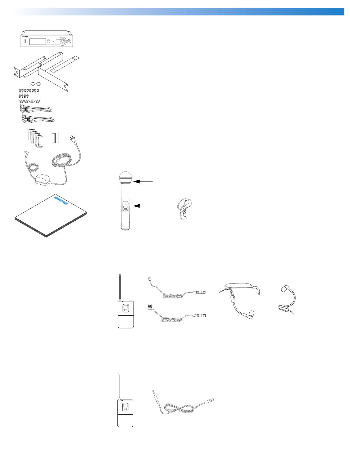
System Components
-
+
-
+
All systems include:
●
SLX4 receiver
●
Rack mount supplies
•Short rack ear
• Long rack ear
• Link bar to mount to similar receiver
• Extension cables and connectors for front-mounting antennas
• 8 rack ear screws
• 4 rack mount screws with washers
• 2 antenna hole plugs
●
Protective bumpers
●
2 AA batteries (4 in combo systems)
●
Power supply
●
User guide
Vocalist system includes:
●
Microphone Head (choice of SM58®, SM86, Beta 58A®, Beta 87A, or Beta 87C)
●
SLX2 handheld transmitter
●
Microphone clip
SLX
User Guide
®
Wireless Systems
SLX
Lavalier, Headworn, and Instrument systems include:
●
SLX1 bodypack transmitter
●
Microphone (choice of WL93 , WL184 or WL185 , WH30 , or Beta 98H/C )
Guitar system includes:
●
SLX1 bodypack transmitter
●
1/4” to mini 4-pin guitar cable
4
Page 5
SLX4 Receiver Features
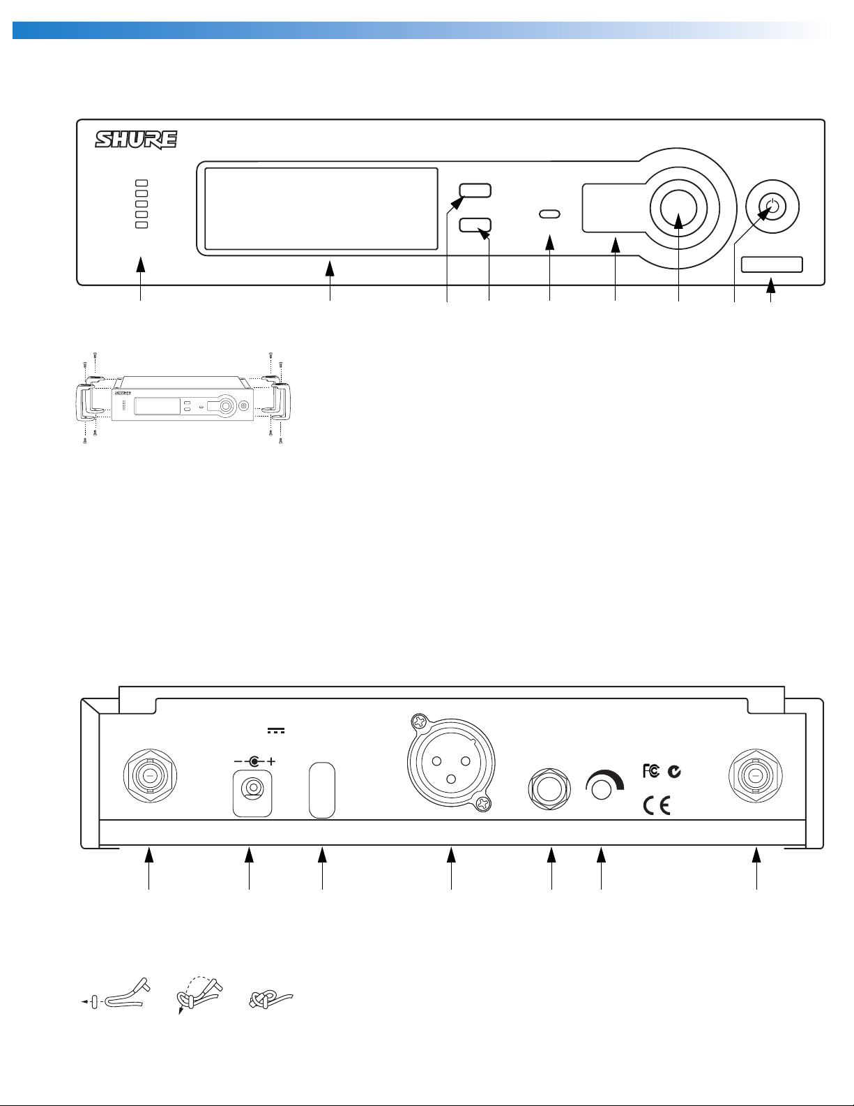
Front Panel
English
SLX4
menu
audio
select ready sync
H5 518-542 Mhz
Audio LED
Indicates strength of incoming audio
signal.
LCD panel
See “SLX Programming” on page 9.
Menu switch
Press to scroll through menu options.
See “SLX Programming” on page 9.
Select switch
Press to select the currently displayed
menu option. See “SLX Programming”
on page 9.
Sync Ready Indicator
Illuminates when frequencies of
receiver and transmitter are
synchronized. See “SLX Programming”
on page 9.
Infrared (IR) port
Broadcasts IR signal to transmitter to
synchronize frequencies.
Sync Button
Press to initiate IR connection between
receiver and transmitter. See “SLX
Programming” on page 9.
On/Off switch
Tap to turn on, hold to turn off.
Frequency Band
Indicates the name and range of
receiver frequency band.
Adding protective bumpers
Recommended if receiver is not rack
mounted. Use supplied screws. For
rack-mounting instructions, See “Rack-
Mounting an SLX Receiver” on
page 11.
Back Panel
ANTENNA B
12–18 V
160 mA
POWER
BALANCED
LOW Z
MIC OUT LINE OUT VOLUME ANTENNA A
Antenna jack B
AC adapter jack
Adapter cord tie-off
Follow steps shown to secure cord to
receiver body
XLR output jack
SHURE INCORPORATED
UNBALANCED
HIGH Z
NILES, IL 60714
SLX4 RECEIVER
N108
IC: 616A–SLX4
1/4” output jack
Volume adjustment dial
Decreases receiver output level. See
“Receiver Volume Control” on page 12.
Antenna jack A
5
Page 6
SLX2 Handheld Transmitter
SLX
Shure SLX Wireless
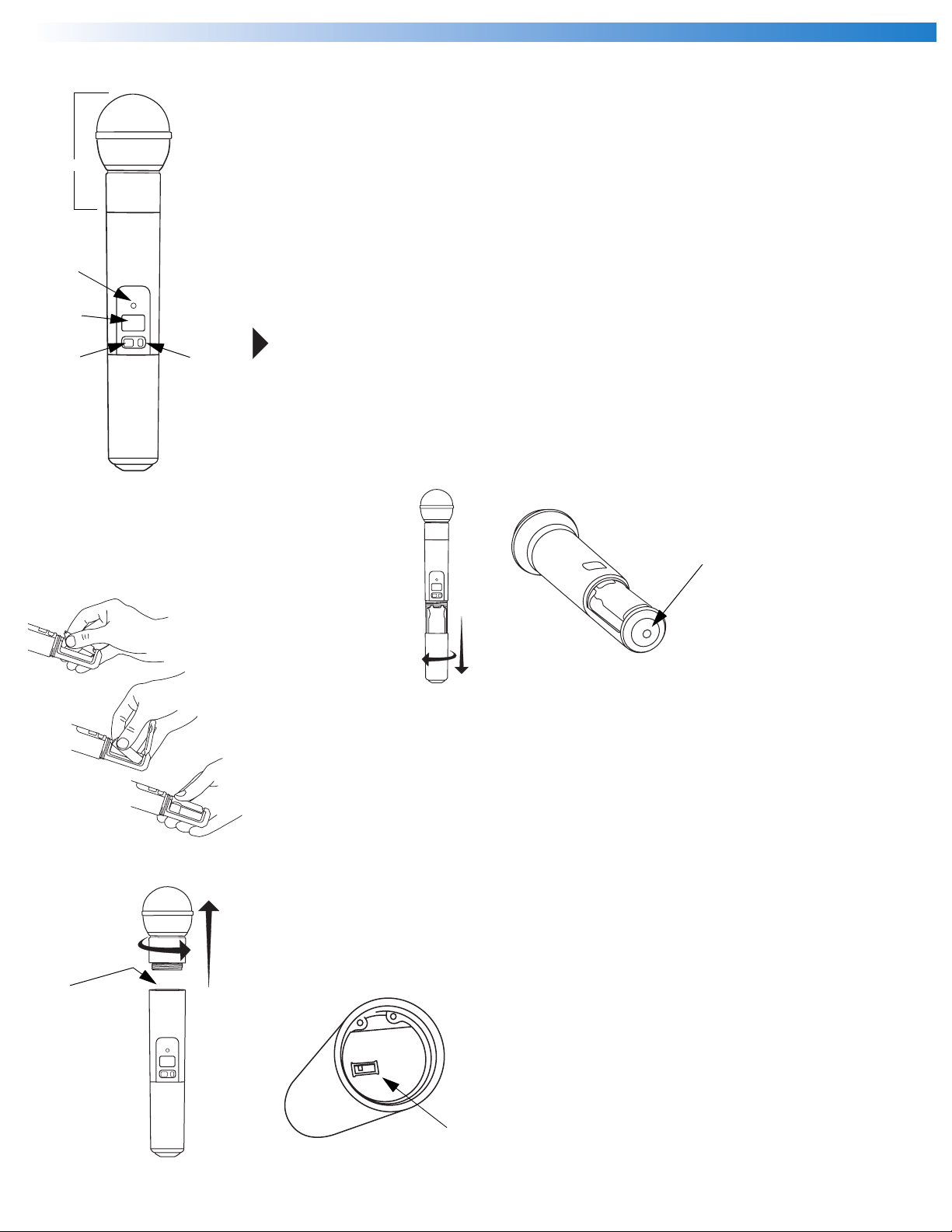
Features
Interchangeable microphone head (SM58 pictured)
Power / Infrared (IR) / Mute indicator
Green: ready
Amber: mute on
Flashing red: IR transmission in process
Glowing red: battery power low
LCD screen
See “SLX1 and SLX2 Transmitter Programming” on page 10.
On-off / mute switch
Press and hold to turn on or off. Press and release to mute or unmute.
To avoid accidentally muting the microphone during a performance, lock the front panel
while the microphone is in use. See “Lock or Unlock Transmitter Settings” on page 10.
Select switch
See “SLX1 and SLX2 Transmitter Programming” on page 10.
IR port
Receives infrared beam to synchronize frequencies. When using multiple systems, only one
transmitter IR port should be exposed at a time.
Changing Batteries
●
Expected life for an Alkaline battery is approximately 8 hours.
●
When the transmitter light glows red, the batteries should be changed immediately, as
shown on the left.
Adjusting Gain
●
Access the gain adjustment switch by unscrewing the head of the microphone.
●
Two gain settings are available on the SLX2. Choose a setting appropriate for vocal
volume and for the performing environment. Use the tip of a pen or a small screwdriver
to move the switch.
•
0dB:
For quiet to normal vocal performance.
•
–10dB:
SLX
For loud vocal performance.
S
IA
SLX
B
IO
D
U
A
-10dB
0dB
6
Page 7
SLX1 Bodypack
Transmitter
English
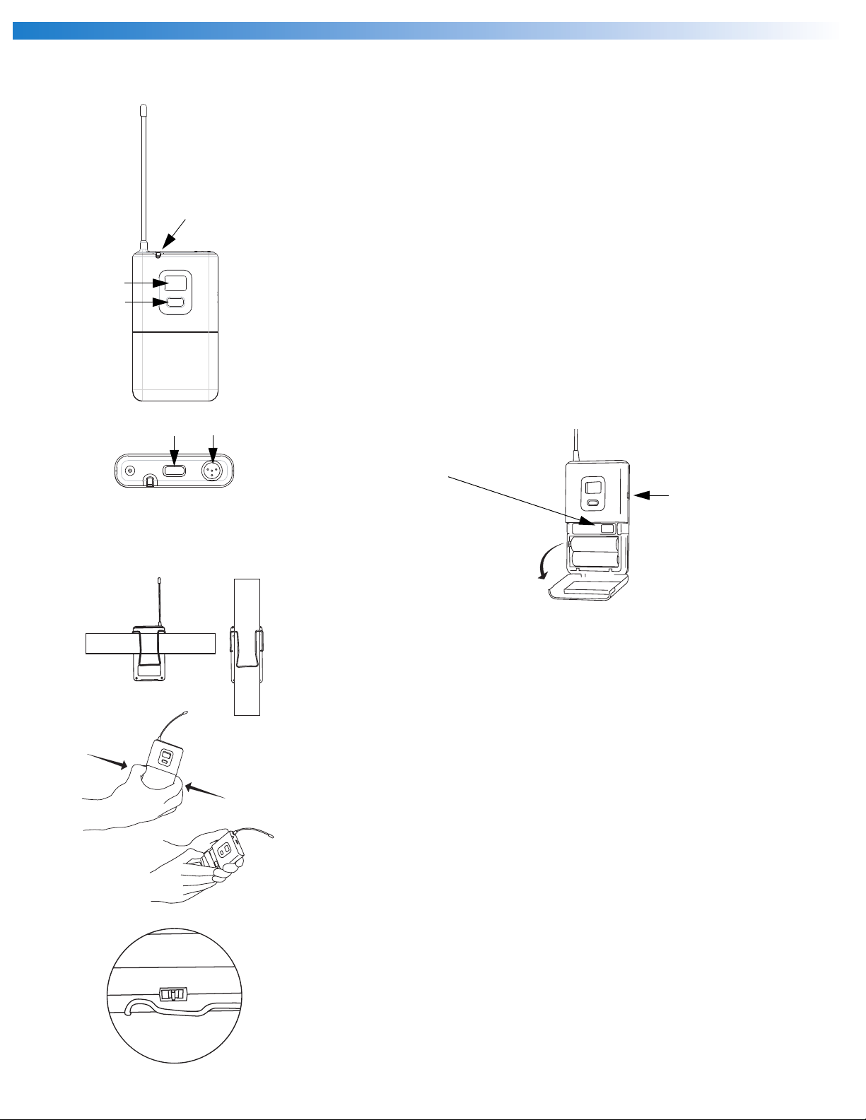
Features
Antenna
Power / Infrared (IR) / Mute indicator
Green: ready
Amber: mute on
Flashing red: IR transmission in process
Glowing red: battery power low
LCD screen
See “SLX1 and SLX2 Transmitter Programming” on page 10.
Select switch
See “SLX1 and SLX2 Transmitter Programming” on page 10.
On-off / mute switch
Press and hold to turn on or off. Press and release to mute or unmute.
4-Pin Microphone Input Jack
IR port
Receives infrared beam to synchronize frequencies. When using multiple systems, only one
transmitter IR port should be exposed at a time.
Gain adjustment switch (see below)
Wearing the Bodypack Transmitter
●
Clip the transmitter to a belt or slide a guitar strap through the transmitter clip as
shown.
●
For best results, slide the transmitter until the belt is pressed against the base of the
clip.
Changing Batteries
●
Expected life for an Alkaline battery is approximately 8 hours.
●
When the transmitter light glows red, the batteries should be changed immediately, as
shown on the left.
-10 0 m
Adjusting Gain
●
Three gain settings are available on the SLX1. Choose the appropriate setting for your
ic
instrument.
•
mic
: Microphone
•
0
: Guitar with passive pickups
•
-10
: Guitar with active pickups
7
Page 8

Shure SLX Wireless
Single System Setup
MASTER LIST
MANUAL
CHANNEL
SELECT
or
CHANNEL
DISPLAY
FREQUENCY
SELECT
MHz
EXIT
MASTER
LIST
< 15 cm (8 in
GROUP
888.888
GROUP
AUTO
SELECT
CHANNEL
SELECT
Follow these steps when using a single SLX system:
menu select
sync
ANTENNA
A
LOW BATT
1. Automatic Frequency Selection
Scans for an available channel and sets the receiver to that channel.
B
2. Automatic Transmitter Setup
Open the transmitter battery compartment to display the infrared (IR) port (see page 6 and
.)
page 7).
With the IR port exposed to the receiver, press sync.
Multiple System Setup
Follow these steps when using multiple SLX systems in a single installation:
1. Turn all receivers on and all transmitters off.
2. Set all receivers to the same frequency group (see “Group Selection” on page 9).
3. Perform Automatic Frequency Selection from the Single System Setup section
above.
4. Turn on the first transmitter.
5. Perform Automatic Transmitter Setup from the Single System Setup section above.
Repeat for each system.
Be sure that only one transmitter’s IR port is exposed when synchronizing a system.
8
Page 9

English
SLX Programming
MASTER LIST
CHANNEL
GROUP
888.888
GROUP
AUTO
SELECT
CHANNEL
SELECT
GROUP
888.888
GROUP
AUTO
SELECT
CHANNEL
SELECT
GROUP
888.888
GROUP
AUTO
SELECT
CHANNEL
SELECT
MANUAL
CHANNEL
SELECT
MANUAL
CHANNEL
SELECT
MANUAL
CHANNEL
SELECT
DISPLAY
FREQUENCY
SELECT
CHANNEL
DISPLAY
FREQUENCY
SELECT
CHANNEL
DISPLAY
FREQUENCY
SELECT
MASTER LIST
MASTER LIST
MHz
EXIT
MASTER
LIST
MHz
EXIT
MASTER
LIST
MHz
EXIT
MASTER
LIST
ANTENNA
A
LOW BATT
ANTENNA
A
LOW BATT
ANTENNA
A
LOW BATT
Any option displayed on screen will generally “time out” after five seconds.
SLX4 Receiver Programming
Group Selection
Allows manual selection of a frequency group. Pressing select increases the group number
B
by one. When the correct frequency is displayed, either wait five seconds for the screen to time
menu select sync
2x
out, or press sync. For best results when operating multiple systems, set all systems to a single
group; then set each system to a unique channel within that group.
For more information on frequency groups and channels, see “Frequency Band Selection” on
page 2.
Manual Channel Selection
Allows manual selection of a frequency channel. Pressing select increases the channel num-
B
ber by one.When the correct frequency is displayed, either wait five seconds for the screen to
menu select sync
3x
time out, or press sync.
Display Frequency
Displays the current frequency in Mhz for approximately 5 seconds. Press and hold to in-
B
crease display length.
menu select
4x
MASTER LIST
GROUP
GROUP
MANUAL
CHANNEL
SELECT
MANUAL
CHANNEL
SELECT
MANUAL
CHANNEL
SELECT
CHANNEL
DISPLAY
FREQUENCY
SELECT
CHANNEL
DISPLAY
FREQUENCY
SELECT
CHANNEL
DISPLAY
FREQUENCY
SELECT
MASTER
MASTER LIST
MASTER
MASTER LIST
MASTER
GROUP
888.888
GROUP
AUTO
SELECT
CHANNEL
SELECT
888.888
AUTO
SELECT
CHANNEL
SELECT
GROUP
888.888
GROUP
AUTO
SELECT
CHANNEL
SELECT
EXIT
LIST
EXIT
LIST
EXIT
LIST
MHz
MHz
MHz
ANTENNA
A
LOW BATT
ANTENNA
A
LOW BATT
ANTENNA
A
LOW BATT
Lock or Unlock Receiver Settings
Hold down the Select key and press Menu to lock or unlock the receiver. When locked, the
B
current receiver settings cannot be changed.
menuselect
+
Antenna Status
Indicates RF activity. Only one antenna is active at any one time.
B
Transmitter Battery Status
Indicates a low transmitter battery charge.
B
9
Page 10

SLX1 and SLX2 Transmitter Programming
Shure SLX Wireless
Incompatible
MASTER LIST
GROUP
8888
CHANNEL
Incompatible
MASTER LIST
GROUP
8888
Incompatible
MASTER LIST
GROUP
8888
Incompatible
MASTER LIST
GROUP
8888
Incompatible
MASTER LIST
GROUP
8888
CHANNEL
CHANNEL
CHANNEL
CHANNEL
Manually Select a Group and/or Channel
select
1. Press and hold the select button until the GROUP and CHANNEL displays begin to
alternate.
2. To change the group setting, release the select button while GROUP is displayed
While GROUP is flashing, pressing select increases the group setting by one.
3. To change the channel setting, release the select button while CHANNEL is displayed
. While CHANNEL is flashing, pressing select increases the channel setting by one.
Lock or Unlock Transmitter Settings
select
+
Press the mute/power and select buttons simultaneously to lock or unlock the transmitter settings. When locked, the current settings cannot be changed manually. Locking the transmitter
does not disable infrared synchronization.
Battery Status
Indicates charge remaining in transmitter batteries.
Master List Indicator
Indicates that a master list frequency is currently in use. No group or channel information is
displayed.
Note: the transmitter cannot be used to change master list settings.
.
GROUP
8888
MASTER LIST
MANUAL
CHANNEL
SELECT
MANUAL
CHANNEL
SELECT
MANUAL
CHANNEL
SELECT
CHANNEL
DISPLAY
FREQUENCY
SELECT
CHANNEL
DISPLAY
FREQUENCY
SELECT
CHANNEL
DISPLAY
FREQUENCY
SELECT
EXIT
MASTER
LIST
MASTER LIST
EXIT
MASTER
LIST
MASTER LIST
EXIT
MASTER
LIST
GROUP
888.888
GROUP
AUTO
SELECT
CHANNEL
SELECT
GROUP
888.888
GROUP
AUTO
SELECT
CHANNEL
SELECT
GROUP
888.888
GROUP
AUTO
SELECT
CHANNEL
SELECT
Incompatible
MASTER LIST
CHANNEL
MHz
MHz
MHz
ANTENNA
A
LOW BATT
ANTENNA
A
LOW BATT
ANTENNA
A
LOW BATT
Incompatible Frequency Warning
The incompatible warning indicates that the receiver and transmitter are transmitting on dif-
ferent frequency bands. Contact your Shure retailer for assistance.
The Master Frequency List
menu
Using the Master List
The “Master List” of frequencies should be accessed only by experienced users in situations
B
which call for precise frequency selection. The “Master List” is a comprehensive index of all avail-
+
able frequencies in 25 kHz increments.
To access the Master List, hold down the menu button while powering on the SLX receiver.
menu select
Select Frequencies in the Master List
While FREQUENCY SELECT is flashing, the select button scrolls down through all available
B
frequencies; the menu button scrolls up. Press and release to change the frequency in 25 kHz
select
menu
sync
increments; press and hold to scroll quickly.
When the correct frequency is displayed, either wait five seconds for the screen to time out,
or press sync.
Exit the Master List
menu select
2x
To exit the Master List and return to normal system operations, press menu, then select.
B
10
Page 11

English
Rack-Mounting an SLX
Receiver
The supplied mounting hardware allows an SLX receiver to be mounted in any standard 19”
audio equipment rack.
Hardware (Included) Assembly
Tools (Not Included)
Rack-Mounting SLX
Receivers
One Receiver Wiring Required Accessories
• All accessories
12–18 V
170 mA
BALANCED
LOW Z
POWER
SLX4
ANTENNA B
SHURE INCORPORATED
NILES, IL 60714
UNBALANCED
SLX4 RECEIVER
HIGH Z
N108
IC: 616A–SLX4
MIC OUT LINE OUT VOLUME ANTENNA A
supplied
Two Receivers
SLX4
SLX4
Two Receivers with UA220 Antenna Splitter/Combiner Kit
SLX4
SLX4
Three or Four Receivers
UHF ANTENNA / POWER DISTRIBUTION SYSTEM
SLX4
SLX4
UA844
POWER
SLX4
•1 x UA440
12–18 V
170 mA
BALANCED
LOW Z
POWER
ANTENNA B
12–18 V
170 mA
BALANCED
LOW Z
POWER
ANTENNA B
SHURE INCORPORATED
NILES, IL 60714
UNBALANCED
SLX4 RECEIVER
HIGH Z
IC: 616A–SLX4
MIC OUT LINE OUT VOLUME ANTENNA A
SHURE INCORPORATED
NILES, IL 60714
UNBALANCED
SLX4 RECEIVER
HIGH Z
IC: 616A–SLX4
MIC OUT LINE OUT VOLUME ANTENNA A
12–18 V
170 mA
BALANCED
N108
N108
LOW Z
POWER
ANTENNA B
12–18 V
170 mA
BALANCED
LOW Z
POWER
ANTENNA B
SHURE INCORPORATED
NILES, IL 60714
UNBALANCED
SLX4 RECEIVER
HIGH Z
N108
IC: 616A–SLX4
MIC OUT LINE OUT VOLUME ANTENNA A
SHURE INCORPORATED
NILES, IL 60714
UNBALANCED
SLX4 RECEIVER
HIGH Z
IC: 616A–SLX4
MIC OUT LINE OUT VOLUME ANTENNA A
N108
•1 x UA221
•1 x UA844
12–18 V
170 mA
BALANCED
LOW Z
POWER
ANTENNA B
12–18 V
170 mA
BALANCED
LOW Z
POWER
ANTENNA B
SHURE INCORPORATED
NILES, IL 60714
UNBALANCED
SLX4 RECEIVER
HIGH Z
IC: 616A–SLX4
MIC OUT LINE OUT VOLUME ANTENNA A
SHURE INCORPORATED
NILES, IL 60714
UNBALANCED
SLX4 RECEIVER
HIGH Z
IC: 616A–SLX4
MIC OUT LINE OUT VOLUME ANTENNA A
12–18 V
170 mA
BALANCED
N108
N108
LOW Z
POWER
ANTENNA B
SHURE INCORPORATED
NILES, IL 60714
UNBALANCED
SLX4 RECEIVER
HIGH Z
IC: 616A–SLX4
MIC OUT LINE OUT VOLUME ANTENNA A
N108
11
Page 12

Shure SLX Wireless
Receiver Volume
Control
The volume control dial should generally be left in
the clockwise position. Turning the dial counterclockwise decreases receiver output level.
Tips for Improving System Performance
●
Maintain a line of sight between transmitter and antenna
●
Avoid placing the receiver near metal surfaces or any digital equipment (CD players, computers, etc.)
●
Secure the AC adapter cable to the receiver using the cable retainer loop
●
If rack-mounting the receiver, front-mount the antennas as shown on page 8.
Troubleshooting
Issue Indicator Status Solution
No sound or faint
sound
Transmitter power light off
Receiver power light off
Receiver display indicates antenna
activity
If adjustments are necessary, use a small screw-
driver to turn the dial.
• Turn transmitter on (see
• Make sure the +/- indicators on battery match the transmitter terminals
• Insert a fresh battery
• Make sure AC adapter is securely plugged into electrical outlet and into
DC input connector on rear panel of receiver
• Make sure AC electrical outlet works and is supplying proper voltage
• Press mute switch on transmitter (see
• Turn up receiver volume control (see
• Increase transmitter gain switch setting (see
• Check cable connection between receiver and amplifier or mixer
pages 6 and 7
)
pages 6 and 7
page 5
)
pages 6 and 7
)
)
Distortion or
unwanted noise
bursts
Distortion level
increases gradually
Sound level different
from cabled guitar or
microphone, or when
using different guitars
Receiver display indicates no
antenna activity; transmitter and
receiver power lights glowing
Transmitter power light glowing red
Incompatible warning on
transmitter
Receiver display indicates antenna
activity
Transmitter power light glowing red
• Extend receiver antennas vertically
• Move receiver away from metal objects
• Check for line of sight between transmitter and receiver
• Move transmitter closer to receiver
• Check that receiver and transmitter are using the same frequency
• Replace transmitter batteries
•The
• Remove nearby sources of RF interference (CD players, computers,
• Change receiver and transmitter to a different frequency (see
• Reduce transmitter gain (see
• Replace transmitter battery
• If using multiple systems, increase the frequency spread between
• Replace transmitter batteries
• Adjust transmitter gain (see
incompatible
transmitting on different frequency bands. Contact your Shure retailer for
assistance.
digital effects, in-ear monitor systems, etc.)
systems (see page 9).
page 5
) as necessary
warning indicates that the receiver and transmitter are
page 9
pages 6 and 7
pages 6 and 7
)
) and receiver volume (see
)
12
Page 13

English
Specifications
System
Frequency Range and Transmitter Output Level
Band Range Transmitter output
H5
J3
L4
P4
R5
S6
JB
Q4
NOTE: This Radio apparatus may be capable of
operating on some frequencies not authorized in your
region. Please contact your national authority to obtain
information on authorized frequencies for wireless
microphone products in your region.
Operating Range Under Typical Conditions
100m (300 ft.)
Audio Frequency Response (+/–2 dB)
Minimum: 45 Hz
Maximum: 15 kHz
Total Harmonic Distortion (ref. +/–38 kHz deviation, 1
kHz tone)
0.5%, typical
Signal–to–Noise Ratio
>100 dB A–weighted
Operating Temperature Range
–18°C (0°F) to +57°C (+135°F)
Transmitter Audio Polarity
Positive pressure on microphone diaphragm (or positive
voltage applied to tip of WA302 phone plug) produces
positive voltage on pin 2 (with respect to pin 3 of low
impedance output) and the tip of the high impedance
1/4 inch output.
518–542 MHz 35 mW/15 dBm
572–596 MHz 35 mW/15 dBm
638–662 MHz 35 mW/15 dBm
702–726 MHz 35 mW/15 dBm
800–820 MHz 20 mW/13 dBm
838–865 MHz 10 mW/10 dBm
806–810 MHz 10 mW/10 dBm
740–752 MHz 10 mW/10 dBm
Note: actual range depends on RF signal absorption,
reflection, and interference
Note: battery characteristics may limit this range
SLX1 Bodypack Transmitter
Audio Input Level
+2 dBV maximum at 0 dB gain position
Dimensions
108 mm H x 64mm W x 19 mm D (4.25 x 2.50 x 0.75 in.)
Weight
81 grams (3 oz.) without batteries
Housing
Molded ABS case
Power
2 “AA” size alkaline or rechargeable batteries
Battery Life
>8 hours
SLX2 Handheld Transmitter
Audio Input Level
+2 dBV maximum at minimum gain position
Dimensions (including SM58 cartridge)
254 mm x 51 mm dia. (10 x 2 in.)
Weight
290 grams (10.2 oz.) without batteries
Housing
Molded ABS handle and battery cup
Power
2 “AA” size alkaline or rechargeable batteries
Battery Life
>8 hours
SLX4 Receiver
Dimensions
42 mm H x 197 mm W x 134 mm D (1.65 x 7.76 x
5.28 in.)
Weight
0.8165 kg (1 lb. 13 oz.)
Housing
Molded ABS
Sensitivity
–105 dBm for 12 dB SINAD, typical
Audio Output Level (ref. +/– 38 kHz deviation with 1 kHz
tone)
XLR connector (into 600 ohm load): +7 dBV (line), –
13 dBV (mic)
1/4 inch connector (into 3000 ohm load): –2 dBV
Sensitivity
–105 dBm for 12 dB SINAD, typical
Image Rejection
>70 dB, typical
Power
12–18 Vdc at 150 mA, supplied by external power
supply
13
Page 14

Shure SLX Wireless
Replacement
Parts and
Accessories
Optional Accessories Furnished Accessories
AC Adapter (120 VAC, 60 Hz) PS20
AC Adapter (230 VAC, 50/60 Hz, Europlug) PS20E
AC Adapter (230 VAC, 50/60 Hz, UK) PS20UK
AC Adapter (100 VAC, 50/60 Hz) PS20J
SM58 Head with Grille (SLX2/SM58) RPW112
SM86 Head with Grille (SLX2/SM86) RPW114
BETA 58 Head with Grille SLX2/BETA 58 RPW118
BETA 87A Head with Grille
(SLX2/BETA 87A)
BETA 87C Head with Grille
(SLX2/BETA 87C)
Matte Silver Grille (SLX2/SM58) RK143G
Matte Silver Grille (SLX2/SM86) RPM226
Matte Silver Grille (SLX2/BETA 58) RK265G
Matte Silver Grille (SLX2/BETA 87A) RK313
Matte Silver Grille (SLX2/BETA 87C) RK312
Belt Clip 44A8030
1/4-Wave Antenna (518–752 MHz) UA400B
1/4-Wave Antenna (748–865 MHz) UA400
RPW120
RPW122
Microphone Stand Adapter (SLX2) WA371
Zipper Bag (SLX1) 26A13
Zipper Bag (SLX2) 26A14
Short Rack Bar 53A8571
Long Rack Bar 53A8572
Link Bar 53A8443
Antenna extension cables (2) 95A9023
Optional Accessories
Carrying Case WA610
Black Grille (SLX2/BETA 58) RK323G
Black Grille (SLX2/BETA 87A) RK324G
Antenna Combiners and Accessories
Antennas and receivers must be from the same band.
The supplied 1/4 wave antennas can be used when mounted directly to the UA844. If antennas are remote
mounted, 1/2 wave antennas must be used.
Antennas and cables are for use with UA844, and cannot be used with stand-alone SLX receivers.
Passive Antenna/Splitter Combiner Kit
(recommended for 2 receivers)
UHF Antenna Power Distribution Amplifier
(recommended for 3 or more receivers)
U.S.A. UA844US
Europe UA844E
1/2 Wave Antenna Remote Mount Kit UA500
UA221
UK UA844UK
1/2 wave antennas (2)
H5 Band UA820H
J3 Band UA820D
L4 Band UA820L
P4, Q4 Bands UA820B
R5, S6, JB Bands UA820A
25’ Antenna Cable UA825
50’ Antenna Cable UA850
100’Antenna Cable UA100
14
Page 15

Microphone Specifications
WL183
+20
+10
dB
–10
-20
WL184
+20
+10
dB
–10
-20
WL185
+20
+10
dB
–10
-20
0
20 200001000 1000050 100
0
20 200001000 1000050 100
0
20 200001000 1000050 100
Hz
Hz
Hz
9876543298765432
9876543298765432
9876543298765432
180°
150°
120°
90°
60°
30°
150°
120°
90°
60°
30°
150°
120°
90°
60°
30°
–20 dB
–15 dB
–10 dB
–5 dB
180°
–20 dB
–15 dB
–10 dB
–5 dB
180°
–20 dB
–15 dB
–10 dB
–5 dB
150°
120°
90°
60°
30°
0
150°
120°
90°
60°
30°
0
150°
120°
90°
60°
30°
0
WL50
WL51
+20
+10
0
dB
–10
-20
20 200001000 1000050 100
+20
+10
0
dB
–10
-20
20 200001000 1000050 100
Mid Boost
Equalization Cap
High Boost
Equalization Cap
Hz
Hz
9876543298765432
On Axis
180° Off Axis
9876543298765432
180°
150°
120°
90°
60°
30°
180°
150°
120°
90°
60°
30°
–20 dB
–15 dB
–10 dB
–5 dB
150°
120°
60°
30°
0
250 Hz
500 Hz
1000 Hz
90°
–20 dB
–15 dB
–10 dB
–5 dB
150°
120°
90°
60°
30°
0
180°
150°
120°
90°
60°
30°
–20 dB
–15 dB
–10 dB
–5 dB
150°
120°
90°
60°
30°
0
2500 Hz
6300 Hz
10000 Hz
15
Page 16

Microphone Specifications
Shure SLX Wireless
WH20
+20
+10
0
dB
–10
-20
20 200001000 1000050 100
WH30
+20
+10
0
dB
–10
-20
20 200001000 1000050 100
BETA98H/C
+20
+10
0
dB
–10
-20
20 200001000 1000050 100
9876543298765432
Hz
1cm(.4in)
606 mm (2 ft)
9876543298765432
Hz
1 cm (3/8 in)
60.6 cm (2 ft)
9876543298765432
Hz
180°
150°
120°
90°
60°
30°
180°
150°
120°
90°
60°
30°
150°
120°
90°
60°
30°
–20 dB
–15 dB
–10 dB
–5 dB
–20 dB
–15 dB
–10 dB
–5 dB
150°
120°
60°
30°
0
125 Hz
250 Hz
500 Hz
180°
150°
120°
60°
30°
0
250 Hz
250 Hz
500 Hz
150°
120°
–20 dB
–15 dB
–10 dB
–5 dB
0
500 Hz
1000 Hz
4000 Hz
90°
90°
90°
90°
90°
60°
30°
180°
150°
120°
60°
30°
150°
120°
60°
30°
–20 dB
–15 dB
–10 dB
–5 dB
180°
–20 dB
–15 dB
–10 dB
–5 dB
150°
120°
90°
60°
30°
0
1000 Hz
5000 Hz
10000 Hz
150°
120°
90°
60°
30°
0
1000 Hz
5000 Hz
10000 Hz
SM58
SM86
+20
+10
0
dB
–10
-20
20 200001000 1000050 100
+20
+10
0
dB
–10
-20
20 200001000 1000050 100
Hz
Hz
9876543298765432
9876543298765432
180°
150°
120°
90°
60°
30°
150°
120°
90°
60°
30°
–20 dB
–15 dB
–10 dB
–5 dB
–20 dB
–15 dB
–10 dB
–5 dB
150°
120°
120°
90°
90°
60°
60°
30°
0
250 Hz
250 Hz
500 Hz
180°
150°
120°
120°
90°
90°
60°
60°
30°
0
250 Hz
500 Hz
1000 Hz
180°
150°
30°
150°
30°
–20 dB
–15 dB
–10 dB
–5 dB
–20 dB
–15 dB
–10 dB
–5 dB
150°
120°
90°
60°
30°
0
2000 Hz
4000 Hz
8000 Hz
180°
150°
120°
90°
60°
30°
0
2500 Hz
6400 Hz
10000 Hz
16
Page 17

Microphone Specifications
BETA58
+20
+10
0
dB
–10
-20
20 200001000 1000050 100
BETA87A
+20
+10
0
dB
–10
-20
20 200001000 1000050 100
BETA87C
+20
+10
0
dB
–10
-20
20 200001000 1000050 100
3 mm (1/8 in)
25 mm (1 in)
51 mm (2 in)
606 mm (2 ft)
9876543298765432
Hz
1 cm (3/8 in)
60.6 cm (2 ft)
9876543298765432
Hz
1 cm (3/8 in)
60.6 cm (2 ft)
9876543298765432
Hz
180°
150°
120°
90°
60°
30°
150°
120°
90°
60°
30°
150°
120°
90°
60°
30°
–20 dB
–15 dB
–10 dB
–5 dB
180°
–20 dB
–15 dB
–10 dB
–5 dB
180°
–20 dB
–15 dB
–10 dB
–5 dB
150°
120°
120°
90°
90°
60°
60°
30°
0
250 Hz
250 Hz
500 Hz
150°
120°
120°
90°
90°
60°
60°
30°
0
250 Hz
500 Hz
1000 Hz
150°
120°
120°
90°
90°
60°
60°
30°
0
250 Hz
500 Hz
1000 Hz
180°
150°
30°
150°
30°
150°
30°
–20 dB
–15 dB
–10 dB
–5 dB
–20 dB
–15 dB
–10 dB
–5 dB
–20 dB
–15 dB
–10 dB
–5 dB
150°
120°
90°
60°
30°
0
2500 Hz
6300 Hz
10000 Hz
180°
150°
120°
90°
60°
30°
0
2500 Hz
6300 Hz
10000 Hz
180°
150°
120°
90°
60°
30°
0
2500 Hz
5000 Hz
10000 Hz
17
Page 18

Shure SLX Wireless
Frequency Ranges
H5: 518,000–542,000 MHz
Group 1 Group 2 Group 3 Group 4 Group 5 Group 6
518.200 519.750 518.300 520.725 519.050 518.600
1
520.200 521.975 519.775 522.100 520.475 520.075
2
523.200 523.200 520.875 524.250 521.600 521.250
3
525.425 524.850 522.525 525.750 525.525 525.275
4
527.000 526.950 523.800 526.850 527.600 527.250
5
529.675 528.425 527.050 528.525 530.225 531.125
6
531.575 530.325 528.875 529.775 531.475 532.950
7
533.050 533.000 532.750 532.400 533.150 536.200
8
535.150 534.575 534.725 534.475 534.250 537.475
9
536.800 536.800 538.750 538.400 535.750 539.125
10
538.025 539.800 539.925 539.525 537.900 540.225
11
540.250 541.800 541.400 540.950 539.275 541.700
12
J3: 572,000–596,000 MHz
Group 1 Group 2 Group 3 Group 4 Group 5 Group 6
572.200 573.750 572.300 574.725 573.050 572.600
1
574.200 575.975 573.775 576.100 574.475 574.075
2
577.200 577.200 574.875 578.250 575.600 575.250
3
579.425 578.850 576.525 579.750 579.525 579.275
4
581.000 580.950 577.800 580.850 581.600 581.250
5
583.675 582.425 581.050 582.525 584.225 585.125
6
585.575 584.325 582.875 583.775 585.475 586.950
7
587.050 587.000 586.750 586.400 587.150 590.200
8
589.150 588.575 588.725 588.475 588.250 591.475
9
590.800 590.800 592.750 592.400 589.750 593.125
10
592.025 593.800 593.925 593.525 591.900 594.225
11
594.250 595.800 595.400 594.950 593.275 595.700
12
L4: 638,000–662,000 MHz
Group 1 Group 2 Group 3 Group 4 Group 5 Group 6
638.200 639.750 638.300 640.725 639.050 638.600
1
640.200 641.975 639.775 642.100 640.475 640.075
2
643.200 643.200 640.875 644.250 641.600 641.250
3
645.425 644.850 642.525 645.750 645.525 645.275
4
647.000 646.950 643.800 646.850 647.600 647.250
5
649.675 648.425 647.050 648.525 650.225 651.125
6
651.575 650.325 648.875 649.775 651.475 652.950
7
653.050 653.000 652.750 652.400 653.150 656.200
8
655.150 654.575 654.725 654.475 654.250 657.475
9
656.800 656.800 658.750 658.400 655.750 659.125
10
658.025 659.800 659.925 659.525 657.900 660.225
11
660.250 661.800 661.400 660.950 659.275 661.700
12
18
Page 19

Frequency Ranges
P4: 702,000–726,000
Group 1 Group 2 Group 3 Group 4 Group 5 Group 6 Group 7 Group 8
702.200 703.750 703.650 702.750 703.750 702.100 704.775 702.300
1
704.200 705.975 705.650 704.500 705.750 704.025 706.225 704.975
2
707.200 707.200 708.650 705.750 708.250 705.500 710.500 706.775
3
709.425 708.850 710.875 708.250 711.750 708.500 712.025 709.100
4
711.000 710.950 712.450 711.250 714.500 710.100 714.225 710.300
5
713.675 712.425 715.125 712.500 715.750 712.025 716.900 712.225
6
715.575 714.325 717.025 715.250 718.750 713.500 718.500 714.775
7
717.050 717.000 718.500 718.750 721.250 717.300 720.775 716.700
8
719.150 718.575 720.600 721.250 722.500 725.300 725.300 724.000
9
720.800 720.800 722.250 723.250 724.250 725.900
10
722.025 723.800 723.475
11
724.250 725.800 725.700
12
Group 9 Group 10 Group 11 Group 12 Group 13 Group 14 Group 15 Group 16
703.000 702.200 710.200 718.200 702.550 702.100 702.700 702.500
1
706.025 703.300 711.300 719.300 705.600 704.700 704.700 705.500
2
708.000 704.700 712.700 720.700 707.500 710.300 709.450 707.000
3
710.300 705.800 713.800 721.800 709.000 712.400 711.500 712.200
4
712.225 707.675 715.675 723.675 711.500 714.000 714.500 714.100
5
716.000 708.775 716.775 715.100 716.500 716.550 716.400
6
717.100 717.000 719.400 719.900 719.500
7
719.000 720.000 721.300 722.000 722.200
8
720.225 723.500 724.700
9
722.775 725.900 725.900
10
724.700
11
R5: 800,000–820,000, 800,100–819,000
Group 1 Group 2 Group 3 Group 4 Group 5 Group 6 Group 7
801.250 801.225 800.950 800.525 801.475 800.600 800.650
1
804.825 804.800 802.950 801.925 803.025 802.050 803.125
2
806.975 806.950 804.325 803.650 805.800 804.275 804.450
3
808.800 808.775 806.425 804.850 806.950 805.750 806.150
4
810.325 810.300 808.050 807.400 809.125 806.850 807.250
5
811.550 811.525 809.275 808.525 810.575 808.550 808.725
6
813.175 813.150 810.800 810.275 811.725 809.875 810.950
7
815.275 815.250 812.625 811.550 813.800 812.350 812.400
8
816.650 816.625 814.775 813.775 813.450 813.500
9
818.650 818.625 818.350
10
819.750 819.800 819.775
11
Group 8 Group 9 Group 10 Group 11 Group 12 Group 13 Group 14
806.000 806.025 801.400 800.900 801.200 803.850 806.150
1
807.100 807.425 808.300 802.100 803.800 807.000 811.650
2
808.500 808.525 816.400 806.200 805.900 809.700 814.400
3
809.600 810.400 809.300 807.000 811.050 816.500
4
811.475 811.500 814.100 809.200 813.900 817.450
5
812.575 812.900 816.100 811.700 816.500 819.300
6
813.975 814.000 817.200 817.600
7
8
819.600 819.500
19
Page 20

Shure SLX Wireless
Frequency Ranges
S6: 838,000–865,000
Group 1 Group 2 Group 3 Group 4 Group 5 Group 6 Group 7 Group 8
838.200 838.150 838.550 854.200 855.475 855.075 854.750 854.750
1
841.450 839.375 839.775 855.300 857.425 857.775 855.850 855.850
2
843.275 841.300 841.700 856.700 860.600 860.725 857.250 857.250
3
846.225 842.475 842.875 857.800 858.350 858.350
4
847.350 846.400 846.800 859.675 860.225 860.225
5
850.125 848.025 848.425 860.775 861.325 861.325
6
852.575 850.025 850.425
7
854.575 852.475 852.875
8
856.200 855.250 855.650
9
860.125 856.375 856.775
10
861.300 859.325 859.725
11
863.225 861.150 861.550
12
864.450 864.400 864.800
13
Group 9 Group 10 Group 11 Group 12 Group 13 Group 14 Group 15
854.425 863.200 838.200 838.900 838.100 838.700 838.400
1
855.525 864.500 839.900 842.600 841.100 842.800 840.600
2
857.400 841.000 845.900 842.700 844.800 842.100
3
858.500 842.375 847.500 847.000 846.300 844.700
4
859.900 844.400 848.600 849.200 847.400 846.600
5
861.000 846.100 850.100 850.400 849.200 848.100
6
7
8
9
10
11
12
13
847.350 852.100 852.500 851.300 850.700
849.400 853.300 854.100 851.850
851.800 855.100 855.300 853.700
853.200 857.210
858.650 KE ch's KE ch's S5 ch's
859.800 856.950 852.450 855.275
861.900 859.375 854.900 856.175
20
Page 21

Regulatory Information
SLX1 & SLX2 Transmitters: Certified to FCC Part 74 (FCC ID: "DD4SLX1" & "DD4SLX2"). Certified
by IC in Canada under RSS-123 and RSS-102 ("IC: 616A-SLX1" and "IC: 616A-SLX2"). This class B
digital apparatus complies with Canadian ICES-003. Meets the essential requirements of the European R&TTE Directive 99/5/EC (ETSI EN 300-422 Parts 1 & 2, EN 301 489 Parts 1 & 9) and are eligible
to carry the CE marking.
SLX4 Receiver: Authorized under Declaration of Conformity (DoC) provision of FCC Part 15. Certified under Industry Canada to RSS-123 ("IC: 616A-SLX4"). This class B digital apparatus complies
with Canadian ICES-003. Meets the essential requirements of the European R&TTE Directive 99/5/
EC (EN 301 489 Parts 1 & 2, EN 300 422 Parts 1 & 2) and is eligible to carry the CE marking.
Conforms to Australian EMC requirements and is eligible for C-Tick marking.
PS 20 Series Power Supplies: Conform to Safety Standard IEC 60065. PS20E and PS20UK are
eligible to bear CE marking.
European Countries and Frequencies
N108
21
 Loading...