

Page 1
Page 2

Shure SLX Wireless
Shure SLX Wireless
Smart, Hard-working
Wireless
Congratulations! Welcome to Shure SLX Wireless. Your new system is rugged, reliable, easy
to set up and operate, and produces outstanding audio clarity. Whether you’re a vocalist, guitarist, or instrumentalist, your SLX Wireless system will show you how easy wireless can be, and
how good wireless can sound.
This user guide and the Quick Setup guide included with your system will tell you all you need
to know to get your system working right away.
Welcome to the world of SLX: smart, hard-working wireless.
Frequency Band Selection
Most countries closely regulate the radio frequencies used in the transmission of wireless information. These regulations state which devices can use which frequencies, and help to limit
the amount of RF (radio frequency) interference in all wireless communications.
To be flexible enough to operate worldwide, SLX receivers are available in a number of models, each with a unique frequency range. Each frequency range, or band, spans up to 24 MHz of
the wireless broadcast spectrum. Available bands are:
H5: 518–542 MHz
J3: 572–596 MHz
L4: 638–662 MHz
P4: 702–726 MHz
R13: 794-806 MHz
To facilitate system setup and protect against RF interference, each system comes with multiple predefined frequency groups and channels.
When using a single SLX system, the operating frequency will generally not have to be
changed. In an installation with multiple receiver/transmitter systems, each system must operate
on a separate channel. The group and channel system provides an optimum frequency spread
when using multiple systems.
Within a single frequency band, up to 12 individual transmitter/receiver systems may be used
in a single installation. In regions where additional frequency bands are available, it is possible
to operate up to 20 systems simultaneously. Check with your local Shure retailer for information
on which bands are available in your area.
R5: 800–820 MHz
S6: 838–865 MHz
JB: 806–810 MHz
Q4: 740–752 MHz
What Do You Want to Do
Now?
Learn about your SLX4 Receiver
Power, lock/unlock, front and back panel features: See “SLX4 Receiver Features” on page 5
and “SLX4 Receiver Programming” on page 9.
Learn about your SLX2 Handheld Transmitter
Power, mute, gain, lock/unlock, other features: See “SLX2 Handheld Transmitter” on page 6
and “SLX1 and SLX2 Transmitter Programming” on page 10.
Learn about your SLX1 Bodypack Transmitter
Power, mute, gain, lock/unlock, other features: See “SLX1 Bodypack Transmitter” on page 7
and “SLX1 and SLX2 Transmitter Programming” on page 10.
Program your SLX Receiver and Transmitter
Frequency selection, LCD features, using the select and menu buttons: See “SLX Program-
ming” on page 9.
Learn how to use multiple systems in a single installation
See “Multiple System Setup” on page 8.
Troubleshoot your SLX system
See “Troubleshooting” on page 12.
2
Page 3

English
Table of Contents
System Components . . . . . . . . . . . . . . . . . . . . . . . . . . . . . . . . . . . . . . . . . . . . . 4
SLX4 Receiver Features . . . . . . . . . . . . . . . . . . . . . . . . . . . . . . . . . . . . . . . . . . . 5
SLX2 Handheld Transmitter. . . . . . . . . . . . . . . . . . . . . . . . . . . . . . . . . . . . . . . . 6
SLX1 Bodypack Transmitter . . . . . . . . . . . . . . . . . . . . . . . . . . . . . . . . . . . . . . . 7
Single System Setup . . . . . . . . . . . . . . . . . . . . . . . . . . . . . . . . . . . . . . . . . . . . . 8
Multiple System Setup . . . . . . . . . . . . . . . . . . . . . . . . . . . . . . . . . . . . . . . . . . . . 8
SLX Programming. . . . . . . . . . . . . . . . . . . . . . . . . . . . . . . . . . . . . . . . . . . . . . . . 9
SLX4 Receiver Programming . . . . . . . . . . . . . . . . . . . . . . . . . . . . . . . . . . . . . . 9
SLX1 and SLX2 Transmitter Programming. . . . . . . . . . . . . . . . . . . . . . . . . . . 10
The Master Frequency List . . . . . . . . . . . . . . . . . . . . . . . . . . . . . . . . . . . . . . . 10
Rack-Mounting SLX Receivers . . . . . . . . . . . . . . . . . . . . . . . . . . . . . . . . . . . . 11
Receiver Volume Control . . . . . . . . . . . . . . . . . . . . . . . . . . . . . . . . . . . . . . . . . 12
Tips for Improving System Performance . . . . . . . . . . . . . . . . . . . . . . . . . . . . 12
Troubleshooting . . . . . . . . . . . . . . . . . . . . . . . . . . . . . . . . . . . . . . . . . . . . . . . . 12
Specifications . . . . . . . . . . . . . . . . . . . . . . . . . . . . . . . . . . . . . . . . . . . . . . . . . . 13
Replacement Parts and Accessories . . . . . . . . . . . . . . . . . . . . . . . . . . . . . . . 14
Microphone Specification . . . . . . . . . . . . . . . . . . . . . . . . . . . . . . . . . . . . . . . 132
Frequency Ranges . . . . . . . . . . . . . . . . . . . . . . . . . . . . . . . . . . . . . . . . . . . . . 135
Regulatory Statements. . . . . . . . . . . . . . . . . . . . . . . . . . . . . . . . . . . . . . . . . . 139
Patent numbers 6,597,301, 5,794,125, and 5,692,057.
3
Page 4
Shure SLX Wireless
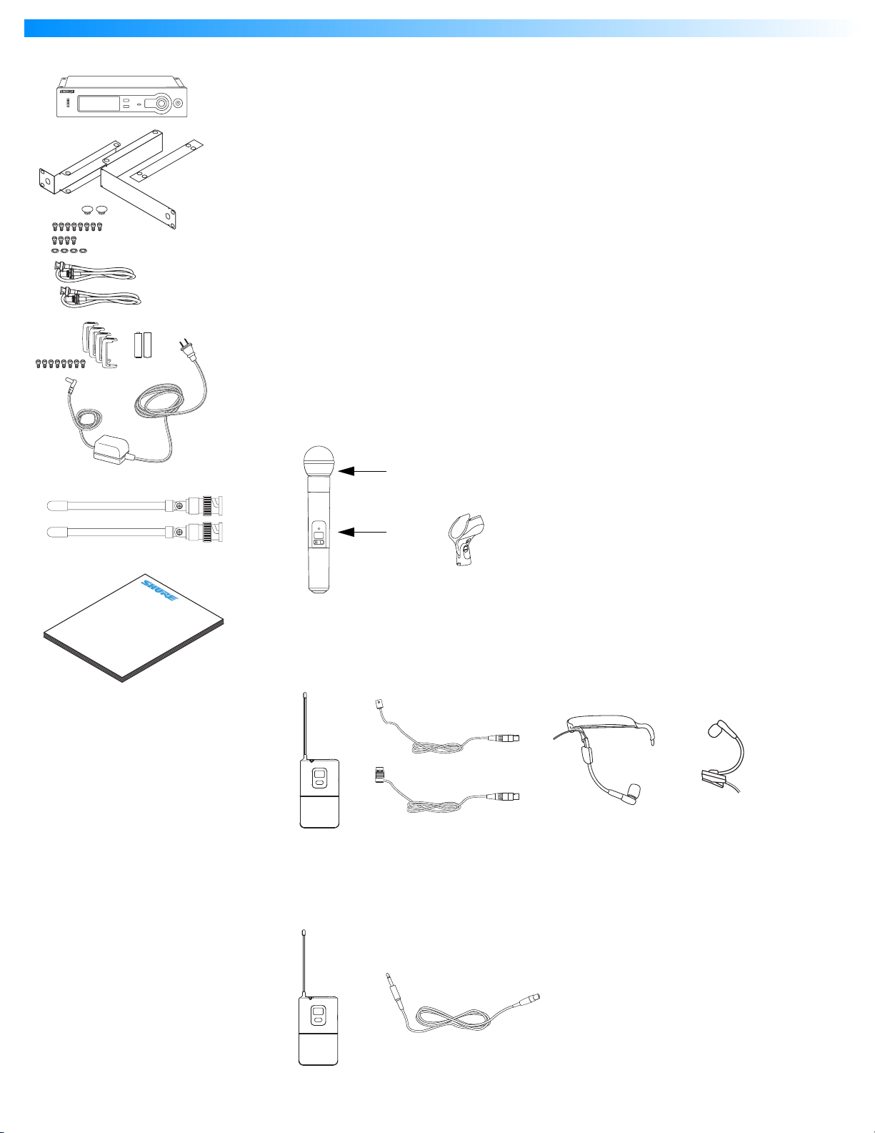
System Components
-
+
-
+
All systems include:
•
SLX4 receiver
•
Rack mount supplies
• Short rack ear
• Long rack ear
• Link bar to mount to similar receiver
• Extension cables and connectors for front-mounting antennas
• 8 rack ear screws
• 4 rack mount screws with washers
• 2 antenna hole plugs
•
Protective bumpers with 8 screws
•
2 AA batteries (4 in combo systems)
•
Power supply
•
2 1/4 Wave Antennas
•
User guide
Vocalist system includes:
•
Microphone Head (choice of SM58®, SM86, Beta 58A®, Beta 87A™, or Beta 87C™)
•
SLX2 handheld transmitter
•
Microphone clip
SLX
User Guide
®
Wireless Systems
SLX
mute select
Lavalier, Headworn, and Instrument systems include:
•
SLX1 bodypack transmitter
•
Microphone (choice of WL93 , WL184 or WL185 , WH30 , or Beta 98H/C™ )
Guitar system includes:
•
SLX1 bodypack transmitter
•
1/4” to mini 4-pin guitar cable
4
Page 5
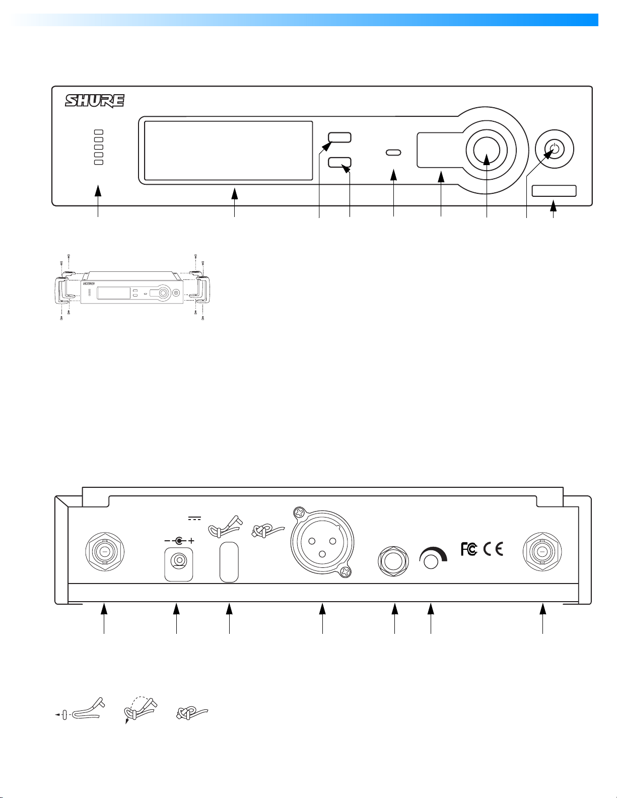
SLX4 Receiver Features
Front Panel
audio
English
SLX4
menu
sync
select ready
power
H5 518-542 Mhz
Back Panel
12–18 V
160 mA
Audio LED
Indicates strength of incoming audio
signal.
LCD panel
See “SLX Programming” on page 9.
Menu switch
Press to scroll through menu options.
See “SLX Programming” on page 9.
Select switch
Press to select the currently displayed
menu option. See “SLX Programming”
on page 9.
Sync Ready Indicator
Illuminates when frequencies of
receiver and transmitter are
synchronized. See “SLX Programming”
on page 9.
UNBALANCED
HIGH Z
Infrared (IR) port
Broadcasts IR signal to transmitter to
synchronize frequencies.
Sync Button
Press to initiate IR connection between
receiver and transmitter. See “SLX
Programming” on page 9.
On/Off switch
Tap to turn on, hold to turn off.
Frequency Band
Indicates the name and range of
receiver frequency band.
Adding protective bumpers
Recommended if receiver is not rack
mounted. Use supplied screws. For
rack-mounting instructions, See “Rack-
Mounting an SLX Receiver” on
page 11.
SHURE INCORPORATED
NILES, IL 60714
SLX4 RECEIVER
IC: 616A–SLX4
ANTENNA B
POWER
BALANCED
LOW Z
MIC OUT LINE OUT VOLUME ANTENNA A
Antenna jack B
AC adapter jack
Adapter cord tie-off
Follow steps shown to secure cord to
receiver body
1/4” output jack
Volume adjustment dial
Decreases receiver output level. See
“Receiver Volume Control” on page 12.
Antenna jack A
XLR output jack
5
Page 6
Shure SLX Wireless
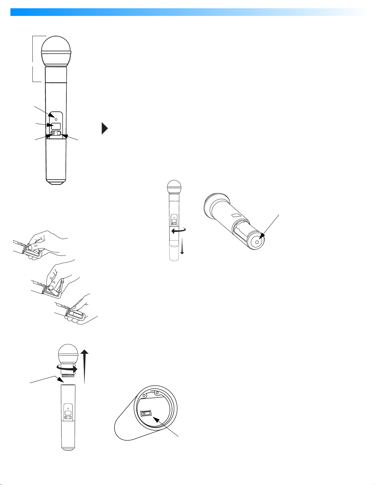
SLX2 Handheld Transmitter
SLX
mute select
Features
Interchangeable microphone head (SM58 pictured)
Power / Infrared (IR) / Mute indicator
Green: ready
Amber: mute on
Flashing red: IR transmission in process
Glowing red: battery power low
Pulsing red: battery dead (transmitter cannot be turned on until batteries are changed)
LCD screen
See “SLX1 and SLX2 Transmitter Programming” on page 10.
On-off / mute switch
Press and hold to turn on or off. Press and release to mute or unmute.
To avoid accidentally muting the microphone during a performance, lock the front panel
while the microphone is in use. See “Lock or Unlock Transmitter Settings” on page 10.
Select switch
See “SLX1 and SLX2 Transmitter Programming” on page 10.
IR port
Receives infrared beam to synchronize frequencies. When using multiple systems, only one
transmitter IR port should be exposed at a time.
Changing Batteries
•
Expected life for an Alkaline battery is approximately 8 hours.
•
When the transmitter light glows red, the batteries should be changed immediately, as
shown on the left.
Adjusting Gain
•
Access the gain adjustment switch by unscrewing the head of the microphone.
•
Two gain settings are available on the SLX2. Choose a setting appropriate for vocal
volume and for the performing environment. Use the tip of a pen or a small screwdriver
to move the switch.
•
0dB:
For quiet to normal vocal performance.
•
–10dB:
SLX
mute select
For loud vocal performance.
mute select
SLX
BIAS
AUDIO
0dB
-10dB
6
Page 7
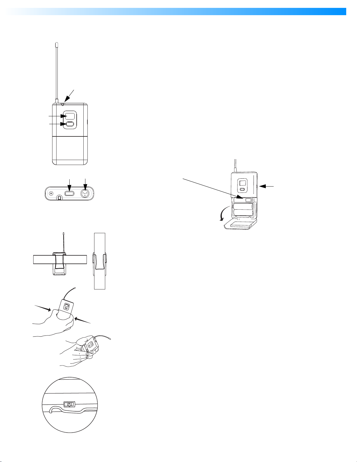
English
SLX1 Bodypack
Transmitter
Features
Antenna
Power / Infrared (IR) / Mute indicator
Green: ready
Amber: mute on
Flashing red: IR transmission in process
Glowing red: battery power low
Pulsing red: battery dead (transmitter cannot be turned off until batteries are changed)
LCD screen
See “SLX1 and SLX2 Transmitter Programming” on page 10.
Select switch
See “SLX1 and SLX2 Transmitter Programming” on page 10.
On-off / mute switch
Press and hold to turn on or off. Press and release to mute or unmute.
4-Pin Microphone Input Jack
IR port
Receives infrared beam to synchronize frequencies. When using multiple systems, only one
transmitter IR port should be exposed at a time.
Gain adjustment switch (see below)
-10
0 mic
Wearing the Bodypack Transmitter
•
Clip the transmitter to a belt or slide a guitar strap through the transmitter clip as
shown.
•
For best results, slide the transmitter until the belt is pressed against the base of the
clip.
Changing Batteries
•
Expected life for an Alkaline battery is approximately 8 hours.
•
When the transmitter light glows red, the batteries should be changed immediately, as
shown on the left.
Adjusting Gain
•
Three gain settings are available on the SLX1. Choose the appropriate setting for your
instrument.
•
mic
: Microphone (higher amplification)
•
0
: Guitar with passive pickups (medium amplification)
•
-10
: Guitar with active pickups (lower amplification)
•
If the receiver LED indicates the input volume is overloading the receiver, try switching
the gain to a lower setting.
7
Page 8
Shure SLX Wireless
Single System Setup
MASTER LIST
CHANNEL
GROUP
888.888
GROUP
AUTO
CHANNEL
SELECT
SELECT
MANUAL
CHANNEL
SELECT
or
FREQUENCY
< 15 cm (8 in.)
DISPLAY
SELECT
MHz
EXIT
MASTER
LIST
ANTENNA
A
LOW BATT
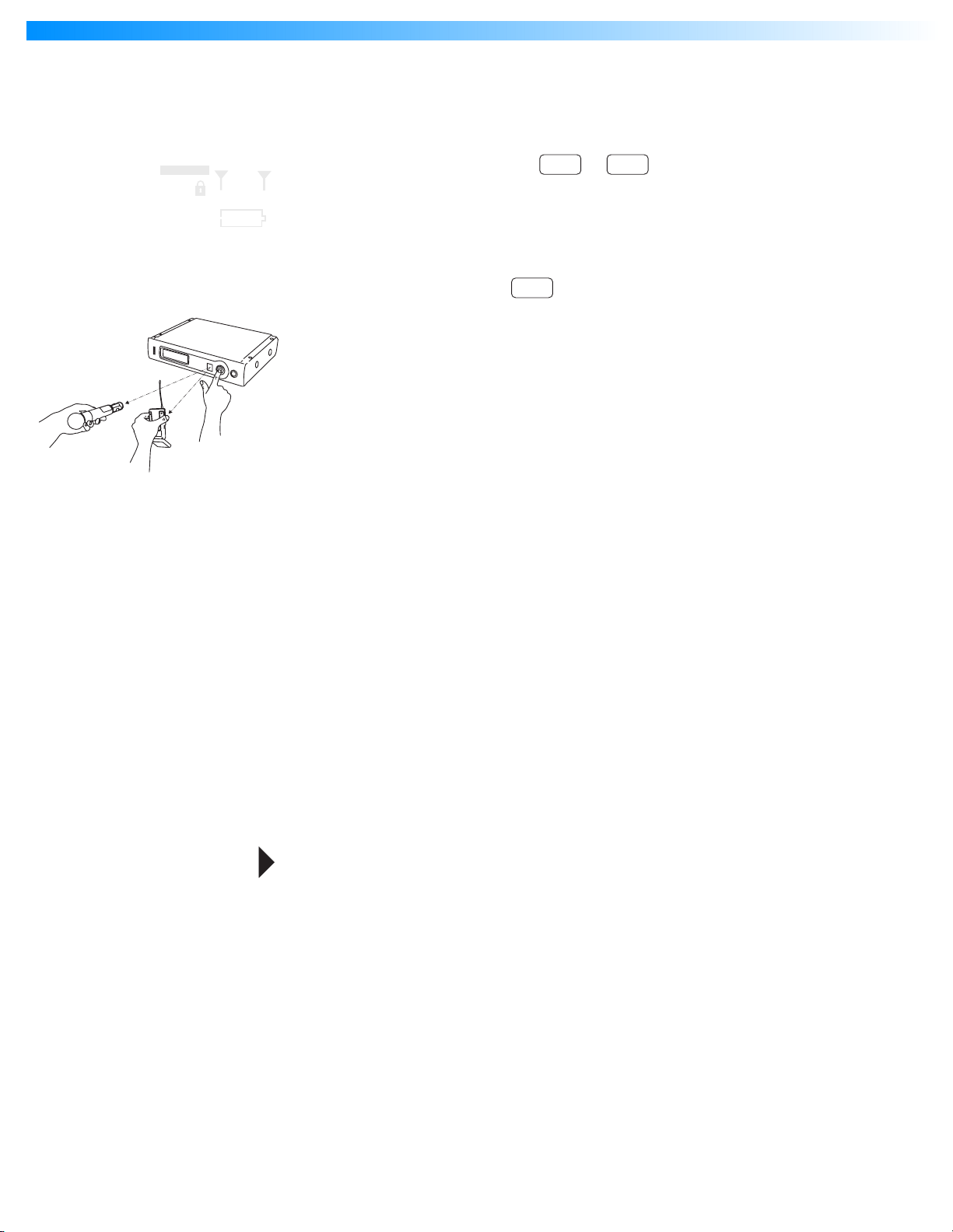
Note: transmitting devices such as cellular phones and two-way radios may interfere with
wireless audio transmissions. Keep your SLX transmitters and receivers away from these and
other potential sources of interference.
Follow these steps when using a single SLX system:
1. Automatic Frequency Selection
Scans for an available channel and sets the receiver to that channel.
B
2. Automatic Transmitter Setup
menu select
sync
Turn On the transmitter.
Open the transmitter battery compartment to display the infrared (IR) port
(see page 6 and page 7).
With the IR port exposed to the receiver, press sync.
Hold the sync button until the red light stops flashing on both receiver and transmitter.
When the receiver ready light glows, the system is ready for use.
Close the transmitter battery compartment.
Multiple System Setup
Follow these steps when using multiple SLX systems in a single installation:
1. Turn all receivers on and all transmitters off.
2. Set all receivers to the same frequency group (see “Group Selection” on page 9).
3. Perform Automatic Frequency Selection from the Single System Setup section
above.
4. Turn on the first transmitter.
5. Perform Automatic Transmitter Setup from the Single System Setup section above.
Repeat for each system.
Be sure that only one transmitter’s IR port is exposed when synchronizing a system.
8
Page 9
English
SLX Programming
MASTER LIST
GROUP
GROUP
MANUAL
CHANNEL
SELECT
MANUAL
CHANNEL
SELECT
MANUAL
CHANNEL
SELECT
CHANNEL
DISPLAY
FREQUENCY
SELECT
CHANNEL
DISPLAY
FREQUENCY
SELECT
CHANNEL
DISPLAY
FREQUENCY
SELECT
MASTER LIST
MASTER LIST
GROUP
888.888
GROUP
AUTO
SELECT
CHANNEL
SELECT
888.888
AUTO
SELECT
CHANNEL
SELECT
GROUP
888.888
GROUP
AUTO
SELECT
CHANNEL
SELECT
MHz
EXIT
MASTER
LIST
MHz
EXIT
MASTER
LIST
MHz
EXIT
MASTER
LIST
ANTENNA
A
LOW BATT
ANTENNA
A
LOW BATT
ANTENNA
A
LOW BATT
Any option displayed on screen will generally “time out” after five seconds.
SLX4 Receiver Programming
Group Selection
Allows manual selection of a frequency group. Pressing select increases the group number
B
by one. When the correct frequency is displayed, either wait five seconds for the screen to time
menu select sync
2x
out, or press sync. For best results when operating multiple systems, set all systems to a single
group; then set each system to a unique channel within that group.
For more information on frequency groups and channels, see “Frequency Band Selection” on
page 2.
Manual Channel Selection
Allows manual selection of a frequency channel. Pressing select increases the channel num-
B
ber by one.When the correct frequency is displayed, either wait five seconds for the screen to
menu select sync
3x
time out, or press sync.
Display Frequency
Displays the current frequency in MHz for approximately 5 seconds. Press and hold to in-
B
crease display length.
menu select
4x
MASTER LIST
MANUAL
CHANNEL
SELECT
MANUAL
CHANNEL
SELECT
MANUAL
CHANNEL
SELECT
MANUAL
CHANNEL
SELECT
CHANNEL
FREQUENCY
CHANNEL
FREQUENCY
CHANNEL
FREQUENCY
CHANNEL
DISPLAY
FREQUENCY
SELECT
DISPLAY
SELECT
MASTER LIST
DISPLAY
SELECT
MASTER LIST
DISPLAY
SELECT
MASTER LIST
MASTER
GROUP
888.888
GROUP
AUTO
SELECT
CHANNEL
SELECT
GROUP
888.888
GROUP
AUTO
SELECT
CHANNEL
SELECT
GROUP
888.888
GROUP
AUTO
SELECT
CHANNEL
SELECT
GROUP
FULL
GROUP
AUTO
SELECT
CHANNEL
SELECT
EXIT
MASTER
LIST
EXIT
MASTER
LIST
EXIT
MASTER
LIST
MHz
EXIT
LIST
MHz
MHz
MHz
ANTENNA
A
LOW BATT
ANTENNA
A
LOW BATT
ANTENNA
A
LOW BATT
ANTENNA
A
LOW BATT
Lock or Unlock Receiver Settings
Hold down the select key and press menu to lock or unlock the receiver. When locked, the
B
current receiver settings cannot be changed.
menuselect
+
Antenna Status
Indicates RF activity. Only one antenna is active at any one time.
B
Transmitter Battery Status
Indicates a low transmitter battery charge.
B
Full Group Warning
The FULL warning indicates that all available channels in the currently selected group are in
B
use. When this occurs, reprogram all systems to an alternate group.
Press either the menu or select button to exit the warning screen.
9
Page 10

Shure SLX Wireless
SLX1 and SLX2 Transmitter Programming
Incompatible
MASTER LIST
CHANNEL
GROUP
i8 i8
select select
MASTER LIST
GROUP
i8 i8
MASTER LIST
GROUP
i8 i8
Incompatible
MASTER LIST
GROUP
i8 i8
Incompatible
MASTER LIST
GROUP
i8 i8
Incompatible
CHANNEL
Incompatible
CHANNEL
CHANNEL
CHANNEL
Manually Select a Group and/or Channel
select
5
1. Press and hold the select button until the GROUP and CHANNEL displays begin to
alternate.
2. To change the group setting, release the select button while GROUP is displayed .
While GROUP is flashing, pressing select increases the group setting by one.
3. To change the channel setting, release the select button while CHANNEL is displayed
. While CHANNEL is flashing, pressing select increases the channel setting by one.
Lock or Unlock Transmitter Settings
select
+
Press the mute/ and select buttons simultaneously to lock or unlock the transmitter set-
tings. When locked, the current settings cannot be changed manually. Locking the transmitter
does not disable infrared synchronization.
Battery Status
Indicates charge remaining in transmitter batteries.
Master List Indicator
Indicates that a master list frequency is currently in use. No group or channel information is
displayed.
Note: the transmitter cannot be used to change master list settings.
GROUP
i8 i8
MASTER LIST
CHANNEL
GROUP
888.888
GROUP
AUTO
SELECT
CHANNEL
SELECT
GROUP
888.888
GROUP
AUTO
SELECT
CHANNEL
SELECT
GROUP
888.888
GROUP
AUTO
SELECT
CHANNEL
SELECT
MANUAL
CHANNEL
SELECT
MANUAL
CHANNEL
SELECT
MANUAL
CHANNEL
SELECT
DISPLAY
FREQUENCY
SELECT
CHANNEL
DISPLAY
FREQUENCY
SELECT
CHANNEL
DISPLAY
FREQUENCY
SELECT
MASTER
MASTER LIST
MASTER
MASTER LIST
MASTER
Incompatible
MASTER LIST
CHANNEL
MHz
EXIT
LIST
MHz
EXIT
LIST
MHz
EXIT
LIST
ANTENNA
A
LOW BATT
ANTENNA
A
LOW BATT
ANTENNA
A
LOW BATT
INCOMPATIBLE Frequency Warning
The INCOMPATIBLE warning indicates that the receiver and transmitter are set to incompatible fre-
quency bands. Contact your Shure retailer for assistance.
The Master Frequency List
menu
Using the Master List
The “Master List” of frequencies should be accessed only by experienced users in situations
B
which call for precise frequency selection. The “Master List” is a comprehensive index of all avail-
+
able frequencies in 25 kHz increments. (125 kHz increments in the JB band.)
To access the Master List, hold down the menu button while powering on the SLX receiver.
menu select
Select Frequencies in the Master List
While FREQUENCY SELECT is flashing, the select button scrolls down through all available
B
frequencies; the menu button scrolls up. Press and release to change the frequency in 25 kHz
select
menu
sync
increments; press and hold to scroll quickly.
When the correct frequency is displayed, either wait five seconds for the screen to time out,
or press sync.
Exit the Master List
menu select
2x
To exit the Master List and return to normal system operations, press menu, then select.
B
10
Page 11

English
Rack-Mounting an SLX
Receiver
The supplied mounting hardware allows an SLX receiver to be mounted in any standard 19”
audio equipment rack.
Hardware (Included) Assembly
Tools (Not Included)
Rack-Mounting SLX Receivers
One Receiver Wiring Required Accessories
SLX4
Two R eceivers
SLX4
SLX4
Two Receivers with UA221 Antenna Splitter/Combiner Kit
SLX4
SLX4
Three or Four Receivers
UHF ANTENNA / POWER DISTRIBUTION SYSTEM
SLX4
SLX4
UA844
POWER
SLX4
12–18 V
170 mA
BALANCED
LOW Z
POWER
ANTENNA B
SHURE INCORPORATED
NILES, IL 60714
UNBALANCED
SLX4 RECEIVER
HIGH Z
N108
IC: 616A–SLX4
MIC OUT LINE OUT VOLUME ANTENNA A
• All accessories
supplied
•1 x UA440
12–18 V
170 mA
BALANCED
LOW Z
POWER
ANTENNA B
12–18 V
170 mA
BALANCED
LOW Z
POWER
ANTENNA B
SHURE INCORPORATED
NILES, IL 60714
UNBALANCED
SLX4 RECEIVER
HIGH Z
IC: 616A–SLX4
MIC OUT LINE OUT VOLUME ANTENNA A
SHURE INCORPORATED
NILES, IL 60714
UNBALANCED
SLX4 RECEIVER
HIGH Z
IC: 616A–SLX4
MIC OUT LINE OUT VOLUME ANTENNA A
12–18 V
170 mA
BALANCED
N108
N108
LOW Z
POWER
ANTENNA B
12–18 V
170 mA
BALANCED
LOW Z
POWER
ANTENNA B
SHURE INCORPORATED
NILES, IL 60714
UNBALANCED
SLX4 RECEIVER
HIGH Z
N108
IC: 616A–SLX4
MIC OUT LINE OUT VOLUME ANTENNA A
SHURE INCORPORATED
NILES, IL 60714
UNBALANCED
SLX4 RECEIVER
HIGH Z
IC: 616A–SLX4
MIC OUT LINE OUT VOLUME ANTENNA A
N108
•1 x UA221
•1 x UA844
12–18 V
170 mA
BALANCED
LOW Z
POWER
ANTENNA B
12–18 V
170 mA
BALANCED
LOW Z
POWER
ANTENNA B
SHURE INCORPORATED
NILES, IL 60714
UNBALANCED
SLX4 RECEIVER
HIGH Z
IC: 616A–SLX4
MIC OUT LINE OUT VOLUME ANTENNA A
SHURE INCORPORATED
NILES, IL 60714
UNBALANCED
SLX4 RECEIVER
HIGH Z
IC: 616A–SLX4
MIC OUT LINE OUT VOLUME ANTENNA A
12–18 V
170 mA
BALANCED
N108
N108
LOW Z
POWER
ANTENNA B
SHURE INCORPORATED
NILES, IL 60714
UNBALANCED
SLX4 RECEIVER
HIGH Z
N108
IC: 616A–SLX4
MIC OUT LINE OUT VOLUME ANTENNA A
11
Page 12

Shure SLX Wireless
Receiver Volume
Control
The volume control dial should generally be left in the clockwise position. Turning the dial counter-clockwise
decreases receiver output level.
If adjustments are necessary, use a small screwdriver to turn the dial.
Tips for Improving System Performance
•
Maintain a line of sight between transmitter and antenna
•
Avoid placing the receiver near metal surfaces or any digital equipment (CD players, computers, etc.)
•
Secure the AC adapter cable to the receiver using the cable retainer loop
•
If rack-mounting the receiver, front-mount the antennas as shown on page 11.
Troubleshooting
Issue Indicator Status Solution
No sound or faint
sound
Transmitter power light off
Receiver LCD off
Receiver display indicates antenna
activity
• Turn transmitter on (see
• Make sure the +/- indicators on battery match the transmitter terminals
• Insert a fresh battery
• Make sure AC adapter is securely plugged into electrical outlet and into
DC input connector on rear panel of receiver
• Make sure AC electrical outlet works and is supplying proper voltage
• Press mute switch on transmitter (see
• Turn up receiver volume control (see
• Increase transmitter gain switch setting (see
• Check cable connection between receiver and amplifier or mixer
pages 6 and 7
)
pages 6 and 7
page 5
)
pages 6 and 7
)
)
Distortion or
unwanted noise
bursts
Distortion level
increases gradually
Sound level different
from cabled guitar or
microphone, or when
using different guitars
FULL warning
displays on receiver
Receiver display indicates no
antenna activity; transmitter and
receiver power lights glowing
Transmitter power light glowing or
flashing red
INCOMPATIBLE warning on
transmitter
Receiver display indicates antenna
activity
Transmitter power light glowing or
flashing red
• Extend receiver antennas vertically
• Move receiver away from metal objects
• Check for line of sight between transmitter and receiver
• Move transmitter closer to receiver
• Check that receiver and transmitter are using the same frequency
• Replace transmitter batteries
•The
• Remove nearby sources of RF interference (CD players, computers,
• Change receiver and transmitter to a different frequency (see
• Reduce transmitter gain (see
• Replace transmitter battery
• If using multiple systems, increase the frequency spread between
• Replace transmitter batteries
• Adjust transmitter gain (see
•The
INCOMPATIBLE
are set to incompatible frequency bands. Contact your Shure retailer for
assistance.
digital effects, in-ear monitor systems, etc.)
systems (see page 9).
page 5
) as necessary
FULL
selected group are in use. When this occurs, reprogram all systems to an
alternate group.
warning indicates that all available channels in the currently
warning indicates that the receiver and transmitter
page 9
pages 6 and 7
pages 6 and 7
)
) and receiver volume (see
)
Cannot turn
transmitter off
Transmitter light flashing red
• Replace transmitter batteries
12
Page 13

English
Specifications
System
Frequency Range and Transmitter Output Level
Band Range Transmitter output
H5
J3
L4
P4
R13
R5
S6
JB
Q4
NOTE: This Radio apparatus may be capable of
operating on some frequencies not authorized in your
region. Please contact your national authority to obtain
information on authorized frequencies for wireless
microphone products in your region.
Operating Range Under Typical Conditions
100m (300 ft.)
Audio Frequency Response (+/– 2 dB)
Minimum: 45 Hz
Maximum: 15 kHz
Total Harmonic Distortion (ref. +/– 38 kHz deviation,
1kHz tone)
0.5%, typical
Dynamic Range
>100 dB A-weighted
Operating Temperature Range
–18°C (0°F) to +57°C (+135°F)
Transmitter Audio Polarity
Positive pressure on microphone diaphragm (or positive
voltage applied to tip of WA302 phone plug) produces
positive voltage on pin 2 (with respect to pin 3 of low
impedance output) and the tip of the high impedance
1/4-inch output.
518–542 MHz 30 mW
572–596 MHz 30 mW
638–662 MHz 30 mW
702–726 MHz 30 mW
794-806 MHz 20 mW
800–820 MHz 20 mW
838–865 MHz 10 mW
806–810 MHz 10 mW
740–752 MHz 10 mW
Note: actual range depends on RF signal absorption,
reflection, and interference
(Overall system frequency depends on
microphone element.)
Note: battery characteristics may limit this range
SLX1 Bodypack Transmitter
Audio Input Level
-10 dBV maximum at mic gain position
+10 dBV maximum at 0 dB gain position
+20 dBV maximum at -10 dB gain position
Gain Adjustment Range
30dB
Input Impedance
1 MΩ
RF Transmitter Output
30 mW maximum (dependent on applicable country
regulations)
Dimensions
108 mm H x 64 mm W x 19 mm D (4.25 x 2.50 x
0.75 in.)
Weight
81 grams (3 oz.) without batteries
Housing
Molded ABS case
Power Requirements
2 “AA” size alkaline or rechargeable batteries
Battery Life
>8 hours (alkaline)
SLX2 Handheld Transmitter
Audio Input Level
+2 dBV maximum at -10dB position
-8 dBV maximum at 0dB position
Gain Adjustment Range
10dB
RF Transmitter Output
30 mW maximum (dependent on applicable country
regulations)
Dimensions (including SM58 cartridge)
254 mm x 51 mm dia. (10 x 2 in.)
Weight
290 grams (10.2 oz.) without batteries
Housing
Molded PC/ABS handle and battery cup
Power Requirements
2 “AA” size alkaline or rechargeable batteries
Battery Life
>8 hours (alkaline)
SLX4 Receiver
Dimensions
42 mm H x 197 mm W x 134 mm D (1.65 x 7.76 x
5.28 in.)
Weight
816 g (1 lb. 13 oz.)
Housing
Galvanized steel
Audio Output Level (ref. +/– 38 kHz deviation with 1 kHz
tone)
XLR connector (into 600 Ω load): –13 dBV
1/4 inch connector (into 3000 Ω load): –2 dBV
Output Impedance
XLR connector: 200 Ω
1/4 inch connector: 1kΩ
XLR output
Impedance balanced
Pin 1: Ground (cable shield)
Pin 2: Audio
Pin 3: No Audio
Sensitivity
–105 dBm for 12 dB SINAD, typical
Image Rejection
>70 dB, typical
Power Requirements
12–18 Vdc at 150 mA, supplied by external power
supply
13
Page 14

Shure SLX Wireless
Replacement
Parts and
Accessories
Replacement Parts (all systems)
Microphone Stand Adapter (SLX2) WA371
Zipper Bag (SLX1) 26A13
Zipper Bag (SLX2) 26A14
Short Rack Bar 53A8611
Long Rack Bar 53A8612
Link Bar 53B8443
Antenna extension cables (2) 95A9023
Protective Bumpers (SLX4 Receiver) (4) 90A8977
Replacement Parts (system-specific)
AC Adapter (120 VAC, 60 Hz) PS20
AC Adapter (220 VAC, 50 Hz) PS20AR
AC Adapter (230 VAC, 50/60 Hz, Europlug) PS20E
AC Adapter (230 VAC, 50/60 Hz, UK) PS20UK
AC Adapter (100 VAC, 50/60 Hz) PS20J
SM58 Head with Grille (SLX2/SM58) RPW112
SM86 Head with Grille (SLX2/SM86) RPW114
BETA 58 Head with Grille (SLX2/BETA 58) RPW118
BETA 87A Head with Grille
(SLX2/BETA 87A)
Beta 87C™ Head with Grille
(SLX2/Beta 87C™)
Matte Silver Grille (SLX2/SM58) RK143G
Matte Silver Grille (SLX2/SM86) RPM266
Matte Silver Grille (SLX2/BETA 58) RK265G
Matte Silver Grille (SLX2/BETA 87A) RK312
Matte Silver Grille (SLX2/Beta 87C™) RK312
Belt Clip 44A8030
1/4-Wave Antenna (518–752 MHz) UA400B
1/4-Wave Antenna (748–865 MHz) UA400
RPW120
RPW122
Optional Accessories
Carrying Case WA610
Black Grille (SLX2/BETA 58) RK323G
Black Grille (SLX2/BETA 87A) RK324G
Antenna Combiners and Accessories
Antennas and receivers must be from the same
band.
The supplied 1/4 wave antennas can be used when
mounted directly to the UA844. If antennas are remote
mounted, 1/2 wave antennas must be used.
Antennas and cables are for use with UA844, and
cannot be used with stand-alone SLX receivers.
Passive Antenna/Splitter Combiner Kit
(recommended for 2 receivers)
UHF Antenna Power Distribution Amplifier
(recommended for 3 or more receivers)
U.S.A. UA844US
Europe UA844E
1/2 Wave Antenna Remote Mount Kit UA500
1/2 wave antenna
H5 Band UA820H
J3 Band UA820F
L4 Band UA820L
P4, Q4 Bands UA820B
R13, R5, S6, JB Bands UA820A
25’ Antenna Cable UA825
50’ Antenna Cable UA850
100’Antenna Cable UA100
UA221
UK UA844UK
14
Page 15

Shure SLX Wireless
Microphone Specifications
WL183
+20
+10
dB
–10
-20
WL184
+20
+10
dB
–10
-20
WL185
+20
+10
0
dB
–10
-20
0
20 200001000 1000050 100
0
20 200001000 1000050 100
20 200001000 1000050 100
Hz
Hz
Hz
9876543298765432
9876543298765432
9876543298765432
180°
150°
120°
90°
60°
30°
150°
120°
90°
60°
30°
150°
120°
90°
60°
30°
–20 dB
–15 dB
–10 dB
–5 dB
180°
–20 dB
–15 dB
–10 dB
–5 dB
180°
–20 dB
–15 dB
–10 dB
–5 dB
150°
120°
90°
60°
30°
0
150°
120°
90°
60°
30°
0
150°
120°
90°
60°
30°
0
WL50
dB
WL51
+20
+10
0
–10
-20
20 200001000 1000050 100
+20
+10
0
dB
–10
-20
20 200001000 1000050 100
Mid Boost
Equalization Cap
High Boost
Equalization Cap
Hz
Hz
9876543298765432
On Axis
180° Off Axis
9876543298765432
180°
150°
120°
90°
60°
30°
180°
150°
120°
90°
60°
30°
–20 dB
–15 dB
–10 dB
–5 dB
150°
120°
60°
30°
0
250 Hz
500 Hz
1000 Hz
90°
–20 dB
–15 dB
–10 dB
–5 dB
150°
120°
90°
60°
30°
0
180°
150°
120°
90°
60°
30°
–20 dB
–15 dB
–10 dB
–5 dB
150°
120°
90°
60°
30°
0
2500 Hz
6300 Hz
10000 Hz
132
Page 16

Microphone Specifications
Microphone Specifications
WH20
+20
+10
0
dB
–10
-20
20 200001000 1000050 100
WH30
+20
+10
0
dB
–10
-20
20 200001000 1000050 100
BETA98H/C
+20
+10
0
dB
–10
-20
20 200001000 1000050 100
9876543298765432
Hz
1cm(.4in)
606 mm (2 ft)
9876543298765432
Hz
1 cm (3/8 in)
60.6 cm (2 ft)
9876543298765432
Hz
180°
150°
120°
90°
60°
30°
180°
150°
120°
90°
60°
30°
150°
120°
90°
60°
30°
–20 dB
–15 dB
–10 dB
–5 dB
180°
–20 dB
–15 dB
–10 dB
–5 dB
150°
120°
60°
30°
0
125 Hz
250 Hz
500 Hz
150°
120°
60°
30°
0
125 Hz
250 Hz
500 Hz
150°
120°
–20 dB
–15 dB
–10 dB
–5 dB
0
500 Hz
1000 Hz
4000 Hz
90°
90°
90°
90°
90°
60°
30°
180°
150°
120°
60°
30°
150°
120°
60°
30°
–20 dB
–15 dB
–10 dB
–5 dB
–20 dB
–15 dB
–10 dB
–5 dB
150°
120°
90°
60°
30°
0
1000 Hz
5000 Hz
10000 Hz
180°
150°
120°
90°
60°
30°
0
1000 Hz
5000 Hz
10000 Hz
SM58
dB
SM86
dB
+20
+10
0
–10
-20
20 200001000 1000050 100
+20
+10
0
–10
-20
20 200001000 1000050 100
Hz
Hz
9876543298765432
9876543298765432
180°
150°
120°
90°
60°
30°
150°
120°
90°
60°
30°
–20 dB
–15 dB
–10 dB
–5 dB
180°
–20 dB
–15 dB
–10 dB
–5 dB
150°
120°
120°
90°
90°
60°
60°
30°
0
125 Hz
500 Hz
1000 Hz
150°
120°
120°
90°
90°
60°
60°
30°
0
250 Hz
500 Hz
1000 Hz
180°
150°
30°
150°
30°
–20 dB
–15 dB
–10 dB
–5 dB
180°
–20 dB
–15 dB
–10 dB
–5 dB
150°
120°
90°
60°
30°
0
2000 Hz
4000 Hz
8000 Hz
150°
120°
90°
60°
30°
0
2500 Hz
6400 Hz
10000 Hz
133
Page 17

Shure SLX Wireless
Microphone Specifications
BETA58
+20
+10
0
dB
–10
-20
20 200001000 1000050 100
BETA87A
+20
+10
0
dB
–10
-20
20 200001000 1000050 100
BETA87C
+20
+10
0
dB
–10
-20
20 200001000 1000050 100
3 mm (1/8 in)
25 mm (1 in)
51 mm (2 in)
606 mm (2 ft)
9876543298765432
Hz
1 cm (3/8 in)
60.6 cm (2 ft)
9876543298765432
Hz
1 cm (3/8 in)
60.6 cm (2 ft)
9876543298765432
Hz
180°
150°
120°
90°
60°
30°
150°
120°
90°
60°
30°
150°
120°
90°
60°
30°
–20 dB
–15 dB
–10 dB
–5 dB
180°
–20 dB
–15 dB
–10 dB
–5 dB
180°
–20 dB
–15 dB
–10 dB
–5 dB
150°
120°
120°
90°
90°
60°
60°
30°
0
250 Hz
500 Hz
1000 Hz
150°
120°
120°
90°
90°
60°
60°
30°
0
250 Hz
500 Hz
1000 Hz
150°
120°
120°
90°
90°
60°
60°
30°
0
250 Hz
500 Hz
1000 Hz
180°
150°
30°
150°
30°
150°
30°
–20 dB
–15 dB
–10 dB
–5 dB
–20 dB
–15 dB
–10 dB
–5 dB
–20 dB
–15 dB
–10 dB
–5 dB
150°
120°
90°
60°
30°
0
2500 Hz
6300 Hz
10000 Hz
180°
150°
120°
90°
60°
30°
0
2500 Hz
6300 Hz
10000 Hz
180°
150°
120°
90°
60°
30°
0
2500 Hz
5000 Hz
10000 Hz
134
Page 18

English
Frequency
Ranges
H5: 518.000–542.000 MHz
Group 1 Group 2 Group 3 Group 4 Group 5 Group 6
518.400 519.250 518.200 519.775 519.100 518.425
1
521.500 520.500 519.675 522.500 521.225 520.400
2
523.575 522.225 520.800 524.200 522.550 523.425
3
525.050 524.725 522.450 525.600 524.575 525.475
4
527.425 526.350 523.750 526.700 526.900 527.775
5
529.200 527.550 526.200 528.250 530.500 531.675
6
532.450 530.800 528.325 529.500 531.750 533.800
7
533.650 532.575 532.225 533.100 533.300 536.250
8
535.275 534.950 534.525 535.425 534.400 537.550
9
537.775 536.425 536.575 537.450 535.800 539.200
10
539.500 538.500 539.600 538.775 537.500 540.325
11
540.750 541.600 541.575 540.900 540.225 541.800
12
Full Range even distribution for
each TV-CH
Full Range even distribution for
each TV-CH
Full Range - max.
# of frequencies
for CH- 22
Full Range - max.
# of frequencies
for CH- 23
Full Range - max.
# of frequencies
for CH- 24
Full Range - max.
# of frequencies
for CH- 25
J3: 572.000–596.000 MHz
Group 1 Group 2 Group 3 Group 4 Group 5 Group 6
572.400 573.250 572.200 573.775 573.100 572.425
1
575.500 574.500 573.675 576.500 575.225 574.400
2
577.575 576.225 574.800 578.200 576.550 577.425
3
579.050 578.725 576.450 579.600 578.575 579.475
4
581.425 580.350 577.750 580.700 580.900 581.775
5
583.200 581.550 580.200 582.250 584.500 585.675
6
586.450 584.800 582.325 583.500 585.750 587.800
7
587.650 586.575 586.225 587.100 587.300 590.250
8
589.275 588.950 588.525 589.425 588.400 591.550
9
591.775 590.425 590.575 591.450 589.800 593.200
10
593.500 592.500 593.600 592.775 591.500 594.325
11
594.750 595.600 595.575 594.900 594.225 595.800
12
Full Range even distribution for
each TV-CH
Full Range even distribution for
each TV-CH
Full Range - max.
# of frequencies
for CH- 31
Full Range - max.
# of frequencies
for CH- 32
Full Range - max.
# of frequencies
for CH- 33
Full Range - max.
# of frequencies
for CH- 34
L4: 638.000–662.000 MHz
Group 1 Group 2 Group 3 Group 4 Group 5 Group 6
638.400 639.250 638.200 639.775 639.100 638.425
1
641.500 640.500 639.675 642.500 641.225 640.400
2
643.575 642.225 640.800 644.200 642.550 643.425
3
645.050 644.725 642.450 645.600 644.575 645.475
4
647.425 646.350 643.750 646.700 646.900 647.775
5
649.200 647.550 646.200 648.250 650.500 651.675
6
652.450 650.800 648.325 649.500 651.750 653.800
7
653.650 652.575 652.225 653.100 653.300 656.250
8
655.275 654.950 654.525 655.425 654.400 657.550
9
657.775 656.425 656.575 657.450 655.800 659.200
10
659.500 658.500 659.600 658.775 657.500 660.325
11
660.750 661.600 661.575 660.900 660.225 661.800
12
Full Range even distribution for
each TV-CH
Full Range even distribution
for each TV-CH
Full Range - max.
# of frequencies
for CH- 42
Full Range - max.
# of frequencies
for CH- 43
Full Range - max.
# of frequencies
for CH- 44
Full Range - max.
# of frequencies
for CH- 45
135
Page 19

Shure SLX Wireless
Frequency
Ranges
P4: 702.000–726.000 MHz
Group 1 Group 2 Group 3 Group 4 Group 5 Group 6 Group 7 Group 8
702.200 703.750 703.650 702.750 703.750 702.100 704.775 702.300
1
704.200 705.975 705.650 704.500 705.750 704.025 706.225 704.975
2
707.200 707.200 708.650 705.750 708.250 705.500 710.500 706.775
3
709.425 708.850 710.875 708.250 711.750 708.500 712.025 709.100
4
711.000 710.950 712.450 711.250 714.500 710.100 714.225 710.300
5
713.675 712.425 715.125 712.500 715.750 712.025 716.900 712.225
6
715.575 714.325 717.025 715.250 718.750 713.500 718.500 714.775
7
717.050 717.000 718.500 718.750 721.250 717.300 720.775 716.700
8
719.150 718.575 720.600 721.250 722.500 725.300 725.300 724.000
9
720.800 720.800 722.250 723.250 724.250 725.900
10
722.025 723.800 723.475
11
724.250 725.800 725.700
12
Full Range max. # of
compatible
frequencies
Group 9 Group 10 Group 11 Group 12 Group 13 Group 14 Group 15 Group 16
703.000 702.200 710.200 718.200 702.550 702.100 702.700 702.500
1
706.025 703.300 711.300 719.300 705.600 704.700 704.700 705.500
2
708.000 704.700 712.700 720.700 707.500 710.300 709.450 707.000
3
710.300 705.800 713.800 721.800 709.000 712.400 711.500 712.200
4
712.225 707.675 715.675 723.675 711.500 714.000 714.500 714.100
5
716.000 708.775 716.775 715.100 716.500 716.550 716.400
6
717.100 717.000 719.400 719.900 719.500
7
719.000 720.000 721.300 722.000 722.200
8
720.225 723.500 724.700
9
722.775 725.900 725.900
10
724.700
11
France
preferred:
User Group C
Full Range max. # of
compatible
frequencies
Optimized TV
channels: TV
ch. 50 702710 MHz
Full Range max. # of
compatible
frequencies
Optimized TV
channels: TV
ch. 51 710718 MHz
France
preferred:
User Group A
Optimized TV
channels: TV
ch. 52 718724 MHz
France
preferred:
User Group A
Compatible
setup for use
with
PSM400-P3
(P4 > P3)
France
preferred:
User Group B
Compatible
setup for use
with
PSM400-P3
(P4 = P3)
France
preferred:
User Group B
Compatible
setup for use
with
PSM400-HF
(P4 > HF)
France
preferred:
User Group C)
Compatible
setup for use
with
PSM400-HF
(P4 = HF)
Frequency
Ranges
R5: 800.100–819.900 MHz
Group 1 Group2 Group 3 Group 4 Group 5 Group 6 Group 7
801.250 801.225 800.950 800.525 801.475 800.600 800.650
1
804.825 804.800 802.950 801.925 803.025 802.050 803.125
2
806.975 806.950 804.325 803.650 805.800 804.275 804.450
3
808.800 808.775 806.425 804.850 806.950 805.750 806.150
4
810.325 810.300 808.050 807.400 809.125 806.850 807.250
5
811.550 811.525 809.275 808.525 810.575 808.550 808.725
6
813.175 813.150 810.800 810.275 811.725 809.875 810.950
7
815.275 815.250 812.625 811.550 813.800 812.350 812.400
8
816.650 816.625 814.775 813.775 813.450 813.500
9
818.650 818.625 818.350
10
819.750 819.800 819.775
11
Full Range max. # of comp.
Frequencies &
FIN / NOR /
DEN
Full Range max. # of comp.
Frequencies &
FIN / NOR /
DEN
Full Range max. # of comp.
Frequencies &
FIN / NOR /
DEN
Germany
preferred: User
Group 4 800814 MHz
Group 8 Group 9 Group 10 Group 11 Group 12 Group 13 Group 14
806.000 806.025 801.400 800.900 801.200 803.850 806.150
1
807.100 807.425 808.300 802.100 803.800 807.000 811.650
2
808.500 808.525 816.400 806.200 805.900 809.700 814.400
3
809.600 810.400 809.300 807.000 811.050 816.500
4
811.475 811.500 814.100 809.200 813.900 817.450
5
812.575 812.900 816.100 811.700 816.500 819.300
6
813.975 814.000 817.200 817.600
7
819.600 819.500
8
Netherlands
preferred: TV
ch. 63 806814 MHz
Netherlands
preferred: TV
ch. 63 806814 MHz
Compatible
setup for use
with
EUT-TL-TV
(R5 > TL-TV)
Compatible
setup for use
with PSM400MN (R5 > MN)
Germany
preferred: User
Group 4 800814 MHz
Compatible
setup for use
with PSM400MN (R5 = MN)
Sweden
preferred:
800-814 MHz
Compatible
setup for use
with PSM200R8 (R5 > R8)
Sweden
preferred:
800-814 MHz
Compatible
setup for use
with PSM200R8 (R5 = R8)
136
Page 20

English
Frequency
Ranges
S6: 838.000–865.000 MHz
Group 1 Group 2 Group 3 Group 4 Group 5 Group 6 Group 7 Group 8
838.200 838.150 838.550 854.200 855.475 855.075 854.750 854.750
1
841.450 839.375 839.775 855.300 857.425 857.775 855.850 855.850
2
843.275 841.300 841.700 856.700 860.600 860.725 857.250 857.250
3
846.225 842.475 842.875 857.800 858.350 858.350
4
847.350 846.400 846.800 859.675 860.225 860.225
5
850.125 848.025 848.425 860.775 861.325 861.325
6
852.575 850.025 850.425
7
854.575 852.475 852.875
8
856.200 855.250 855.650
9
860.125 856.375 856.775
10
861.300 859.325 859.725
11
863.225 861.150 861.550
12
864.450 864.400 864.800
13
Full Range max. # of
compatible
frequencies
Full Range max. # of
compatible
frequencies
Full Range-
max. # of
compatible
frequencies
BEL / TUR
preferred:
opt. TV ch.69
854-862 MHz
U.K.
preferred:
"CH69 Coordinated"
SET 1
U.K.
preferred:
"CH69 Coordinated"
SET 2 or SET
3
Group 9 Group 10 Group 11 Group 12 Group 13 Group 14 Group 15
854.425 863.200 838.200 838.900 838.100 838.700 838.400
1
855.525 864.500 839.900 842.600 841.100 842.800 840.600
2
857.400 841.000 845.900 842.700 844.800 842.100
3
858.500 842.375 847.500 847.000 846.300 844.700
4
859.900 844.400 848.600 849.200 847.400 846.600
5
861.000 846.100 850.100 850.400 849.200 848.100
6
847.350 852.100 852.500 851.300 850.700
7
849.400 853.300 854.100 851.850
8
851.800 855.100 855.300 853.700
9
853.200 857.200
10
858.650
11
859.800
12
861.900
13
U.K. preferred:
"Co-ordinated
frequencies"
OUTDOORS
European
harmonized
band: optimized
for 863 865 MHz
Compatible
setup for use
with
EUT-TW-TZ
(S6 > TW-TZ)
Compatible
setup for use
with
EUT-VR-VT
(S6 > VR-VT)
Compatible
setup for use
with PSM400KE (S6 > KE)
U.K. preferred:
"Co-ordinated
frequencies"
INDOORS
Compatible
setup for use
with PSM400KE (S6 = KE)
U.K. preferred:
"Co-ordinated
frequencies"
OUTDOORS
Compatible
setup for use
with PSM200S5 (S6 > S5)
137
Page 21

Shure SLX Wireless
Frequency
Range
Frequency
Range
Frequency
Ranges
Q4: 740.000–752.000 MHz
Group 1 Group 2 Group 3 Group 4
740.125 740.125 740.125 740.125
1
741.500 741.950 741.225 740.800
2
743.375 743.500 742.925 741.825
3
744.600 745.675 744.325 743.075
4
746.325 747.400 745.425 745.125
5
748.500 748.625 746.875 746.575
6
750.050 750.500 748.925 747.675
7
751.875 751.875 750.175 749.075
8
9
10
Full Range Full Range Full Range Full Range
751.200 750.775
751.875 751.875
JB: 806.000–810.000 MHz
Group 1 Group 2 Group 3 Group 4 Group 5 Group 6
806.250 806.375 806.125 806.500 806.125 806.250
1
807.500 808.625 807.375 807.375 807.375 807.250
2
809.625 809.750 809.500 808.625 808.375 808.500
3
4
Full Range Full Range Full Range Full Range Full Range Full Range
809.625 809.750 809.375
R13: 794.000–806.000 MHz
GROUP 1 GROUP 2 GROUP 3 GROUP 4
1
2
3
4
5
6
7
8
795.150 794.375 794.100 794.900
796.850 795.600 795.300 796.100
798.100 797.425 797.200 798.000
800.750 799.725 798.550 799.350
802.200 803.025 800.625 801.425
805.350 804.475 802.150 802.950
803.350 804.150
804.925 805.725
Full Range Full Range Full Range Full Range
138
Page 22

Regulatory Statements
Regulatory and Licensing
Information
SLX1 & SLX2 Transmitters:
Type Accepted under FCC Parts 74 (FCC ID: "DD4SLX1" & "DD4SLX2"). Certified by IC in
Canada under RSS-123 and RSS-102 ("IC: 616A-SLX1" and "IC: 616A-SLX2"). Meets the essential requirements of the European R&TTE Directive 99/5/EC (ETSI EN 300-422 Parts 1 & 2,
EN 301 489 Parts 1 & 9) and is eligible to carry the CE marking.
SLX4 Receiver:
Conforms to Australian EMC requirements and is eligible for C-Tick marking.
Authorized under the Declaration Of Conformity provision of FCC Part 15 as a Class B Digital
device. Certified under Industry Canada to RSS-123 ("IC: 616A-SLX4"). Meets the essential requirements of the European R&TTE Directive 99/5/EC (EN 301 489 Parts 1 & 2, EN 300 422
Parts 1 & 2) and is eligible to carry the CE marking.
N108
PS 20 Series Power Supplies:
Conform to Safety Standard IEC 60065. PS20E and PS20UK are eligible to bear CE marking.
PS20AR: Conforms to Safety Standard IEC 60065. Certified TÜV Rheinland Argentina,
S.A. No. RA2681022.
A ministerial license may be required to operate this equipment in certain areas. Consult your
national authority for possible requirements.
This radio equipment is intended for use in musical professional entertainment and similar applications.
Les transmetteurs modèle Shure SLX1 et SLX2 :
Type accepté sous FCC partie 74 (FCC ID : « DD4SLX1 » et « DD4SLX2 »). Certifié par IC
au Canada sous RSS-123 et RSS-102. Conforme aux exigences essentielles de la directive
européenne R&TTE 99/5/CE (ETSI EN 300 422, partie 1 et 2, ETSI EN 301 489, partie 1 et 9) et
sont autorisés à porter la marque CE.
Le recepteur modèle Shure SLX4 :
Conforme aux exigences CEM australiennes, autorisé à porter la marque C-Tick.
Autorisé aux termes de la clause de Déclaration de conformité de la FCC section 15 comme
appareil numérique de classe B. Certifié par IC au Canada sous RSS-123 (« IC: 616A-SLX4 »).
Conforme aux exigences essentielles de la directive européenne R&TTE 99/5/CE (ETSI EN
300 422, partie 1 et 2, ETSI EN 301 489, partie 1 et 9) et sont autorisés à porter la marque CE.
Les blocs d’alimentation PS20E et PS20UK :
Conforme aux spécifications IEC 60065
et sont autorisés à porter la marque CE.
PS20AR : Conforme aux spécifications IEC 60065. Certifié TÜV Rheinland Argentina,
S.A., No. RA2681022.
Autorisation d'utilisation : Une licence officielle d'utilisation de ce matériel peut être requise
dans certains pays. Consulter les autorités compétentes pour les exigences possibles.
Ce matériel radio est prévu pour une utilisation en spectacles musicaux professionnels et applications similaires.
139
Page 23

Shure SLX Wireless
Regulatory and Licensing
Information
Die Senders Modells SLX1 und SLX2:
Typenzulassung unter FCC Teil 74 (FCC ID: „DD4SLX1” und „DD4SLX2”). Zugelassen durch
die IC in Kanada unter RSS-123 und RSS-102. Entsprechen den Grundanforderungen der europäischen R&TTE-Richtlinie 99/5/EC (ETSI-Normen EN 300 422, Teile 1 und 2, ETSI-Normen
EN 301 489, Teile 1 und 9) und sind zum Tragen des CE-Zeichens berechtigt.
Der Empfänger Modell SLX4:
Entspricht den Anforderungen für elektromagnetische Verträglichkeit von Australien, ist berechtigt zur C-Tick-Kennzeichnung.
Zugelassen unter der Übereinstimmungserklärung der FCC, Teil 15, als digitales Gerät der
Klasse B. Zugelassen durch die IC in Kanada unter RSS-123 („IC: 616A-SLX4”). Entsprechen
den Grundanforderungen der europäischen R&TTE-Richtlinie 99/5/EC (ETSI-Normen EN 300
422, Teile 1 und 2, ETSI-Normen EN 301 489, Teile 1 und 9) und sind zum Tragen des CE-Zeichens berechtigt.
Der netzteilen Modells PS20E und PS20UK:
Entsprechen den Grundanforderungen IEC 60065 und sind zum Tragen des CE-Zeichens berechtigt.
PS20AR:
Entsprechen den Grundanforderungen IEC 60065. Bestätigt TÜV Rheinland
Argentina, S.A., No. RA2681022.
Zulassung: In einigen Gebieten ist für den Betrieb dieses Geräts u.U. eine behördliche Zulassung erforderlich. Wenden Sie sich bitte an die zuständige Behörde, um Informationen über etwaige Anforderungen zu erhalten.
Diese Funkausrüstung ist zum Gebrauch bei professionellen Musikveranstaltungen und ähnlichen Anwendungen vorgesehen.
Los transmisores modelos SLX1 y SLX2:
Aceptado por especimen bajo las normas de la FCC (Comisión Federal de Comunicaciones
de los EE.UU.) (FCC ID: "DD4SLX1" y "DD4SLX2"). Certificados en Canadá por la IC bajo la
norma RSS-123 y RSS-102. Cumple con los requisitos esenciales de la directriz europea 99/5/
EC de RTTE (ETSI EN 300-422, partes 1 y 2, ETSI EN 301 489, partes 1 y 9) y califican para
llevar la marca CE.
El receptor modelo SLX4:
Cumple los requisitos australianos en materia de EMC, califica para llevar la marca "C-Tick".
Autorizado según la cláusula de Declaración de homologación de la parte 15 de las normas
de la FCC como dispositivo digital de categoría B. Certificados en Canadá por la IC bajo la norma
RSS-123 (“IC: 616A-SLX4”). Cumple con los requisitos esenciales de la directriz europea 99/5/
EC de RTTE (ETSI EN 300-422, partes 1 y 2, ETSI EN 301 489, partes 1 y 9) y califican para
llevar la marca CE.
Los fuentes de alimentación modelos PS20E y PS20UK:
Cumple la norma IEC 60065 y califican para llevar la marca CE.
PS20AR: Cumple la norma IEC 60065. Certificado TÜV Rheinland Argentina, S.A.,
No. RA2681022.
Licencia de uso: Se puede requerir una licencia ministerial para utilizar este equipo en algunas áreas. Consulte a la autoridad nacional sobre los posibles requisitos.
Este equipo de radio está destinado para uso en presentaciones musicales profesionales y
situaciones similares.
140
Page 24

Regulatory Statements
Regulatory and Licensing
Information
I trasmettitori Shure modellos SLX1 e SLX2:
Di tipo approvato secondo le norme FCC Parte 74 (FCC ID: "DD4SLX1" e "DD4SLX2"). Omologato dalla IC in Canada a norma RSS-123 e RSS-102. Conforme ai requisiti essenziali specificati nella direttiva europea R&TTE 99/5/EC (ETSI specificati nella norma EN 300 422, Parte 1
e Parte 2, ETSI specificati nella norma EN 301 489, Parte 1 e Parte 9) e possono essere contrassegnati con il marchio CE.
Il ricevitore Shure modello SLX4:
Conforme ai requisiti australiani relativi alla compatibilità elettromagnetica e contrassegnabile
con il marchio C-Tick marking.
Omologato secondo la clausola di Dichiarazione di conformità delle norme FCC, Parte 15,
come dispositivo digitale di Classe B. Omologato dalla IC in Canada a norma RSS-123 (“IC:
616A-SLX4”). Conforme ai requisiti essenziali specificati nella direttiva europea R&TTE 99/5/EC
(ETSI specificati nella norma EN 300 422, Parte 1 e Parte 2, ETSI specificati nella norma EN 301
489, Parte 1 e Parte 9) e possono essere contrassegnati con il marchio CE.
Di alimentatori PS20E e PS20UK:
Conforme alle norme IEC 60065 e possono essere contrassegnati con il marchio CE.
PS20AR: Conforme alle norme IEC 60065. Certificato TÜV Rheinland Argentina, S.A.,
No. RA2681022.
Concessione della licenza all'uso: per usare questo apparecchio, in certe aree può essere necessaria una licenza ministeriale. Per i possibili requisiti, rivolgersi alle autorità competenti.
Questo apparecchio radio è inteso per intrattenimento a livello professionale ed applicazioni
simili.
141
Page 25

Shure SLX Wireless
European Countries and
Frequencies
H5 518–542 MHz, max. 30 mW
Country Code Frequency Range
Code de Pays Gamme de frequences
Länder-Kürzel Frequenzbereich
A, B, CH, CZ, D, E, EST 518–542 MHz *
F, GB, GR, H, I, IRL, L, 518–542 MHz *
LT, M, NL, P, PL, SLO 518–542 MHz *
DK, FIN, N, S *
CY, LV, SK *
all other countries *
J3 572–596 MHz, max. 30 mW
Country Code Frequency Range
Code de Pays Gamme de frequences
Länder-Kürzel Frequenzbereich
A, B, CH, CZ, D, E, EST 572–596 MHz *
F, GB, GR, H, I, IRL, L, 572–596 MHz *
LT, M, NL, P, PL, SLO 572–596 MHz *
DK, FIN, N, S *
CY, LV, SK *
all other countries *
L4 638–662 MHz, max. 30 mW
Country Code Frequency Range
Code de Pays Gamme de frequences
Länder-Kürzel Frequenzbereich
A, B, CH, CZ, D, E, EST 638–662 MHz *
F, GB, GR, H, I, IRL, L, 638–662 MHz *
LT, M, NL, P, PL, SLO 638–662 MHz *
DK, FIN, N, S *
CY, LV, SK *
all other countries *
P4 702–726 MHz, max. 30 mW
Country Code Frequency Range
Code de Pays Gamme de frequences
Länder-Kürzel Frequenzbereich
A, B, CH, CZ, D, E, EST 702–726 MHz *
F, GB, GR, H, I, IRL, L, 702–726 MHz *
LT, M, NL, P, PL, SLO 702–726 MHz *
DK, FIN, N, S *
CY, LV, SK *
all other countries *
142
Page 26

European Countries and
Frequencies
Regulatory Statements
R5 800–820 MHz, max. 20 mW
Country Code Frequency Range
Code de Pays Gamme de frequences
Länder-Kürzel Frequenzbereich
A, B, CH, D, E, EST 800–820 MHz *
F, GB, GR, H, I, IRL, L, 800–820 MHz *
FIN, LT, N, NL, P, PL, SLO 800–820 MHz *
DK 800,1–819,9 MHz *
S 800–814 MHz *
CZ 815–820 MHz *
CY, LV, M, SK *
all other countries *
S6 838–865 MHz, max. 10 mW
Country Code Frequency Range
Code de Pays Gamme de frequences
Länder-Kürzel Frequenzbereich
A, B, CH, D, E, EST 838–865 MHz *
GB, H, I, IRL, L, 838–865 MHz *
LT, M, NL, P, PL, SLO 838–865 MHz *
CY, CZ, DK, F, FIN *
GR, N, LV, S, SK *
all other countries *
143
Page 27

Shure SLX Wireless
Declarations
144
 Loading...