

Page 1
ULX Wireless System Specification Sheet
ULX STANDARD
ULX Standard UHF systems represent a breakthrough in performance and price for both working musicians and professional sound installers. Multiple system configurations provide limitless options, each with a choice of legendary Shure microphone transmitters. Over 1400 selectable, pre–programmed frequencies are available, and Automatic Frequency Selection
provides a straight shot to a clear channel.
ULX PROFESSIONAL
Step up to ULX Professional wireless, UHF systems for working musicians and professional sound installers. Multiple
system configurations provide limitless options, each with a choice of legendary Shure microphones. Over 1400 selectable,
pre–programmed frequencies are available, and Automatic Frequency Selection provides a straight shot to a clear channel.
ULX Professional systems offer more advanced features and controls, including lockable settings and group scan function.
ULXS4 DIVERSITY RECEIVER
S Automatic Frequency Selection
S Over 1400 selectable frequencies
S Predictive Diversity
S RF presence LED
S 5–segment audio meter
S 3–segment transmitter battery fuel gauge
S Multi–function LCD
S 1/2 rack design
S Detachable 1/4 wave antennas
S Durable plastic chassis
S Locking DC connector
S XLR and 1/4” outputs
S Mic/line switchable
ULXP4 DIVERSITY RECEIVER
S Automatic Frequency Selection with group scan function
S Over 1400 selectable frequencies
S Predictive Diversity
S 5–segment audio meter
S 5–segment RF meter
S Advanced multi–function LCD
S 3–segment transmitter battery fuel gauge
S Squelch adjustment
S 1/2 rack design
S In–line power
S Remotable 1/2 wave antenna
S Frequency and volume lockout
S Rugged metal chassis
S Furnished rack hardware
S Locking DC connector
S XLR and 1/4” outputs
ULX1 AND ULX2 TRANSMITTERS
S 3–segment battery fuel gauge
S Backlit LCD shows group and channel
S Frequency and power settings
S Control lockout
S 8 hour battery life
S 300 ft (92m) operating range
S –20dB pad switch on ULX1
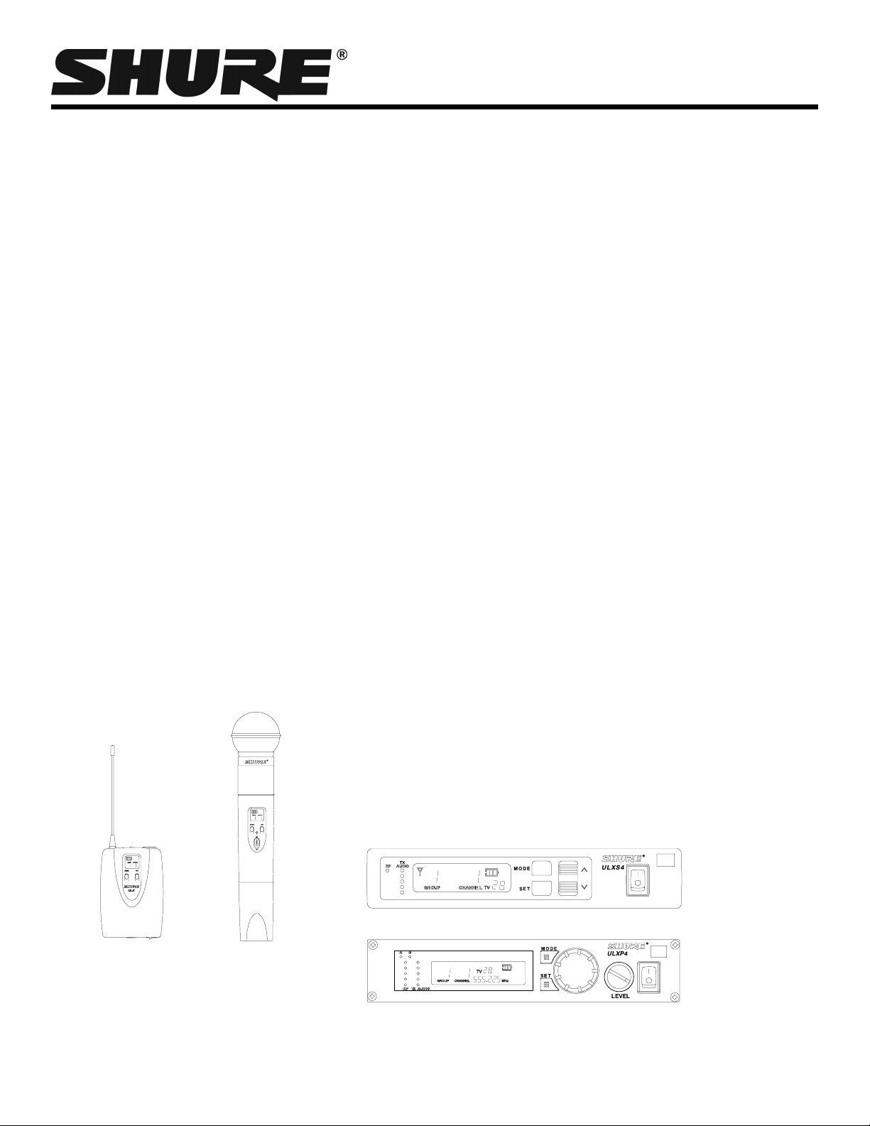
ULX1
2007 Shure Incorprated
TL1025 (Rev. 1)
ULX2
ULXS4
ULXP4
Page 2
ULX WIRELESS SYSTEM
SPECIFICATIONS
NOTE: For a list of compatible frequencies that are usable in
your area, refer to the supplied frequency supplement.
RF Carrier Frequency Range
554.000 to 865.000 MHz (Available frequencies depend on the
applicable regulations in the country where the system is used).
Refer to the frequency supplement supplied with the system.
Effective Range
100 m (300 ft.) under optimal conditions
NOTE: Actual working range depends on RF signal absorp-
tion, reflection, and interference
Audio Frequency Response
25 to 15,000 Hz, ±2 dB
NOTE: Overall system frequency response depends on the mi-
crophone element.
*Output Level: Microphone Level = Line Level – 20 dB
Transmitter Audio Polarity
Positive pressure on microphone diaphragm (or positive voltage applied to tip of WA302 phone plug) produces positive voltage on pin 2 (with respect to pin 3 of low impedance output)
and the tip of the high impedance
Transmitter Gain Adjustment Range
ULX1: 25 dB
ULX2: 25 dB
Receiver Audio Output Level (±38 kHz deviation, 1 kHz tone)
XLR connector (into 600 ohm load): +3.9 dBV (line), –17 dBV
(mic)
1
/
inch connector (into 3000 ohm load)
4
Impedance
ULX1 (input): 1 Megohm
ULXS4, ULXP4 (output): 50 ohms at line level; 2000 ohms at
mic level
Modulation
±38 kHz deviation compressor-expander system with pre- and
de-emphasis.
RF Power Output
ULX1, ULX2: 30 mW maximum
Dynamic Range
>100 dB, A-weighted
1
/4-inch output
–2 dBV
:
Specification Sheet
RF Sensitivity
1.26 µV for 12 dB SINAD (typical)
Image Rejection
80 dB typical
Spurious Rejection
75 dB typical
Ultimate Quieting (reference ±38 kHz deviation)
>105 dB, A-weighted
System Distortion (reference ±38 kHz deviation, 1 kHz modu-
lation)
0.3% total harmonic distortion, typical
Power Requirements
ULX1, ULX2: 9V alkaline battery (Duracell MN1604 recommended); 8.4V Nicad optional
ULXS4, ULXP4: 14 - 18 Vdc (negative ground), 550 mA
Battery Life
8 to 9 hours (with 9V Duracell MN1604 alkaline battery)
Operating Temperature Range
-20° to 49° C (–4° to 120° F)
NOTE: Battery characteristics may limit this range.
Overall Dimensions
ULX1: 96.5 mm H x 67 mm W x 26.7 mm D (3.86 x 2.68 x
1.10 in.)
ULX2/58, ULX2/BETA 58: 241 mm L x 51 mm Dia. (9.5 x 2 in.)
ULX2/87, ULX2/BETA 87: 216 mm L x 51 mm Dia. (8.5 x 2 in.)
ULX4S: 43 mm H x 214 mm W x 163 mm D (1.72 in. x 8.56 in.
x 6.52 in.)
ULX4P: 43 mm H x 214 mm W x 172 mm D (1.72 in. x 8.56 in.
x 6.88 in.)
Net Weight
ULX1: 79 g (2.8 oz.) without battery
ULX2/58, ULX2/BETA 58: 295 g (10.4 oz.) without battery
ULX2/87, ULX2/BETA 87: 193 g (6.8 oz.) without battery
ULXS4: 1049 g (2 lbs, 5 oz.)
ULXP4: 1105 g (2 lbs, 7 oz.)
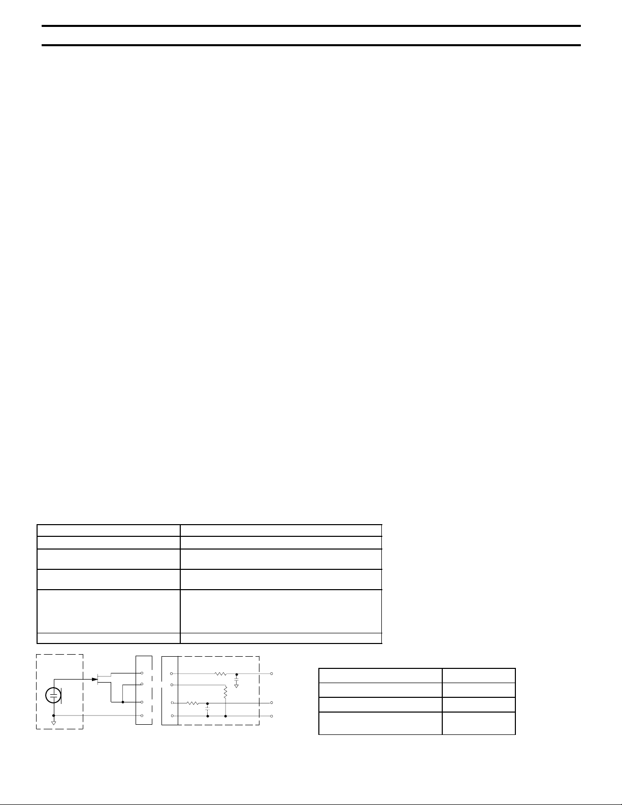
ULX1 Transmitter Input (Figure 1)
Connector: TA4F
Input Configuration: Unbalanced, active
Actual Impedance:
Maximum Input Level:
TA4F Connector Pin Assignments:
Voltage for Remote Power: +5 V supplied to microphone cartridge
MICROPHONE
ELEMENT
NOTE: LAVALIER MIC TIES PINS 3 AND 4 TOGETHER; THE GUITAR CABLE DOES NOT.
2
4
3
1
10 Vp–p (12 dBV) for 1% THD at minimum gain setting
ULX1 MIC JACK BOARD
2
4
3
500 Ω
1
FIGURE 1
18 kΩ with lavalier microphone
1 MΩ with instrument cable
using 1 kHz signal.
Pin 1: Tied to Ground
Pin 2: Tied to +5 V
Pin 4: Tied thru 20kΩ Resistor to Ground.
(On instrument adapter cable, Pin 4 floats)
500 Ω
27 pF
Pin 3: Tied to Audio
27 pF
20K Ω
+5 V
AUDIO
GROUND
ULX1 Transmitter Output
Actual Impedance: 50 Ω
Nominal Output Level: 20 mW
Maximum Output Level: 30 mW
Pin Assignments: Shell = Ground
2
Center = Signal
Page 3

ULX WIRELESS SYSTEM
REPLACEMENT PARTS
AC Adapter (120 VAC, 60 Hz) PS40
AC Adapter (230 VAC, 50/60 Hz, Europlug) PS40E
AC Adapter (230 VAC, 50/60 Hz, UK) PS40UK
AC Adapter (90 VAC, 50/60 Hz) PS40J
SM58 Cartridge with Grille (ULX2/58) R158
BETA 58 Cartridge with Grille (ULX2/BETA 58) R178
SM87A Cartridge with Grille (ULX2/87) R165
BETA 87A Cartridge with Grille (ULX2/BETA
87A)
BETA 87C Cartridge with Grille (ULX2/BETA
87C)
Matte Silver Grille (ULX2/58) RK143G
FURNISHED ACCESSORIES
Microphone Stand Adapter (ULX2) WA371
Grip/Switch Cover (ULX2) WA555
Zipper Bag (ULX1) 26A13
OPTIONAL ACCESSORIES
UHF Line Amplifier UA830WB
UHF Powered Directional Antenna UA870WB
UHF Antenna Power Distribution Amplifier
(U.S.A.)
UHF Antenna Power Distribution Amplifier (Eu-
rope)
UHF Antenna Power Distribution Amplifier (UK) UA844UK
1/4 Wave Antenna (748–865 MHz) UA400
1/4 Wave antenna (554–698 MHz) UA400B
1/2 Wave Antenna (774–865 MHz) UA820A
1/2 Wave Antenna (690–746 MHz) UA820B
R166
RPW100
UA844US
UA844E
Specification Sheet
Matte Silver Grille (ULX2/BETA 58) RK265G
Matte Silver Grille (ULX2/BETA 87A) RK313
Matte Silver Grille (ULX2/BETA 87C) RK312
Black Grille (ULX2/87) RK214G
Black Grille (ULX2/BETA 58) RK323G
Black Grille (ULX2/BETA 87A) RK324G
Belt Clip 44A8013A
1
/4-Wave Antenna (554 - 698 MHz) 95A8699
1
/4-Wave Antenna (748 - 865 MHz) 95B8699
1
/2-Wave Antenna (748 - 865 MHz) 95A8783
1
/2-Wave Antenna (662 - 698 MHz) 95C8783
1
/2-Wave Antenna (554 - 590 MHz) 95D8783
Zipper Bag (ULX2) 26A14
Screwdriver 80A498
1/2 Wave Antenna (554–590 MHz) UA820D
1/2 Wave Antenna (662–698 MHz) UA820C
1/2 Wave Antenna (746–784 MHz) UA820E
33 m (100 ft.) BNC–BNC cable UA8100
1.8 m (6 ft.) BNC–BNC cable UA806
Antenna Rack Panel Kit UA440
Rack Mount Kit for Two Receivers UA507
Carrying Case WA610
Remote Antenna Bracket with BNC Bulkhead
Adapter
Rack Mount Kit for Single Receiver UA506
UA505
3
Page 4

ULX WIRELESS SYSTEM
Specification Sheet
Architects’ and Engineers’ Specifications
The wireless system shall operate in the UHF band between 554 MHz and 865 MHz, with the specific available frequency range being
dependent on the user’s locale. Effective range of the system, receiver to transmitter, shall be 100 meters (300 ft.), under optimal conditions.
The system shall allow selection of over 1400 operating frequencies across 36 MHz of bandwidth in order to avoid RF interference. Optimal
frequencies shall be selected automatically , ensuring that individual systems run at their highest level of performance, and that multiple systems in simultaneous use do not interfere with one another.
Each transmitter shall be powered by a single 9V battery . Transmitters shall have a power on/of f switch, as well as a backlit LCD showing group and channel, peak indication, and battery strength. Available transmitters shall include a body pack for use with electric guitars,
basses, and other electric instruments, as well as lavalier or headset microphones, and a handheld microphone for vocals. The body pack
shall include a –20dB pad switch to compensate for higher- or lower-gain devices.
The receiver shall have a multi-function display showing group, channel, frequency, squelch level, transmitter battery strength, and
locked/unlocked status. The system shall use diversity technology to improve reception, minimize signal dropouts, and achieve the best
possible signal–to–noise ratio. Tone key squelch, and noise squelch circuitry shall be built in to the system to provide optimal sound quality
and minimize unwanted noise. The receiver shall include an RF meter, an audio level meter, and a volume control.
The system shall be the Shure ULX Wireless.
4
 Loading...