

Shure UHF MD, UHF Wireless System User Manual Supplement

CONTENTS
SPECIFICATIONS 2. . . . . . . . . . . . . . . . . . . . . . . . . . . . . . . . . . . . . . . . . . . . . .
FURNISHED ACCESSORIES 5. . . . . . . . . . . . . . . . . . . . . . . . . . . . . . . . . . . .
OPTIONAL ACCESSORIES 6. . . . . . . . . . . . . . . . . . . . . . . . . . . . . . . . . . . . . .
REPLACEMENT PARTS 6. . . . . . . . . . . . . . . . . . . . . . . . . . . . . . . . . . . . . . . .
UHF WIRELESS SYSTEM COMPATIBILITY GUIDE 7. . . . . . . . . . . . . . . .
MASTER LIST 8. . . . . . . . . . . . . . . . . . . . . . . . . . . . . . . . . . . . . . . . . . . . . . . . . .
UHF Wireless System
USER GUIDE SUPPLEMENT
MD (800–820 MHz)
27B8667 (AA)
2001, Shure Incorporated
Printed in U.S.A.

2
SPECIFICATIONS
RF Carrier Frequency Range
800–820 MHz
Working Range
U1, U2: 152.4 m, minimum, under typical conditions; 487.6 m line of sight
U1H: 275 m, minimum, under typical conditions; 975 m line of sight
NOTE: Actual working range depends on RF signal absorption, r eflection and
interference
Audio Frequency Response
50 to 15,000 Hz, ±2 dB. NOTE: Overall system frequency response depends on the
microphone element
Gain Adjustment Range
U1, U1H: 0 to 40 dB
U2: 0 to 26 dB
Modulation
±45 kHz deviation compressor-expander system with pre-and de-emphasis
RF Power Output
U1, U2: 10 mW maximum
U1H: 50 mW maximum
Dynamic Range
>102 dB, A-weighted
RF Sensitivity
U4S U4D
–110 dBm
12 dB SINAD
–107 dBm
12 dB SINAD
–105 dBm
30 dB SINAD
–102 dBm
30 dB SINAD
Image Rejection
90 dB typical
Spurious Rejection
75 dB typical
Ultimate Quieting (ref. 45 kHz deviation)
>100 dB, A-weighted
Audio Polarity
Positive pressure on microphone diaphragm (or positive voltage applied to tip of
WA302 phone plug) produces positive voltage on pin 2 with respect to pin 3 of
low impedance output and the tip of the high impedance
1
/4-inch output
System Distor tion (ref. ±45 kHz deviation, 1 kHz modulation)
0.3% Total Harmonic Distortion typical
Power Requirements
U1, U1H, U2: 1.5V A A alkaline battery ( Dur acell MN1500 recommended) ; Ni cad
optional
U4: 90 to 230 Vac , 50/60 Hz
Power Consumption:
U4S: 9.6 W min., 13.2 W max.
U4D: 12 W min.,16 W max.
UA840: 15 W min., 16 W max.
Battery Life (Typical)
U1, U2: 12 hours (with Duracell MN1500 1.5V AA alkaline battery)
U1H: 6 hours (with Duracell MN1500 1.5V AA alkaline battery)
3
Operating Temperature Range
-20° to 50° C NOTE: Battery characteristics may limit this range
Overall Dimensions
U1: 92.2 mm L x 64.7 mm W x 24.2 mm D
U2/58:254 mm L x 50.8 mm Dia.
U2/BETA 58: 254 mm L x 53.2 mm Dia.
U2/87:228.6 mm x 49.2 mm Dia.
U2/BETA 87: 216 mm L x 50.8 mm Dia
U4S/U4D: 44.5 mm H x 482.6 mm W x 295.3 mm D
Net Weight
U1, U1H: 175.2 g without battery
U2/58, U2/BETA 58: 375.6 g without battery
U2/87, U2/BETA 87: 303.1 g without battery
U4S: 3.30 kg
U4D: 3.85 kg
Certification
U1*, U2: BAPT Type Approved to FTZ 17TR 2019 and BAPT 122 R1; EMC
Approved to ETS 300 445.
U4S, U4D: VDE Certified to EN 60 950. BAPT Type Approved to FTZ 17TR 2019
and BAPT 122 R1; EMC Approved to ETS 300 445. Meets Low Voltage
Directive.
UHF Type Approved and EMC Approved systems are eligible to carry the CE
marking.
*The U1H transmitter does not carry the same approvals as the U1 transmitter.
U1, U1H Transmitter Input
Connector:
Switchcraft TA4F Tini Q-G or
LEMO connector (optional)
Input Configuration:
Unbalanced, active
Actual Impedance:
18 kΩ with lavalier microphone
1 MΩ with instrument cable
Maximum Input Level:
6 Vp–p (+7 dBV) for 1% THD at minimum gain
setting using 1 kHz signal.
TA4F Tini Q.G. Connector Pin
Assignments:
Pin 1: Tied to Ground
Pin 2: Tied to +5 V
Pin 3: Tied to Audio
Pin 4: Tied thru 20kΩ Resistor to Ground.
(On instrument adapter cable, Pin 4 floats)
LEMO Connector
Pin Assignments:
Pin 1: Tied to Pin 3 and 10 kΩ to Ground
Pin 2: +5V
Pin 3: Tied to Pin 1
Pin 4: Tied to Shield (Ground for Posit ive Bias)
Voltage for Re mote Power:
+5 V supplied to microphone cartridge
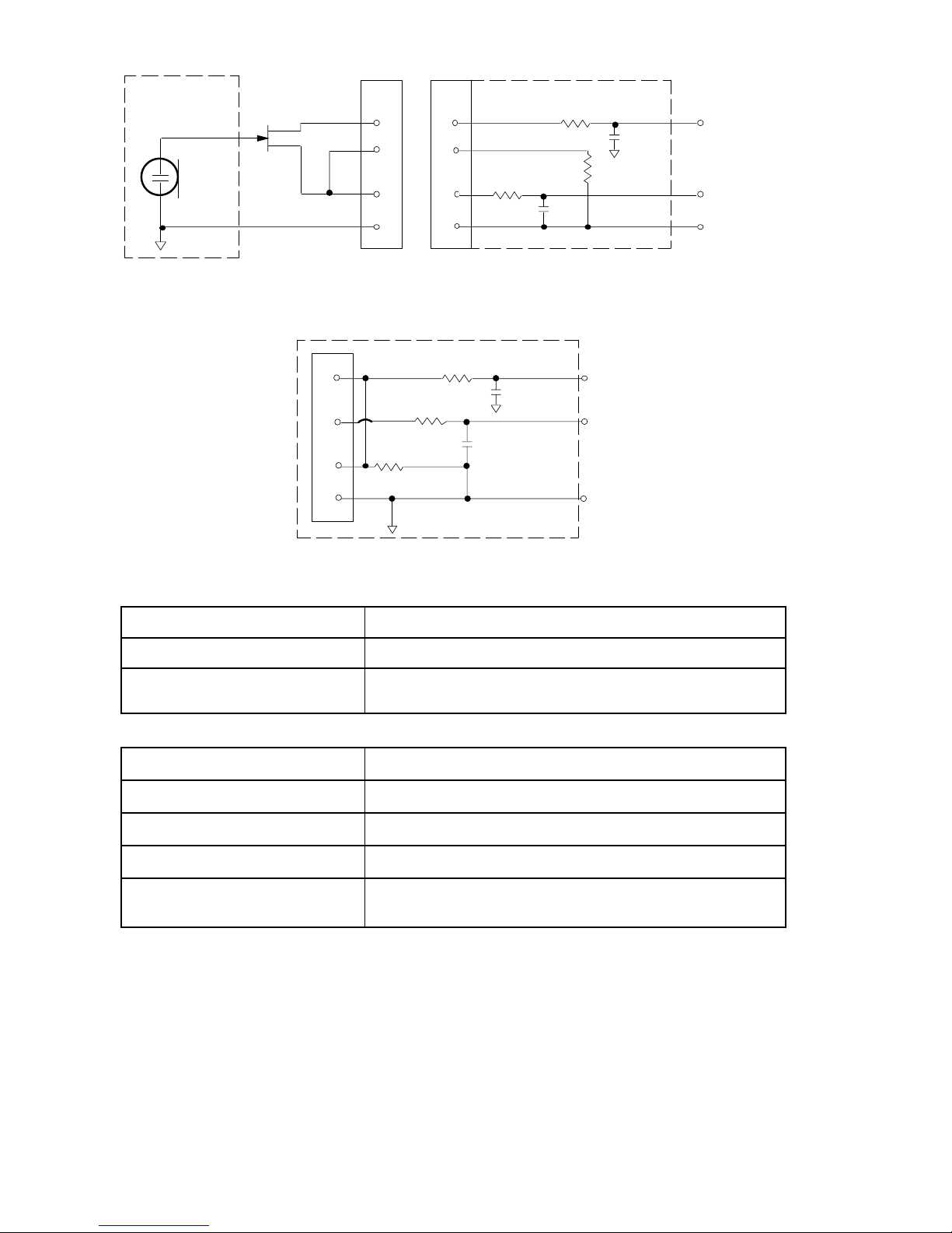
U1, U1H Transmitter Output (Figure 1)
Connector:
SMC
Actual Impedance:
50 Ω
Nominal Output Level:
+10 dBm (+17 dBm for U1H)
Maximum Output Level:
+11 dBm (+18 dBm for U1H)
Pin Assignments:
Shell = Ground
Center = Signal
4
27 pF
20K Ω
27 pF
+5 V
AUDIO
GROUND
U1/U1H MIC JACK BOARD
2
1
4
500 Ω
500 Ω
MICROPHONE
ELEMENT
3
2
1
3
4
NOTE: LAVALIER MIC TIES PINS 3 AND 4
TOGETHER; GUITAR CABLE DOES NOT.
27 pF
499 Ω
499 Ω
3
27 pF
10K Ω
AUDIO
SHIELD
U1L (LEMO 4 PIN) MIC JACK BOARD
1
4
2
BIAS
FIGURE 1
U2 Transmitter Input
Input Configuration: Unbalanced, active
Actual Impedance: 20 kΩ
Maximum Input Level: 3 Vp–p (0.5 dBV) for 1% THD at minimum gain setting
using 1 kHz signal.
U2 Transmitter Output
Connector:
SMC
Actual Impedance:
50 Ω
Nominal Output Level:
+10 dBm
Maximum Output Level:
+11 dBm
Pin Assignments:
Shell = Ground
Center = Signal

5
U4S and U4D Receiver Input
Connector: Antenna Power Input Network Interface
Connector Type: BNC IEC 25–Pin D
Actual Impedance: 50 Ω –– ––
Nominal Input
Level:
–95 to –30 dBm 90–230 VAC,
50/60 Hz
CMOS Logic
Maximum Input
Level:
+6 dBm
(–20 dBm
recommended)
230 VAC, 50/60 Hz ––
Pin Assignments: Shell = Ground
Center = Signal
IEC Standard ––
Voltage for
Remote Power:
12 Vdc, 150 mA
maximum
–– 5V, 700 mA max.
U4S and U4D Receiver Output
Connector: Monitor Power
Output
High Z
Audio
Low Z
Audio*
Network
Interface
Output
Configuration:
Unbalanced
mono, 1/4 inch
–– Un-
balanced
Balanced See
Appendix
Actual
Impedance:
300 Ω –– 1 kΩ 30 Ω See
Appendix
Nominal
Input Level:
–– 90 to 230
VAC, 5A
–– –– CMOS
Logic
Pin
Assignments:
Tip = Hot
Ring = Hot
Sleeve = Gnd
IEC
Standard
Tip = Hot
Ring/
Sleeve =
Gnd
1 = Ground
2 = Hot
3 = Hot
See
Appendix
Voltage/
Current/
Phantom
Power
Protection?
Yes –– Yes Yes 5V, 700 mA
resettable
polyfuse
*Output Level: Microphone Level = Line Level – 30 dB
FURNISHED ACCESSORIES
Microphone Stand Adapter (U2) WA370A. . . . . . . . . . . . . . . . . . . . . . . . . . . . . . . . . . .
Zipper Bag (U1) 26A13. . . . . . . . . . . . . . . . . . . . . . . . . . . . . . . . . . . . . . . . . . . . . . . . . . .
Zipper Bag (U2) 26A14. . . . . . . . . . . . . . . . . . . . . . . . . . . . . . . . . . . . . . . . . . . . . . . . . . .
Screwdriver 80A498. . . . . . . . . . . . . . . . . . . . . . . . . . . . . . . . . . . . . . . . . . . . . . . . . . . . .
Coaxial Antenna Cable (2 ft) UA802. . . . . . . . . . . . . . . . . . . . . . . . . . . . . . . . . . . . . . . .
1/2 Wave Antenna UA820A. . . . . . . . . . . . . . . . . . . . . . . . . . . . . . . . . . . . . . . . . . . . . . . .
Transmitter Carrying Case 65A8257. . . . . . . . . . . . . . . . . . . . . . . . . . . . . . . . . . . . . . . .
Carrying Case Insert 29B1577. . . . . . . . . . . . . . . . . . . . . . . . . . . . . . . . . . . . . . . . . . . . .

6
OPTIONAL ACCESSORIES
Instrument Adapter Cable (U1) WA302. . . . . . . . . . . . . . . . . . . . . . . . . . . . . . . . . . . . . .
Switchcraft TA4F Female 4–Pin Connector (U1) WA330. . . . . . . . . . . . . . . . . . . . . . . .
In-Line Audio Switch (U1) WA360. . . . . . . . . . . . . . . . . . . . . . . . . . . . . . . . . . . . . . . . . . .
1.8 Meter (6 ft) Receiver-Mixer Cable (1/4” phone to XLR) WA410. . . . . . . . . . . . . . . .
7.6 Meter (25 ft) Antenna Extension Cable UA825. . . . . . . . . . . . . . . . . . . . . . . . . . . .
15.2 (50 ft) Meter Antenna Extension Cable UA850. . . . . . . . . . . . . . . . . . . . . . . . . . .
In–Line Active Remote Antenna Kit (800 – 830 MHz) UA830C. . . . . . . . . . . . . . . . . .
Antenna/Power Distribution System, 230 Vac UA845MB. . . . . . . . . . . . . . . . . . . . . . .
Directional Antenna UA870MB. . . . . . . . . . . . . . . . . . . . . . . . . . . . . . . . . . . . . . . . . . . . .
REPLACEMENT PARTS
Hardware Kit (screwdriver, mounting feet, cable clamps) 90VL1371. . . . . . . . . . . . .
Bulkhead Adapters for Front–Mounting Antennas 95A8647. . . . . . . . . . . . . . . . . . . .
230 VAC Power Cord (Schuko mains connector) 95A8247. . . . . . . . . . . . . . . . . . . . .
304 mm (12 in.) Daisy–Chain Power Cord (230 V) 95A8678. . . . . . . . . . . . . . . . . . . .
SM58 Cartridge with Grille (U2/58) R158. . . . . . . . . . . . . . . . . . . . . . . . . . . . . . . . . . . .
BETA 58A Cartridge with Grille (U2/BETA 58) R179. . . . . . . . . . . . . . . . . . . . . . . . . . .
SM87 Cartridge with Grille (U2/87) R165. . . . . . . . . . . . . . . . . . . . . . . . . . . . . . . . . . . .
BETA 87 Cartridge with Grille (U2/BETA 87) R166. . . . . . . . . . . . . . . . . . . . . . . . . . . .
Matte Silver Grille (U2/58) RK143G. . . . . . . . . . . . . . . . . . . . . . . . . . . . . . . . . . . . . . . . . .
Matte Silver Grille (U2/BETA 58) RK265G. . . . . . . . . . . . . . . . . . . . . . . . . . . . . . . . .
Matte Silver Grille (U2/BETA 87 RK313G. . . . . . . . . . . . . . . . . . . . . . . . . . . . . . . . . .
Black Grille (U2/87) RK214G. . . . . . . . . . . . . . . . . . . . . . . . . . . . . . . . . . . . . . . . . . . . . . .
Black Grille (U2/BETA 58) RK323G. . . . . . . . . . . . . . . . . . . . . . . . . . . . . . . . . . . . . . . . . .
Black Grille (U2/BETA 87) RK324G. . . . . . . . . . . . . . . . . . . . . . . . . . . . . . . . . . . . . . . . . .
Belt Clip (U1) 53A8247A. . . . . . . . . . . . . . . . . . . . . . . . . . . . . . . . . . . . . . . . . . . . . . . . . .
Antenna (U1) 95A8646. . . . . . . . . . . . . . . . . . . . . . . . . . . . . . . . . . . . . . . . . . . . . . . . . . .
Antenna (U2) 95A2029. . . . . . . . . . . . . . . . . . . . . . . . . . . . . . . . . . . . . . . . . . . . . . . . . . .
 Loading...