

Page 1

UHF Wireless System
USER GUIDE SUPPLEMENT UA (782-806 MHz)
CONTENTS
SPECIFICATIONS.................................................................................2
Furnished Accessories ......................................................................... 6
Optional Accessories ............................................................................ 6
Replacement Parts ................................................................................6
FREQUENCY SELECTION GUIDE ......................................................7
Compatibility Groups .............................................................................7
Compatible Frequency List .................................................................... 8
UHF TV Channel Guide (for U.S. Channels 66-69)............................... 9
Master List ........................................................................................... 10
©2003 Shure Incorporated
27C8591 (Rev. 4)
Printed in U.S.A.
Page 2

SPECIFICATIONS
RF Carrier Frequency Range
782-806 MHz
Working Range
U1: 152.4 m (500 ft) minimum, under typical conditions; 487.6 m (1600 ft ) line of
sight
U1H: 300 m (1000 ft.) minimum, under typical conditions; 975.2 m (3200 ft) line of
sight
NOTE: Actual working range depends on RF signal absorption, reflection and interference
Audio Frequency Response
50 to 15,000 Hz, ±2 dB. NOTE: Overall system frequency response depends on the
microphone element
Gain Adjustment Range
U1, U1H: 0 to 40 dB
U2: 0 to 26 dB
Modulation
±45 kHz deviation compressor-expander system with pre-and de-emphasis
RF Power Output
U1, U2: 10 mW maximum
U1H: 100 mW maximum
Dynamic Range
>102 dB, A-weighted
RF Sensitivity
U4S U4D
-110 dBm
12 dB SINAD
-105 dBm
30 dB SINAD
Image Rejection
90 dB typical
Spurious Rejection
75 dB typical
Ultimate Quieting (ref. 45 kHz deviation)
>100 dB, A-weighted
Audio Polarity
Positive pressure on microphone diaphragm (or positive voltage applied to tip of
WA302 phone plug) produces positive voltage on pin 2 with respect to pin 3 of low
impedance output and the tip of the high impedance 1/4-inch output
System Distortion (ref. ±45 kHz deviation, 1 kHz modulation)
0.3% Total Harmonic Distortion typical
Power Requirements
U1, U1A, U2: 1.5V AA alkaline battery; Nicad optional
U4: 90 to 230 Vac, 50/60 Hz
Power Consumption
U4S: 9.6 W min., 13.2 W max.
U4D: 12 W min.,16 W max.
UA840: 15 W min., 16 W max.
-107 dBm
12 dB SINAD
-102 dBm
30 dB SINAD
2
Page 3

Battery Life (Typical)
U1, U2: 12 hours (with 1.5V AA alkaline battery)
U1H: 6 hours (with 1.5V AA alkaline battery)
Operating Temperature Range
-20° to 50° C (-4° to 122° F) NOTE: Battery characteristics may limit this range
Overall Dimensions
U1, U1A: 98.4 mm L x 64.7 mm W x 24.6 mm D (3-7/8 x 2-1/2 x 31/32 in.)
U2/58:254 mm L x 50.8 mm Dia. (10 x 2 in.)
U2/BETA 58: 254 mm L x 53.2 mm Dia. (10 x 2-3/32 in.)
U2/87:228.6 mm x 49.2 mm Dia. (9 x 1-15/16 in.)
U2/BETA 87: 216 mm L x 50.8 mm Dia. (8-1/2 x 2 in.)
U4S/U4D: 44.5 mm H x 482.6 mm W x 295.3 mm D (1-3/4 x 19 x 11-5/8 in.)
Net Weight
U1, U1A: 175.2 g (6.1 oz.) without battery
U2/58, U2/BETA 58: 375.6 g (13.2 oz.) without battery
U2/87, U2/BETA 87: 303.1 g (10.7 oz) without battery
U4S: 3.30 kg (7.27 lbs)
U4D: 3.85 kg (8.48 lbs)
Certification
U1, U1A, U2: Type Accepted under FCC Parts 74. Certified by IC in Canada under
TRC-78.
U4S, U4D: UL and cUL Listed to UL 813 and CSA C22.2 No. 1. VDE Certified to EN
60 950. Approved under the Notification provision of FCC Part 15; Certified by IC in
Canada under TRC-78.
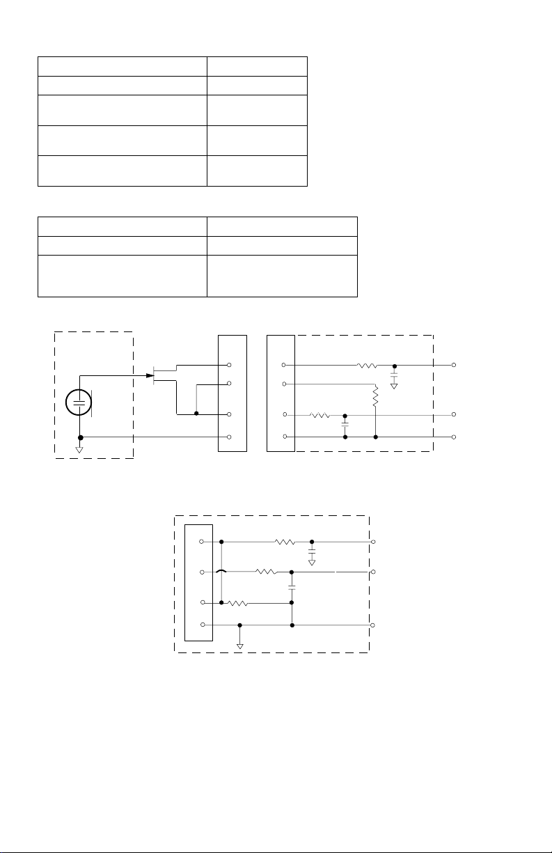
U1, U1H Transmitter Input (Figure 1)
Connector: 4-Pin female mini connector (TA4F) or
Input Configuration: Unbalanced, active
Actual Impedance: 18 kW with lavalier microphone
Maximum Input Level: 6 Vp-p (+7 dBV) for 1% THD at minimum gain setting
(TA4F) Connector Pin
Assignments:
LEMO Connector
Pin Assignments:
Pin 4: Tied to Shield (Ground for Positive Bias)
Voltage for Remote Power: +5 V supplied to microphone cartridge
LEMO connector (optional)
1 MW with instrument cable
using 1 kHz signal.
Pin 1: Tied to Ground
Pin 2: Tied to +5 V
Pin 4: Tied thru 20kW Resistor to Ground.
(On instrument adapter cable, Pin 4 floats)
Pin 1: Tied to Pin 3 and 10 kW to Ground
Pin 3: Tied to Audio
Pin 3: Tied to Pin 1
3
Pin 2: +5V
Page 4
U1, U1H Transmitter Output
Connector: SMC
Actual Impedance: 50 W
Nominal Output Level: +10 dBm (+17
dBm for U1H)
Maximum Output Level: +11 dBm (+18
dBm for U1H)
Pin Assignments: Shell = Ground
Center = Signal
U2 Transmitter Input
Input Configuration: Unbalanced, active
Actual Impedance: 20 kW
Maximum Input Level: 3 Vp-p (0.5 dBV) for 1% THD
at minimum gain setting
using 1 kHz signal.
MICROPHONE
ELEMENT
NOTE: LAVALIER MIC TIES PINS 3 AND 4
TOGETHER; GUITAR CABLE DOES NOT.
1
2
3
4
U1/U1H MIC JACK BOARD
2
2
4
4
500
3
3
499
1
499
AUDIO
27 pF
BIAS
27 pF
SHIELD
1
U1L(LEMO4PIN)MICJACKBOARD
10K
FIGURE 1
500
27 pF
20K
27 pF
+5 V
AUDIO
GROUND
4
Page 5

U2 Transmitter Output
Connector: SMC
Actual Impedance: 50 W
Nominal Output Level: +10 dBm
Maximum Output Level: +11 dBm
Pin Assignments: Shell = Ground
Center = Signal
U4S and U4D Receiver Input
Connector: Antenna Power Input Network
Interface
Connector Type:
Actual
BNC IEC 25-Pin D
50 W -- --
Impedance:
Nominal Input
Level:
Maximum Input
Level:
Pin
Assignments:
Voltage for
Remote Power:
-95 to -30 dBm 90-230 VAC,
+6 dBm
(-20 dBm
recommended)
Shell = Ground
Center = Signal
12 Vdc, 150 mA
maximum
50/60 Hz
230 VAC, 50/60 Hz --
IEC Standard --
-- 5V, 700 mA max.
CMOS Logic
U4S and U4D Receiver Output
Connector: Monitor Power
Output
Configuration:
Actual
Impedance:
Nominal
Input Level:
Pin
Assignments:
Voltage/
Current/
Phantom
Power
Protection?
*Output Level: Microphone Level = Line Level - 30 dB
Unbalanced
mono, 1/4 inch
300 W -- 1 kW 30 W See
-- 90 to 230
Tip = Hot
Ring = Hot
Sleeve = Gnd
Yes -- Yes Yes 5V, 700 mA
Output
-- Unbalanced Balanced See
VAC, 5A
IEC
Standard
High Z
Audio
-- -- CMOS
Tip = Hot
Ring/ Sleeve =
Gnd
5
Low Z
Audio*
1 = Ground
2 = Hot
3 = Hot
Network
Interface
Appendix
Appendix
Logic
See
Appendix
resettable
polyfuse
Page 6

FURNISHED ACCESSORIES
Microphone Stand Adapter (U2).....................................................WA370A
Zipper Bag (U1)..................................................................................26A13
Zipper Bag (U2)..................................................................................26A14
Screwdriver .....................................................................................80A498
Coaxial Antenna Cable (2 ft) ............................................................. UA802
1/2 Wave Antenna...........................................................................UA820A
Transmitter Carrying Case .............................................................65A8257
Carrying Case Insert ......................................................................29B1577
OPTIONAL ACCESSORIES
Instrument Adapter Cable (U1) ........................................................ WA302
Female 4-Pin Mini Connector (TA4F) (U1)....................................... WA330
In-Line Audio Switch (U1) ................................................................ WA360
1.8 Meter (6 ft) Receiver-Mixer Cable (1/4" phone to XLR) ............. WA410
7.6 Meter (25 ft) Antenna Extension Cable....................................... UA825
15.2 (50 ft) Meter Antenna Extension Cable.....................................UA850
In-Line Active Remote Antenna Kit (782 - 810 MHz) ......................UA830A
Antenna/Power Distribution System, 120 Vac.................................UA840A
Directional Antenna.........................................................................UA870A
REPLACEMENT PARTS
Hardware Kit (screwdriver, mounting feet, cable clamps)............90VL1371
Bulkhead Adapters for Front-Mounting Antennas ..........................95A8647
120 VAC Power Cord (U.S. mains connector) ...............................95A8389
305 mm (12 in.) Daisy-Chain Power Cord (120 V).........................95A8570
â
Cartridge with Grille (U2/58)................................................... R158
SM58
BETA 58A
â
Cartridge with Grille (U2/BETA 58).................................. R179
SM87 Cartridge with Grille (U2/87) ..................................................... R165
BETA 87A Cartridge with Grille (U2/BETA 87A).................................. R166
BETA 87C Cartridge with Grille (U2/BETA 87C) ............................RPW100
Matte Silver Grille (U2/58).............................................................. RK143G
Matte Silver Grille (U2/BETA 58)............................................... RK265G
Matte Silver Grille (U2/BETA 87A) ............................................ RK313G
Black Grille (U2/87C) .................................................................... RK214G
Black Grille (U2/BETA 58) .............................................................. RK323G
Black Grille (U2/BETA 87A) ........................................................... RK324G
Belt Clip (U1)...............................................................................53A8247A
Antenna (U1)..................................................................................95A8646
Antenna (U2)..................................................................................95A2029
6
Page 7

FREQUENCY SELECTION GUIDE
The Shure UHF Wireless System is designed for maximum flexibility and versatility
in a variety of applications. Up to 20 Shure UHF Wireless Systems can be operated simultaneously in a single installation using the frequency compatibility groups. Groups
A1 and A2 are included in a “master list” that covers all frequencies in the 782 to 806
MHz band. When using the U4D dual receiver, maintain a minimum of 500 kHz separation between each receiver in the U4D. Please contact the Shure Customer Service Department If you need additional information or assistance in frequency selection and
setup.
COMPATIBILITY GROUPS
The Shure UHF Wireless System includes seven groups of compatible channels. If
you are using more than one receiver in the same area, we recommend that you set the
receivers to different frequencies within the same group.
Use frequencies from Groups 1-3 in locations where TV channels 66, 67, 68, and 69
are NOT in use. If any of these TV channels are present in your location, use frequencies from one of the Groups 4-7 as indicated in the following table. Use the UHF TV
Channel Guide in this supplement to determine which TV channels may be present in
your area.
NOTE: The Group and Channel for any frequency in the UHF band as well as the TV
channel corresponding to that frequency is displayed on the U4 receiver. If the
receiver displays a TV channel that is active in your area for a frequency you have
selected, choose a different frequency.
TV CHANNEL
PRESENT
None 66, 67, 68, 69 Groups 1-3, 4-7
66 67, 68, 69 Group 4
67 66, 68, 69 Group 5
68 66, 67, 69 Group 6
69 66, 67, 68 Group 7
OPEN UHF
CHANNELS
RECOMMENDED UHF WIRELESS
FREQUENCY GROUP
7
Page 8

COMPATIBLE FREQUENCY LIST
The following table lists the frequencies in each of the seven compatibility groups.
Fewer channels are available in Groups 4-7.
TV
TV CHANNELS 66, 67, 68, 69 OPEN
Group
1
CHANNEL
1 782.750 783.125 782.625 788.500 782.625 783.125 782.125
2 783.375 783.750 783.125 789.000 784.250 783.750 783.000
3 785.125 784.625 783.875 790.125 785.125 784.750 783.625
4 786.000 785.750 785.625 790.875 786.375 785.500 784.875
5 787.250 786.500 787.875 792.250 787.125 786.875 785.875
6 788.250 788.125 789.125 793.000 794.125 788.750 787.250
7 788.875 788.875 789.875 796.500 795.250 789.750 788.375
8 790.000 790.250 791.125 798.000 796.875 790.375 789.000
9 790.875 791.000 792.875 798.750 797.625 791.625 789.875
10 792.250 792.875 793.375 799.750 799.250 793.125 790.375
11 795.250 796.500 794.875 800.500 800.375 800.500 792.875
12 796.000 797.875 795.375 801.875 802.375 801.000 794.125
13 797.625 798.625 796.125 802.500 802.875 801.750 795.625
14 798.750 799.750 798.250 803.500 803.625 803.500 796.375
15 800.250 800.375 799.625 804.250 804.625 804.125 798.125
16 800.750 801.375 801.375 804.750 805.125 805.000 799.000
17 802.500 803.375 802.125 805.500 - 805.625 799.625
18 803.500 803.875 803.375 - - - -
19 805.000 805.125 804.875 - - - -
20 805.750 805.750 805.625 - - - -
Group
2
Group
3
CHANNEL
66
PRESENT
Group
4
TV
CHANNEL
67
PRESENT
Group
5
TV
CHANNEL
68
PRESENT
Group
6
TV
CHANNEL
69
PRESENT
Group
7
8
Page 9

UHF TV CHANNEL GUIDE (FOR U.S. CHANNELS 66-69)
The following table identifies U.S. cities that have UHF TV stations operating on TV
Channels 66, 67, 68, and 69. Shure recommends that you operate your wireless system
only on TV channels other than those listed for your location.
STATE CITY TV
Alabama Birmingham 68 Michigan East Lansing 69
Opelika-Auburn 66 Flint 66
Troy 67 New Jersey Newark 68
California Los Angeles 68 West Milford 66
Salinas-
Monterrey
Novato 69 Smithtown 67
San Diego 69 Springville 67
Vallejo 66 Syracuse 68
Florida Bradenton 66 North Carolina Bryson City 67
Cocoa 68 Forest City 66
Hollywood 69 High Point 67
Lake Worth 67 Ohio Canton 67
Georgia Atlanta 69 Mansfield 68
Toccoa 68 Springfield 66
Hawaii Lihue 67 Pennsylvania Allentown 69
Illinois Danville 68 Erie 66
Elgin 66 Rhode Island Block Island 69
Galesburg 67 South Dakota Lowry 68
Joliet 66 Tennessee Lebanon 66
Indiana Anderson 67 Texas Alvin 69
Indianapolis 69 Arlington 68
Iowa Des Moines 69 Virginia Fredericksburg 69
Kentucky Louisville 68 Grundy 68
Morehead 67 Manassas 66
Paintsville 69 Washington Olympia 67
Maryland Baltimore 67 Wisconsin Fond du Lac 68
Hagerstown 68 West Virginia Fairmont 66
Massachussets Boston 68 Puerto Rico Humacoa 68
Marlborough 66
CHANNEL
67 New York Ilion 67
STATE CITY TV
CHANNEL
9
Page 10

MASTER LIST
The Shure “Master List” (Groups A1-A3) is a comprehensive index of all system frequencies. Note that not all “Master List” channels are compatible.
FREQUENCY
782.125 66 A1/1 788.250 67 A1/50
782.250 66 A1/2 788.375 67 A1/51
782.375 66 A1/3 788.500 67 A1/52
782.500 66 A1/4 788.625 67 A1/53
782.625 66 A1/5 788.750 67 A1/54
782.750 66 A1/6 788.875 67 A1/55
782.875 66 A1/7 789.000 67 A1/56
783.000 66 A1/8 789.125 67 A1/57
783.125 66 A1/9 789.250 67 A1/58
783.250 66 A1/10 789.375 67 A1/59
783.375 66 A1/11 789.500 67 A1/60
783.500 66 A1/12 789.625 67 A1/61
783.625 66 A1/13 789.750 67 A1/62
783.750 66 A1/14 789.875 67 A1/63
783.875 66 A1/15 790.000 67 A1/64
784.000 66 A1/16 790.125 67 A1/65
784.125 66 A1/17 790.250 67 A1/66
784.250 66 A1/18 790.375 67 A1/67
784.375 66 A1/19 790.500 67 A1/68
784.500 66 A1/20 790.625 67 A1/69
784.625 66 A1/21 790.750 67 A1/70
784.750 66 A1/22 790.875 67 A1/71
784.875 66 A1/23 791.000 67 A1/72
785.000 66 A1/24 791.125 67 A1/73
785.125 66 A1/25 791.250 67 A1/74
785.250 66 A1/26 791.375 67 A1/75
785.375 66 A1/27 791.500 67 A1/76
785.500 66 A1/28 791.625 67 A1/77
785.625 66 A1/29 791.750 67 A1/78
785.750 66 A1/30 791.875 67 A1/79
785.875 66 A1/31 792.000 67 A1/80
786.000 66 A1/32 792.125 67 A1/81
786.125 66 A1/33 792.250 67 A1/82
786.250 66 A1/34 792.375 67 A1/83
786.375 66 A1/35 792.500 67 A1/84
786.500 66 A1/36 792.625 67 A1/85
786.625 66 A1/37 792.750 67 A1/86
786.750 66 A1/38 792.875 67 A1/87
786.875 66 A1/39 793.000 67 A1/88
787.000 66 A1/40 793.125 67 A1/89
787.125 66 A1/41 793.250 67 A1/90
787.250 66 A1/42 93.375 67 A1/91
787.375 66 A1/43 793.500 67 A1/92
787.500 66 A1/44 793.625 67 A1/93
787.625 66 A1/45 793.750 67 A1/94
787.750 66 A1/46 793.875 67 A1/95
U.S. TV
CHANNEL
GROUP/
CHANNEL
FREQUENCY
U.S. TV
CHANNEL
GROUP/
CHANNEL
10
Page 11

FREQUENCY
U.S. TV
CHANNEL
GROUP/ CHANNEL
794.125 68 A2/2
794.250 68 A2/3
794.375 68 A2/4
794.625 68 A2/6
794.750 68 A2/7
794.875 68 A2/8
795.000 68 A2/9
795.125 68 A2/10
795.250 68 A2/11
795.375 68 A2/12
795.500 68 A2/13
795.625 68 A2/14
795.750 68 A2/15
795.875 68 A2/16
796.000 68 A2/17
796.125 68 A2/18
796.250 68 A2/19
796.375 68 A2/20
796.500 68 A2/21
796.625 68 A2/22
796.750 68 A2/23
796.875 68 A2/24
797.000 68 A2/25
797.125 68 A2/26
797.250 68 A2/27
797.375 68 A2/28
797.500 68 A2/29
797.625 68 A2/30
797.750 68 A2/31
797.875 68 A2/32
798.000 68 A2/33
798.125 68 A2/34
798.250 68 A2/35
798.375 68 A2/36
798.500 68 A2/37
798.625 68 A2/38
798.750 68 A2/39
798.875 68 A2/40
799.000 68 A2/41
799.125 68 A2/42
799.250 68 A2/43
799.375 68 A2/44
799.500 68 A2/45
799.625 68 A2/46
799.750 68 A2/47
799.875 68 A2/48
FREQUENCY
U.S. TV
CHANNEL
GROUP/CHANNEL
800.000 69 A2/49
800.250 69 A2/51
800.375 69 A2/52
800.500 69 A2/53
800.625 69 A2/54
800.750 69 A2/55
800.875 69 A2/56
801.000 69 A2/57
801.125 69 A2/58
801.250 69 A2/59
801.375 69 A2/60
801.500 69 A2/61
801.625 69 A2/62
801.750 69 A2/63
801.875 69 A2/64
802.000 69 A2/65
802.125 69 A2/66
802.250 69 A2/67
802.375 69 A2/68
802.500 69 A2/69
802.625 69 A2/70
802.750 69 A2/71
802.875 69 A2/72
803.000 69 A2/73
803.125 69 A2/74
803.250 69 A2/75
803.375 69 A2/76
803.500 69 A2/77
803.625 69 A2/78
803.750 69 A2/79
803.875 69 A2/80
804.000 69 A2/81
804.125 69 A2/82
804.250 69 A2/83
804.375 69 A2/84
804.500 69 A2/85
804.625 69 A2/86
804.750 69 A2/87
804.875 69 A2/88
805.000 69 A2/89
805.125 69 A2/90
805.250 69 A2/91
805.375 69 A2/92
805.500 69 A2/93
805.625 69 A2/94
805.750 69 A2/95
805.875 69 A2/96
11
Page 12

SHURE Incorporated Web Address: http://www.shure.com
5800 W. Touhy Avenue, Niles, IL 60714-4608, U.S.A.
Phone: 800-257-4873 Fax: 847-600-1212
In Europe, Phone: 49-7131-72140 Fax: 49-7131-721414
In Asia, Phone: 852-2893-4290 Fax: 852-2893-4055
Elsewhere, Phone: 847-600-2000 Fax: 847-600-6336
 Loading...