

Page 1
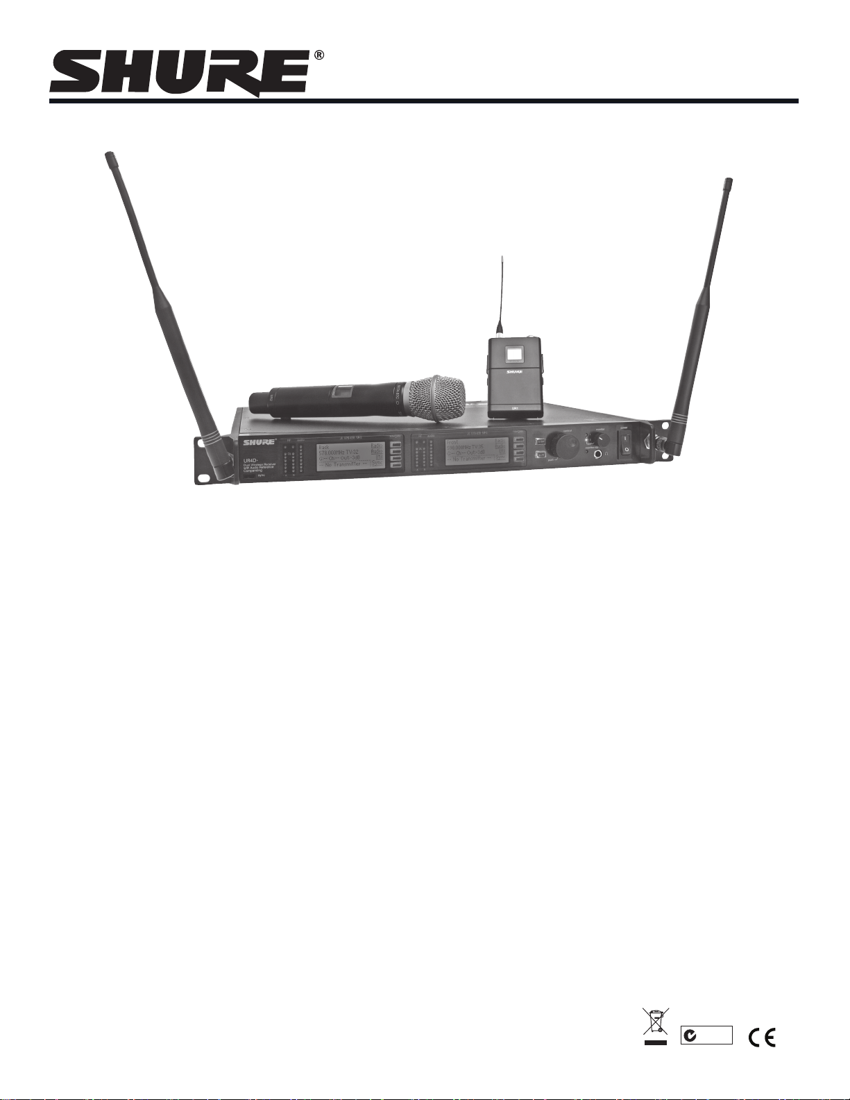
Model UHF-R® Wireless Systems
User Guide
Model UHF-R® Wireless User Guide .........................................................................................5
©2010 Shure Incorporated
27NS14492 (Rev. 1)
Printed in U.S.A.
N108
Page 2
English
! IMPORTANT SAFETY INSTRUCTIONS !
1. READ these instructions.
2. KEEP these instructions.
3. HEED all warnings.
4. FOLLOW all instructions.
5. DO NOT use this apparatus near water.
6. CLEAN ONLY with dry cloth.
7. DO NOT block any ventilation openings. Install in accordance with the manufacturer's instructions.
8. DO NOT install near any heat sources such as radiators, heat registers, stoves,
or other apparatus (including ampliers) that produce heat.
9. DO NOT defeat
the safety purpose of the polarized or grounding-type plug. A
polarized plug has two blades with one wider than the other. A grounding type
plug has two blades and a third grounding prong. The wider blade or the third
prong are provided for your safety. If the provided plug does not t into your outlet, consult an electrician for replacement of the obsolete outlet.
10. PROTECT the power cord from being walked on or pinched, particularly at plugs,
convenience receptacles, and the point where they e
xit from the apparatus.
11. ONLY USE attachments/accessories specied by the manufacturer.
12.
13. UNPLUG this apparatus during lightning storms or when unused for long periods of
time.
14. REFER all servicing to qualied service personnel. Servicing is required when the
apparatus has been damaged in any way, such as power-supply cord or plug is damaged, liquid has been spilled or objects have fallen into the apparatus, the apparatus
has been exposed to rain or
moistur
e, does not operate normally, or has been
dropped.
15. DO NOT expose the apparatus to dripping and splashing. DO NOT put objects lled
with liquids, such as vases, on the apparatus.
16. The MAINS plug or an appliance coupler shall remain readily operable.
17. The airborne noise of the apparatus does not exceed 70dB (A).
18. Apparatus with CLASS I construction shall be connected to a MAINS socket outlet
with a protective earthing connection.
19. To reduce the risk of re or electric shock, do not expose this apparatus to rain or
moisture.
20. Do not attempt to modify this product. Doing so could result in personal injury
and/or product failure.
USE only with a cart, stand, tripod, bracket, or table
specied by the manufacturer, or sold with the
apparatus. When a cart is used, use caution when
moving the cart/apparatus combination to avoid
injury from tip-over.
This symbol indicates that dangerous voltage constituting a
risk of electric shock is present within this unit.
WARNING:
Voltages in this equipment are hazardous to life. No user-serviceable parts inside. Refer all servicing to qualied service personnel. The
safety certications do not apply when the operating voltage is changed from the factory setting.
WARNING: This product contains a chemical known to the State of California to cause cancer and birth
defects or other reproductive harm.
! CONSIGNES DE SÉCURITÉ IMPORTANTES !
1. LIRE ces consignes.
2. CONSERVER ces consignes.
3. OBSERVER tous les avertissements.
4. SUIVRE toutes les consignes.
5. NE PAS utiliser cet appareil à proximité de l'eau.
6. NETTOYER UNIQUEMENT avec un chion sec.
7. NE PAS obstruer les ouvertures de ventilation. Installer en respectant les consignes du fabricant.
8. Ne pas installer à proximité d'une source de chaleur telle qu'un radiateur, une
bouche de chaleur, un poêle ou d'autres appar
duisant de la chaleur.
9. NE PAS détériorer la sécurité de la che polarisée ou de la che de terre. Une
che polarisée comporte deux lames dont l'une est plus large que l'autre. Une
che de terre comporte deux lames et une troisième broche de mise à la terre.
La lame la plus large ou la troisième broche assure la sécurité de l'utilisateur. Si
la che fournie ne s'adapte pas à la pr
de remplacer la prise hors normes.
10. PROTÉGER le cordon d'alimentation an que personne ne marche dessus et
que rien ne le pince, en particulier au niveau des ches, des prises de courant
et du point de sortie de l'appareil.
11. UTILISER UNIQUEMENT les accessoires spéciés par le fabricant.
Ce symbole indique la présence d'une tension dangereuse dans
l'appareil constituant un risque de choc électrique.
AVERTISSEMENT :
sonnel qualié. Les certications de sécurité sont invalidées lorsque le réglage de tension d'usine est changé.
Les tensions à l'intérieur de cet équipement peuvent être mortelles. Aucune pièce interne réparable par l'utilisateur. Coner toute réparation à du per-
eils (dont les amplicateurs) pro-
ise électrique, demander à un électricien
This symbol indicates that there are important operating and
maintenance instructions in the literature accompanying this unit.
12.
13. DÉBRANCHER l'appareil pendant les orages ou quand il ne sera pas utilisé pendant
longtemps.
14. CONFIE
si l'appareil est endommagé de quelque façon que ce soit, comme par exemple : cordon ou prise d'alimentation endommagé, liquide renversé ou objet tombé à l'intérieur
de l'appareil, exposition de l'appareil à la pluie ou à l'humidité, appareil qui ne marche
pas normalement ou que l'on a fait tomber.
15. NE PAS exposer cet appareil aux égout
des objets contenant de l'eau, comme des vases, sur l'appareil.
16. La prise SECTEUR ou un adaptateur d'alimentation doit toujours rester prêt(e) à être
utilisé(e).
17. Le bruit aérien de l'appareil ne dépasse pas 70 dB (A).
18. L'appareil de construction de CLASSE I doit être raccordé à une prise SECTEUR
dotée d'une protection par mise à la terre.
19. Pour réduire les risques d'incendie ou de choc électrique, ne pas exposer cet
appareil à la plu
20. Ne pas essayer de modier ce produit. Une telle opération est susceptible
d'entraîner des blessures ou la défaillance du produit.
3
UTILISER uniquement avec un chariot, un pied, un trépied,
un support ou une table spécié par le fabricant ou vendu
avec l'appareil. Si un chariot est utilisé, déplacer l'ensemble
chariot-appareil avec précaution an de ne pas le renverser,
ce qui pourrait entraîner des blessures.
R toute réparation à du personnel qualié. Des réparations sont nécessaires
tures et aux éclaboussements. NE PAS poser
ie ou à l'humidité.
Ce symbole indique que la documentation fournie avec l'appareil contient
des instructions d'utilisation et d'entretien importantes.
Page 3
Shure UHF-R Wireless
Este símbolo indica que la unidad contiene niveles de voltaje
peligrosos que representan un riesgo de choques eléctricos.
Este símbolo indica que la literatura que acompaña a esta
unidad contiene instrucciones importantes de funcionamiento
y mantenimiento.
Este símbolo indica que existem instruções operação e
manutenção importantes na literatura que acompanha esta
unidade.
! INSTRUCCIONES IMPORTANTES DE SEGURIDAD !
1. LEA estas instrucciones.
2. CONSERVE estas instrucciones.
3. PRESTE ATENCION a todas las advertencias.
4. SIGA todas las instrucciones.
5. NO utilice este aparato cerca del agua.
6. LIMPIESE UNICAMENTE con un trapo seco.
7. NO obstruya ninguna de las aberturas de ventilación. Instálese según lo
indicado en las instrucciones del fabricante.
8. No instale el aparato cerca de fuentes de calor tales como radiadores, registros
de calefac
ción, estufas u otros aparatos (incluyendo amplicadores) que
produzcan calor.
9. NO anule la función de seguridad del enchufe polarizado o con clavija de
puesta a tierra. Un enchufe polarizado tiene dos patas, una más ancha que la
otra. Un enchufe con puesta a tierra tiene dos patas y una tercera clavija con
puesta a tierra. La pata más ancha o la tercera clavija se proporciona para su
seguridad. Si el tomacorriente
sulte a un electricista para que sustituya el tomacorriente de estilo anticuado.
10. PROTEJA el cable eléctrico para evitar que personas lo pisen o estrujen, particularmente en sus enchufes, en los tomacorrientes y en el punto en el cual
sale del aparato.
11. UTILICE únicamente los accesorios especicados por el fabricante.
tipo apropiado para el enchufe, con-
no es del
12.
13. DESENCHUFE el aparato durante las tormentas eléctricas, o si no v
por un lapso prolongado.
14. TODA reparación debe ser llevada a cabo por técnicos calicados. El aparato
requiere reparación si ha sufrido cualquier tipo de daño, incluyendo los daños al
cordón o enchufe eléctrico, si se derrama líquido sobre el aparato o si caen objetos
en su interior, si ha sido expuesto a la lluvia o la humedad, si no funciona de modo
normal, o si se ha caído.
15. NO exponga este aparato
llenos con líquido, tales como oreros, sobre el aparato.
16. El enchufe de alimentación principal o acoplador de aparato electrodoméstico deberá
permanecer en condiciones de funcionamiento.
17. El nivel de ruido transmitido por el aire del aparato no excede de 70 dB (A).
18. Los aparatos de fabricación CLASE I deberán conectarse a un tomacorriente DE
ALIMENTACIÓN con clavija de pue
19. Para reducir el riesgo de causar un incendio o sacudidas eléctricas, no exponga
este aparato a la lluvia ni a humedad.
20. No intente modicar este producto. Hacerlo podría causar lesiones personales y/
o la falla del producto.
UTILICESE únicamente con un carro, pedestal, trípode,
escuadra o mesa del tipo especicado por el fabricante o vendido con el aparato. Si se usa un carro, el mismo debe moverse con sumo cuidado para evitar que se vuelque con el
aparato.
a chorr
os o salpicaduras de líquidos. NO coloque objetos
tierra protectora.
sta a
ADVERTENCIA : Los voltajes presentes en este equipo representan un riesgo para la vida. No contiene componentes reparables por el
usuario. Toda reparación debe ser llevada a cabo por técnicos calicados . Las certicaciones de seguridad no tienen vigencia cuando el
voltaje de funcionamiento de la unidad es cambiado a un valor distinto al ajustado en fábrica.
a a ser utilizado
! IMPORTANTES INSTRUÇÕES DE SEGURANÇA !
1. LEIA estas instruções.
2. GUARDE estas instruções.
3. PRESTE ATENÇÃO a todas as advertências.
4. SIGA todas as instruções.
5. NÃO use este aparelho perto de água.
6. LIMPE SOMENTE com um pano seco.
7. NÃO bloqueie nenhuma das aberturas de ventilação. Instale de acordo com as
instruções do fabricante.
8. NÃO instale próximo de nenhuma fonte de calor, tais como radiadores, bocais
de aquecimento, fornos ou outros aparelhos que pr
amplificadores).
9. NÃO inutilize as características de segurança do conector polarizado ou
com pino de aterramento. Um conector polarizado possui duas lâminas com
uma mais larga do que a outra. Um conector com pino de aterramento possui duas lâminas e um terceiro pino de aterramento. É fornecida uma
lâmina mais larga ou o terceiro pino para a sua segurança. Se por acaso o
conector não se encaixar na tomada, chame um eletricista para substituir a
tomada obsoleta.
10. PROTEJA o cabo de alimentação, evitando que seja pisado ou que enrosque,
especialmente nos conectores, nas tomadas elétricas de e
ponto onde elas saem do aparelho.
11.
USE SOMENTE acessórios/apetrechos especificados pelo fabricante
oduzam calor (inclusive
mprego geral e no
12.
13. DESLIGUE este aparelho da tomada elétrica durante tempestades com relâmpagos
ou quando não seja utilizado por longo período.
14. DEIXE toda a manutenção sob a responsabilidade de uma equipe de manutenção
qualificada. É necessário realizar a manutenção quando por algum motivo o aparelho tiver sido danificado de alguma forma, como por exemplo por
alimentação elétrica ou do seu conector, por derramamento de líquido ou queda de
objetos no aparelho, se o aparelho tiver sido exposto à chuva ou à umidade, não
esteja operando normalmente ou tenha sofrido queda.
15. NÃO exponha o aparelho a respingos ou goteiras. NÃO coloque objetos cheios
de líquidos, tais como vasos, em cima do aparelho.
16. A tomada de rede elétrica ou um acoplador do aparelho deve estar prontamente
operável.
17. O ruído aéreo do apar
18. O aparelho com construção CLASSE I deve estar conectado à tomada da rede elétrica com ligação à terra.
19. Para reduzir o risco de incêndio ou choque elétrico, não exponha este aparelho
20. Não tente alterar este produto. Isso poderá resultar em lesão pessoal e/ou falha
do produto.
Este símbolo indica que existe nesta unidade tensão perigosa
que apresenta risco de choque elétrico.
ATENÇÃO: As tensões neste equipamento podem causar acidentes fatais. Dentro dele não há nenhuma peça na qual se possa efetuar
manutenção. Deixe toda a manutenção a cargo de equipe de manutenção qualicada. As certicações de segurança perderão a validade
quando a tensão de operação ajustada na fábrica for alterada.
USE somente com um carrinho, pedestal, tripé,
suporte ou mesa especificados pelo fabricante ou
vendidos com o aparelho. Quando utilizar um carrinho, tenha cuidado ao movimentar o conjunto aparelho/carrinho para evitar danos com a queda do
mesmo.
elho não ultrapassa 70dB (A).
dano do cabo de
4
Page 4

English
Contents
Important Safety Instructions ............................................................................................................................................................... 3
Feature Overview ................................................................................................................................................................................ 6
System Components ........................................................................................................................................................................... 7
Receiver Controls and Connectors ...................................................................................................................................................... 8
Receiver LCD Interface ...................................................................................................................................................................... 9
Receiver Parameters ........................................................................................................................................................................... 9
Connecting Multiple Receivers to the RF Distribution Ports .............................................................................................................. 10
Automatic Frequency Selection ......................................................................................................................................................... 11
Networking Receivers ........................................................................................................................................................................ 12
Handheld and Bodypack Transmitter Controls and Connectors .......................................................................................................13
Transmitter LCD Interface ................................................................................................................................................................. 13
Transmitter Batteries ......................................................................................................................................................................... 13
Transmitter Parameters ..................................................................................................................................................................... 14
Setting Transmitter Gain .................................................................................................................................................................... 14
RF Safety Mode ................................................................................................................................................................................. 14
Automatic Transmitter Sync ..............................................................................................................................................................15
Troubleshooting ................................................................................................................................................................................. 16
Specifications ....................................................................................................................................................................................17
Replacement Parts and Accessories ................................................................................................................................................. 19
UHF-R Wireless System Compatibility Guide ...................................................................................................................................69
5
Page 5

Shure UHF-R Wireless
Feature Overview
The UHF-R
set up and operate with advanced features for professional installations requiring multiple wireless microphone systems.
Frequency Band Selection
Shure offers wireless systems in a selection of bands that conform to the different government regulations of specific nations or geographic
regions. These regulations help limit radio frequency (RF) interference among different wireless devices and prevent interference with local public
communications channels, such as television and emergency broadcasts.
The system’s band and frequency range are identified on the face of the receiver and transmitter. For example, “H4 518–578 MHz.”
For information on bands available in your area, consult your local dealer or phone Shure. More information is also available at
Shure’s website (www.shure.com).
Groups and Channels
To transmit audio through a wireless system, the transmitter and receiver must be set to the same radio frequency, or channel. A wide selection of channels
allows more microphones to be used at the same time, since each microphone must operate on a different channel. It also provides a greater choice of
open channels—those that are free from interference from television broadcasts, electronic devices, or other wireless systems.
A group is a selection of compatible channels. Wireless microphones work better together when set to channels in the same group.
Automatic Frequency Selection
The following features scan the RF environment to find the best group and channel settings for a particular installation.
Follow the steps on page 11 for instructions on using these features.
Automatic Transmitter Sync
This feature automatically transfers the group and channel settings from a receiver to a transmitter. You can also program other transmitter settings on a
receiver and transfer those settings too. See page 15.
Interface Lock
This feature locks the receiver and transmitters so that users cannot change settings. The transmitter power switch can also be disabled so that the
transmitter remains on if the power switch is accidentally toggled during a performance.
Audio Gain Structure
The following settings allow you to adjust audio gain throughout the system:
Networking
Each receiver has an RJ-45 port on the back for connecting to other receivers over an Ethernet network. Networking receivers allows you to automatically set channels for all the receivers with a single group scan command. You can also control and monitor all networked receivers through the Shure
Wireless Workbench PC software.
RF Distribution Ports
Use the RF distribution ports to share the signal from a single pair of antennas with up to 10 single or dual receivers within the same frequency band.
The RF ports eliminate the need for antenna splitters or distribution amplifiers. Active circuitry minimizes insertion losses, preserving signal quality.
Input filtering keeps the signal free from out-of-band interference. Distribution circuitry is active only when additional receivers are connected to the RF
distribution ports. When not used, the port circuitry is bypassed, allowing the receiver to be used as a stand-alone component.
Shure Wireless Workbench Software
The Shure Wireless Workbench software on the supplied CD includes a variety of useful tools for installing and managing multiple wireless systems.
Simply install the software on your computer and connect it to a network of receivers to monitor and control receivers and transmitters throughout the
network. (See page 12 for more information on networking).
Instructions on using the Wireless Workbench software are available in the online help files after you install the software.
®
Wireless Microphone System uses the latest wireless technology, delivers outstanding audio clarity, and is rugged and reliable. It is easy to
• Group Scan—finds the group with the most open channels, then sets all networked receivers to channels in that group.
• Channel Scan—finds the first open channel in the currently selected group and sets the receiver to that channel.
• Sensitivity (bodypack only). A 25 dB range of gain adjustment at the bodypack transmitter input.
• Transmitter Gain. A 30dB range of audio gain adjustment within the transmitter (affects audio level at the receiver, as indicated by the Audio
LEDS.)
• Output Level. 32 dB of attenuation at the receiver output, plus a mute setting.
• Mic/Line switch. –30 dB pad for matching audio levels at the receiver XLR output.
6
Page 6
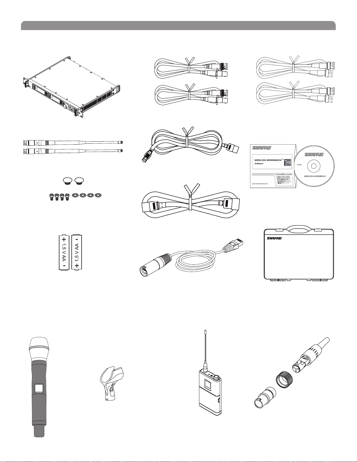
System Components
All systems include:
English
UR4S+ or UR4D+ Receiver
(UR4D+ pictured)
Two 1/2 Wave Antennas
2 Antenna hole plugs
4 Rack Mount Screws with Washers
AA Batteries
Two Antenna Cables
IEC Power Cable
IEC Power Extension Cable
Ethernet Network Cable with “Ruggedized” plug
Two RF Distribution Cables
Shure’s Wireless Workbench Software
Transmitter Carrying Case
Handheld Systems Include:
Microphone Head (choice of SM58®, SM86, Beta 58A®, Beta
87A™, Beta 87C™ or KSM9/BK, KSM9/SL)
UR2 handheld transmitter
Microphone clip
Bodypack Systems Include:
• UR1 Bodypack Transmitter
• Threaded TA4F Adapter
Threaded TA4F Adapter
UR1
7
Page 7
Shure UHF-R Wireless
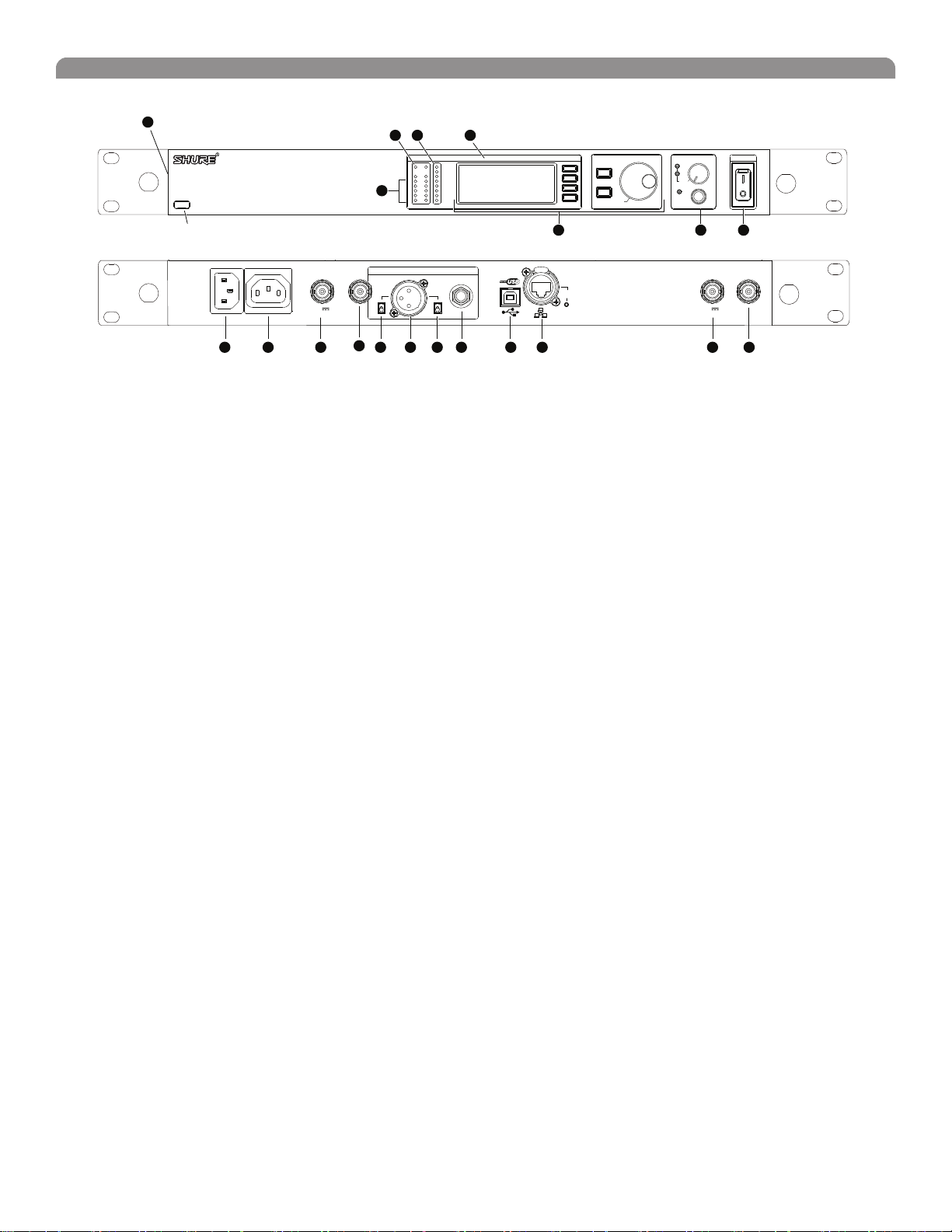
Receiver Controls and Connectors
18
17
UR4S+
Wireless Receiver
with Audio Reference Conpanding
sync
234 5
RF Audio
OL
A B
XX YYY-ZZZ MHz Navigate
6 7 8
ENTER
EXIT
OFF
push
Monitor Clip
Monitor
Control
push
POWER
antenna B in
RF B out
balanced low Z
12.7V out
150mA
10 11 1112 13 14 15 16 17 19
9
line
mic
19
SYNC Infrared (IR) port. Transmits group, channel, and other
settings to a transmitter. See page 15.
Squelch LEDs.
• Blue (On) = Transmitter signal detected
• Off = no signal or signal squelched because of poor reception
or no tonekey
NOTE: The receiver will not output audio unless at least one
blue LED is illuminated.
RF LEDs. Indicate RF signal strength from the transmitter at
each antenna and diversity condition.
• Amber = normal
• Red = overload (greater than –25 dBm)
4 Audio LEDs. Indicate audio signal strength from transmitter.
• Green = signal present
• Yellow = normal peak
• Red = overload
To correct this level, adjust the transmitter gain.
5 Indicates the name and range of receiver frequency band.
LCD Interface. Provides a convenient way to program the
receiver from the front panel (see detail on next page).
7 Monitor. 1/4” output jack and volume knob for headphones.
• Monitor Clip LED indicates headphone audio is clipping.
• Dual models: Push the knob to switch from receiver one to
receiver two.
receiver outputs
200Ω
lift
GND
networking
network
activity
ethernet
RJ-45
antenna A in
12.7V out
150mA
RF A out
Power switch. Powers the unit on and off.
AC mains power input, IEC connector. 100–240 Vac.
AC mains power passthrough (unswitched). Use IEC
extension cables to connect up to five UR4+ receivers to a
single AC power source.
Diversity antenna inputs A and B.
Note: Antenna inputs are DC biased. Use only antenna
combiners and accessories listed in page 19. Some types of
antenna splitters or other products may short the DC power
and damage the receiver.
Mic/Line switch. Changes output level 30 dB (XLR output only).
Electrically balanced XLR output jack
Lift/GND switch. Lifts ground from Pin 1 of the XLR connector
(default = GND).
Impedance balanced 1/4” output jack (200Ω)
USB jack for computer interface.
RJ-45 jack for Ethernet network interface. Accepts both regular
and “ruggedized” RJ-45 plugs.
Temperature-activated fan ensures top performance in high
temperature environments. Clean fan screen as needed to
remove dust.
The RF distribution ports pass the RF signal from one receiver to
the next, allowing a maximum of 10 receivers to share a single
pair of antennas.
Note: The diagram above represents the UR4S single channel receiver. The UR4D dual channel receiver is functionally identical to the UR4S, adding a
second LCD interface and set of output jacks for channel 2.
8
Page 8
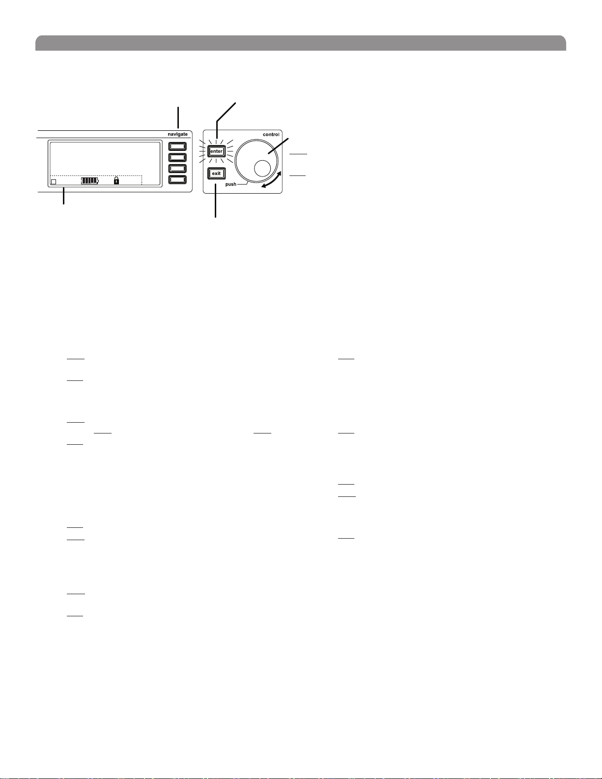
Receiver LCD Interface
Menu Access
Press the Navigate key next to the menu
item you want to select.
English
Accept Changes
After changing a parameter, the ENTER button flashes. Press
it to save the value.
F, P, FP
Radio
Audio
Util
Sync
SHURE
524-025 MHz TV: 32
G: 3 Ch: 1 Out: -0dB
+12 dB
+
Hi
Transmitter Status Display
Everything under the dotted line reflects the
settings for the transmitter, if present. (main
title screen only).
Exit/Cancel
Press the Exit button to cancel changes and
return to the previous menu.
Receiver Parameters
Use the following instructions to set parameters through the LCD interface.
NOTE: After adjusting a parameter, you must press the flashing ENTER button to accept the change.
Group and Channel
Menu: Radio
• Push the Control wheel to move the cursor to the Group (G)
or Channel (Ch) parameter.
• Turn the Control wheel to change the parameter.
Frequency
Menu: Radio
• Push the Control wheel to move the cursor to the integer
value (524.025 MHz) or fractional value (524.025).
• Turn the Control wheel to change the value.
Automatic Transmitter Sync
Menu: Sync
• See page 15.
Receiver Name
Menu: Util
• Turn the Control wheel to change the letter.
• Push the Control wheel to move to the next letter.
Output Level
Menu: Audio
This setting adjusts the signal level at the XLR and 1/4” audio output jacks.
• Turn the Control wheel to change the relative level in dB. (0
dB to –32 dB).
• Turn the wheel all the way down to mute the outputs.
Cursor Control
Push the Control wheel to move the
cursor to the next item.
Turn the Control wheel to change a
parameter value.
Squelch
Menu: Radio > Squelch
• Turn the Control wheel to change the parameter
Receiver Lock
When locked, the receiver settings cannot be changed from the front
panel. However, you can still navigate the LCD menu to view the settings
(and turn the lock off).
Menu: Util > Lock
• Turn the Control wheel to toggle the lock on or off (ON or
OFF).
LCD View
Menu: Util > Title
• Turn the Control wheel to mark an item for display.
• Push the Control wheel to move to the next item.
LCD Contrast
Menu: Util > Contrast
• Turn the Control wheel to increase or decrease contrast.
Tonekey
Menu: Radio > Squelch > Tonekey
Tonekey squelch mutes the outputs unless the receiver detects a
transmitter. Tonekey should be left on (On) except for certain
troubleshooting operations.
9
Page 9
Shure UHF-R Wireless
Network Parameters
NOTE:
• The receiver reboots after you press ENTER to accept network
parameter changes
• In dual models (UR4D+), these settings affect both receivers
(the dual receiver is treated as a single network device).
Set the Receiver Network Mode
Menu: Util > Network
1. Push the Control wheel to move the cursor to the Mode
parameter.
2. Turn the Control wheel to set the receiver to one of the
following values:
• DHCP: use this setting when connecting the receiver to a DHCP
server.
• Manual: allows you to set the receiver to a specific IP address
or subnet.
IP Address and Subnet
Menu: Util > Network
NOTE: To change these settings, the network mode
must be set to Manual.
1. Push the Control wheel to move the cursor to any of the
following parameters:
• IP (IP address)
• Sub (Subnet mask)
2. Turn the Control wheel to change the value.
Device ID
Assists in identifying receivers through the Wireless Workbench Software
(has no effect on network identification).
Menu: Util > Network
1. Push the Control wheel to move the cursor to the DevID
parameter.
2. Turn the Control wheel to set the receiver to change the value.
Custom Groups This feature allows you to create your own groups of
frequencies.
Creating new groups...
Menu: Radio > Custom
3. Turn the Control wheel to select a custom group number (U1,
U2, U3, etc.)
4. Push the Control wheel to move to the Channel parameter
and turn it to select a channel (01, 02, 03, etc.)
5. Push the Control wheel to move to the Freq parameter and
select a frequency for that channel.
6. Push the NEXT menu key to select a frequency for the next
channel in that group.
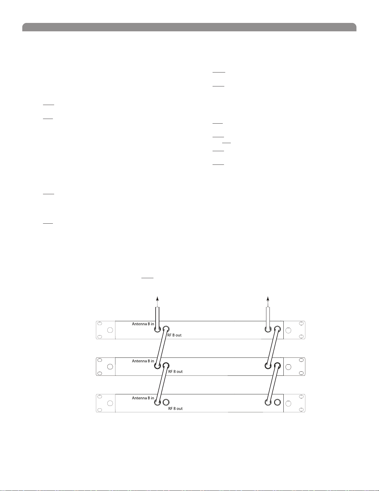
Connecting Multiple Receivers to the RF Distribution Ports
The RF distribution ports pass the RF signal from one receiver to the next, allowing a maximum of 10 single or dual receivers to share a single pair of
antennas.
Use the supplied RF distribution cables to connect the ports of each receiver as shown.
NOTE: All receivers must be operating in the same frequency band.
To Antenna ATo Antenna B
Antenna A in
First Receiver
Antenna A in
Additional Receivers
Antenna A in
Last Receiver
RF A out
RF A out
RF A out
10
Page 10

English
Automatic Frequency Selection
Follow these steps to use the channel scan and group scan features.
Before you begin...
• Install the receivers in the location where they will be used and power them on.
• Mute all inputs on mixing devices connected to receivers.
• Turn off all bodypack or handheld transmitters for the systems you are setting up.
• Turn on potential sources of interference such as other wireless systems or devices, computers, CD players, effects processors, and digital
rack equipment so they are operating as they would be during the presentation or performance.
Single Receiver
1. Select Radio > Scan > Chan Scan using the Navigate keys on the receiver LCD interface.
2. Turn the Control wheel to select a group.
3. Press Chan Scan. The display indicates that the receiver is searching. Once it has finished, it displays the selected channel.
4. Press the flashing ENTER button to accept the suggested channel.
5. Sync the transmitter (see page 15).
Networked or Dual Receivers
With networked or dual receivers, you can take advantage of the group scan feature to set group and channel settings for all the receivers at the same
time. (See page 12 for instructions on networking.)
Perform a group scan from any receiver...
1. Select Radio > Scan> Group Scan using the Navigate keys on the receiver LCD interface. The display indicates that the receiver is
searching (Scan In Progress). Once it has finished, it displays the group with the most open channels.
2. If you wish, turn the Control wheel to change groups. The number of open channels for each group is displayed.
3. Press the flashing ENTER button to set all receivers to open channels in that group.
NOTE: The group scan feature only works for receivers in the same frequency band. For example, if you did a group scan on a “H4” band
receiver, all “H4” band receivers would be set up, but not “J5” band receivers.
Multiple Receivers—Not Networked
If your receivers are not networked (or in different bands), the group scan cannot automatically set their group and channel settings. However, you can
still take advantage of the group scan feature to find the group with the most open channels and the channel scan feature to find open channels in that
group.
Find the group with the most open channels...
Perform a group scan using the steps for a networked receiver (above). However, make a note of the selected group before pressing the flashing ENTER
button to accept it.
Set the receivers to open channels in that group...
Perform a channel scan on the remaining receivers using the steps for a single receiver (above). Make sure to select the same group for each receiver
before performing the channel scan.
IMPORTANT: After setting the channel for the first receiver, immediately sync the transmitter for that receiver and leave it on so that the
next receiver detects that channel during its channel scan. Otherwise, all the receivers will be set to the same open channel.
NOTE: Receivers in different bands (H4, J5, L3, etc.) do not need to be set to the same group.
11
Page 11
Shure UHF-R Wireless
Ethernet
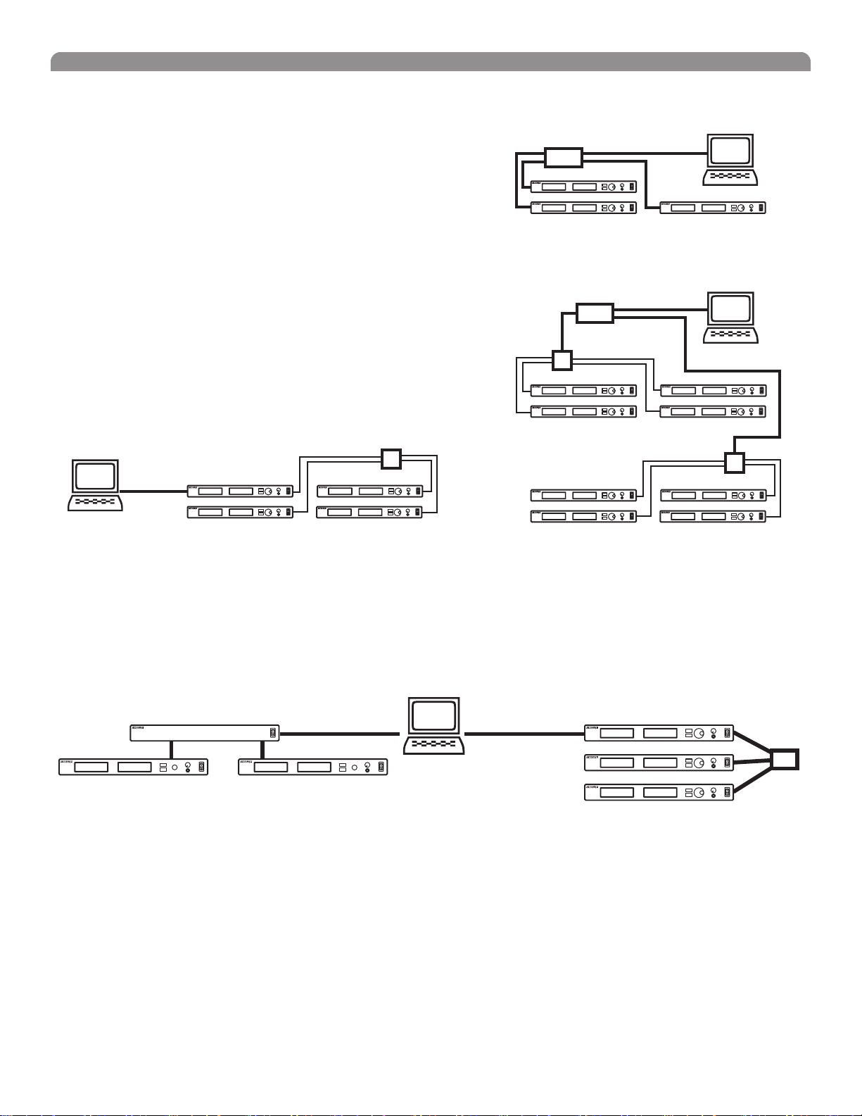
Networking Receivers
Basic Network
Connect receivers to an Ethernet router with DHCP service. Use Ethernet switches to
extend the network for larger installations.
Use the receiver’s default network setting
(Util > Network > Mode = DHCP).
Accessing the Network with a Computer
If you want to use the Wireless Workbench software, connect your computer to the
network and install the software from the CD that came with the receiver. Make sure
your computer is configured for DHCP (from Control Panel, click Network Connections.
Double-click on Local Area Connection. Select Internet Protocol (TCP/IP) and click
Properties. Select Obtain IP address automatically and Obtain DNS server address
automatically and click OK).
NOTE: Some security software or firewall settings on your computer can
prevent you from connecting to the receivers. If using firewall software, allow
connections on port 2201.
Using USB...
Connect the computer to the USB port on any of the receivers to access the whole
network.
Router with DHCP
Router with DHCP
Switch
Computer
(optional)
Computer
(optional)
Switch
USB
Static IP Addressing
The receiver also supports static IP addressing. Assign your own IP addresses ( Util > Network > Mode = Manual). See “Network
Parameters” on page 10.
NOTE: Dual receivers use a single IP address, which may be set through either LCD interface.
Existing UHF Network Installations
Both Shure’s UHF-R receivers and legacy UHF receivers can be networked to the same PC and accessed using the latest Wireless Workbench
software.
UHF
U888
USBRS-232
UHF-R
12
Page 12
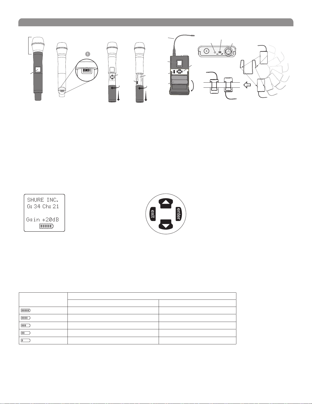
Handheld and Bodypack Transmitter Controls and Connectors
English
Interchangeable microphone head (BETA 87A pictured).
LCD Panel.
Power Switch.
Control buttons for LCD interface.
Infrared (IR) port. See page 15.
Transmitter LCD Interface
Up Arrow Key. Scroll up
or increase a value.
Battery compartment.
Flexible Antenna.
Power LED.
4-Pin Microphone Input Jack.
Reversible Belt Clip.
524.025 MHz
Main Menu
exit Key. Move to the left, or exit
without saving changes.
Down Arrow Key. Scroll
down or decrease a value.
enter Key. Press to select parameters
and accept the selected value.
Transmitter Batteries
Transmitters operate on standard AA batteries. Turn off the transmitter before changing the batteries.
The battery fuel gauge displayed on the transmitter LCD gives an indication of remaining battery life, as shown below.
UR1, UR2:
Transmitter Display Approximate Hours Remaining (alkaline batteries)
UR1/UR2 (Normal Power) UR1/UR2 (High Power*)
7.5 to 9.5 5 to 6
5.75 to 7.5 4 to 5
4 to 5.75 3 to 4
2 to 4 1.5 to 3
15 minutes to 2 hours 10 minutes to 1.5 hours
* High power setting not available with models sold in countries that prohibit its use.
13
Page 13

Shure UHF-R Wireless
taphold
Transmitter Parameters
Press ENTER from the main menu to access the following parameters:
Group (G) and Channel (Ch). Must match the receiver’s settings.
G:34 Ch:21
524.025MHZ
Gain +20dB
SHURE INC.
Use the following key combinations to access additional features and parameters:
Frequency (MHz). Manual frequency selection in 0.025 MHz increments.
Gain (Gain). Adjusts audio level from –10 dB to +20 dB
Sensitivity (Sens) (bodypack only).
Sets audio input to +15 dB, 0 dB, or –10 dB recommended for guitars.
Name Display. 12-digit ASCII.
LCD Panel
Changes LCD Panel
Lock Indicators
taphold
taphold
hold tap
Frequency Lock
Toggles setting. When enabled, frequency cannot be changed, and a transmitter sync will
not overwrite the frequency setting.
Power Lock
Toggles power lock. When locked, power switch does not turn off transmitter.
RF power level setting*
Use the arrow keys to select normal (10 mW) or high power (50/100 mW**). Use the normal power setting to conserve
batteries or prevent RF overload at the receiver.
* High power setting not available with models sold in countries that prohibit its use.
** High power value varies with model.
524.025MHZ
Power Lock
Frequency Lock
Setting Transmitter Gain
Adjust the transmitter gain and input sensitivity so that the Audio LEDs on the receiver peak within the yellow range during use. On the bodypack
transmitter, you can change the sensitivity setting to compensate for different audio levels when connecting different instruments or microphones to the
input.
To adjust gain, turn on the transmitter and press the enter button. Scroll down to the Gain parameter or the Sens parameter (bodypack only) and
press enter again. Use the arrow keys to adjust the setting and press enter to save it (Exit cancels without saving).
RF Safety Mode
This special feature temporarily mutes RF broadcast. This allows you to change frequency settings on a transmitter without accidentally “cutting in” on a
channel being used by another transmitter.
1. Turn the transmitter off.
2. Hold down exit key while turning on the transmitter power (for handheld microphones, you need to pull the battery cover off the handle). The
LCD flashes while the unit is in RF safety mode.
3. Change group and channel settings as you normally would—the transmitter will not broadcast.
4. Power the transmitter off and on to exit RF safety mode.
14
Page 14

English
Automatic Transmitter Sync
This feature automatically updates a bodypack or handheld transmitter’s group and channel settings to match those of a selected receiver.
To perform a transmitter sync...
1. Open the transmitter battery cover to display the infrared (IR) port.
2. With the IR port exposed to the receiver, select Sync > sync from the receiver LCD interface.
The display on the receiver indicates whether the sync was successful. If the sync fails, try again, making sure that the IR port on the transmitter is
exposed and directly faces the IR port on the receiver.
NOTE: Close the battery door before performing a sync on other transmitters.
®
Audio ABJ 779-810 MHz NavigateRF
OL OL
UR4D+
Wireless Receiver
with Audio Reference
Companding
sync
Audio ABJ 779-810 MHz NavigateRF
ENTER
EXIT
sync
Monitor
Control
Power
1
2
push
Monitor Clip
To transfer other transmitter settings...
Optionally, you can transfer other transmitter settings from a receiver when you perform a sync. Use the following steps:
1. Select Sync > Setup from the receiver LCD interface.
2. Turn the Control wheel to change parameter settings.
3. Push the Control wheel to move to the next parameter.
4. Push the flashing ENTER button to save the settings.
The transmitter settings you set on the receiver remain for future syncs.
NOTE: If you don’t want the sync to send a setting, set the parameter to No Change
Available Settings...
The following settings are available from the Sync > Setupmenu:
• Sensitivity (Sens) bodypack only
• Gain (Gain)
• RF Power (Pwr)
• Power and Frequency Lock (Lock), which has the following values:
Power lock only: (Pwr Only)
Frequency lock only: (Freq only)
Both: (Freq and Pwr)
Neither: (Unlocked)
• Custom Groups (CG):
On (ON): Send custom groups to transmitters during sync
Off (OFF): Do not send custom groups (reduces sync time)
15
Page 15

Shure UHF-R Wireless
Troubleshooting
Issue See Solution...
No sound
Faint Sound or Distortion
Lack of range, unwanted noise bursts, or drop outs
Cannot turn transmitter off or change frequency settings, or can’t program receiver
Excessive hum or buzzing
Power, Cables, or RF
Gain
RF
Interface Locks
Ground lift
Power
Make sure that the transmitter and receiver are receiving sufficient
voltage. The receiver requires at least 90 Vac. Check the battery indicator
on the transmitter and replace battery if necessary.
Gain
Adjust the transmitter gain and sensitivity settings (see page 14) or the
receiver output level (page 9), or toggle the mic/line switch on the back
of the receiver.
Cables
Check that all cables and connectors are in working order.
Ground Lift
Lifting the ground on pin 1 of the XLR output on the receiver can
sometimes remove hum or buzz in the audio signal. Set the GND/LIFT
switch on the receiver to LIFT if you are using the XLR connector.
Interface Locks
Both the transmitter and receiver can be locked to prevent accidental
changes. On transmitters, look for a lock symbol on the LCD and use the
key combinations illustrated on page 14 to turn it off.
To turn off the receiver interface lock, see page 9.
Increasing Range
If the transmitter is more than 6 to 60 m (20 to 200 ft) from the receiver
antenna, you may be able to increase range by doing one of the following:
• Reduce interference (see above)
• Increase transmitter RF power level (see page 14).
• Use an active directional antenna, antenna distribution system, or
other antenna accessory to increase RF range (see page 19).
Radio Frequency (RF)
Using the RF LEDs
If neither blue RF LED is illuminated, then the receiver is not detecting the
presence of a transmitter.
The amber RF LEDs indicate the amount of signal being received. This
signal could be from the transmitter, or it could be from an interfering
source, such as a television broadcast. Turn the transmitter off. If more
than one or two of the amber RF LEDs are still illuminated, then that
channel has too much interference, and you should try a different channel.
The red RF LED indicates RF overload. This will usually not cause a
problem unless you are using more than one system at the same time, in
which case, it can cause interference between systems.
Eliminating RF Overload
If you see the red RF LED on a receiver, reduce the transmitter RF
power level (see page 14) or move the transmitter further away from the
receiver—at least 6 m (20 ft). If you are using active antennas, reduce
antenna or amplifier gain.
Compatibility
• Perform a transmitter sync, or make sure the transmitter and
receiver are set to the same group and channel.
• Look at the label on the transmitter and receiver to make sure
they are in the same band (H4, J5, L3, etc...).
Reducing Interference
• Use a different channel or perform an automatic group or channel
scan (see page 11).
• For multiple systems, check that all systems are set to channels
in the same group (systems in different bands do not need to be
set to the same group).
• Maintain a line of sight between transmitter and receiver
antennas
• Move receiver antennas away from metal objects or other
sources of RF interference (such as CD players, computers,
digital effects, network switches, network cables and Personal
Stereo Monitor (PSM) wireless systems).
• Eliminate RF overload.
16
Page 16

SPECIFICATIONS
Band Range Transmitter power
Handheld UR2 BodyPack UR1
G1
G1E
H4
H4E
J5
J5E
K4E
L3
L3E
M5E
Q5
R9
Q6
A24
JBX
Q10A
R16
R18
X1
This Radio equipment is intended for use in musical professional entertainment
This Radio apparatus may be capable of operating on some frequencies not
authorized in your region. Please contact your national authority to obtain
information on authorized frequencies and RF power levels for wireless
RF Carrier Frequency Range
470-865, 944-952 MHz depending on region
Working Range
UR1, UR2
150 m (500 ft.), under typical conditions
500 m (1600 ft) line-of-sight, outdoors for a single system.
NOTE: Actual working range depends on RF signal absorption, reflection
and interference.
Audio Frequency Response
40 – 18,000 Hz, (+1 dB, –3 dB).
NOTE: Overall system frequency response depends on the microphone
element
Gain Adjustment Range
UR1: –20 to +35 dB
–10 dB recommended for guitar
UR2: –10 to +20 dB
Modulation
FM (45 kHz max. deviation), compander system with pre- and de-emphasis
RF Power Output
See table above.
Dynamic Range
>105 dB, A-weighted
Image Rejection
>110 dB typical
RF Sensitivity
470-530 MHz 10 / 50 10 / 100
470-530 MHz 10 / 50 10 / 50
518-578 MHz 10 / 50 10 / 100
518-578 MHz 10 / 50 10 / 50
578-608, 614-638 MHz 10 / 50 10 / 100
578-638 MHz 10 / 50 10 / 50
606-666 MHz 10 / 50 10 / 50
638-698 MHz 10 / 50 10 / 100
638-698 MHz 10 / 50 10 / 50
694-758 MHz 10 / 50 10 / 50
740-814 MHz 10 / 50 10 / 50
790-865 MHz 10 / 50 10 / 50
740-752 MHz 10 10
779-788 / 797-806 MHz 10 10
806-810 MHz 10 10
740-787 MHz 10 / 50 10 / 50
794-806 MHz 10 / 50 10 / 50
794-806 MHz 10 only 10 only
944-952 MHz 10 / 50 10 / 100
NOTE
and similar applications.
microphone products
UR4S+ UR4D+
–110 dBm Typical
12 dB SINAD
–105 dBm Typical
30 dB SINAD
–107 dBm Typical
12 dB SINAD
–102 dBm Typical
30 dB SINAD
(Nominal mW)
.
English
Spurious Rejection
>90 dB typical
Ultimate Quieting (ref. 45 kHz deviation)
>100 dB, A-weighted
Signal Polarity
Positive pressure on microphone diaphragm (or positive voltage applied to
tip of WA302 phone plug) produces positive voltage on XLR output pin 2
with respect to XLR pin 3 and on the tip of the 1/4-inch output jack.
System Distortion (ref. ± 45 kHz deviation, 1 kHz modulation)
<0.3% Total Harmonic Distortion typical
Power Requirements
UR1, UR2: Two 1.5V AA batteries
UR4+:100 to 240 VAC, 50/60 Hz
Current Drain
UR1, UR2: 180 mA max. (normal RF power setting)
240 mA max. (high RF power setting)
UR4D+, UR4S+: 0.8 Amps max.
Battery Life (Typical)
UR1, UR2: 9.5 hours (normal RF power),
6 hours (high RF power)
Operating Temperature Range
–18° to +57° C (0° to +135°F)
NOTE: Battery characteristics may limit this range
NOTE: Electrical safety approval is based on a maximum ambient
temperature of 35°C (95°F).
Overall Dimensions
UR1: 98 mm L x 60 mm W x 17 mm D (3.84 x 2.38 x 0.66 in.)
UR2/SM58: 261 mm L x 51 mm Dia. (10.27 x 2 in.)
UR2/SM86: 261 mm L x 51 mm Dia. (10.27 x 2 in.)
UR2/SM87A: 254 mm x 51 mm Dia. (10 x 2 in.)
UR2/KSM9/BK, UR2/KSM9/SL: 250 mm x 49 mm Dia. (9 7/8 x 1 15/16 in.)
UR2/BETA 58: 258 mm L x 51 mm Dia. (10.15 x 2 in.)
UR2/BETA 87A, UR2/BETA 87C: 254 mm x 51 mm Dia. (10 x 2 in.)
UR4S+/UR4D+: 44 mm H x 483 mm W x 366 mm D
(1.72 x 19.00 x 14.39 in.)
Net Weight
UR1: 97 g (3.4 oz.) without batteries
UR2/SM58: 356 g (12.6 oz.) without batteries
UR2/BETA 58: 314 g (11.1oz.) without batteries
UR2/SM86: 317 g (11.2 oz.) without batteries
UR2/SM87A: 298 g (10.5 oz.) without batteries
UR2/KSM9/BK, UR2/KSM9/SL: 410 g (14.5 oz.) without batteries
UR2/BETA 87A, U2/BETA 87C: 325 g (11.5 oz) without batteries
UR4S+: 5.0 kg (10.9 lbs)
UR4D+: 5.1 kg (11.2 lbs)
Housing:
UR1: Cast magnesium
UR2: Aluminum die-cast handle and aluminum machined battery cup
UR4S+, UR4D+: Galvanized steel
Wiring for TA4F:
MICROPHONE
ELEMENT
NOTE: LAVALIER MIC TIES PINS 3 AND 4 TOGETHER—GUITAR CABLE DOES NOT.
TA4F
Connector
TA4M
Connector
UR1 MIC JACK BOARD
Active Load
Audio
Ground
17
Page 17

Shure UHF-R Wireless
Inputs and Outputs
UR1 Transmitter Audio Input
Connector: 4-Pin male mini connector (TA4M)
Input Configuration: Unbalanced, active
Maximum Input Level:
(1 kHz, 1% THD)
TA4M Connector Pin
Assignments:
UR2 Transmitter Audio Input
Input Configuration: Unbalanced, active
Actual Impedance: >1 MΩ
Maximum Input Level:
1 kHz, 1% THD
UR1 Transmitter RF Output
Connector: SMA
Actual Impedance: 50 Ω
Pin Assignments: Shell = Ground
RF Distribution Ports
Connector Type BNC BNC
Vdc Bias 12 Vdc @ 150 mA N/A
+10 dBu (sensitivity 0 dB)
+20 dBu (sensitivity –10 dB)
Pin 1: Ground
Pin 2: +5 Vdc bias
Pin 3: Audio, 200 kΩ
Pin 4: Tied through active load (on main board)
to Ground.
(On instrument adapter cable, Pin 4 floats)
+4.8 dBu
Center = Signal
RF IN RF OUT
Receiver Input
Antenna Power
Connector Type: BNC IEC
Actual Impedance:
Nominal Input Level: –95 to –30 dBm 100-240 VAC, 50/60 Hz
Maximum Input Level: –20 dBm 240 VAC, + 10%,
Pin Assignments: Shell = Ground
Bias Voltage* 12 Vdc @ 150 mA
* For remote antenna amplifiers
Ω
50
Center = Signal
maximum
-
50/60 Hz
IEC Standard
N/A
Receiver Audio Output
Monitor (1/4”
1/4” Phone XLR
Headphone)
Output
Configuration:
Actual Impedance:
Unbalanced
mono, 1/4 inch
Impedance
Balanced
Electrically
Balanced
50 Ω 200 Ω 200 Ω (active
balanced)
(150 Ω mic)
Maximum
Output Level:
1 Watt @ 63 Ω +18 dBu +24 dBu
(–6 dBu mic)
with 100 Hz
modulating tone
Pin Assignments:
Phantom Power
Protection:
Tip = Hot
Ring = Hot
Sleeve = Gnd
Tip = Hot
Ring = no signal
Sleeve = Gnd
1 = Ground
2 = Audio +
3 = Audio –
No Yes Yes
Computer/Network Interface
Ethernet USB*
RJ45 USB Series B Receptacle
* USB-IF logo is a trademark of Universal Serial Bus Implementers Forum, Inc.
XLR
1/4" Monitor/headphone
1/4" Phone
18
Page 18

Replacement Parts and Accessories
Furnished Accessories
Microphone Stand Adapter (UR2)
Threaded locking Adapter (with TA4F), UR1
Zipper Bag (UR1)
Zipper Bag (UR2)
Antenna Extension Cables (2)
RF Distribution Cables (2)
Antenna (UR1) 470-530 MHz
Antenna (UR1) 518-578 MHz
Antenna (UR1) 578-698 MHz
Antenna (UR1) 740-865 MHz
Antenna (UR1) 944-952 MHz
Two Antennas (UR4+), Band Dependent (see table)
Transmitter Carrying Case
Optional Accessories
SM58 Head with Grille
SM86 Head with Grille
BETA 58 Head with Grille
BETA 87A Head with Grille
BETA 87C Head with Grille
SM87A Head with Grille
KSM9/SL Head with Grille
KSM9/BK Head with Grille
Matte Silver Grille (SM58)
Matte Silver Grille (SM86)
Matte Silver Grille (BETA 58)
Black Grille (SM87)
Matte Silver Grille (BETA 87A)
Matte Silver Grille (BETA 87C)
Black Grille (BETA 58)
Black Grille (BETA 87A/BETA 87C)
Champagne Grille (KSM9/SL)
Black Grille (KSM9/BK)
Popper Stopper‘ Windscreen
Belt Clip (UR1)
Bodypack Pouch (Black), UR1
Bodypack Pouch (White), UR1
WA371
WA340
26A13
26A14
95B9023
95N2035
UA700
UA710
UA720
UA730
UA740
UA820
95C9053
RPW112
RPW114
RPW118
RPW120
RPW122
RPW116
RPW180
RPW184
RK143G
RPM266
RK265G
RK214G
RK312
RK312
RK323G
RK324G
RPM260
RPM264
A85WS
44A8031
WA580B
WA580W
English
Antenna Combiners and Accessories
• Antennas and receivers must be from the same frequency band.
• The supplied 1/2 wave antennas can be remotely mounted or
mounted directly to the UA845.
• Antennas and cables for use with the UA845 can also be used
with stand-alone UHF-R receivers.
Passive Antenna/Splitter Combiner Kit
(recommended for 2 receivers)
UHF Antenna Power Distribution Amplifier
U.S.A. (470-952 MHz)
Europe
UK
1/2 Wave, Omnidirectional,
Wideband Antenna (470-952 MHz)
Active Directional Wideband Antenna
(470-698 MHz)
Active Directional Narrowband Antenna
(944-952 MHz)
Wideband In-Line RF Amplifier (470-698 MHz)
Narrowband In-Line RF Amplifier (944-952 MHz) UA830X
Passive Unidirectional Wideband Antenna
(470-952 MHz)
Passive Unidirectional Narrow band Antenna
(944-952 MHz)
1/2 wave antennas (2)
G1 Band
H4E, H4 Bands
J5E, J5 Bands
L3E, L3 Bands
Q5, Q6, Q10A Bands
R9, ABJ Bands
X1 Band
10’ Antenna Cable
25’ Antenna Cable (RG-8/X)
50’ Antenna Cable (RG-8/X)
100’ Antenna Cable
UA221
UA845UA845SWB
UA845E
UA845UK
UA860SWB
UA870USTV
UA870X
UA830USTV
PA805SWB
PA805X
UA820G
UA820H4
UA820J
UA820L3
UA820Q
UA820A
UA820X
PA725
UA825
UA850
UA8100
Architects' and Engineers' Specifications
The wireless system shall operate in the UHF band between 470-865 MHz and 944-952 MHz, with the specific range being dependent on the user's
locale. The system shall include the option of changing the operating frequency in order to avoid RF interference, enabling up to 160 systems to operate
simultaneously in the same location. Preconfigured group, channel and frequency setups shall be available to ensure that multiple systems in use do not
interfere with one another.
All transmitters shall be powered by 2 AA batteries and shall have a power on/off switch. The bodypack will have an LED indicating that power is on.
Available transmitters shall include: a body pack for use with electric guitars, basses, and other electric instruments, and a handheld microphone for
vocals. The transmitters shall have a DC/DC converter to ensure consistent performance, even if battery voltages change.
The receiver shall have a user-programmable, menu-driven LCD showing group, channel, frequency, name, squelch level, and locked/unlocked status.
The system shall use technology such as MARCAD‚ signal combining circuitry to improve reception, minimize signal dropouts, and achieve the best
possible signal-to-noise ratio. An equalizer, tone key squelch, and noise squelch circuitry shall be built into the system to provide optimal sound quality
and minimize unwanted noise. The receiver shall include dual RF meters (one for each antenna), an audio level meter, and a Networking Interface
connector for computer control and monitoring. The receiver shall have a volume control and an adjustable noise squelch control.
The system shall be the Shure UHF-R Wireless.
19
Page 19

Shure UHF-R Wireless
CERTIFICATION
UR1, UR2, UR4S+, UR4D+
This Class B digital apparatus complies with Canadian ICES-003.
Cet appareil numérique de la classe B est conforme à la norme NMB-003 du Canada.
Meets requirements of EMC standards EN 300 422 Parts 1 and 2 and EN 301 489 Parts 1 and 9.
Meets essential requirements of European R&TTE Directive 99/5/EC, eligible to bear the CE mark.
UR1, UR2
Certified under FCC Part 74. (FCC ID: DD4UR1, DD4UR2). Certified by IC in Canada under RSS-123 and RSS-102. (IC: 616A-UR1, 616A-UR2).
Emission Designator: 120KF3E
UR4S+, UR4D+
Approved under the Declaration of Conformity (DoC) provision of FCC Part 15. Certified in Canada by IC to RSS-123. (IC: 616A-UR4P).
Conforms to Australian EMC requirements and is eligible for C-Tick marking.
Have been granted the following Country Safety Approvals:
cULus Mark for US and Canada: Meets UL6500 and CSA/CAN E60065. UL GS-Certified to EN60065.
Operation of this device is subject to the following two conditions: (1) this device may not cause interference, and (2) this device must accept any inter-
ference, including interference that may cause undesired operation of the device.
The CE Declaration of Conformity can be obtained from Shure Incorporated or any of its European representatives. For contact information please visit
www.shure.com
The CE Declaration of Conformity can be obtained from: www.shure.com/europe/compliance
Authorized European representative:
Shure Europe GmbH
Headquarters Europe, Middle East & Africa
Department: EMEA Approval
Wannenacker Str. 28
D-74078 Heilbronn, Germany
Phone: +49 7131 72 14 0
Fax: +49 7131 72 14 14
Email: EMEAsupport@shure.de
LICENSING INFORMATION
Licensing: A ministerial license to operate this equipment may be required in certain areas. Consult your national authority for possible requirements.
Changes or modifications not expressly approved by Shure Incorporated could void your authority to operate the equipment. Licensing of Shure wireless
microphone equipment is the user’s responsibility, and licensability depends on the user’s classification and application, and on the selected frequency.
Shure strongly urges the user to contact the appropriate telecommunications authority concerning proper licensing, and before choosing and ordering
frequencies.
INFORMATION TO USER
This equipment has been tested and found to comply with the limits for a Class B digital device, pursuant to Part 15 of the FCC Rules. These limits are
designed to provide reasonable protection against harmful interference in a residential installation. This equipment generates, uses and can radiate radio
frequency energy and, if not installed and used in accordance with the instructions, may cause harmful interference to radio communications. However,
there is no guarantee that interference will not occur in a particular installation. If this equipment does cause harmful interference to radio or television
reception, which can be determined by turning the equipment off and on, the user is encouraged to try to correct the interference by one or more of the
following measures:
• Relocate the receiving antenna.
• Increase the separation between the equipment and receiver.
• Connect the equipment into an outlet on a circuit different from that to which the receiver is connected.
• Consult the dealer.
Note: EMC conformance testing is based on the use of supplied and recommended cable types. The use of other cable types may degrade EMC
performance.
Changes or modifications not expressly approved by the manufacturer could void the user’s authority to operate the equipment.
20
Page 20

FREQUENCY BANDS G1, H4, H4E, J5, J5E, K4E, L3, L3E, M5E, Q5, R9, A24, JBX, Q6, Q10A, R16, AND R18
SYSTÈMES COMPATIBLES EN FRéQUENCE DANS LA BANDES G1, H4, H4E, J5, J5E, K4E, L3, L3E, M5E, Q5, Q9. R9, A24, JBX, Q6, Q10, R16 ET R18
FREQUENZKOMPATIBLE SYSTEME IM FREQUENZBEREICH G1, H4, H4E, J5, J5E, K4E, L3, L3E, M5E, Q5, Q9. R9, A24, JBX, Q6, Q10, R16 UND R18
SISTEMAS CON FRECUENCIAS COMPATIBLES EN LAS BANDAS G1, H4, H4E, J5, J5E, K4E, L3, L3E, M5E, Q5, Q9, R9, A24, JBX, Q6, Q10, R16 Y R18
SISTEMI COMPATIBILI IN FREQUENZA NELLA BANDAS G1, H4, H4E, J5, J5E, K4E, L3, L3E, M5E, Q5, Q9, R9, A24, JBX, Q6, Q10, R16 E R18
SISTEMAS COM FREQÜÊNCIAS COMPATÍVEIS DA NA FAIXA G1, H4, H4E, J5, J5E, K4E, L3, L3E, M5E, Q5, Q9, R9, A24, JBX, Q6, Q10, R16 E R18
H4 FREQUENCY BAND (518.000 - 578.000 MHz)
Channel
1
2
3
4
5
6
7
8
9
10
11
12
13
14
15
16
17
18
19
20
21
22
23
24
25
26
27
28
29
30
31
32
33
34
35
36
37
38
39
40
TV
22 & 27
TV
23 & 28
TV
24 & 29
TV
25 & 30
TV
26 & 31
All Bands All Bands Full
Spectrum
Full
Spectrum
Full
Spectrum
Group 1 Group 2 Group 3 Group 4 Group 5 Group 6 Group 7 Group 8 Group 9 Group 10
518.350 524.350 530.350 536.350 542.350 519.000 519.250 518.100 518.900 518.050
518.850 524.850 530.850 536.850 542.850 519.425 521.625 518.825 519.625 518.550
519.575 525.575 531.575 537.575 543.575 522.100 525.800 519.350 520.150 519.500
520.500 526.500 532.500 538.500 544.500 524.525 526.375 520.375 521.175 519.900
521.625 527.625 533.625 539.625 545.625 525.525 528.075 521.725 522.525 520.750
522.450 528.450 534.450 540.450 546.450 526.075 533.950 522.350 523.150 523.750
523.075 529.075 535.075 541.075 547.075 527.325 535.500 525.150 525.950 530.500
523.475 529.475 535.475 541.475 547.475 528.100 538.350 530.250 531.050 532.600
548.125 554.125 560.125 566.125 572.125 537.475 542.400 530.675 531.475 534.150
548.650 554.650 560.650 566.650 572.650 540.450 543.475 532.750 533.550 538.925
549.675 555.675 561.675 567.675 573.675 541.600 547.350 534.625 535.425 541.750
551.025 557.025 563.025 569.025 575.025 544.925 553.625 543.475 544.275 545.500
551.750 557.750 563.750 569.750 575.750 551.625 561.075 544.700 545.500 546.425
552.150 558.150 564.150 570.150 576.150 553.300 565.700 547.325 548.125 547.875
552.975 558.975 564.975 570.975 576.975 555.300 569.050 548.775 549.575 550.500
553.600 559.600 565.600 571.600 577.600 557.075 570.775 549.700 550.500 551.725
561.100 571.550 553.450 554.250 560.575
566.000 572.800 556.275 557.075 562.450
567.550 573.425 561.050 561.850 564.525
574.475 573.825 562.600 563.400 564.950
518.350 519.875 564.700 565.500 570.050
544.325 520.275 571.450 572.250 572.850
548.550 522.425 574.450 575.250 573.475
554.050 546.925 575.300 576.100 574.825
559.900 555.750 575.700 576.500 575.850
520.125 521.050 576.650 577.450 576.375
535.025 536.475 577.150 577.950 577.100
550.450 537.250 523.850 524.650 522.450
573.625 539.250 548.300 549.100 546.900
575.850 544.000 572.750 573.550 571.350
522.650 548.950 529.350 530.150 524.425
531.375 552.050 533.950 534.750 528.625
538.475 561.975 537.925 538.725 529.675
539.100 566.200 561.950 562.750 533.250
554.450 567.125 565.525 566.325 557.275
564.775 575.050 566.575 567.375 561.250
570.775 571.575 565.850
535.750 536.550 525.775
551.700 552.500 543.500
569.425 570.225 559.450
69
Page 21

J5 FREQUENCY BAND (578.000 - 607.975 - 614.025 - 638.000 MHz)
Channel
1
2
3
4
5
6
7
8
9
10
11
12
13
14
15
16
17
18
19
20
21
22
23
24
25
26
27
28
29
30
31
32
33
34
35
36
37
38
39
40
TV
32 & 37
Group 1 Group 2 Group 3 Group 4 Group 5 Group 6 Group 7 Group 8 Group 9 Group 10
TV
33 & 38
TV
34 & 39
TV
35 & 40
TV
36 & 41
All Bands All Bands Full
Spectrum
Full
Spectrum
Full
Spectrum
578.350 584.350 590.350 596.350 602.350 578.625 581.650 578.375 578.125 578.100
578.850 584.850 590.850 596.850 602.850 579.125 586.625 579.400 578.550 579.125
579.575 585.575 591.575 597.575 603.575 584.825 588.025 581.750 579.200 581.475
580.500 586.500 592.500 598.500 604.500 586.475 592.275 582.625 580.600 582.350
581.625 587.625 593.625 599.625 605.625 587.750 595.225 584.675 581.150 584.400
582.450 588.450 594.450 600.450 606.450 588.500 597.675 587.350 584.500 587.075
583.075 589.075 595.075 601.075 607.075 592.950 601.750 588.825 585.375 588.550
583.475 589.475 595.475 601.475 607.475 598.975 602.175 589.225 588.950 588.950
614.125 620.125 626.125 632.125 599.875 604.300 594.200 591.175 593.925
614.650 620.650 626.650 632.650 615.900 607.675 594.725 593.925 594.450
615.675 621.675 627.675 633.675 617.600 614.425 596.975 595.225 596.700
617.025 623.025 629.025 635.025 618.400 620.650 603.475 604.150 603.200
617.750 623.750 629.750 635.750 621.350 622.025 606.050 604.875 605.775
618.150 624.150 630.150 636.150 621.750 623.800 607.725 606.275 607.450
618.975 624.975 630.975 636.975 627.925 625.000 616.200 618.025 615.925
619.600 625.600 631.600 637.600 629.975 630.175 619.250 620.825 618.975
631.025 632.250 620.600 621.975 620.325
633.175 633.750 622.525 625.325 622.250
635.050 636.275 628.650 627.250 628.375
636.650 637.075 630.200 630.500 629.925
585.400 587.450 631.175 632.325 630.900
587.300 598.975 632.375 633.100 632.100
602.025 627.775 632.875 635.275 632.600
616.425 632.825 635.825 636.175 635.550
619.975 637.575 636.900 636.700 636.625
591.225 583.175 637.625 637.700 637.350
603.075 588.950 581.200 582.425 580.925
605.650 590.825 586.450 587.650 586.175
628.625 596.900 592.725 588.050 592.450
631.700 599.425 597.900 598.350 597.625
580.225 600.700 598.600 599.575 598.325
592.500 614.975 604.000 600.600 603.725
601.575 616.700 605.350 603.700 605.075
606.075 619.525 614.450 607.075 614.175
607.575 623.050 615.600 614.925 615.325
633.650 635.775 617.150 615.600 616.875
620.175 617.025 619.900
621.725 619.900 621.450
623.850 622.500 623.575
634.225 631.150 633.950
70
Page 22

L3 FREQUENCY BAND (638.000 - 697.875 MHz)
TV
Channel
1 638.350 644.350 650.350 656.350 662.350 643.775 649.800 638.100 638.900 638.050
2 638.850 644.850 650.850 656.850 662.850 644.375 650.800 638.825 639.625 638.550
3 639.575 645.575 651.575 657.575 663.575 651.900 653.000 639.350 640.150 639.500
4 640.500 646.500 652.500 658.500 664.500 654.150 659.550 640.375 641.175 639.900
5 641.625 647.625 653.625 659.625 665.625 660.375 660.775 641.725 642.525 640.750
6 642.450 648.450 654.450 660.450 666.450 661.125 661.350 642.350 643.150 643.750
7 643.075 649.075 655.075 661.075 667.075 662.875 665.425 645.150 645.950 650.500
8 643.475 649.475 655.475 661.475 667.475 664.300 668.050 650.250 651.050 652.600
9 668.125 674.125 680.125 686.125 692.125 667.125 675.575 650.675 651.475 654.150
10 668.650 674.650 680.650 686.650 692.650 669.500 679.750 652.750 653.550 658.925
11 669.675 675.675 681.675 687.675 693.675 679.000 683.450 654.625 655.425 661.750
12 671.025 677.025 683.025 689.025 695.025 683.525 684.875 663.475 664.275 665.500
13 671.750 677.750 683.750 689.750 695.750 688.825 686.800 664.700 665.500 666.425
14 672.150 678.150 684.150 690.150 696.150 689.750 691.750 667.325 668.125 667.875
15 672.975 678.975 684.975 690.975 696.975 690.425 692.300 668.775 669.575 670.500
16 673.600 679.600 685.600 691.600 697.600 691.500 693.050 669.700 670.500 671.725
17 693.525 693.500 673.450 674.250 680.575
18 694.725 695.550 676.275 677.075 682.450
19 697.075 696.200 681.050 681.850 684.525
20 697.575 697.100 682.600 683.400 684.950
21 649.125 645.875 684.700 685.500 690.050
22 658.825 658.800 691.450 692.250 692.850
23 662.200 663.675 694.450 695.250 693.475
24 677.025 664.800 695.300 696.100 694.825
25 682.675 678.400 695.700 696.500 695.850
26 650.050 646.825 696.650 697.450 696.375
27 651.450 648.050 697.150 697.950 697.100
28 671.075 651.275 643.850 644.650 642.450
29 677.600 657.075 668.300 669.100 666.900
30 695.200 662.350 692.750 693.550 691.350
31 647.450 674.950 649.350 650.150 644.425
32 648.400 679.350 653.950 654.750 648.625
33 666.000 680.750 657.925 658.725 649.675
34 675.900 682.500 681.950 682.750 653.250
35 679.525 685.450 685.525 686.325 677.275
36 696.250 689.700 686.575 687.375 681.250
37 690.775 691.575 685.850
38 655.750 656.550 645.775
39 671.700 672.500 663.500
40 689.425 690.225 679.450
42 & 47
Group 1 Group 2 Group 3 Group 4 Group 5 Group 6 Group 7 Group 8 Group 9 Group 10
TV
43 & 48
TV
44 & 49
TV
45 & 50
TV
46 & 51
All Bands All Bands Full
Spectrum
Full
Spectrum
Spectrum
Full
71
Page 23

H4E FREQUENCY BAND (518.000 - 578.000 MHz)
Channel
Full Range
max. #
of comp.
frequencies
(option 1)
Full Range
max. #
of comp.
frequencies
(option 2)
France
preferred:
User Group
A
(option 1)
France
preferred:
User Group
A
(option 2)
France
preferred:
User Group
B
(option 1)
France
preferred:
User Group
B
(option 2)
France
preferred:
User Group
C
(option 1)
France
preferred:
User Group
C
(option 2)
All Bands All Bands
Group 1 Group 2 Group 3 Group 4 Group 5 Group 6 Group 7 Group 8 Group 9 Group 10
1 518.100 518.900 518.750 518.750 518.100 518.500 520.225 518.300 518.500 518.575
2 518.825 519.625 519.500 519.500 521.500 520.025 522.025 519.000 522.250 520.300
3 519.350 520.150 521.250 520.500 522.975 522.225 522.775 522.025 523.675 521.750
4 520.375 521.175 523.250 521.750 525.700 522.975 525.900 524.000 524.500 522.300
5 521.725 522.525 524.250 523.250 532.500 524.900 526.300 530.025 526.350 526.350
6 522.350 523.150 527.500 526.750 532.900 530.225 533.500 532.700 528.000 527.525
7 525.150 525.950 535.250 527.250 534.500 536.775 535.000 533.500 528.500 527.975
8 530.250 531.050 536.500 531.500 538.975 540.900 536.225 533.900 531.900 531.800
9 530.675 531.475 543.750 537.250 544.775 545.500 541.500 542.300 535.075 535.400
10 532.750 533.550 547.750 547.500 546.975 549.300 550.300 546.775 542.700 536.275
11 534.625 535.425 548.250 550.750 550.100 550.500 557.100 549.900 543.425 540.975
12 543.475 544.275 550.750 554.500 561.500 556.500 560.975 560.225 552.550 547.975
13 544.700 545.500 552.500 562.500 565.300 556.900 562.775 560.975 553.725 551.225
14 547.325 548.125 561.750 563.500 565.700 568.025 568.225 568.225 565.425 551.950
15 548.775 549.575 567.500 569.250 568.025 570.975 570.775 570.775 566.025 552.950
16 549.700 550.500 571.250 571.750 572.500 572.900 572.000 572.700 568.125 557.250
17 553.450 554.250 574.750 572.250 574.100 573.700 572.700 573.100 571.675 558.400
18 556.275 557.075 575.750 575.750 576.025 576.025 574.300 574.300 572.150 558.800
19 561.050 561.850 577.250 576.500 577.500 577.500 576.975 576.975 573.675 561.800
20 562.600 563.400 577.750 577.750 520.775 518.100 520.975 520.975 576.650 568.375
21 564.700 565.500 520.500 528.500 534.100 525.300 525.100 528.225 536.075 525.650
22 571.450 572.250 521.750 529.250 538.225 528.775 536.975 540.700 556.975 553.600
23 574.450 575.250 530.500 530.500 540.900 533.300 540.000 544.225 560.575 567.575
24 575.300 576.100 531.250 538.500 541.700 533.700 542.300 550.300 519.125 523.575
25 575.700 576.500 534.750 540.250 546.225 546.225 556.000 556.000 521.700 533.050
26 576.650 577.450 537.250 543.750 549.700 549.700 556.700 556.700 539.550 556.700
27 577.150 577.950 540.250 544.500 552.025 552.025 557.900 557.100 554.600 566.125
28 523.850 524.650 546.500 545.750 560.775 554.975 566.300 557.900 558.050 572.000
29 548.300 549.100 551.500 551.500 564.500 565.700 575.000 562.775 539.025 518.050
30 572.750 573.550 554.500 552.500 566.500 568.775 576.225 566.300 540.725 536.675
31 529.350 530.150 555.500 556.250 573.700 572.500 545.100 538.375
32 533.950 534.750 560.500 558.750 556.125 571.175
33
537.925 538.725 563.500 559.750 557.400 573.100
34 561.950 562.750 564.250 567.500 570.000 575.250
35 565.525 566.325 569.250 568.500
36 566.575 567.375 570.500 569.750
37 570.775 571.575
38 535.750 536.550
39 551.700 552.500
40 569.425 570.225
72
Page 24

J5E FREQUENCY BAND (578.000 - 638.000 MHz)
Full Range
max. #
Channel
1 578.375 578.375 578.500 578.500 578.225 578.225 578.775 580.000 589.375 581.050
2 579.400 579.100 579.250 579.250 578.975 578.975 580.000 580.700 590.525 582.400
3 581.750 580.175 579.750 582.750 580.900 580.900 582.300 581.100 591.175 583.950
4 582.625 583.125 583.250 583.250 582.500 581.300 583.000 581.900 595.300 584.950
5 584.675 583.625 585.750 585.750 585.500 582.500 584.975 584.975 596.350 585.700
6 587.350 584.825 587.500 591.750 593.500 586.975 589.100 591.000 600.375 589.250
7 588.825 585.800 593.250 593.250 594.975 592.025 592.225 594.775 601.875 589.900
8 589.225 587.350 595.500 595.500 597.300 598.500 597.100 597.500 602.825 591.125
9 594.200 593.475 598.750 604.250 604.900 606.100 597.900 605.900 604.925 593.350
10 594.725 595.400 610.500 607.500 605.700 608.775 605.500 606.300 605.700 599.100
11 596.975 596.750 611.250 608.500 606.100 609.500 608.975 608.225 616.900 610.300
12 603.475 599.800 615.500 609.250 610.975 610.975 610.775 610.775 622.650 611.075
13 606.050 608.275 623.250 617.750 624.775 620.900 621.500 621.100 624.875 613.175
14 607.725 609.950 623.750 623.250 626.975 624.775 623.000 624.975 626.100 614.125
15 616.200 612.525 625.750 623.750 628.900 628.900 628.000 626.775 626.750 615.625
16 619.250 619.025 631.750 625.750 630.500 630.500 628.700 631.000 630.300 619.650
17 620.600 621.275 633.250 633.250 636.500 634.225 634.775 634.025 631.050 620.700
18 622.525 621.800 634.500 634.500 636.900 634.975 636.700 634.775 632.050 624.825
20 630.200 627.175 636.250 636.250 580.500 637.700 637.900 637.500 634.950 626.625
21 631.175 628.650 583.750 580.250 584.775 586.225 578.025 584.225 594.000 586.250
22 632.375 631.325 585.250 587.750 596.900 588.500 594.025 596.000 620.625 595.375
23 632.875 633.375 599.500 590.750 598.100 589.300 594.775 598.300 629.750 622.000
24 635.825 634.250 600.500 594.500 598.500 600.025 596.700 605.100 579.850 593.850
25 636.900 636.600 601.750 599.750 600.775 604.500 606.300 608.975 580.950 607.800
26 637.625 637.625 602.500 601.750 610.225 605.700 610.025 620.700 586.800 629.200
27 581.200 581.775 603.750 602.500 616.775 614.100 621.900 621.900 608.200 635.050
28 586.450 592.150 606.750 603.500 621.700 621.700 626.775 622.300 622.150 636.150
29 592.725 594.275 608.500 611.250 626.225 626.225 630.300 624.225 598.250 581.900
30 597.900 595.825 609.250 615.500 630.100 626.975 631.000 630.300 606.250 598.100
31 598.600 598.850 612.250 619.250 634.225 630.100 611.900 603.050
32 604.000 600.400 619.500 620.250 634.975 636.500 612.950 604.100
33 605.350 601.550 620.250 625.250 617.900 609.750
34 614.450 610.650
35 615.600 612.000 626.500 631.500
36 617.150 617.400 633.750 632.500
37 620.175 618.100
38 621.725 623.275
39 623.850 629.550
40 634.225 634.800
of comp.
frequencies
(option 1)
Group 1 Group 2 Group 3 Group 4 Group 5 Group 6 Group 7 Group 8 Group 9 Group 10
Full Range
max. #
of comp.
frequencies
(option 2)
France
preferred:
User Group
A
(option 1)
625.250 626.500 634.100 617.750
France
preferred:
User Group
A
(option 2)
France
preferred:
User Group
B
(option 1)
France
preferred:
User Group
B
(option 2)
France
preferred:
User Group
C
(option 1)
France
preferred:
User Group
C
(option 2)
All Bands All Bands
73
Page 25

K4E FREQUENCY BAND (606–666 MHz)
Group 1 Group 2 Group 3 Group 4 Group 5 Group 6 Group 7 Group 8 Group 9 Group 10 Group 11
Full Range
max. # of
Channel
compatible
frequencies
606 - 666 MHz
(option 1)
1 606.825 606.375 606.675 615.600 614.475 606.175 607.000 606.275 606.825 607.000 606.625
2 607.375 606.750 607.225 616.125 614.925 608.050 607.350 606.875 607.250 607.625 607.675
3 608.300 607.550 609.500 617.325 615.550 609.125 608.400 607.800 607.975 608.975 608.525
4 610.125 609.500 609.950 617.725 617.475 609.525 608.850 608.200 608.900 609.500 610.175
5 612.525 610.475 611.100 620.050 619.675 611.775 610.875 610.925 610.350 610.750 610.625
6 613.900 611.825 612.875 620.775 622.075 612.600 611.625 611.725 611.175 612.250 611.575
7 616.200 614.850 614.250 622.075 622.425 613.100 612.175 613.350 612.525 612.975 612.175
8 620.125 616.675 619.600 625.725 631.700 613.825 613.825 613.850 613.150 613.400 613.375
9 622.975 620.525 620.550 631.225 632.425 606.775 613.175 610.475 611.550 611.775 607.275
10 623.625 621.175 623.175 633.050 633.750 607.550 606.475 612.050 608.350 606.550 611.275
11 624.700 627.200 628.700 634.550 638.125 611.200
12 639.075 629.400 639.975 646.250 639.075
13 641.600 633.025 641.450 650.825 647.500
14 647.000 645.200 644.475 651.625 651.475
15 647.450 648.700 645.725 652.150 653.675
16 650.800 649.200 652.300 654.850 654.525
17 652.200 650.050 653.025 655.750 656.475
18 656.775 651.700 655.475 657.750 662.000
19 658.575 655.475 659.125 661.225 662.525
20 660.950 658.700 659.500 662.875 663.675
21 661.725 660.725 661.375 664.975 664.350
22 662.075 663.125 662.400 665.675 665.750
23 663.000 664.600 662.975 614.200 621.300
24 663.675 665.300 664.125 628.225 625.475
25 610.950 608.025 607.575 633.500 635.625
26 621.650 619.650 616.825 654.475 660.525
27 622.000 637.075 618.350 659.175 661.000
28 634.275 643.900 627.375 661.825 663.275
29 648.325 651.150 643.400 622.600 615.875
30 664.650 662.525 650.175 631.875 620.775
31 665.825 663.450 664.975 632.225 626.400
32 608.600 616.300 608.175 637.050 632.900
33 611.425 617.525 616.425 637.475 634.775
34 620.725 624.025 621.100 638.250 639.850
35 626.175 627.825 624.500 638.550 648.250
36 626.775 630.000 631.800 649.050 648.825
37 628.050 630.800 633.175 652.950 652.225
38 628.475 633.400 635.750 662.225 653.200
39 629.100 634.125 637.425 664.100 657.200
40 637.650 635.750 639.325
41 640.250 646.075 646.325
42 642.100 649.500 650.775
43 644.650 655.775 656.425
44 645.300 657.775
45 657.850 664.125 665.475
Full Range
max. # of
compatible
frequencies
606 - 666 MHz
(option 2)
Full Range
max. # of
compatible
frequencies
606 - 666 MHz
(option 3)
663.825
Full Range
excl. TV ch.
38, max. # of
compatible
frequencies,
614-666 MHz
(option 1)
Full Range
excl. TV ch.
38, max. # of
compatible
frequencies,
614-666 MHz
(option 2)
U.K.
preferred:
TV ch. 38
606-614 MHz
with 125 kHz
guard band
(option 1)
U.K.
preferred:
TV ch. 38
606-614 MHz
with 125 kHz
guard band
(option 2)
U.K.
preferred:
TV ch. 38
606-614 MHz
with 125 kHz
guard band
(option 3)
U.K.
preferred:
TV ch. 38
606-614 MHz
with 500 kHz
guard band
(option 1)
U.K.
preferred:
TV ch. 38
606-614 MHz
with 500 kHz
guard band
(option 2)
606-614 MHz
with 500 kHz
U.K.
preferred:
TV ch. 38
guard band
(option 3)
74
Page 26

K4E FREQUENCY BAND (606–666 MHz) Continuation
Group 12 Group 13 Group 14 Group 15 Group 16 Group 17 Group 18 Group 19 Group 20
France
Channel
preferred:
User Group A
614 - 666 MHz
(option 1)
1 614.750 615.750 615.500 614.100 616.775 614.500 616.975 614.300 614.300
2 615.750 618.500 617.750 614.500 618.975 618.225 618.775 616.975 615.000
3 618.500 619.250 619.500 616.025 620.900 620.500 620.000 618.775 616.225
4 619.250 623.250 620.250 618.975 622.100 621.300 624.975 622.300 620.700
5 623.250 626.500 625.250 621.300 626.975 628.900 629.500 628.700 626.775
6 625.250 627.500 626.500 632.775 629.300 630.100 636.700 636.000 636.000
7 635.500 643.750 631.750 636.900 638.100 633.500 637.100 637.500 637.500
8 644.250 646.750 634.500 644.500 645.700 640.025 645.500 644.700 648.975
9 647.500 650.500 635.500 650.225 649.500 644.900 648.225 645.100 650.775
10 649.250 652.250 647.250 652.900 652.500 658.225 652.000 650.775 653.100
11 650.500 659.250 649.250 658.975 658.975 662.100 658.775 660.000 653.900
12 655.750 663.750 657.750 662.100 662.500 662.500 661.100 663.000 661.100
13 663.500 665.250 659.250 665.500 664.025 664.025 661.900 664.225 664.975
14 665.750 665.750 663.750 618.225 614.100 618.975 663.000 664.975 616.975
15 616.500 614.750 614.750 624.775 616.025 622.500 614.300 618.025 628.000
16 620.250 616.500 616.500 626.225 622.500 625.500 624.225 624.975 628.700
17 624.500 619.750 624.500 628.900 626.225 629.300 630.300 628.000 629.900
18 626.500 624.500 627.250 629.700 629.700 634.975 647.000 632.225 630.300
19 627.500 625.250 628.250 632.025 632.025 642.975 650.775 634.025 632.225
20 639.750 635.500 643.500 637.300 648.775 645.300 652.700 638.300 637.100
21 641.250 636.250 646.750 642.975 652.900 650.225 656.225 640.225 656.225
22 641.750 643.250 648.500 653.700 654.500 652.900 658.025 648.975 661.500
23 643.250 647.500 650.500 654.100 660.500 653.300 662.300 658.775 662.300
24 649.750 648.500 655.750 656.775 661.300 656.025 664.225
25 651.500 655.500 657.250 658.225 664.775 658.975
26 654.750 656.500 660.250 660.900
27 656.500 658.500 664.500 661.700
28 658.500 659.750 665.750 664.025
29 662.750
30 664.500
France
preferred:
User Group A
614 - 666 MHz
(option 2)
France
preferred:
User Group A
614 - 666 MHz
(option 3)
France
preferred:
User Group B
614 - 666 MHz
(option 1)
France
preferred:
User Group B
614 - 666 MHz
(option 2)
France
preferred:
User Group B
614 - 666 MHz
(option 3)
France
preferred:
User Group C
614 - 666 MHz
(option 1)
France
preferred:
User Group C
614 - 666 MHz
(option 2)
User Group C
614 - 666 MHz
France
preferred:
(option 3)
Channel
Group 21 Group 22 Group 23 Group 24 Group 25 Group 26
European TV channel 39
optimized 614 - 622 MHz
European TV channel 40
optimized 622 - 630 MHz
European TV channel 41
optimized 630 - 638 MHz
European TV channel 42
optimized 638 - 646 MHz
European TV channel 43
optimized 646 - 654 MHz
European TV channel 44
optimized 654 - 660 MHz
1 614.125 622.125 630.125 638.125 646.125 654.125
2 614.725 622.725 630.725 638.725 646.725 654.725
3 615.900 623.900 631.900 639.900 647.900 655.900
4 617.400 625.400 633.400 641.400 649.400 657.400
5 618.400 626.400 634.400 642.400 650.400 658.400
6 619.775 627.775 635.775 643.775 651.775 659.775
7 620.500 628.500 636.500 644.500 652.500 660.500
8 621.400 629.400 637.400 645.400 653.400 661.400
9 621.775 629.775 637.775 645.775 653.775 661.775
10 615.575 623.575 631.575 639.575 647.575 655.575
75
Page 27

L3E FREQUENCY BAND (638.000 - 698.000 MHz)
Channel
Full Range
max. # of
comp. frequen-
cies (option 1)
Full Range
max. # of
comp. frequen-
cies (option 2)
France
preferred: User
Group A
(option 1)
France
preferred: User
Group A
(option 2)
France
preferred: User
Group B
(option 1)
France
preferred: User
Group B
(option 2)
France
preferred: User
Group C
(option 1)
France
preferred: User
Group C
(option 2)
All Bands All Bands
Group 1 Group 2 Group 3 Group 4 Group 5 Group 6 Group 7 Group 8 Group 9 Group 10
1 638.100 638.900 639.500 639.500 640.775 638.500 640.225 639.000 647.625 639.350
2 638.825 639.625 640.500 640.500 642.225 640.775 640.975 640.225 654.200 642.325
3 639.350 640.150 641.250 641.750 645.300 645.300 642.025 640.975 657.200 643.850
4 640.375 641.175 641.750 643.250 646.100 650.225 644.700 642.025 657.600 644.325
5 641.725 642.525 643.250 643.750 648.025 650.975 646.300 644.700 658.750 647.875
6 642.350 643.150 646.750 647.250 650.975 652.900 653.100 652.700 663.050 649.975
7 645.150 645.950 651.500 655.500 660.500 654.100 653.500 653.100 664.050 650.575
8 650.250 651.050 655.500 657.250 660.900 654.500 656.975 660.000 664.775 662.275
9 650.675 651.475 667.250 665.750 662.100 658.225 661.100 662.300 668.025 663.450
10 652.750 653.550 672.500 671.750 668.500 670.500 666.025 668.700 675.025 672.575
11 654.625 655.425 673.750 672.500 672.775 678.100 666.775 669.500 679.725 673.300
12 663.475 664.275 679.250 675.250 680.025 680.775 680.225 680.975 680.600 680.925
13 664.700 665.500 679.750 676.250 681.500 682.975 682.025 685.900 684.200 684.100
14 667.325 668.125 681.250 682.500 690.975 684.900 685.500 687.000 688.025 687.500
15 668.775 669.575 683.750 684.250 692.900 686.500 688.225 692.700 688.475 688.000
16 669.700 670.500 687.500 687.500 694.100 692.900 692.000 693.900 689.650 689.650
17 673.450 674.250 692.250 691.750 694.500 693.700 692.700 694.300 693.700 691.500
18 676.275 677.075 695.500 695.750 696.775 696.025 693.100 696.225 694.250 692.325
19 681.050 681.850 696.500 697.250 697.500 697.500 693.900 696.975 695.700 693.750
20 682.600 683.400 697.250 697.750 638.100 638.100 696.975 650.775 697.425 697.500
21 684.700 685.500 638.750 641.250 648.775 644.900 652.000 656.225 648.425 655.425
22 691.450 692.250 647.250 647.750 650.225 648.775 658.025 663.000 662.400 659.025
23 694.450 695.250 649.250 648.500 661.700 657.500 658.775 664.975 690.350 679.925
24 695.300 696.100 649.750 657.750 666.225 666.975 668.000 672.225 644.000 657.950
25 695.700 696.500 650.500 658.500 666.975 669.300 680.975 682.775 649.875 661.400
26 696.650 697.450 660.250 662.750 669.300 670.100 684.700 685.100 659.300 676.450
27 697.150 697.950 662.750 663.500 669.700 672.775 685.900 686.300 682.950 694.300
28 643.850 644.650 664.500 665.250 682.225 684.500 692.425 696.875
29 668.300 669.100 666.500 667.500 685.700 692.500 640.750 646.000
30 692.750 693.550 671.500 671.250 686.100 694.100 642.900 658.600
31 649.350 650.150 674.500 674.500 644.825 659.875
32 653.950 654.750 684.250 688.500 677.625 670.900
33 657.925 658.725 689.750 689.250 679.325 675.275
34 681.950 682.750 691.750 691.250 697.950 676.975
35
685.525 686.325 697.750 695.250
36 686.575 687.375
37 690.775 691.575
38 655.750 656.550
39 671.700 672.500
40 689.425 690.225
76
Page 28

M5E FREQUENCY BAND (694–758 MHz)
Group 1 Group 2 Group 3 Group 4 Group 5 Group 6 Group 7 Group 8 Group 9 Group 10
Full Range
max. # of
Channel
compatible
frequencies
694 - 758 MHz
(option 1)
1 694.400 694.950 698.025 694.350 694.750 697.250 695.500 696.025 697.500 696.025
2 695.175 696.000 699.375 695.075 699.250 698.500 702.750 696.775 701.700 698.225
3 696.400 698.625 701.125 695.550 704.500 699.500 704.500 698.225 702.500 700.900
4 696.925 700.825 702.225 696.575 707.250 708.250 707.750 705.500 706.975 705.500
5 699.025 702.775 703.075 700.275 715.500 713.250 716.250 720.025 722.975 708.500
6 700.550 703.575 705.450 701.675 716.250 719.500 721.750 722.975 724.500 708.900
7 703.425 707.375 707.575 703.800 722.500 727.500 722.500 725.300 734.500 714.225
8 704.500 708.825 714.625 707.025 728.500 735.250 723.750 732.900 738.225 718.100
9 708.225 710.900 718.650 708.700 735.750 737.750 739.500 738.975 740.900 729.500
10 711.375 717.350 720.500 709.600 737.250 739.250 743.750 740.900 746.975 734.500
11 715.625 719.200 721.175 711.625 747.750 739.750 746.500 742.100 748.900 736.025
12 717.050 720.400 722.150 715.050 750.750 744.500 747.500 745.500 749.300 740.500
13 727.050 720.750 729.925 729.275 751.250 745.250 753.250 750.500 752.775 754.975
14 730.500 722.050 735.550 733.100 753.250 748.250 755.750 757.300 698.225 757.300
15 731.125 734.725 735.925 734.425 754.500 751.750 756.250 701.300 700.500 697.500
16 740.875 739.825 740.700 734.900 755.500 694.750 694.750 702.500 701.300 709.700
17 741.750 740.875 744.850 741.675 695.500 695.500 696.500 704.775 704.025 716.500
18 746.675 745.375 747.850 744.600 696.500 696.500 699.500 710.500 708.900 728.775
19 748.725 748.525 751.700 746.075 698.500 697.750 711.500 712.025 709.300 734.100
20 749.150 751.875 752.425 747.025 700.250 700.250 713.750 716.500 710.100 738.975
21 750.375 752.650 753.375 748.225 702.750 706.500 714.500 716.900 712.025 741.300
22 753.550 753.900 753.950 750.950 703.500 707.750 715.500 718.100 730.225 741.700
23 755.400 754.250 754.800 751.575 711.250 711.250 720.500 726.100 733.300 744.025
24 755.925 755.650 755.275 753.475 719.500 713.750 727.750 730.225 733.700 749.700
25 756.900 757.850 757.425 755.100 720.500 715.500 732.250 733.300 740.500 754.225
26 699.625 695.325 694.275 697.000 721.750 722.500 740.250 736.025 742.500 756.900
27 714.775 699.975 695.300 697.825 730.500 728.500 743.250 746.975 750.100
28 717.775 726.375 695.975 713.975 731.500 730.500 745.250 753.500 754.225
29 721.050 735.600 706.025 722.450 739.500 732.250 745.750 754.225 754.975
30 728.550 740.225 709.375 730.425 740.250 734.750 751.500 756.900
31 743.650 743.475 730.825 737.900 742.750 742.750 752.500
32 747.450
33 698.175 697.800 697.100 699.250 756.250 752.500
34 702.675 705.175 704.700 699.850
35 705.300 706.525 715.375 707.975
36 707.525 709.775 716.300 716.500
37 713.275 713.375 723.450 717.300
38 718.825 713.725 726.775 717.750
39 720.300 718.425 727.425 720.200
40 725.275 722.575 729.400 721.825
41 727.525 725.250 733.275 727.950
42 732.175 728.925 733.950 728.950
43 734.550 734.075 736.900 732.225
44 735.475 736.000 741.500 733.675
45 736.625 737.625 742.650 749.200
46 740.225 742.450 743.500 753.125
47 754.325 743.825 746.775 754.475
48 756.275 756.375 750.275 757.550
Full Range
max. # of
compatible
frequencies
694 - 758 MHz
(option 2)
Full Range
max. # of
compatible
frequencies
694 - 758 MHz
(option 3)
Full Range
max. # of
compatible
frequencies
694 - 758 MHz
(option 4)
France
preferred:
User Group A
694 - 758 MHz
(option 1)
France
preferred:
User Group A
694 - 758 MHz
(option 2)
preferred:
User Group A
694 - 758 MHz
(option 3)
746.550 755.950 756.525 747.250 747.500 753.750
France
France
preferred:
User Group B
694 - 758 MHz
(option 1)
France
preferred:
User Group B
694 - 758 MHz
(option 2)
User Group B
694 - 758 MHz
France
preferred:
(option 3)
77
Page 29

M5E FREQUENCY BAND (694–758 MHz) Continuation
Group 11 Group 12 Group 13 Group 14 Group 15 Group 16 Group 17 Group 18 Group 19
Channel
France
preferred:
User Group C
694 - 758 MHz
(option 1)
1 694.300 698.025 694.300 694.350 702.350 710.350 718.350 726.350 734.350
2 695.000 700.700 701.900 694.700 702.700 710.700 718.700 726.700 734.700
3 712.975 703.000 706.025 695.375 703.375 711.375 719.375 727.375 735.375
4 714.775 704.975 708.000 696.700 704.700 712.700 720.700 728.700 736.700
5 719.000 709.500 711.000 697.175 705.175 713.175 721.175 729.175 737.175
6 722.775 710.300 712.225 698.400 706.400 714.400 722.400 730.400 738.400
7 724.700 728.225 727.000 699.825 707.825 715.825 723.825 731.825 739.825
8 725.900 732.000 732.700 700.600 708.600 716.600 724.600 732.600 740.600
9 736.225 733.100 733.500 701.725 709.725 717.725 725.725 733.725 741.725
10 741.100 740.700 738.025 701.050 709.050 717.050 725.050 733.050 741.050
11 744.975 742.300 746.775
12 749.500 754.025 749.900
13 750.300 757.100 750.300
14 757.100 757.500 756.700
15 698.025 695.000 696.225
16 704.225 696.225 698.775
17 706.025 698.775 700.000
18 708.000 706.025 700.700
19 708.700 714.775 702.300
20 711.000 722.025 712.975
21 717.500 732.700 714.775
22 733.100 735.000 720.975
23 742.300 736.225 724.700
24 744.225 738.775 735.000
25 746.775 740.000 736.225
25 748.000 752.225 744.975
27 752.975 752.975 751.000
28 756.000 754.775
France
preferred:
User Group C
694 - 758 MHz
(option 2)
France
preferred:
User Group C
694 - 758 MHz
(option 3)
European TV
channel 49
optimized
694 - 702 MHz
European TV
channel 50
optimized
702 - 710 MHz
European TV
channel 51
optimized
710 - 718 MHz
European TV
channel 52
optimized
718 - 726 MHz
European TV
channel 53
optimized
726 - 734 MHz
European TV
734 - 742 MHz
channel 54
optimized
Group 20 Group 21 Group 22 Group 23 Group 24
Channel
European TV
channel 55
optimized
742 - 750 MHz
European TV
channel 56
optimized
750 - 758 MHz
Combined UHF-R
M5E, -Q5 and -R9:
max. # of compatible
frequencies
(option 1)
Combined
UHF-R M5E, -Q5
and -R9: max.
# of compatible
frequencies
(option 2)
TV ch. 51+ 54
710 - 718 MHz +
734 - 742 MHz
1 742.350 750.350 694.400 694.675 710.825
2 742.700 750.700 695.450 695.775 711.525
3 743.375 751.375 695.875 696.300 712.675
4 744.700 752.700 697.150 697.225 715.650
5 745.175 753.175 697.550 698.975 716.125
6 746.400 754.400 698.600 699.350 717.025
7 747.825 755.825 699.425 700.900 717.400
8 748.600 756.600 701.500 701.225 735.175
9 749.725 757.725 702.025 701.950 737.175
10 749.050 757.050 702.350 703.700 737.775
11 703.775 704.225 738.825
12 704.800 706.875 740.950
13 706.300 708.700 741.650
14 711.500 710.900 713.100
15 713.450 713.475 734.850
16 714.700 713.950 735.700
17 716.425 715.200 711.850
18 718.700 715.750 716.425
19 719.000 716.750 738.150
20 719.750 717.275 740.075
21 720.050 721.475
22 722.275 722.225
23 724.275 723.900
24 725.125 727.450
25 726.875 730.700
26 727.250 731.375
27 728.300 731.800
28 729.050 734.650
29 732.525 735.525
30 733.275 736.600
31 737.150 737.225
32 738.750
Belgium
preferred:
“VRT”
78
Page 30

Q5 FREQUENCY BAND (740.000 - 814.000 MHz)
Channel
Full Range
max. # of
comp. fre-
quencies
(option 1)
Full Range
max. # of
comp. fre-
quencies
(option 2)
Full Range
max. # of
comp. fre-
quencies
(option 3)
Full Range
max. # of
comp. fre-
quencies
(option 4)
France
preferred:
User Group A
(option 1)
France
preferred:
User Group A
(option 2)
France
preferred:
User Group A
(option 3)
France
preferred:
User Group B
(option 1)
France
preferred:
User Group B
(option 2)
User Group B
Group 1 Group 2 Group 3 Group 4 Group 5 Group 6 Group 7 Group 8 Group 9 Group 10
1 740.300 740.425 740.100 740.625 740.250 740.250 742.750 740.900 740.500 740.900
2 740.825 740.850 740.625 741.050 742.750 743.250 743.500 741.300 740.900 741.300
3 742.400 742.100 742.200 742.300 743.250 743.750 745.250 742.100 742.100 746.975
4 742.800 742.650 742.600 742.850 744.500 745.250 746.500 744.025 744.025 748.900
5 745.000 744.025 744.800 744.225 746.500 746.500 747.500 745.500 744.775 749.700
6 745.975 744.675 745.775 744.875 747.250 753.750 751.750 749.300 746.225 752.025
7 748.850 745.600 748.650 745.800 752.500 755.500 753.250 754.225 756.900 753.500
8 749.950 750.050 749.750 750.250 759.750 763.500 753.750 760.025 761.500 764.500
9 753.350 752.625 753.150 752.825 767.500 769.250 758.750 770.975 764.500 768.775
10 756.100 753.525 755.900 753.725 768.500 771.250 771.750 774.100 770.975 774.100
11 764.875 758.825 764.675 759.025 769.750 772.250 775.500 774.500 772.900 776.025
12 770.150 766.275 769.950 766.475 771.750 774.750 776.500 781.300 773.300 778.975
13 771.800 769.350 771.600 769.550 772.250 775.500 777.750 782.500 776.775 781.700
14 772.575 770.025 772.375 770.225 786.500 785.750 787.500 784.025 778.225 782.500
15 774.325 771.300 774.125 771.500 794.500 791.750 791.500 786.225 778.975 784.775
16 776.625 777.375 776.425 777.575 796.250 795.500 799.750 786.975 796.500 796.500
17 782.700 779.675 782.500 779.875 799.750 800.500 801.750 802.975 797.700 800.775
18 783.975 781.425 783.775 781.625 803.500 801.250 803.250 806.100 806.500 804.500
19 784.650 782.200 784.450 782.400 806.750 803.250 804.250 808.025 808.025 805.700
20 787.725 783.850 787.525 784.050 807.500 807.500 807.500 809.500 810.225 810.225
21 795.175 789.125 794.975 789.325 809.750 808.500 809.250 812.500 810.975 810.975
22 800.475 797.900 800.275 798.100 811.750 809.750 809.750 813.300 813.700 812.900
23 801.325 800.650 801.125 800.850 812.250 811.500 810.500 813.700 753.500 813.300
24 803.950 804.050 803.750 804.250 748.250 745.750 744.500 746.225 754.975 744.775
25 808.400 805.150 808.200 805.350 750.750 750.750 745.750 753.500 757.700 746.225
26 809.325 808.025 809.125 808.225 755.750 752.500 751.250 758.100 766.500 750.100
27 809.975 809.000 809.775 809.200 759.250 753.250 754.500 758.500 781.700 765.300
28 811.350 811.200 811.150 811.400 762.500 754.500 755.500 765.300 788.500 768.025
29 811.900 811.600 811.700 811.800 763.500 758.750 759.500 768.775 789.300 772.500
30 813.150 813.175 812.950 813.375 766.750 760.500 760.500 769.500 792.025 773.700
31 813.575 813.700 813.375 813.900 770.500 767.500 766.750 772.900 792.775 781.300
32 754.400 751.050 754.200 751.250 775.500 770.500 770.500 788.900 797.300 792.025
33 768.000 772.025 767.800 772.225 779.500 776.500 771.250 797.300 798.500 794.975
34 778.000 776.000 777.800 776.200 782.750 777.750 779.500 801.500 800.775 797.300
35 781.975 786.000 781.775 786.200 783.250 779.250 782.750
36 802.950 799.600 802.750 799.800 784.500 782.750 784.500
37 743.550 746.200 743.350 746.400 785.250 784.500 785.250
38 750.400 755.625 750.200 755.825 788.250 785.250 785.750
39 751.425 768.400 751.225 768.600 791.750 786.500 786.500
40 785.600 802.575 785.400 802.775 795.500 788.250 790.750
41 798.375 803.600 798.175 803.800 798.750 796.250 793.250
42 807.800 810.450 807.600 810.650 800.500 801.750 800.500
43 767.400 754.825 767.200 755.025 808.500 810.500 808.500
44 768.950 758.375 768.750 758.575 810.500 812.250 812.250
45 769.700 763.725 769.500 763.925
46 790.275 784.300 790.075 784.500
47 795.625 785.050 795.425 785.250
48 799.175 786.600 798.975 786.800
France
preferred:
(option 3)
Channel
1
2
3
4
5
6
7
8
9
10
11
12
France
preferred:
User Group C
(option 1)
Group11 Group 12 Group 13 Group 14 Group 15 Group 16 Group 17 Group 18 Group 19 Group 20
France
preferred:
User Group C
(option 2)
France
preferred:
User Group C
(option 3)
Germany
preferred:
User Group 1
790-814 MHz
Germany
preferred:
User Group 2
790-814 MHz
Germany
preferred:
User Group
3A
790-814 MHz
Germany
preferred:
User Group
3B
790-814 MHz
Germany
preferred:
User Group
3C
790-814 MHz
Germany pre-
ferred: User
Group 3D
790-814 MHz
Germany pre-
ferred: User
Group 4
790-814 MHz
(option 1)
741.100 740.700 741.100 790.100 790.100 790.250 790.300 790.350 790.400 791.475
741.900 741.100 741.500 791.050 791.575 792.325 791.250 791.300 790.800 792.525
742.300 742.300 742.300 793.575 792.050 792.900 792.950 794.925 798.800 793.200
743.000 743.000 744.975 794.675 794.425 793.725 794.875 795.450 803.500 795.625
748.700 750.300 746.025 803.200 796.250 795.350 795.400 801.000 804.725 797.125
751.000 752.975 748.000 804.425 797.500 799.900 796.150 803.450 805.700 802.525
754.025 757.900 752.225 806.100 799.575 800.900 798.700 806.350 806.400 804.850
765.500 759.000 757.500 806.500 806.600 807.200 801.775 806.750 808.475 805.250
768.225 770.775 759.000 811.200 809.325 810.825 807.950 808.425 809.050 808.550
768.975 772.700 773.100 811.950 810.425 812.100 808.375 809.825 809.875 809.950
770.025 774.300 773.500 813.400 812.950 812.575 809.775 813.650 810.975 811.550
775.000 778.025 776.225 813.900 813.900 794.825 812.625 793.825 792.475 812.850
79
Page 31

Q5 FREQUENCY BAND (740.000 - 814.000 MHz) Continued
13
14
15
16
17
18
19
20
21
22
23
24
25
26
27
28
29
30
31
32
33
34
35
36
Channel
1
2
3
4
5
6
7
8
9
10
11
12
13
14
15
16
17
18
19
20
21
22
23
24
25
26
27
28
29
30
31
32
33
34
35
36
778.775 781.100 776.975 796.425 790.600 808.325 806.700 796.675 793.875 813.775
780.700 782.300 780.000 797.400 805.500 811.350 810.875 797.650 794.975 799.400
783.000 784.975 781.900 797.900 805.900 811.400 809.000 795.500 810.525
797.500 786.775 784.225 800.750 808.800 813.600 810.925 796.725
797.900 797.900 788.700
799.000 800.225 802.025
805.100 804.000 804.700
806.300 805.100 805.100
808.225 807.000 805.900
808.975 808.225 810.025
810.775 812.700 812.000
813.100 813.500 813.500
746.775 744.225 752.975
749.100 748.700 754.025
752.225 749.100 756.700
754.775 752.225 774.300
756.700 754.775 782.300
764.000 764.000 788.000
782.300 768.225 789.100
784.225 772.000 789.900
784.975 780.700 792.975
788.000 791.000 802.775
792.225 794.025 806.300
813.900 794.775 810.775
Germany
preferred:
User
Group 4
790-814
MHz
(option 2)
Group 21 Group 22 Group 23 Group 24 Group 25 Group 26 Group 27 Group 28 Group 29 Group 30 Group 31 Group 32 Group 33
Germany
preferred:
Fixed
Installa-
tions
742-790
MHz
Opti-
mized:
TV oh. 55
742-750
MHz
790.925 742.750 742.100 750.100 758.100 766.100 774.100 782.225 790.100 798.100 806.100 742.000 740.175
791.400 744.625 742.925 750.925 758.925 766.925 774.925 782.650 790.925 798.925 806.925 743.200 740.900
792.625 745.100 743.525 751.525 759.525 767.525 775.525 783.900 791.525 799.525 807.525 743.850 742.300
795.025 745.975 744.575 752.575 760.575 768.575 776.575 784.625 792.575 800.575 808.575 744.800 742.850
795.650 747.650 745.900 753.900 761.900 769.900 777.900 785.775 793.900 801.900 809.900 748.175 743.975
797.050 748.225 747.650 755.650 763.650 771.650 779.650 786.400 795.650 803.650 811.650 748.650 746.550
802.000 753.225 748.050 756.050 764.050 772.050 780.050 787.325 796.050 804.050 812.050 749.500 747.550
803.575 754.750 749.200 757.200 765.200 773.200 781.200 787.850 797.200 805.200 813.200 751.250 751.525
805.750 755.950 749.900 757.900 765.900 773.900 781.900 788.675 797.900 805.900 813.900 752.750 751.925
810.300 759.350 746.600 754.600 762.600 770.600 778.600 794.600 802.600 810.600 758.025 765.325
811.050 762.275 760.925 766.550
812.850 770.100 770.900 767.425
813.775 774.375 774.450 773.025
799.400 775.775 776.400 773.525
808.550 777.500 777.475 776.625
779.750 778.875 777.950
782.550 783.075 781.950
784.475 796.800 783.775
785.975 797.975 798.600
787.050 804.325 804.250
788.350 806.225 808.800
788.875 741.200 748.175
743.500 773.450 752.600
772.075 775.700 770.875
755.450 810.100 778.900
756.750 745.475 783.375
770.825 754.900 766.125
772.725 762.625 771.775
776.450 768.825 786.450
789.875 783.575 802.075
760.000 797.575 812.900
783.925 755.525 745.950
Opti-
mized:
TV oh. 56
750-758
MHz
Opti-
mized:
TV oh. 57
758-766
MHz
Q5 FREQUENCY BAND (740.000 - 814.000 MHz) Continued
Opti-
mized:
TV oh. 58
766-774
MHz
Opti-
mized:
TV oh. 59
774-782
MHz
Broad-
casters
preferred:
TV oh. 60
782-790
MHz
Opti-
mized:
TV oh. 61
790-798
MHz
Opti-
mized:
TV oh. 62
798-806
MHz
Nether-
lands
preferred:
TV oh. 63
806-814
MHz
Combined
UHF-R Q5
and R9:
max. # of
compatible
Combined
UHF-R Q5 and
R9: max. # of
compatible
756.650 749.375
758.975 763.475
781.700 788.125
807.675 800.900
80
Page 32

R9 FREQUENCY BAND (790.000-865.000 MHz)
Full Range
max. # of
compatible
frequencies
Channel
(option 1)
Group 1 Group 2 Group 3 Group 4 Group 5 Group 6 Group 7 Group 8 Group 9 Group 10 Group 11
1
790.650 791.300 790.725 790.525 790.175 790.525 792.550 792.625 790.250 791.950 790.350
2
791.900 792.050 791.825 791.125 793.025 791.775 794.000 793.175 792.325 793.775 791.300
3
794.200 793.225 792.500 791.925 793.425 792.400 794.525 794.025 792.900 794.875 794.925
4
795.275 793.875 794.950 794.025 798.225 793.550 797.200 795.625 793.725 798.300 796.675
5
795.975 795.375 795.375 795.850 799.100 796.150 799.400 797.750 794.825 800.950 800.425
6
797.425 798.050 796.900 798.125 799.600 797.100 801.200 801.225 799.200 806.300 805.650
7
797.975 798.475 801.725 801.725 800.675 803.025 802.175 805.100 799.900 806.700 806.350
8
802.175 800.925 802.675 802.750 801.325 804.500 805.750 807.425 804.100 808.375 808.425
9
803.725 805.425 803.975 803.225 805.975 805.000 809.125 810.100 810.825 811.400 809.000
10
804.650 806.700 804.750 809.975 809.900 807.225 811.575 810.525 812.100 812.150 809.825
11
808.600 809.050 809.275 816.025 810.875 810.525 812.825 811.600 812.575 813.600 811.450
12
814.550 812.050 817.225 818.000 813.450 812.100 813.250 813.300 839.200 838.300 839.300
13
817.550 823.825 820.550 818.575 838.175 813.450 840.625 854.950 839.900 840.375 840.425
14
823.625 825.000 823.175 819.375 838.975 854.325 841.425 856.625 840.325 840.950 841.825
15
828.275 826.550 827.825 821.500 840.125 854.975 843.725 857.475 842.825 841.775 843.450
16
829.100 829.700 829.375 822.400 841.875 855.900 845.100 857.950 844.100 843.400 849.000
17
830.625 831.500 829.875 828.575 843.225 857.700 845.800 859.050 846.250 846.700 852.675
18
831.625 832.550 830.625 829.250 847.975 858.850 848.525 859.725 847.200 847.950 853.650
19
833.275 842.775 834.825 830.275 850.975 860.750 849.125 861.175 856.900 855.950 858.925
20
833.875 844.100 842.650 835.075 851.475 863.175 853.800 861.750 857.725 856.950 859.450
21
841.575 846.575 844.050 843.050 853.125 864.000 855.400 791.450 860.100 860.150 860.675
22
846.050 851.125 845.900 851.975 855.625 864.475 857.950 801.950 795.350 860.625 793.825
23
851.950 853.475 853.025 852.800 857.475 792.825 859.650 805.775 807.200 791.250 801.000
24
855.900 857.750 855.000 855.125 861.475 795.750 861.150 863.525 807.900 795.400 806.750
25
856.825 858.525 855.600 856.475 863.775 805.750 795.700 864.200 811.350 797.600 813.650
26
858.425 858.950 856.725 856.975 864.175 806.300 800.625 856.325 808.950 854.350
27
859.050 860.725 859.050 858.025 864.825 807.875 810.100 859.350 854.700 857.825
28
860.550 863.350 859.450 861.575 790.800 810.975 810.550 860.575 859.400 861.650
29
863.400 863.900 863.625 863.625 794.350 811.700 839.475 863.100 863.125 863.250
30
863.825 864.875 864.350 864.325 794.775 857.225 849.925 863.675 863.750
31
864.625 794.775 801.000 792.450 804.225 861.300 854.950 864.475 864.825
32
799.275 799.800 822.000 827.450 805.400 857.200
33
822.150 825.575 827.200 845.000 806.800 863.200
34
830.225 827.075 860.975 845.600 808.600 863.675
35
847.400 845.700 864.875 794.775 811.475
36
807.375 855.450 791.425 795.175 840.800
37
810.825 811.600 803.425 806.125 843.850
38
815.825 813.825 808.825 809.225 844.275
39
816.300 819.850 834.400 811.875 849.325
40
820.250 841.075 840.050 813.275 860.725
41
821.050 845.100 851.950 830.700
42
839.850 847.800 861.800 831.725
43
842.400 813.400 807.475 834.425
44
843.925 816.725 822.425 843.750
45
845.150 818.975 835.800 847.250
46
846.625 840.675 840.500 848.375
47
853.775 856.100 843.525 849.900
Full Range
max. # of
compatible
frequencies
(option 2)
Full Range
max. # of
compatible
frequencies
(option 3)
Full Range
max. # of
compatible
frequencies
(option 4)
Optimized:
TV oh. 61-63
& TV oh.
67-69 & EU
harmonized:
790-814 &
838-862 MHz &
863-865 MHz
Optimized:
TV oh. 61-63 &
TV oh. 69 & EU
harmonized:
790-814 &
854-862 MHz &
863-865 MHz
Germany
preferred: User
Group 4
790-814 MHz &
838-865 MHz
(only indoor)
Germany
preferred:
User Group
4 790-814
MHz &
854-865 MHz
(indoor and
outdoor)
Germany
preferred:
User Group
3A 790-814
MHz &
838-865 MHz
Germany
preferred:
User Group
3B 790-814
MHz &
838-865 MHz
Germany
preferred:
User Group
3C 790-814
MHz &
838-865
MHz
81
Page 33

R9 FREQUENCY BAND (790.000-865.000 MHz) Continued
Channel
1
2
3
4
5
6
7
8
9
10
11
12
13
14
15
16
17
18
19
20
21
22
23
24
25
26
27
28
29
30
31
Germany
preferred:
User Group
3D 790-814
MHz &
838-865 MHz
Group 12 Group 13 Group 14 Group 15 Group 16 Group 17 Group 18 Group 19 Group 20 Group 21 Group 22
Germany
preferred:
User Group
2 790-814
MHz &
838-862 MHz
Germany
preferred:
User Group
1 790-814
MHz &
838-862 MHz
France pre-
ferred: User
Group A
(option 1)
France preferred: User
Group A
(option 2)
France pre-
ferred: User
Group B
(option 1)
France pre-
ferred: User
Group B
(option 2)
France pre-
ferred: User
Group C
(option 1)
France pre-
ferred: User
Group C
(option 2)
Optimized:
TV oh. 61
790-798 MHz
Optimized:
TV oh. 62
798-806 MHz
790.400 790.100 791.050 791.500 790.750 790.500 792.775 790.300 791.000 790.100 798.100
791.350 793.325 792.175 792.500 791.750 792.025 794.225 791.000 794.775 790.925 798.925
794.975 794.425 792.750 793.750 793.250 794.225 794.975 792.975 797.100 791.525 799.525
796.725 796.950 795.200 795.250 793.750 794.975 796.900 797.100 797.500 792.575 800.575
800.475 797.900 796.425 795.750 794.500 796.900 798.100 797.900 798.300 793.900 801.900
805.700 800.050 799.750 800.500 799.500 797.300 798.500 800.975 802.775 795.650 803.650
806.400 806.100 802.675 801.250 801.750 801.500 801.500 806.300 808.975 796.050 804.050
808.475 807.575 805.400 807.750 808.500 809.500 806.500 813.500 813.100 797.200 805.200
809.050 808.050 806.100 811.250 817.750 812.900 810.975 818.025 820.000 797.900 805.900
809.875 808.800 811.950 819.500 820.250 821.300 822.100 820.000 822.300 794.600 802.600
811.500 813.500 813.400 822.750 823.250 822.500 824.025 822.300 823.000
839.350 838.100 838.100 824.500 823.750 826.225 826.225 824.975 824.225
840.475 840.050 838.500 825.750 826.500 826.975 826.975 828.000 828.000
841.875 840.800 843.950 827.250 827.500 828.500 829.300 828.700 829.100
843.500 843.825 851.200 828.250 828.250 828.900 829.700 829.100 829.500
849.050 844.250 852.425 790.750 795.500 798.500 805.300 792.225 790.300
852.725 846.100 853.400 798.750 802.500 802.975 809.500 796.700 807.000
853.700 849.325 854.100 799.500 803.750 810.225 812.900 800.225 812.700
858.975 853.900 856.175 809.250 806.750 813.300 813.300 812.700 814.300
859.500 859.825 856.750 810.500 811.500 814.500 814.100 816.975 816.225
860.725 860.950 857.575 812.250 814.750 816.775 822.500 826.025 824.975
793.875 861.500 858.675 815.750 815.500 863.150 863.125 863.150 863.125
801.050 790.600 797.900 816.500 816.500 863.550 863.525 863.550 863.525
806.800 791.575 807.050 817.750 818.500 864.175 864.175 864.175 864.175
813.700 792.800 807.750 823.500 819.750 864.600 864.625 864.600 864.625
854.400 811.250 859.200 863.150 825.250
857.875 811.825 861.400 863.550 863.125
861.700 812.950 864.175 863.525
863.300 855.575 864.600 864.175
856.050 864.625
859.250
Channel
1
2
3
4
5
6
7
8
9
10
11
12
13
14
15
16
17
18
19
20
21
22
23
24
25
Netherlands
preferred:
TV Ch. 63
806-814 MHz
(option 1)
Group 23 Group 24 Group 25 Group 26 Group 27 Group 28 Group 29 Group 30 Group 31 Group 32
Netherlands
preferred:
TV Ch. 63
806-814 MHz
(option 2)
Optimized:
TV Ch. 61-63
790-814 MHz
FIN preferred:
790-822 MHz
(option 1)
FIN preferred:
790-822 MHz
(option 2)
Sweden
preferred:
800-814 MHz
(option 1)
Sweden
preferred:
800-814 MHz
(option 2)
NOR / DEN
preferred:
800-820 MHz
Optimized
TV channels:
TV Ch. 67
838-846 MHz
Optimized
TV channels:
TV Ch. 68
846-854 MHz
806.100 806.100 790.150 790.775 790.675 800.300 800.125 800.325 838.100 846.100
806.925 806.800 791.200 791.175 791.825 800.700 801.125 801.800 838.925 846.925
807.525 807.950 794.200 792.125 792.575 801.975 803.125 802.200 839.525 847.525
808.575 808.350 795.375 792.650 794.225 802.500 803.775 802.950 840.575 848.575
809.900 810.100 796.875 794.325 794.875 804.075 805.675 805.825 841.900 849.900
811.650 811.425 797.825 801.550 796.925 806.950 807.050 807.950 843.650 851.650
812.050 812.475 801.650 802.400 800.325 808.325 809.925 810.475 844.050 852.050
813.200 813.075 803.350 805.200 805.550 810.225 811.500 811.075 845.200 853.200
813.900 813.900 806.125 806.450 806.800 810.875 812.025 812.450 845.900 853.900
810.600 809.400 808.675 811.675 809.600 812.875 813.300 814.825 842.600 850.600
809.425 815.075 810.450 813.875 813.700 817.800
811.550 817.125 817.675 803.450 804.925 818.300
812.950 817.775 819.350 809.075 810.550 819.575
813.350 819.425 819.875 800.850
790.775 820.175 820.825 804.600
794.900 821.325 821.225 813.250
805.275 794.800 795.325 816.675
806.750 799.400 797.425
807.600 799.900 801.750
810.375 804.200 802.775
807.375 804.625
809.225 807.800
810.250 812.100
814.575 812.600
816.675 817.200
82
Page 34

R9 FREQUENCY BAND (790.000-865.000 MHz) Continued
Channel
1
2
3
4
5
6
7
8
9
10
11
12
13
14
15
16
17
18
19
20
21
22
23
24
25
26
27
28
29
30
31
32
33
34
35
36
BEL / TUR /
UK preferred:
TV Ch. 69 & EU
harmonized
854-862 & 863-
865 MHz
Group 33 Group 34 Group 35 Group 36 Group 37 Group 38 Group 39 Group 40 Group 41 Group 42 Group 43
Optimized:
TV Ch.
67-69 & EU
harmonized
838-862 &
863-865 MHz
U.K.
preferred:
“Ch. 69
Co-ordinate
frequencies
SET 1”
U.K.
preferred:
“Ch. 69
Co-ordinate
frequencies
SET 2”
U.K.
preferred:
“Ch. 69 Co-
ordinated
frequencies
INDOORS”
U.K.
preferred:
“Ch. 69
Co-ordinated
frequencies
OUTDOORS”
U.K. pre-
ferred: “Ch.
69 Shared
frequen-
cies”
(option 1)
U.K. pre-
ferred: “Ch.
69 Shared
frequencies”
(option 2)
EU
harmonized
band: opti-
mized for
863 - 865 MHz
Combined
UHF-R Q5
and R9:
max. # of
compatible
(option 1)
Combined
UHF-R Q5
and R9:
max. # of
compatible
(option 2)
854.225 838.650 855.675 856.500 854.500 854.375 854.900 855.275 863.125 791.925 796.050
855.525 840.225 856.375 857.500 855.000 854.850 855.900 855.900 863.525 793.425 796.900
855.925 841.325 856.800 858.250 855.900 855.725 856.575 857.950 864.175 796.250 798.025
856.550 843.700 857.425 858.700 856.600 856.400 857.950 858.650 864.625 802.725 803.000
857.950 845.000 860.600 859.525 857.100 856.850 858.650 860.400 808.450 806.700
859.550 850.675 857.850 857.625 860.400 860.900 809.450 811.825
860.725 852.675 858.900 858.625 861.200 861.750 811.450 812.250
861.450 853.250 859.500 859.950 861.750 823.200 815.125
864.050 855.150 860.475 860.650 824.350 828.625
864.550 856.050 860.925 861.075 826.800 829.500
854.750 859.225 861.700 861.900 828.075 836.825
860.625 830.800 838.400
863.600 837.000 840.425
864.400 839.275 846.975
864.800 840.850 847.525
838.250 850.675 848.725
839.625 851.175 851.800
843.275 852.850 853.925
847.500 854.250 857.425
854.475 857.125 861.125
857.325 864.475 863.475
831.375 803.525
852.175 825.125
858.975 830.800
863.300 853.250
805.700 863.900
834.350 823.975
835.175 831.900
835.575 839.300
848.800 860.075
861.825 864.550
791.075 791.525
794.225 817.550
823.925 825.775
848.300 832.425
861.025 855.125
83
Page 35

A24 FREQUENCY BAND (779-787 / 797-806)
Channel L1 L2 L3 L4 L5 L6 L7 L8
A1
A2
A3
A4
A5
A6
A7
1
2
3
4
5
6
7
Channel H1 H2 H3 H4 H5 H6 H7 H8
A1
A2
A3
A4
A5
A6
A7
1
2
3
4
5
6
7
779.125 779.250 779.625 779.750 780.625 780.250 779.125 782.875
779.375 779.500 779.875 780.500 781.125 779.375 783.000
780.125 780.000 780.375 781.000 781.375 779.875 783.125
780.750 780.875 781.250 782.125 781.750 780.500 783.250
782.000 781.500 781.625 782.375 782.625 781.500 783.375
782.500 781.875 782.250 782.750 782.375 783.500
782.750
797.125 797.250 797.625 797.750 798.625 798.250 797.125 800.875
797.375 797.500 797.875 798.500 799.125 797.375 801.000
798.125 798.000 798.375 799.000 799.375 797.875 801.125
798.750 798.875 799.250 800.125 799.750 798.500 801.250
800.000 799.500 799.625 800.375 800.625 799.500 801.375
800.500 799.875 800.250 800.750 800.375 801.500
800.750
783.625 783.750 784.125 784.250 785.125 784.750 783.625 787.375
783.875 784.000 784.375 785.000 785.625 783.875 787.500
784.625 784.500 784.875 785.500 785.875 784.375 787.625
785.250 785.375 785.750 786.625 786.250 785.000 787.750
786.500 786.000 786.125 786.875 787.125 786.000 787.875
786.375 786.750 787.250 786.875
787.250
801.625 801.750 802.125 802.250 803.125 802.750 801.625 805.375
801.875 802.000 802.375 803.000 803.625 801.8 75 805.500
802.625 802.500 802.875 803.500 803.875 802.375 805.625
803.250 803.375 803.750 804.625 804.250 803.000 805.750
804.500 804.000 804.125 804.875 805.125 804.000 805.875
805.000 804.375 804.750 805.250 804.875
805.250
Channel C1 C2 C3 C4 C5 C6 C7 C8 C9
1
2
3
4
5
6
7
8
9
10
Channel E1 E2 E3 E4 E5 E6 E7 E8 E9
1
2
3
4
5
6
7
8
9
10
Channel F1 F2 F3 F4 F5 F6 F7 F8 F9
1
2
3
4
5
6
7
8
9
779.125 779.500 779.250 779.500 779.125 779.250 779.250 779.250 779.500
779.375 779.875 779.750 780.000 779.375 779.500 780.000 780.750 780.250
780.875 782.375 780.500 780.750 780.125 780.000 780.500 781.625 780.750
781.875 784.125 782.000 782.250 781.625 781.375 781.500 782.000 781.750
783.750 786.500 782.625 784.000 783.625 782.500 781.875 783.625 782.125
786.125 787.500 783.750 785.375 784.250 783.375 784.000 784.250 784.250
787.250 787.750 785.750 786.000 785.375 784.875 785.625 785.375 785.875
786.750 787.000 786.625 786.125 786.750 786.750 787.000
787.000 786.500 787.375 787.250 787.625
787.500 787.125 787.625 787.500 787.875
797.125 797.500 797.250 797.500 797.125 797.250 797.250 797.250 797.500
797.375 797.875 797.750 798.000 797.375 797.500 798.000 798.750 798.250
798.875 800.375 798.500 798.750 798.125 798.000 798.500 799.625 798.750
799.875 802.125 800.000 800.250 799.625 799.375 799.500 800.000 799.750
801.750 804.500 800.625 802.000 801.625 800.500 799.875 801.625 800.125
804.125 805.500 801.750 803.375 802.250 801.375 802.000 802.250 802.250
805.250 805.750 803.750 804.000 803.375 802.875 803.625 803.375 803.875
804.750 805.000 804.625 804.125 804.750 804.750 805.000
805.000 804.500 805.375 805.250 805.625
805.500 805.125 805.625 805.500 805.875
797.125 797.250 799.000 797.625 797.375 797.125 797.375 797.250 797.125
797.875 797.500 800.125 798.000 797.750 797.375 797.625 797.500 797.500
798.250 798.750 801.500 799.000 798.875 797.750 798.875 797.875 799.125
799.750 799.500 803.500 800.250 801.625 798.750 799.250 799.625 800.125
801.875 802.250 804.250 802.000 804.125 799.875 800.250 801.000 802.000
802.875 802.750 805.875 803.500 801.375 801.000 802.250 804.250
804.250 805.125 803.625 803.000 803.875 804.750
804.375 805.250 805.000 805.500
804.875 805.875
84
Page 36

JBX FREQUENCY BAND (806.125 - 809.750 MHz)
Channel Group 1 Group 2 Group 3 Group 4 Group 5 Group 6 Group 7
1
2
3
4
5
6
7
Channel F1 F2 F3 F4 F5 F6 F7 F8 F9
1
2
3
4
5
6
7
8
9
10
11
12
806.125 806.250 806.625 806.750 807.625 807.250 806.125
806.375 806.500 806.875 807.500 808.125 806.375
807.125 807.000 807.375 808.000 808.375 806.875
807.750 807.875 808.250 809.125 808.750 807.500
809.000 808.500 808.625 809.375 809.625 808.500
809.500 808.875 809.250 809.750 809.375
809.750
806.125
806.375 807.000 806.375
806.250 807.625 808.125 807.250 807.125
806.750 808.750 809.000 807.750 807.750 806.125 808.000
809.500 809.375 809.375 808.875 809.000 806.750 808.500 806.875 808.625
809.750 809.750 809.625 809.750 809.500 808.750 809.125 808.375 809.500
809.625 809.625 809.125 809.750
Q6 FREQUENCY BAND (740.125 - 751.875 MHz)
Channel Group 1 Group 2 Group 3 Group 4 Group 5
1
2
3
4
5
6
7
8
9
10
11
12
13
14
15
740.275 740.275 740.250 740.275 740.375
741.000 740.825 740.900 740.800 741.275
741.450 741.725 741.325 742.550 741.700
742.425 742.250 742.075 743.350 743.450
742.850 742.975 743.025 743.775 743.925
743.600 743.450 743.475 745.525 744.775
744.050 744.425 744.525 748.125 746.975
745.050 746.825 745.375 748.925 748.700
747.450 747.825 747.925 749.350 749.600
748.425 748.275 748.375 751.250 750.925
748.900 749.025 749.200 751.775 751.650
749.625 749.450 749.625
750.150 750.425 750.250
751.050 750.875 751.100
751.600 751.600 751.600
85
Page 37

Q10A FREQUENCY BAND (740.125–786.875 MHz)
Channel Group 1 Group 2 Group 3 Group 4 Group 5 Group 6 Group 7 Group 8 Group 9 Group 10 Group 11 Group 12
1 740.450 740.600 740.550 741.350 740.550 740.300 741.075 740.200 740.175 740.300
2 741.425 742.500 740.975 740.500 742.150 744.350 741.400 740.625 743.000 740.825 740.875 741.000
3 743.075 743.000 742.750 742.025 745.725 744.975 741.925 742.450 743.600 742.650 741.875 742.000
4 745.350 744.050 747.875 747.550 747.000 745.800 742.825 742.975 745.225 743.175 744.750 744.875
5 746.050 744.700 748.750 748.800 748.050 749.100 745.800 743.800 749.100 744.000 745.900 746.025
6 747.350 746.700 753.225 749.650 749.525 755.175 747.950 746.625 756.175 746.825 746.775 746.900
7 748.150 749.000 754.225 753.650 750.700 756.250 749.475 748.825 759.850 749.025 748.375 748.500
8 751.875 752.125 755.550 756.800 753.550 756.725 752.575 749.225 761.000 749.425 750.275 750.400
9 753.625 754.650 756.325 760.550 755.325 758.725 755.925 755.750 762.800 755.950 752.850 752.975
10 756.050 756.100 758.200 761.500 756.700 759.450 756.550 759.075 763.825 759.275 759.150 759.275
11 757.150 757.900 758.825 762.200 758.300 761.650 758.325 761.025 767.325 761.225 761.900 762.025
12 763.525 760.925 762.550 763.350 758.700 766.225 761.525 769.125 768.175 769.325 771.700 771.825
13 764.950 768.675 767.425 765.850 768.800 771.450 766.775 769.725 768.775 769.925 773.125 773.250
14 749.725 741.700 741.750 767.850 745.000 741.675 746.625 770.575 776.875 770.775 777.125 777.250
15 752.350 746.150 743.475 741.150 751.425 753.425 747.150 774.075 778.825 774.275 778.875 779.000
16 754.650 747.950 746.650 744.200 757.375 754.425 750.750 775.100 782.150 775.300 780.425 780.550
17 756.750 756.850 751.350 746.100 759.650 760.425 753.775 776.900 777.100 781.725 781.850
18 761.400 758.700 751.925 752.525 760.325 772.225 757.775 778.050 778.250 782.325 782.450
19 762.675 759.250 753.625 754.400 764.400 759.825 781.725 781.925 784.850 784.975
20 761.975 755.775 779.675 776.575 785.350 785.475
21 766.975 779.600 786.500 786.625
22 784.550
23
24
25 747.325 740.575 747.525
26 750.000 754.950 750.200
27 782.950 783.150
28
29 763.450 745.850 763.650
30 763.925 754.200 764.125
31 764.650 772.325 764.850
32 765.575 773.250 765.775
33 783.700 773.975 783.900
34 774.450
35 741.675 747.900 741.875
36 761.750 751.825 761.950
37 786.075 776.150 786.275
38
39 741.275 748.275 780.925
40 747.825 781.200 785.200
41 780.700 782.450
42 784.975 782.925
43 783.875
44 785.800
45 786.775
86
Page 38

R16, R18 FREQUENCY BANDS
TRANSMITTER POWER
R16 10 mW 50 mW
R18 10 mW
Channel Group 1 Group 2 Group 3 Group 4 GROUP 5 GROUP 6 GROUP 7 GROUP 8
1
2
3
4
5
6
7
8
9
10
11
12
13
14
15
16
794.300 794.125 794.250 794.425 794.325 794.200 794.350 794.475
794.600 794.425 794.625 794.800 794.725 794.600 795.925 796.050
795.250 795.075 795.750 795.925 795.525 795.400 796.775 796.900
795.725 795.550 797.425 797.600 796.050 795.925 798.225 798.350
796.400 796.225 798.325 798.500 796.925 796.800 801.025 801.150
797.350 797.175 801.800 801.975 797.550 797.425 801.750 801.875
797.850 797.675 802.600 802.775 797.975 797.850 803.075 803.200
798.750 798.575 803.425 803.600 798.575 798.450 803.575 803.700
800.800 800.625 803.825 804.000 801.875 801.750 804.775 804.900
801.975 801.800 805.600 805.775 802.650 802.525 805.750 805.875
802.475 802.300 803.100 802.975
803.400 803.225 803.750 803.625
803.925 803.750 804.100 803.975
804.625 804.450 804.650 804.525
805.025 804.850 805.375 805.250
805.600 805.425
FCC DECLARATION OF CONFORMITY
We, Shure Incorporated
of 5800 W. Touhy Avenue
Niles, IL 60714-4608, U.S.A.
(847) 600-2000
Declare under our sole responsibility that the following product
Model: UR4S and UR4D Description: UHF Receivers
Has been tested and found to comply with the limits for an unintentional radiator device, and
approved under the Declaration of Conformity provision of the Part 15 of the FCC rules.
Operation is subject to the following two conditions:
1. This device may not cause harmful interference.
2. This device must accept any interference received, including interference that may
cause undesired operation.
Signed Date January 6 2005
Name, Title Craig Kozokar
EMC Project Engineer, Corporate Quality, Shure Incorporated
87
Page 39

SHURE Incorporated http://www.shure.com
United States, Canada, Latin America, Caribbean:
5800 W. Touhy Avenue, Niles, IL 60714-4608, U.S.A.
Phone: 847-600-2000 U.S. Fax: 847-600-1212 Int’l Fax: 847-600-6446
Europe, Middle East, Africa:
Shure Europe GmbH, Phone: 49-7131-72140 Fax: 49-7131-721414
Asia, Pacific:
Shure Asia Limited, Phone: 852-2893-4290 Fax: 852-2893-4055
SHURE Incorporated http://www.shure.com
Estados Unidos, Canadá, América Latina, Caribe:
5800 W. Touhy Avenue, Niles, IL 60714-4608, E.U.A.
Telefone: 847-600-2000 Fax nos EUA: 847-600-1212 Fax internacional: 847-600-6446
Europa, Oriente Médio, África:
Shure Europe GmbH, Telefone: 49-7131-72140 Fax: 49-7131-721414
Ásia, Pacífico:
Shure Asia Limited, Telefone: 852-2893-4290 Fax: 852-2893-4055
SHURE Incorporated http://www.shure.com
États-Unis, Canada, Amérique latine, Caraïbes :
5800 W. Touhy Avenue, Niles, IL 60714-4608, U.S.A.
Téléphone : 847-600-2000 Télécopie aux États-Unis : 847-600-1212
Télécopie internationale : 847-600-6446
Europe, Moyen-Orient, Afrique :
Shure Europe GmbH, Téléphone : 49-7131-72140 Télécopie : 49-7131-721414
Europe, Middle East, Africa:
Shure Europe GmbH, Téléphone : 49-7131-72140 Télécopie : 49-7131-721414
Asie, Pacifique :
Shure Asia Limited, Téléphone : 852-2893-4290 Télécopie : 852-2893-4055
SHURE Incorporated http://www.shure.com
Estados Unidos, Canadá, Latinoamérica, Caribe:
5800 W. Touhy Avenue, Niles, IL 60714-4608, EE.UU.
Teléfono: 847-600-2000 Fax (EE.UU.): 847-600-1212 Fax internacional: 847-600-6446
Europa, Medio Oriente, Africa:
Shure Europe GmbH, teléfono: 49-7131-72140 Fax: 49-7131-721414
Asia, Pacífico:
Shure Asia Limited, teléfono: 852-2893-4290 Fax: 852-2893-4055
 Loading...