

Page 1
Model UHF-R£ Wireless User Guide
Model UHF-R£ Wireless User Guide . . . . . . . . . . . . . . . . . . . . . 5
©2006, Shure Incorporated
27NS8849C (Rev. 1)
Printed in U.S.A.
Page 2
! IMPORTANT SAFETY INSTRUCTIONS !
English
1. READ these instructions.
2. KEEP these instructions.
3. HEED all warnings.
4. FOLLOW all instructions.
5. DO NOT use this apparatus near wate r.
6. CLEAN ONLY with dry cloth.
7. DO NOT block any ventilation openings. Install in accordance with the manufacturer's instructions.
8. DO NOT install near any heat sources such as radiators, heat registers, stoves,
or other apparatus (including amplifiers) that produce heat.
9. DO NOT defeat the safety purpose of the polarized or grounding-type plug. A
polarized plug has two blades with one wider than the oth er. A grounding type
plug has two blades and a third grounding prong. The wide r blade or the third
prong are provided for your safety. If the provided plug does not fit into your outlet, consult an electrician for replacement of the obsolete outlet.
10. PROTECT the power cord from being walked on or pinched, particularly at plugs,
convenience receptacles, and the point where they exit from the apparatus.
11. ONLY USE attachments/accessories specified by the manufacturer.
12.
13. UNPLUG this apparatus during lightning storms or when unused for long periods of
time.
14. REFER all servicing to qualified service personnel. Servicing is required when the
apparatus has been da m ag ed in any way, su ch as power-supply cord or plug is damaged, liquid has been spi ll ed or objects have fallen in to the ap paratus, the apparatus
has been exposed to rain or mo isture, does not operate normally, or has been
dropped.
15. DO NOT expose the apparatus to dripping and splashing. DO NOT put objects filled
with liquids, such as vases, on the apparatus.
This symbol indicates that dangerous voltage constituting a
risk of electric shock is present within this unit.
WARNING:
Voltages in this equipment are hazardous to life. No user-serviceable parts inside. Refer all servicing to qualified service personnel. The
safety certifications do not apply when the operating voltage is changed from the factory setting.
USE only with a cart, stand, trip od, br acket, or t abl e
specified by the manufacturer, or sold with the
apparatus. When a cart is used, us e caution when
moving the cart/apparatus combination to avoid
injury from tip-over.
This symbol indicates that there are important operating and
maintenance instructions in the literatu re ac com panying this unit.
Page 3

Contents
Important Safety Instructions . . . . . . . . . . . . . . . . . . . . . . . . . . . . . . . . . . . . . . . . . . . . . .3
Feature Overview . . . . . . . . . . . . . . . . . . . . . . . . . . . . . . . . . . . . . . . . . . . . . . . . . . . . . .6
System Components . . . . . . . . . . . . . . . . . . . . . . . . . . . . . . . . . . . . . . . . . . . . . . . . . . . .7
Receiver Controls and Connectors . . . . . . . . . . . . . . . . . . . . . . . . . . . . . . . . . . . . . . . . .8
Receiver LCD Interface . . . . . . . . . . . . . . . . . . . . . . . . . . . . . . . . . . . . . . . . . . . . . . . . . .9
Receiver Parameters . . . . . . . . . . . . . . . . . . . . . . . . . . . . . . . . . . . . . . . . . . . . . . . . . . . .9
Automatic Frequency Selection . . . . . . . . . . . . . . . . . . . . . . . . . . . . . . . . . . . . . . . . . . .11
Networking Receivers . . . . . . . . . . . . . . . . . . . . . . . . . . . . . . . . . . . . . . . . . . . . . . . . . .12
Handheld and Bodypack Transmitter Controls and Connectors . . . . . . . . . . . . . . . . . .13
Transmitter LCD Interface . . . . . . . . . . . . . . . . . . . . . . . . . . . . . . . . . . . . . . . . . . . . . . .13
Transmitter Batteries . . . . . . . . . . . . . . . . . . . . . . . . . . . . . . . . . . . . . . . . . . . . . . . . . . .13
Transmitter Parameters . . . . . . . . . . . . . . . . . . . . . . . . . . . . . . . . . . . . . . . . . . . . . . . . .14
Setting Transmitter Gain . . . . . . . . . . . . . . . . . . . . . . . . . . . . . . . . . . . . . . . . . . . . . . . .14
RF Safety Mode . . . . . . . . . . . . . . . . . . . . . . . . . . . . . . . . . . . . . . . . . . . . . . . . . . . . . .14
English
Automatic Transmitter Sync . . . . . . . . . . . . . . . . . . . . . . . . . . . . . . . . . . . . . . . . . . . . .15
Troubleshooting . . . . . . . . . . . . . . . . . . . . . . . . . . . . . . . . . . . . . . . . . . . . . . . . . . . . . . .16
Specifications . . . . . . . . . . . . . . . . . . . . . . . . . . . . . . . . . . . . . . . . . . . . . . . . . . . . . . . .17
Replacement Parts and Accessories . . . . . . . . . . . . . . . . . . . . . . . . . . . . . . . . . . . . . .19
UHF-R Wireless System Compatibility Guide . . . . . . . . . . . . . . . . . . . . . . . . . . . . . . . .69
5
Page 4

Shure UHF-R Wireless
Feature Overview
The UHF-R£ Wireless Microphone System uses the latest wireless technology, delivers outstanding audio clarity, and is rugged and
reliable. It is easy to set up and operate with advanced features for professional installations requiring multiple wireless microphone
systems.
Frequency Band Selection
Shure offers wireless systems in a selection of bands that conform to the different government regulations of specific nations or geographic regions. These regulations help limit radio frequency (RF) interference among different wireless devices and prevent interference with local public communications channels, such as television and emergency broadcasts.
The system’s band and frequency range are identified on the face of the receiver and transmitter. For example, “H4 518–578 MHz.”
For information on bands available in your area, consult your local dealer or phone Shure. More information is also available at Shure’s
website (www.shure.com).
Groups and Channels
T o transmit audio through a wireless system, the transmitter and receiver must be set to the same radio frequency , or channel. A wide
selection of channels allows more microphones to be used at the same time, since each microphone must operate on a different channel. It also provides a greater choice of open channels—those that are free from interference from television broadcasts, electronic
devices, or other wireless systems.
A group is a selection of compatible channels. Wireless microphones work better together when set to channels in the same group.
Automatic Frequency Selection
The following features scan the RF environment to find the best group and channel settings for a particular installation.
•
Group Scan
•
Channel Scan
Follow the steps on page 11 for instructions on using these features.
—finds the group with the most open channels, then sets all networked receivers to channels in that group.
—finds the first open channel in the currently selected group and sets the receiver to that channel.
Automatic Transmitter Sync
This feature automatically transfers the group and channel settings from a receiver to a transmitter. You can also program other transmitter settings on a receiver and transfer those settings too. See page 15.
Interface Lock
This feature locks the receiver and transmitters so that users cannot change settings. The transmitter power switch can also be disabled so that the transmitter remains on if the power switch is accidentally toggled during a performance.
Audio Gain Structure
The following settings allow you to adjust audio gain throughout the system:
•
Sensitivity
•
Transmitter Gain.
the
•
Output Level.
•
Mic/Line switch.
(bodypack only). A 25 dB range of gain adjustment at the bodypack transmitter input.
A 30dB range of audio gain adjustment within the transmitter (affects audio level at the receiver, as indicated by
Audio
LEDS.)
32 dB of attenuation at the receiver output, plus a mute setting.
–30 dB pad for matching audio levels at the receiver XLR output.
Networking
Each receiver has an RJ-45 port on the back for connecting to other receivers over an Ethernet network. Networking receivers allows
you to automatically set channels for all the receivers with a single group scan command. You can also control and monitor all networked receivers through the Shure Wireless Workbench PC software.
Shure Wireless Workbench Software
The Shure Wireless Workbench software on the supplied CD includes a variety of useful tools for installing and managing multiple
wireless systems. Simply install the software on your computer and connect it to a network of receivers to monitor and c ontrol receivers
and transmitters throughout the network. (See page 12 for more information on networking.)
Instructions on using the Wireless Workbench software are available in the online help files after you install the software.
6
Page 5
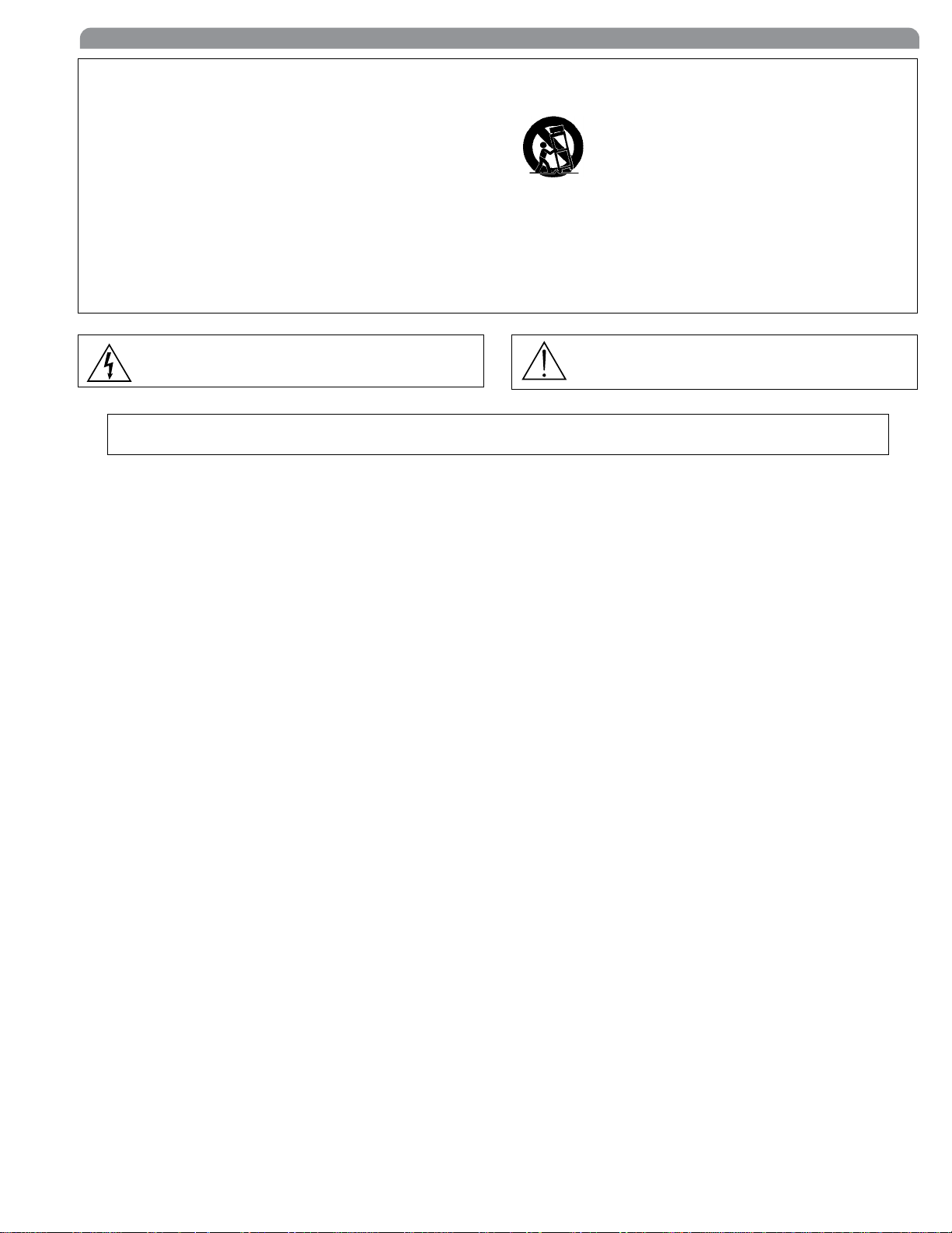
System Components
All systems include:
English
UR4S or UR4D Receiver
(UR4D pictured)
Two 1/2 Wave Antennas
2 Antenna hole plugs
4 Rack Mount Screws with Washers
AA Batteries
Two Antenna Cables
IEC Power Cable
IEC Power Extension Cable
Ethernet Network Cable with “Ruggedized” plug
Shure’s Wireless Workbench Software
Transmitter Carrying Cas
e
Handheld Systems Include:
쐃 Microphone Head (choice of SM58®, SM86, Beta 58A®, Beta
87A™, Beta 87C™ or KSM9/BK, KSM9/SL)
쐇 UR2 handheld transmitter
쐋 Microphone clip
쐃
쐇
쐋
Bodypack Systems Include:
Threaded TA4F Adapter
UR1 Bodypack Transmitter
7
Page 6
Shure UHF-R Wireless
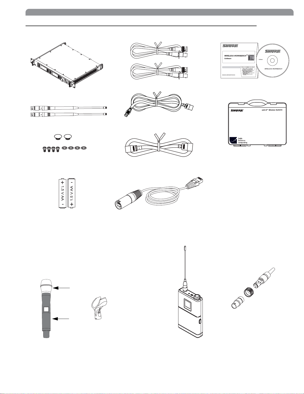
Receiver Controls and Connectors
18
17
UR4S
Wireless Receiver
with Audio Reference Conpanding
sync
234 5
RF Audio
OL
AB
XX YYY-ZZZ MHz Navigate
6 7 8
ENTER
EXIT
OFF
push
Monitor Clip
Monitor
Control
push
POWER
antenna B in
balanced low Z
line
12.7V out
mic
150mA
9
10 111112 13 14 15 16 17
receiver outputs
lift
GND
쐃 SYNC Infrared (IR) port. Transmits group, channel, and other
settings to a transmitter. See page 15.
쐇 Squelch LEDs.
• Blue (On) = Transmitter signal detected
• Off = no signal or signal squelched because of poor reception
or no tonekey
NOTE: The receiver will not output audio unless at least
one blue LED is illuminated.
쐋 RF LEDs. Indicate RF signal strength from the transmitter at
each antenna and diversity condition.
•Amber=normal
• Red = overload (greater than –25 dBm)
쐏 Audio LEDs. Indicate audio signal strength from transmitter.
• Green = signal present
• Yellow = normal peak
•Red=overload
To correct this level, adjust the transmitter gain.
쐄 Indicates the name and range of receiver frequency band.
쐂 LCD Interface. Provides a convenient way to program the
receiver from the front panel (see detail on next page).
쐆 Monitor. 1/4” output jack and volume knob for headphones.
•
Monitor Clip
•
Dual models
LED indicates headphone audio is clipping.
: Push the knob to switch from receiver one to r e-
ceiver two.
200ȍ
networking
network
activity
ethernet
RJ-45
antenna A in
12.7V out
150mA
쐊 Power switch. Powers the unit on and off.
쐎 AC mains power input, IEC connector. 100–240 Vac.
쐅 AC mains power passthrough (unswitched). Use with an IEC
extension cable to supply AC power to another device.
쐈 Diversity antenna inputs A and B.
Note: Antenna inputs are DC biased. Use only antenna
combiners and accessories listed in page 19. Some
types of antenna splitters or other products may short
the DC power and damage the receiver.
쐉 Mic/Line switch. Changes output level –30 dB (XLR output
only).
씈 Electrically balanced XLR output jack
씉 Lift/GND switch. Lifts ground from Pin 1 of the XLR connec-
tor (default = GND).
씊 Impedance balanced 1/4” output jack (200:)
씋 USB jack for computer interface.
씌 RJ-45 jack for Ethernet network interface. Accepts both regu-
lar and “ruggedized” RJ-45 plugs.
씍 Temperature-activated fan ensures top performance in high
temperature environments. Clean fan screen as needed to
remove dust.
8
Page 7
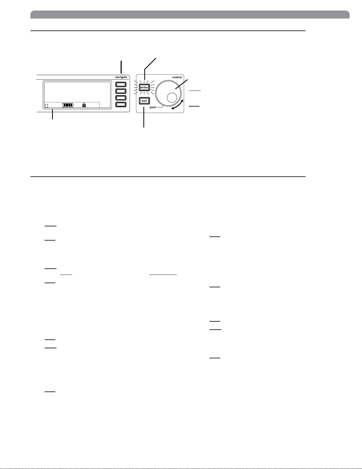
Receiver LCD Interface
Menu Access
Press the Navigate key next to the
menu item you want to select.
English
Accept Changes
After changing a parameter, the ENTER button flashes.
Press it to save the value.
SHURE
524-025 MHz TV: 32
G: 3 Ch: 1 Out: -0dB
+12 dB
+
Hi
F, P, FP
Radio
Audio
Util
Sync
Cursor Control
Push
the Control wheel to move the
cursor to the next item.
Turn
the Control wheel to change a
parameter value.
Transmitter Status Display
Everything under the dotted line reflects
the settings for the transmitter, if present.
(main title screen only).
Exit/Cancel
Press the Exit button to cancel changes and
return to the previous menu.
Receiver Parameters
Use the following instructions to set parameters through the LCD interface.
NOTE: After adjusting a parameter, you must press the flashing ENTER button to accept the change.
Group and Channel
Menu: Radio
•Push the
or Channel (
•Turn the
Control
Ch
) parameter.
Control
wheel to move the cursor to the Group (G)
wheel to change the parameter.
Frequency
Menu: Radio
•Push the
value (
•Turn
Control
741.000 MHz
the
Control
wheel to move the cursor to the integer
) or fractional value (
wheel to change the value.
741.025
Automatic Transmitter Sync
Menu: Sync
• See page 15.
Receiver Name
Menu: Util
•Turn the
•Push
the
Control
Control
wheel to change the letter.
wheel to move to the next letter.
Output Level
Menu: Audio
This setting adjusts the signal level at the XLR and 1/4” audio
output jacks.
•Turn the
(0 dB to –32 dB).
Control
wheel to change the relative level in dB.
).
• Turn the wheel all the way down to mute the outputs.
Squelch
Menu: Radio > Squelch
•Turn the
Control
wheel to change the parameter
Receiver Lock
When locked, the receiver settings cannot be changed from the
front panel. However, you can still navigate the LCD menu to
view the settings (and turn the lock off).
Menu: Util > Lock
•Turn the
OFF
).
Control
wheel to toggle the lock on or off (ON or
LCD View
Menu: Util > Title
•Turn the
•Push the
Control
Control
wheel to mark an item for display.
wheel to move to the next item.
LCD Contrast
Menu: Util > Contrast
•Turn the
Control
wheel to increase or decrease contrast.
Tonekey
Menu: Radio > Squelch > Tonekey
T onekey squelch mutes the outputs unless the receiver detects
a transmitter. Tonekey should be left on (On) except for certain
troubleshooting operations.
9
Page 8

Shure UHF-R Wireless
Network Parameters
NOTE:
• The receiver reboots after you press
work parameter changes
• In dual models (UR4D), these settings affect
(the dual receiver is treated as a single network device).
Set the Receiver Network Mode
Menu: Util > Network
1.
Push
the Control wheel to move the cursor to the Mode
parameter.
Turn
the Control wheel to set the receiver to one of the
2.
following values:
•
DHCP
: use this setting when connecting the receiver to a
DHCP server.
•
Manual
dress or subnet.
IP Address and Subnet
Menu: Util > Network
NOTE: To change these settings, the network mode must be
set to Manual.
Push
1.
following parameters:
•
IP
•
Sub
2.
Turn
: allows you to set the receiver to a specific IP ad-
the Control wheel to move the cursor to any of the
(IP address)
(Subnet mask)
the Control wheel to change the value.
ENTER
to accept net-
both
receivers
Device ID
Assists in identifying receivers through the Wireless Workbench Software (has no effect on network identification).
Menu: Util > Network
Push
1.
2.
the Control wheel to move the cursor to the
DevID parameter.
Turn
the Control wheel to set the receiver to change the
value.
Custom Groups
This feature allows you to create your own groups of
frequencies.
Creating new groups...
Menu: Radio > Custom
Turn
the Control wheel to select a custom group number
1.
(U1, U2, U3, etc.)
Push
2.
3.
4. Push the NEXT menu key to select a frequency for the
the Control wheel to move to the
Channel parameter and
channel (01, 02, 03, etc.)
Push
the Control wheel to move to the Freq parameter
and select a frequency for that channel.
next channel in that group.
turn
it to select a
10
Page 9

Automatic Frequency Selection
Follow these steps to use the channel scan and group scan features.
Before you begin...
• Install the receivers in the location where they will be used and power them on.
• Mute all inputs on mixing devices connected to receivers.
• Turn off all bodypack or handheld transmitters for the systems you are setting up.
• Turn on potential sources of interference such as other wireless systems or devices, computers, CD players, effects processors, and
digital rack equipment so they are operating as they would be during the presentation or performance.
Single Receiver
1. Select Radio > Scan > Chan Scan using the Navigate keys on the receiver LCD interface.
Turn
the Control wheel to select a group.
2.
3. Press Chan Scan. The display indicates that the receiver is searching. Once it has finished, it displays the selected channel.
4. Press the flashing ENTER button to accept the suggested channel.
5. Sync the transmitter (see page 15).
Networked or Dual Receivers
With networked or dual receivers, you can take advantage of the group scan feature to set group and channel settings for all the receivers at the same time. (See page 12 for instructions on networking.)
Perform a group scan from any receiver...
1. Select Radio > Scan > Group Scan using the Navigate keys on the receiver LCD interface. The display indicates that
the receiver is searching (Scan In Progress). Once it has finished, it displays the group with the most open channels.
2. If you wish, turn the Control wheel to change groups. The number of open channels for each group is displayed.
3. Press the flashing ENTER button to set all receivers to open channels in that group.
NOTE: The group scan feature only works for receivers in the same frequency band. For example, if you did a group scan on a
“H4” band receiver, all “H4” band receivers would be set up, but not “J5” band receivers.
English
Multiple Receivers—Not Networked
If your receivers are not networked (or in different bands), the group scan cannot automatically set their group and channel settings.
However, you can still take advantage of the group scan feature to find the group with the most open channels and the channel scan
feature to find open channels in that group.
Find the group with the most open channels...
Perform a group scan using the steps for a networked receiver (above). However, make a note of the selected group before pressing
the flashing ENTER button to accept it.
Set the receivers to open channels in that group...
Perform a channel scan on the remaining receivers using the steps for a single receiver (above). Make sure to select the same group
for each receiver before performing the channel scan.
IMPORTANT: After setting the channel for the first receiver,
that the next receiver detects that channel during its channel scan. Otherwise, all the receivers will be set to the same open
channel.
NOTE: Receivers in different bands (H4, J5, L3, etc.) do not need to be set to the same group.
immediately
sync the transmitter for that receiver and
leave it on
so
11
Page 10
Shure UHF-R Wireless
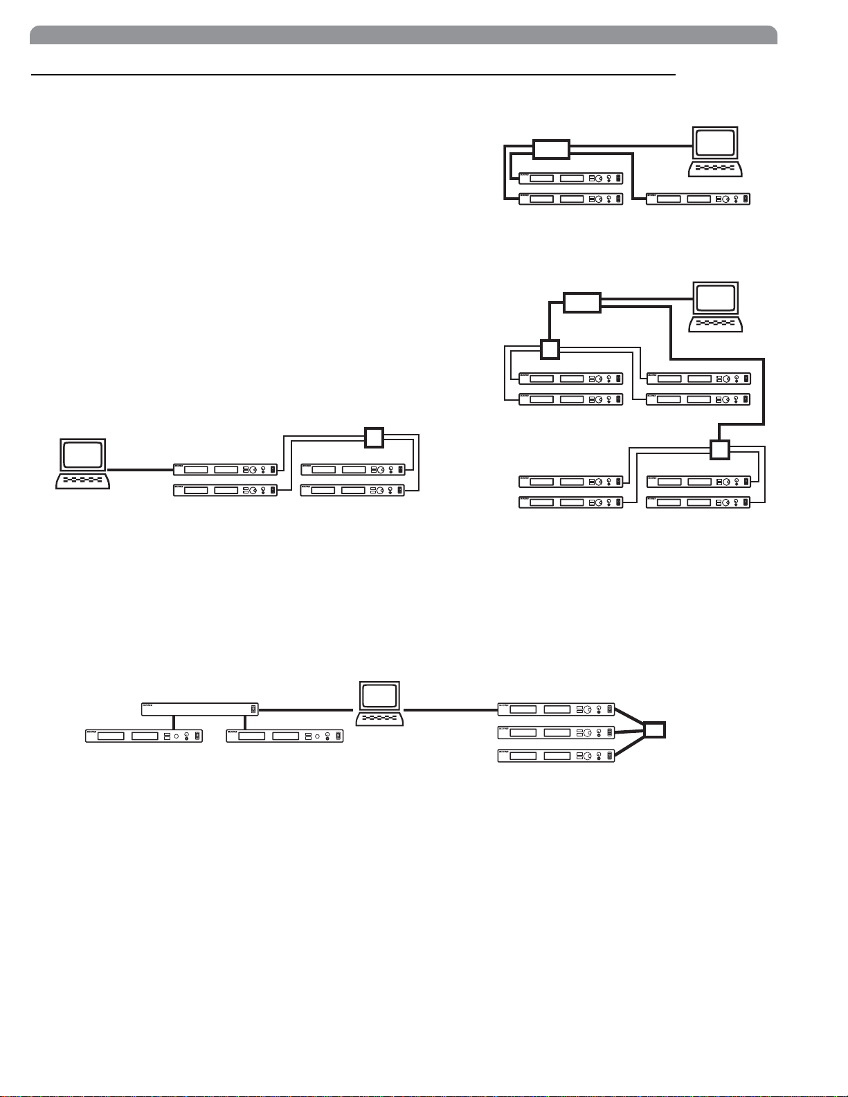
Networking Receivers
Basic Network
Connect receivers to an Ethernet router with DHCP service. Use Ethernet switches to extend the network for larger installations.
Use the receiver’s default network setting
(Util > Network > Mode = DHCP).
Accessing the Network with a Computer
If you want to use the Wireless Workbench software, connect your computer to
the network and install the software from the CD that came with the receiver.
Make sure your computer is configured for DHCP (from Control Panel, click Net-
work Connections. Double-click on Local Area Connection. Select Internet Protocol (TCP/IP) and click Properties. Select Obtain IP address automatically and
Obtain DNS server address automatically and click OK).
NOTE: Some security software or firewall settings on your computer can prevent
you from connecting to the receivers. If using firewall software, allow connections
on port 2201.
Using USB...
Connect the computer to the USB port on any of the receivers to access the
whole network.
Ethernet
USB
Computer
(optional)
Router with DHCP
Computer
(optional)
Router with DHCP
Switch
Switch
Static IP Addressing
The receiver also supports static IP addressing. Assign your own IP addresses ( Util > Network > Mode = Manual). See
“Network Parameters” on page 10.
NOTE: Dual receivers use a single IP address, which may be set through either LCD interface.
Existing UHF Network Installations
Both Shure’s UHF-R receivers and legacy UHF receivers can be networked to the same PC and accessed using the latest Wireless
Workbench software.
UHF
U888
USBRS-232
UHF-R
12
Page 11
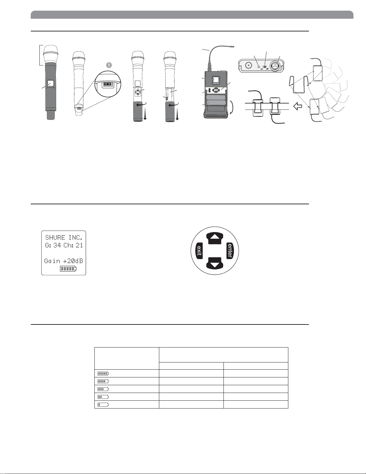
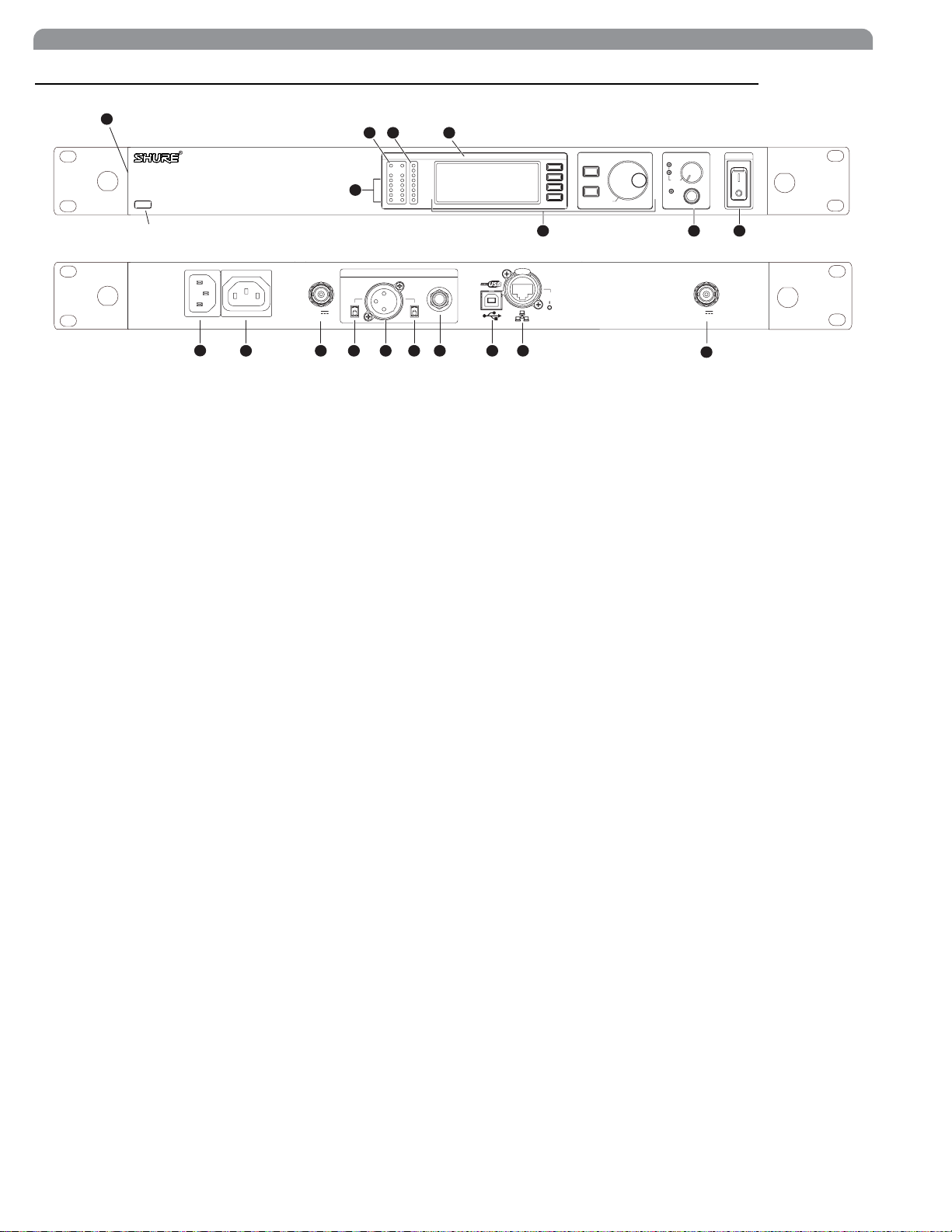
Handheld and Bodypack Transmitter Controls and Connectors
English
쐃 Interchangeable microphone head (BETA 87A pictured).
쐇 LCD Panel.
쐋 Power Switch.
쐏 Control buttons for LCD interface.
쐄 Infrared (IR) port. See page 15.
쐂 Battery compartment.
Transmitter LCD Interface
쐆
쐇
쐄
쐂
쐆 Flexible Antenna.
쐊 Power LED.
쐎 4-Pin Microphone Input Jack.
쐅 Reversible Belt Clip.
Up Arrow Key. Scroll up
or increase a value.
쐏
쐊
쐋
쐎
쐅
779.475MHz
Main Menu
exit Key. Move to the left, or exit
without saving changes.
Down Arrow Key. Scroll
down or decrease a value.
enter Key. Press to select parameters
and accept the selected value.
Transmitter Batteries
Transmitters operate on standard AA batteries. Turn off the transmitter before changing the batteries.
The battery fuel gauge displayed on the transmitter LCD gives an indication of remaining battery life, as shown below.
Approximate Hours Remaining
Transmitter Display
Normal Power High Power*
7.5 to 9.5 5 to 6
5.75 to 7.5 4 to 5
4 to 5.75 3 to 4
15 minutes to 2 hours 10 minutes to 1.5
* High power setting not available with models sold in countries that prohibit its use.
(alkaline batteries)
2 to 4 1.5 to 3
13
Page 12

Shure UHF-R Wireless
G
Ch
MHz
Gain
Sens
Transmitter Parameters
Press ENTER from the main menu to access the following parameters:
Group (
G:34 Ch:21
779.475MHZ
Gain +20dB
SHURE INC.
Use the following key combinations to access additional features and parameters:
taphold
LCD Panel
Changes LCD Panel
Frequency Lock
taphold
Toggles setting. When enabled, frequency cannot be changed, and a
transmitter sync will not overwrite the frequency setting.
Power Lock
taphold
Toggles power lock. When locked, power switch does not turn off
transmitter.
hold tap
RF power level setting*
Use the arrow keys to select normal (10 mW) or high power (50/100 mW**). Use the normal power setting
to conserve batteries or prevent RF overload at the receiver.
* High power setting not available with models sold in countries that prohibit its use.
** High power value varies with model.
Frequency (
Gain (
Sensitivity (
Sets audio input to +15 dB, 0 dB, or –10 dB.
Name Display. 12-digit ASCII.
) and Channel (
). Manual frequency selection in 0.025 MHz increments.
). Adjusts audio level from –10 dB to +20 dB.
) (bodypack only).
). Must match the receiver’s settings.
Lock Indicators
Power Lock
Frequency Lock
Setting Transmitter Gain
Adjust the transmitter gain and input sensitivity so that the Audio LEDs on the receiver peak within the yellow range during use. On
the bodypack transmitter, you can change the sensitivity setting to compensate for different audio levels when connecting different
intruments or microphones to the input.
To adjust gain, turn on the transmitter and press the enter button. Scroll down to the Gain parameter or the Sens parameter
(bodypack only) and press enter again. Use the arrow keys to adjust the setting and press enter to save it (Exit cancels without
saving).
RF Safety Mode
This special feature temporarily mutes RF broadcast. This allows you to change frequency settings on a transmitter without accidentally
“cutting in” on a channel being used by another transmitter.
1. Turn the transmitter off.
2. Hold down exit key while turning on the transmitter power (for handheld microphones, you need to pull the battery cover off the
handle). The LCD flashes while the unit is in RF safety mode.
3. Change group and channel settings as you normally would—the transmitter will not broadcast.
4. Power the transmitter off and on to exit RF safety mode.
14
Page 13

Automatic Transmitter Sync
Sync
sync
Sync
Setup
Sync
Setup
This feature automatically updates a bodypack or handheld transmitter’s group and channel settings to match those of a selected
receiver.
To perform a transmitter sync...
1. Open the transmitter battery cover to display the infrared (IR) port.
2. With the IR port exposed to the receiver, select
The display on the receiver indicates whether the sync was successful. If the sync fails, try again, making sure that the IR port on the
transmitter is exposed and directly faces the IR port on the receiver.
NOTE: Close the battery door before performing a sync on other transmitters.
®
Audio ABJ 779-810 MHz NavigateRF
OL OL
UR4D
Wireless Receiver
with Audio Reference
Companding
sync
>
from the receiver LCD interface.
Audio ABJ 779-810 MHz NavigateRF
Monitor
Control
ENTER
EXIT
sync
Power
1
2
push
Monitor Clip
English
To transfer other transmitter settings...
Optionally, you can transfer other transmitter settings from a receiver when you perform a sync. Use the following steps:
1. Select
>
2. Turn the Control wheel to change parameter settings.
3. Push the Control wheel to move to the next parameter.
4. Push the flashing ENTER button to save the settings.
The transmitter settings you set on the receiver remain for future syncs.
NOTE: If you don’t want the sync to send a setting, set the parameter to No Change
Available Settings...
The following settings are available from the
• Sensitivity (
• Gain (
•RF Power (
Gain
Sens
) bodypack only
)
Pwr
)
• Power and Frequency Lock (
Power lock only: (Pwr Only)
Frequency lock only: (Freq only)
Both: (Freq and Pwr)
Neither: (Unlocked)
• Custom Groups (
CG):
On (ON): Send custom groups to transmitters during sync
Off (OFF): Do not send custom groups (reduces sync time)
from the receiver LCD interface.
>
Lock
), which has the following values:
menu:
15
Page 14

Shure UHF-R Wireless
Troubleshooting
Faint Sound or Distortion Gain
Lack of range, unwanted noise bursts, or
Cannot turn transmitter off or change frequency
settings, or can’t program receiver
Excessive hum or buzzing Ground lift
Issue See Solution...
No sound Power, Cables, or RF
RF
drop outs
Interface Locks
Power
Make sure that the transmitter and receiver are receiving
sufficient voltage. The receiver requires at least 90 Vac. Check
the battery indicator on the transmitter and replace battery if
necessary.
Gain
Adjust the transmitter gain and sensitivity settings
(see page 14) or the receiver output level (page 9), or toggle
the mic/line switch on the back of the receiver.
Cables
Check that all cables and connectors are in working order.
Ground Lift
Lifting the ground on pin 1 of the XLR output on the receiver
can sometimes remove hum or buzz in the audio signal. Set the
GND/LIFT switch on the receiver to LIFT if you are using the
XLR connector.
Interface Locks
Both the transmitter and receiver can be locked to prevent accidental changes. On transmitters, look for a lock symbol on the
LCD and use the key combinations illustrated on page 14 to
turn it off.
To turn off the receiver interface lock, see page 9.
Radio Frequency (RF)
Using the RF LEDs
If neither blue RF LED is illuminated, then the receiver is not detecting the presence of a transmitter.
The amber RF LEDs indicate the amount of signal being received. This signal could be from the transmitter,
from an interfering source, such as a television broadcast.
the transmitter off. If more than one or two of the amber RF
LEDs are still illuminated, then that channel has too much interference, and you should try a different channel.
The red RF LED indicates RF overload. This will usually not
cause a problem unless you are using more than one system
at the same time, in which case, it can cause interference between systems.
or it could be
Turn
Compatibility
• Perform a transmitter sync, or make sure the transmitter and
receiver are set to the same group and channel.
• Look at the label on the transmitter and receiver to make sure
they are in the same band (H4, J5, L3, etc...).
Reducing Interference
• Use a different channel or perform an automatic group or
channel scan (see page 11).
• For multiple systems, check that all systems are set to channels in the same group (systems in different bands do not
need to be set to the same group).
• Maintain a line of sight between transmitter and receiver antennas
• Move receiver antennas away from metal objects or other
sources of RF interference (such as CD players, computers,
digital effects, network switches, network cables and Personal Stereo Monitor (PSM) wireless systems).
• Eliminate RF overload
Increasing Range
If the transmitter is more than 6 to 60 m (20 to 200 ft) from the
receiver antenna, you may be able to increase range by doing
one of the following:
• Reduce interference (see above)
• Increase transmitter RF power level
• Use an active directional antenna, antenna distribution system, or other antenna accessory to increase RF range (see
page 19).
Eliminating RF Overload
If you see the red RF LED on a receiver, reduce the transmitter
RF power level (see page 14) or move the transmitter further
away from the receiver
tive antennas, reduce antenna or amplifier gain.
(see below).
(see page 14).
—at least 6 m (20 ft)
. If you are using ac-
16
Page 15

Specifications
English
Frequency Range and Transmitter Output Power
Band Range Transmitter power (mW)
Handheld Bodypack
H4E,
518-578 MHz 10 / 50
H4
J5E,
578-638 MHz
(578-608, 614-638)
J5
L3E,
638-698 MHz 10 / 50
L3
10 / 50
10 / 50
10 / 50
10 / 50
10 / 50
10 / 100
10 / 50
10 / 100
10 / 50
10 / 100
Q5 740-814 MHz 10 / 50 10 / 50
R9 790-865 10 / 50 10 / 50
Q6 740-752 MHz 10 10
A24 779-788 / 797-806
10 10
MHz
JBX 806-810 MHz 10 10
Q10 740-798 MHz 10 / 50 10 / 50
This Radio equipment is intended for use in musical professional
entertainment and similar applications.
This Radio apparatus may be capable of operating on some frequencies not authorized in your region. Please contact your national
authority to obtain information on authorized frequencies and RF
power levels for wireless microphone products.
NOTE
RF Carrier Frequency Range
518-865 MHz, depending on region
Working Range
UR1, UR2: 150 m (500 ft.), under typical conditions
500 m (1600 ft) line-of-sight, outdoors
for a single system
NOTE: Actual working range depends on RF signal absorption, reflection and
interference
Audio Frequency Response
40 – 18,000 Hz, (+1 dB, –3 dB).
NOTE: Overall system frequency response depends on the microphone
element
Gain Adjustment Range
UR1: –20 to +35 dB
UR2:
–10 to +20 dB
Modulation
FM (45 kHz max. deviation), compander system with pre- and
de-emphasis
RF Power Output
See table above.
Dynamic Range
>105 dB, A-weighted
Image Rejection
>110 dB typical
RF Sensitivity
UR4S UR4D
–110 dBm Typical
12 dB SINAD
–105 dBm Typical
30 dB SINAD
–107 dBm Typical
12 dB SINAD
–102 dBm Typical
30 dB SINAD
Spurious Rejection
>90 dB typical
Ultimate Quieting (ref. 45 kHz deviation)
>100 dB, A-weighted
Signal Polarity
Positive pressure on microphone diaphragm (or positive voltage
applied to tip of WA302 phone plug) produces positive voltage
on XLR output pin 2 with respect to XLR pin 3 and on the tip of
the 1/4-inch output jack.
System Distortion (ref. ± 45 kHz deviation, 1 kHz modulation)
<0.3% Total Harmonic Distortion typical
Power Requirements
UR1, UR2: Two 1.5V AA batteries
UR4:100 to 240 Vac, 50/60 Hz
Current Drain
UR1, UR2: 180 mA max. (normal RF power setting)
240 mA max. (high RF power setting)
UR4D, UR4S: 0.8 Amps max.
Battery Life (Typical)
UR1, UR2: 9.5 hours (low power)
6 hours (high power)
Operating Temperature Range
–18° to +57° C (0° to +135qF)
NOTE: Battery characteristics may limit this range
NOTE: Electrical safety approval is based on a maximum
ambient temperature of 35°C (95°F).
Overall Dimensions
UR1: 98 mm L x 60 mm W x 17 mm D (3.84 x 2.38 x 0.66 in.)
UR2/SM58: 261 mm L x 51 mm Dia. (10.27 x 2 in.)
UR2/SM86: 261 mm L x 51 mm Dia. (10.27 x 2 in.)
UR2/SM87A: 254 mm x 51 mm Dia. (10 x 2 in.)
UR2/KSM9/BK, UR2/KSM9/SL: 250 mm x 49 mm Dia.
(9 7/8 x 1 15/16 in.)
UR2/BETA 58: 258 mm L x 51 mm Dia. (10.15 x 2 in.)
UR2/BETA 87A, UR2/BETA 87C: 254 mm x 51 mm
Dia. (10 x 2 in.)
UR4S/UR4D: 44 mm H x 483 mm W x 366 mm D
(1.72 x 19.00 x 14.39 in.)
Net Weight
UR1: 97 g (3.4 oz.) without battery
UR2/SM58: 356 g (12.6 oz.) without battery
UR2/BETA 58: 314 g (11.1oz.) without battery
UR2/SM86: 317 g (11.2 oz.) without battery
UR2/SM87A: 298 g (10.5 oz.) without battery
UR2/KSM9/BK, UR2/KSM9/SL: 410 g (14.5 oz.) without battery
UR2/BETA 87A, U2/BETA 87C: 325 g (11.5 oz) without battery
UR4S: 4.8 kg (10.6 lbs)
UR4D: 5.0 kg (11.0 lbs)
Housing:
UR1: Cast magnesium
UR2: Aluminum die-cast handle and aluminum machined
battery cup
UR4S, UR4D: Galvanized steel
Wiring
MICROPHONE
ELEMENT
NOTE: LAVALIER MIC TIES PINS 3 AND 4 TOGETHER—GUITAR CABLE DOES NOT.
Connector
TA4F
TA4M
Connector
UR1 MIC JACK BOARD
Active Load
Audio
Ground
17
Page 16

Shure UHF-R Wireless
Inputs and Outputs
UR1 Transmitter Audio Input
Connector: 4-Pin male mini connector (T A4M)
Input Configuration: Unbalanced, active
Actual Impedance: >1 M:
Maximum Input Level:
1 kHz, 1% THD
TA4M Connector
Pin Assignments:
UR1 Transmitter RF Output
Connector: SMA
Actual Impedance: 50 :
Pin Assignments: Shell = Ground
UR2 Transmitter Audio Input
Input Configuration: Unbalanced, active
Actual Impedance: >1 M:
Maximum Input Level:
1 kHz, 1% THD
UR2 Transmitter RF Output
Connector: SMA
Actual Impedance: 50 :
Pin Assignments: Shell = Ground
+10 dBu (sensitivity 0 dB)
+20 dBu (sensitivity –10 dB)
Pin 1: Ground
Pin 2: +5 Vdc bias
Pin 3: Audio
Pin 4: Tied through active load (on main
board) to Ground.
(On instrument adapter cable, Pin 4
floats)
Center = Signal
+4.8 dBu
Center = Signal
Receiver Input
Antenna Power
Connector Type: BNC IEC
Actual Impedance: 50: Nominal Input Level: –95 to –30 dBm 100-240 VAC,50/60 Hz
Maximum Input
Level:
Pin Assignments: Shell = Ground
Bias Voltage* 12.2 Vdc @ 150 mA
–20 dBm 240 VAC, + 10%, 50/60 Hz
Center = Signal
maximum
IEC Standard
N/A
* For remote antenna amplifiers
Receiver Audio Output
Monitor (1/4”
Headphone)
Output Configuration: Unbalanced
Actual Impedance: 50 : 200 : 200 :(active
Maximum Output Level 1 Watt @ 63 : +18 dBu +24 dBu
Pin Assignments: Tip = Hot
Phantom Power
Protection?
mono, 1/4 inch
Ring = Hot
Sleeve = Gnd
No Yes Yes
1/4” Phone XLR
Impedance
Balanced
Tip = Hot
Ring = no signal
Sleeve = Gnd
Electrically
Balanced
balanced)
(150 : mic)
(–6 dBu mic)
with 100 Hz
modulating tone
1 = Ground
2 = Audio +
3 = Audio –
Computer/Network Interface
Ethernet USB*
RJ45 USB Series B Receptacle
* USB-IF logo is a trademark of Universal Serial Bus Implementers Forum, Inc.
XLR
1/4” Monitor/headphone
1/4” Phone
18
Page 17

Replacement Parts and Accessories
English
Furnished Accessories
Microphone Stand Adapter (UR2) WA371
Zipper Bag (UR1) 26A13
Zipper Bag (UR2) 26A14
Antenna Extension Cables (2) 95A9023
Hardware Kit, Locking Connector WA340
Antenna (UR1), 518-578 MHz UA710
Antenna (UR1), 578-698 MHz UA720
Antenna (UR1), 740-865 MHz UA730
Two Antennas (UR4), Band
Dependent (see table)
Transmitter Carrying Case 95A9053
Optional Accessories
SM58 Head with Grille RPW112
SM86 Head with Grille RPW114
BETA 58 Head with Grille RPW118
BETA 87A Head with Grille RPW120
BETA 87C Head with Grille RPW122
SM87A Head with Grille RPW116
KSM9/SL Head with Grille RPW180
KSM9/BK Head with Grille RPW184
Matte Silver Grille (SM58) RK143G
Matte Silver Grille (SM86) RPM266
Matte Silver Grille (BETA 58) RK265G
Black Grille (SM87) RK214G
Matte Silver Grille (BETA 87A) RK312
Matte Silver Grille (BETA 87C) RK312
Black Grille (BETA 58) RK323G
Black Grille (BETA 87A/BETA 87C) RK324G
Popper Stopper Windscreen A85WS
Belt Clip 44A8031
Body-Pack Pouch (Black), UR1 WA580B
Body-Pack Pouch (White), UR1 WA580W
UA820
Antenna Combiners and Accessories
• Antennas and receivers must be from the same frequency
band.
• The supplied 1/2 wave antennas can be remotely mounted or
mounted directly to the UA845.
• Antennas and cables for use with the UA845 can also be
used with stand-alone UHF-R receivers.
Passive Antenna/Splitter Combiner Kit
(recommended for 2 receivers)
UHF Antenna Power Distribution Amplifier
(recommended for 3 or more receivers)
U.S.A.
Europe
1/2 Wave, Omnidirectional, Wideband
Antenna
Active Directional Wideband Antenna UA870WB
Wideband In-Line RF Amplifier UA830WB
Passive Unidirectional Wideband Antenna P A805WB
1/2 wave antennas (2)
H4E, H4 Bands
J5E, J5 Bands
L3E, L3 Bands
Q5, Q6, Q10 Bands
R9, ABJ Bands
25’ Antenna Cable (RG-8/X) UA825
50’ Antenna Cable (RG-8/X) UA850
100’ Antenna Cable UA8100
UK
UA221
UA845-
UA845US
UA845E
UA845UK
UA860WB
UA820H4
UA820J
UA820L3
UA820Q
UA820A
Architects' and Engineers' Specifications
The wireless system shall operate in the UHF band between 518 MHz and 865 MHz, with the specific range being dependent on the
user's locale. The system shall include the option of changing the operating frequency in order to avoid RF interference, enabling up
to 108 systems to operate simultaneously in the same location. Preconfigured group, channel and frequency setups shall be available
to ensure that multiple systems in use do not interfere with one another.
All transmitters shall be powered by 2 AA batteries and shall have a power on/off switch. The bodypack will have an LED indicating
that power is on. Available transmitters shall include: a body pack for use with electric guitars, basses, and other electric instruments,
and a handheld microphone for vocals. The transmitters shall have a DC/DC converter to ensure consistent performance, even if battery voltages change.
The receiver shall have a user-programmable, menu-driven LCD showing group, channel, frequency, name, squelch level, and
locked/unlocked status. The system shall use technology such as MARCAD
signal dropouts, and achieve the best possible signal-to-noise ratio. An equalizer, tone key squelch, and noise squelch circuitry shall
be built into the system to provide optimal sound quality and minimize unwanted noise. The receiver shall include dual RF meters (one
for each antenna), an audio level meter, and a Networking Interface connector for computer control and monitoring. The receiver shall
have a volume control and an adjustable noise squelch control.
The system shall be the Shure UHF-R Wireless.
£
signal combining circuitry to improve reception, minimize
19
Page 18

Shure UHF-R Wireless
Certification
UR1, UR2: Type Accepted under FCC Parts 74 (FCC ID: "DD4UR1" & "DD4UR2"). Certified by IC in Canad a un der RSS-123 a nd RSS102 ("IC: 616A-UR1" and "IC: 616A-UR2"). Meets the essential requirements of the European R&TTE Directive 99/5/EC (ETSI EN 300422 Parts 1 & 2, EN 301 489 Parts 1 & 9) and is eligible to carry the CE marking.
UR4S, UR4D: Authorized under the Declaration Of Conformity provision of FCC Part 15. Certified under Industry Canada to RSS-123
("IC: 616A-UR4"). Meets the essential requirements of the European R&TTE Directive 99/5/EC (EN 301 489 Parts 1 & 9, EN 300 422
Parts 1 and 2). Eligible to carry the CE marking.
Conforms to Australian EMC requirements and is eligible for C-Tick marking.
Have been granted the following Country Safety Approvals:
cULus Mark for US and Canada: Meets UL6500 and CSA/CAN E60065. UL GS-Certified to EN60065.
LICENSING INFORMATION:
Licensing: A ministerial license to operate this equipment may be required in certain areas. Consult your national authority for possible
requirements.
Changes or modifications not expressly approved by Shure Incorporated could void your authority to operate the equipment. Licensing of
Shure wireless microphone equipment is the user's re sponsibility, and licensability depends on the user's classification and ap plication,
and on the selected frequency. Shure strongly urges the user to contact the appropriate telecommunications authority concerning proper
licensing, and before choosing and ordering frequencies.
Information to User
This equipment has been tested and found to comply with the limits for a Class B digital device, pursuant to Part 15 of the FCC Rules.
These limits are designed to provide reasonable protection against harmful interference in a residential installation. This equipment generates, uses and can radiate radio frequency energy and, if not installed and used in accordance with the instructions, may cause harmful
interference to radio communications. However, there is no guarantee that interference will not occur in a particular installation. If this
equipment does cause harmful interference to radio or television reception, which can be determined by turning the equipment off and on,
the user is encouraged to try to correct the interference by one or more of the following measures:
• Reorient or relocate the receiving antenna.
• Increase the separation between the equipment and
• Connect the equipment into an outlet on a circuit different
• Consult the dealer or an experienced radio/TV technician
This Class B digital apparatus complies with Canadian ICES-003.
Cet appareil numérique de la classe B est conforme à la norme NMB-003 du Canada.
Operation of this device is subject to the following two conditions: (1) this device may not cause interference, and (2) this device must
accept any interference, including interference that may cause undesired operation of the device.
Note: EMC conformance testing is based on the use of supplied and recommended cable types. The use of other cable types may
degrade EMC performance
receiver.
from that to which the receiver is connected.
for help.
N108
20
Page 19

SYSTEM COMPATIBILITY GUIDE FOR FREQUENCY BANDS H4, H4E, J5, J5E, L3, L3E, Q5, Q9, R9, A24, JBX, Q6 AND Q10
SYSTÈMES COMPATIBLES EN FRéQUENCE DANS LA BANDES H4, H4E, J5, J5E, L3, L3E, Q5, Q9. R9, A24, JBX, Q6 ET Q10
FREQUENZKOMPATIBLE SYSTEME IM FREQUENZBEREICH H4, H4E, J5, J5E, L3, L3E, Q5, Q9. R9, A24, JBX, Q6 UND Q10
SISTEMAS CON FRECUENCIAS COMPATIBLES EN LAS BANDAS H4, H4E, J5, J5E, L3, L3E, Q5, Q9, R9, A24, JBX, Q6 Y Q10
SISTEMI COMPATIBILI IN FREQUENZA NELLA BANDAS H4, H4E, J5, J5E, L3, L3E, Q5, Q9, R9, A24, JBX, Q6 E Q10
SISTEMAS COM FREQÜÊNCIAS COMPATÍVEIS DA NA FAIXA H4, H4E, J5, J5E, L3, L3E, Q5, Q9, R9, A24, JBX, Q6 E Q10
H4 FREQUENCY BAND (518.000 - 578.000 MHz)
TV
22 & 27
Channel Group 1 Group 2 Group 3 Group 4 Group 5 Group 6 Group 7 Group 8 Group 9 Group 10
1 518.350 524.350 530.350 536.350 542.350 519.000
2 518.850 524.850 530.850 536.850 542.850 519.425
3 519.575 525.575 531.575 537.575 543.575 522.100
4 520.500 526.500 532.500 538.500 544.500 524.525
5 521.625 527.625 533.625 539.625 545.625 525.525
6 522.450 528.450 534.450 540.450 546.450 526.075
7 523.075 529.075 535.075 541.075 547.075 527.325
8 523.475 529.475 535.475 541.475 547.475 528.100
9 548.125 554.125 560.125 566.125 572.125 537.475
10 548.650 554.650 560.650 566.650 572.650 540.450
11 549.675 555.675 561.675 567.675 573.675 541.600
12 551.025 557.025 563.025 569.025 575.025 544.925
13 551.750 557.750 563.750 569.750 575.750 551.625
14 552.150 558.150 564.150 570.150 576.150 553.300
15 552.975 558.975 564.975 570.975 576.975 555.300
16 553.600 559.600 565.600 571.600 577.600 557.075
17 561.100
18 566.000
19 567.550
20 574.475
21 518.350
22 544.325
23 548.550
24 554.050
25 559.900
26 520.125
27 535.025
28 550.450
29 573.625
30 575.850
31 522.650
32 531.375
33 538.475
34 539.100
35 554.450
36 564.775
37 570.775 571.575 565.850
38 535.750 536.550 525.775
39 551.700 552.500 543.500
40 569.425 570.225 559.450
TV
23 & 28TV24 & 29TV25 & 30TV26 & 31
All Bands All Bands
519.250
521.625
525.800
526.375
528.075
533.950
535.500
538.350
542.400
543.475
547.350
553.625
561.075
565.700
569.050
570.775
571.550
572.800
573.425
573.825
519.875
520.275
522.425
546.925
555.750
521.050
536.475
537.250
539.250
544.000
548.950
552.050
561.975
566.200
567.125
575.050
Full
Spectrum
518.100 518.900 518.050
518.825 519.625 518.550
519.350 520.150 519.500
520.375 521.175 519.900
521.725 522.525 520.750
522.350 523.150 523.750
525.150 525.950 530.500
530.250 531.050 532.600
530.675 531.475 534.150
532.750 533.550 538.925
534.625 535.425 541.750
543.475 544.275 545.500
544.700 545.500 546.425
547.325 548.125 547.875
548.775 549.575 550.500
549.700 550.500 551.725
553.450 554.250 560.575
556.275 557.075 562.450
561.050 561.850 564.525
562.600 563.400 564.950
564.700 565.500 570.050
571.450 572.250 572.850
574.450 575.250 573.475
575.300 576.100 574.825
575.700 576.500 575.850
576.650 577.450 576.375
577.150 577.950 577.100
523.850 524.650 522.450
548.300 549.100 546.900
572.750 573.550 571.350
529.350 530.150 524.425
533.950 534.750 528.625
537.925 538.725 529.675
561.950 562.750 533.250
565.525 566.325 557.275
566.575 567.375 561.250
Full
Spectrum
Full
Spectrum
69
Page 20

J5 FREQUENCY BAND (578.000 - 607.975 - 614.025 - 638.000 MHz)
TV
32 & 37
Channel Group 1 Group 2 Group 3 Grou p 4 Group 5 Group 6 Group 7 Group 8 Group 9 Group 10
1 578.350 584.350 590.350 596.350 602.350 578.625
2 578.850 584.850 590.850 596.850 602.850 579.125
3 579.575 585.575 591.575 597.575 603.575 584.825
4 580.500 586.500 592.500 598.500 604.500 586.475
5 581.625 587.625 593.625 599.625 605.625 587.750
6 582.450 588.450 594.450 600.450 606.450 588.500
7 583.075 589.075 595.075 601.075 607.075 592.950
8 583.475 589.475 595.475 601.475 607.475 598.975
9 614.125 620.125 626.125 632.125 599.875
10 614.650 620.650 626.650 632.650 615.900
11 615.675 621.675 627.675 633.675 617.600
12 617.025 623.025 629.025 635.025 618.400
13 617.750 623.750 629.750 635.750 621.350
14 618.150 624.150 630.150 636.150 621.750
15 618.975 624.975 630.975 636.975 627.925
16 619.600 625.600 631.600 637.600 629.975
17 631.025
18 633.175
19 635.050
20 636.650
21 585.400
22 587.300
23 602.025
24 616.425
25 619.975
26 591.225
27 603.075
28 605.650
29 628.625
30 631.700
31 580.225
32 592.500
33 601.575
34 606.075
35 607.575
36 633.650
37 620.175
38 621.725
39 623.850
40 634.225
TV
33 & 38
TV
34 & 39
TV
35 & 40
TV
36 & 41
All Bands All Bands
581.650
586.625
588.025
592.275
595.225
597.675
601.750
602.175
604.300
607.675
614.425
620.650
622.025
623.800
625.000
630.175
632.250
633.750
636.275
637.075
587.450
598.975
627.775
632.825
637.575
583.175
588.950
590.825
596.900
599.425
600.700
614.975
616.700
619.525
623.050
635.775
Full
Spectrum
578.375 578.125 578.100
579.400 578.550 579.125
581.750
582.625
584.675
587.350
588.825
589.225
594.200
594.725
596.975
603.475
606.050
607.725
616.200
619.250
620.600
622.525
628.650
630.200
631.175
632.375
632.875
635.825
636.900
637.625
581.200
586.450
592.725
597.900
598.600
604.000
605.350
614.450
615.600
617.150
Full
Spectrum
579.200
580.600
581.150
584.500
585.375
588.950
591.175
593.925
595.225
604.150
604.875
606.275
618.025
620.825
621.975
625.325
627.250
630.500
632.325
633.100
635.275
636.175
636.700
637.700
582.425
587.650
588.050
598.350
599.575
600.600
603.700
607.075
614.925
615.600
617.025
619.900
622.500
631.150
Full
Spectrum
581.475
582.350
584.400
587.075
588.550
588.950
593.925
594.450
596.700
603.200
605.775
607.450
615.925
618.975
620.325
622.250
628.375
629.925
630.900
632.100
632.600
635.550
636.625
637.350
580.925
586.175
592.450
597.625
598.325
603.725
605.075
614.175
615.325
616.875
619.900
621.450
623.575
633.950
70
Page 21

L3 FREQUENCY BAND (638.000 - 698.000 MHz)
TV
42 & 47
Channel Group 1 Group 2 Group 3 Group 4 Group 5 Group 6 Group 7 Group 8 Group 9 Group 10
1 638.350 644.350 650.350 656.350 662.350 643.775
2 638.850 644.850 650.850 656.850 662.850 644.375
3 639.575 645.575 651.575 657.575 663.575 651.900
4 640.500 646.500 652.500 658.500 664.500 654.150
5 641.625 647.625 653.625 659.625 665.625 660.375
6 642.450 648.450 654.450 660.450 666.450 661.125
7 643.075 649.075 655.075 661.075 667.075 662.875
8 643.475 649.475 655.475 661.475 667.475 664.300
9 668.125 674.125 680.125 686.125 692.125 667.125
10 668.650 674.650 680.650 686.650 692.650 669.500
11 669.675 675.675 681.675 687.675 693.675 679.000
12 671.025 677.025 683.025 689.025 695.025 683.525
13 671.750 677.750 683.750 689.750 695.750 688.825
14 672.150 678.150 684.150 690.150 696.150 689.750
15 672.975 678.975 684.975 690.975 696.975 690.425
16 673.600 679.600 685.600 691.600 697.600 691.500
17 693.525
18 694.725
19 697.075
20 697.575
21 649.125
22 658.825
23 662.200
24 677.025
25 682.675
26 650.050
27 651.450
28 671.075
29 677.600
30 695.200
31 647.450
32 648.400
33 666.000
34 675.900
35 679.525
36 696.250
37 690.775 691.575 685.850
38 655.750 656.550 645.775
39 671.700 672.500 663.500
40 689.425 690.225 679.450
TV
43 & 48
TV
44 & 49
TV
45 & 50
TV
46 & 51
All Bands All Bands Full
Spectrum
649.800
650.800
653.000
659.550
660.775
661.350
665.425
668.050
675.575
679.750
683.450
684.875
686.800
691.750
692.300
693.050
693.500
695.550
696.200
697.100
645.875
658.800
663.675
664.800
678.400
646.825
648.050
651.275
657.075
662.350
674.950
679.350
680.750
682.500
685.450
689.700
638.100 638.900 638.050
638.825 639.625 638.550
639.350 640.150 639.500
640.375 641.175 639.900
641.725 642.525 640.750
642.350 643.150 643.750
645.150 645.950 650.500
650.250 651.050 652.600
650.675 651.475 654.150
652.750 653.550 658.925
654.625 655.425 661.750
663.475 664.275 665.500
664.700 665.500 666.425
667.325 668.125 667.875
668.775 669.575 670.500
669.700 670.500 671.725
673.450 674.250 680.575
676.275 677.075 682.450
681.050 681.850 684.525
682.600 683.400 684.950
684.700 685.500 690.050
691.450 692.250 692.850
694.450 695.250 693.475
695.300 696.100 694.825
695.700 696.500 695.850
696.650 697.450 696.375
697.150 697.950 697.100
643.850 644.650 642.450
668.300 669.100 666.900
692.750 693.550 691.350
649.350 650.150 644.425
653.950 654.750 648.625
657.925 658.725 649.675
681.950 682.750 653.250
685.525 686.325 677.275
686.575 687.375 681.250
Full
Spectrum
Full
Spectrum
71
Page 22

Q9 FREQUENCY BAND (740.000-805.975 MHz)
TV
59 & 64
Channel Group 1 Group 2 Group 3 Group 4 Group 5 Group 6 Group 7 Group 8 Group 9 Group 10
1 740.350
2 740.850
3 741.575
4 742.500
5 743.625
6 744.450
7 745.075
8 745.475
9 770.125
10 770.650
11 771.675
12 773.025
13 773.750
14 774.150
15 774.975
16 775.600
17
18 804.325 798.850 782.875 792.075
19 805.300 799.750 787.000 792.550
20 805.900 797.275 794.500
21 798.050 795.500
22 799.625 799.450
23 800.100 800.600
24 800.975 801.200
25 802.675 803.875
26 803.650 805.250
27 804.900 805.950
28 743.925 740.050
29 767.450 762.275
30 779.875 766.100
31 783.700 778.525
32 805.925 802.050
33 754.725 741.800
34 756.725 749.200
35 759.275 775.475
36 770.500 786.700
37 796.775 789.250
38 804.175 791.250
39 757.775 747.400
40 768.425 761.650
41 769.800 767.425
42 778.550 776.175
43 784.325 777.550
44 798.575 788.200
TV
60 & 65
746.350 752.350 758.350 764.350
746.850 752.850 758.850 764.850
747.575 753.575 759.575 765.575
748.500 754.500 760.500 766.500
749.625 755.625 761.625 767.625
750.450 756.450 762.450 768.450
751.075 757.075 763.075 769.075
751.475 757.475 763.475 769.475
776.125 782.125 788.125 794.125
776.650 782.650 788.650 794.650
777.675 783.675 789.675 795.675
779.025 785.025 791.025 797.025
779.750 785.750 791.750 797.750
780.150 786.150 792.150 798.150
780.975 786.975 792.975 798.975
781.600 787.600 793.600 799.600
TV
61 & 66
TV
62 & 67
TV
63 & 68TV 59 & 62 & 69TV 60 & 65 & 68
Full
Spectrum
740.050 746.075 740.025 741.075
740.575 746.925 740.725 742.325
742.000 747.325 742.100 743.300
743.725 748.075 744.775 745.000
744.625 749.775 745.375 745.875
745.250 750.275 746.525 746.350
758.300 751.250 750.475 747.925
758.700 751.875 751.475 748.700
759.425 776.125 753.425 758.975
760.750 776.550 753.900 763.100
761.750 779.100 766.125 765.025
763.600 780.100 770.925 766.500
800.175 780.775 771.625 772.200
800.875 781.875 773.200 772.775
801.275 795.200 773.775 774.350
802.125 796.550 779.475 775.050
803.825 797.325 780.950 779.850
Full
Spectrum
Full
Spectrum
740.225
740.925
742.300
744.975
745.575
746.725
750.675
751.675
753.625
754.100
766.325
771.125
771.825
773.400
773.975
779.675
781.150
783.075
787.200
797.475
798.250
799.825
800.300
801.175
802.875
803.850
805.100
741.375
744.175
754.975
755.375
756.075
759.675
768.475
769.400
769.975
778.750
782.000
784.750
786.775
787.825
791.875
798.750
804.300
72
Page 23

H4E FREQUENCY BAND (518.000 - 578.000 MHz)
Full Range
max. # of
comp. fre-
quencies
Channel Group 1 Group 2 Group 3 Group 4 Group 5 Group 6 Group 7 Group 8 Group 9 Group 10
1 518.100 518.900 518.750 518.750 518.100 518.500 520.225 518.300 518.500 518.575
2 518.825 519.625 519.500 519.500 521.500 520.025 522.025 519.000 522.250 520.300
3 519.350 520.150 521.250 520.500 522.975 522.225 522.775 522.025 523.675 521.750
4 520.375 521.175 523.250 521.750 525.700 522.975 525.900 524.000 524.500 522.300
5 521.725 522.525 524.250 523.250 532.500 524.900 526.300 530.025 526.350 526.350
6 522.350 523.150 527.500 526.750 532.900 530.225 533.500 532.700 528.000 527.525
7 525.150 525.950 535.250 527.250 534.500 536.775 535.000 533.500 528.500 527.975
8 530.250 531.050 536.500 531.500 538.975 540.900 536.225 533.900 531.900 531.800
9 530.675 531.475 543.750 537.250 544.775 545.500 541.500 542.300 535.075 535.400
10 532.750 533.550 547.750 547.500 546.975 549.300 550.300 546.775 542.700 536.275
11 534.625 535.425 548.250 550.750 550.100 550.500 557.100 549.900 543.425 540.975
12 543.475 544.275 550.750 554.500 561.500 556.500 560.975 560.225 552.550 547.975
13 544.700 545.500 552.500 562.500 565.300 556.900 562.775 560.975 553.725 551.225
14 547.325 548.125 561.750 563.500 565.700 568.025 568.225 568.225 565.425 551.950
15 548.775 549.575 567.500 569.250 568.025 570.975 570.775 570.775 566.025 552.950
16 549.700 550.500 571.250 571.750 572.500 572.900 572.000 572.700 568.125 557.250
17 553.450 554.250 574.750 572.250 574.100 573.700 572.700 573.100 571.675 558.400
18 556.275 557.075 575.750 575.750 576.025 576.025 574.300 574.300 572.150 558.800
19 561.050 561.850 577.250 576.500 577.500 577.500 576.975 576.975 573.675 561.800
20 562.600 563.400 577.750 577.750 520.775 518.100 520.975 520.975 576.650 568.375
21 564.700 565.500 520.500 528.500 534.100 525.300 525.100 528.225 536.075 525.650
22 571.450 572.250 521.750 529.250 538.225 528.775 536.975 540.700 556.975 553.600
23 574.450 575.250 530.500 530.500 540.900 533.300 540.000 544.225 560.575 567.575
24 575.300 576.100 531.250 538.500 541.700 533.700 542.300 550.300 519.125 523.575
25 575.700 576.500 534.750 540.250 546.225 546.225 556.000 556.000 521.700 533.050
26 576.650 577.450 537.250 543.750 549.700 549.700 556.700 556.700 539.550 556.700
27 577.150 577.950 540.250 544.500 552.025 552.025 557.900 557.100 554.600 566.125
28 523.850 524.650 546.500 545.750 560.775 554.975 566.300 557.900 558.050 572.000
29 548.300 549.100 551.500 551.500 564.500 565.700 575.000 562.775 539.025 518.050
30 572.750 573.550 554.500 552.500 566.500 568.775 576.225 566.300 540.725 536.675
31 529.350 530.150 555.500 556.250 573.700 572.500 545.100 538.375
32 533.950 534.750 560.500 558.750 556.125 571.175
33 537.925 538.725 563.500 559.750 557.400 573.100
34 561.950 562.750 564.250 567.500 570.000 575.250
35 565.525 566.325 569.250 568.500
36 566.575 567.375 570.500 569.750
37 570.775 571.575
38 535.750 536.550
39 551.700 552.500
40 569.425 570.225
(option 1)
Full Range
max. # of
comp. fre-
quencies
(option 2)
France
preferred:
User Group
A
(option 1
France
preferred:
User Group
A
(option 2)
France
preferred:
User Group
B
(option 1)
France
preferred:
User Group
B
(option 2)
France
preferred:
User Group
C
(option 1)
France
preferred:
User Group
C
(option 2)
All Bands All Bands
J5E FREQUENCY BAND (578.000 - 638.000 MHz)
Full Range
max. # of
comp. fre-
quencies
Channel Group 1 Group 2 Group 3 Group 4 Group 5 Group 6 Group 7 Group 8 Group 9 Group 10
1 578.375 578.375 578.500 578.500 578.225 578.225 578.775 580.000 589.375 581.050
2 579.400 579.100 579.250 579.250 578.975 578.975 580.000 580.700 590.525 582.400
3 581.750 580.175 579.750 582.750 580.900 580.900 582.300 581.100 591.175 583.950
4 582.625 583.125 583.250 583.250 582.500 581.300 583.000 581.900 595.300 584.950
5 584.675 583.625 585.750 585.750 585.500 582.500 584.975 584.975 596.350 585.700
6 587.350 584.825 587.500 591.750 593.500 586.975 589.100 591.000 600.375 589.250
7 588.825 585.800 593.250 593.250 594.975 592.025 592.225 594.775 601.875 589.900
8 589.225 587.350 595.500 595.500 597.300 598.500 597.100 597.500 602.825 591.125
9 594.200 593.475 598.750 604.250 604.900 606.100 597.900 605.900 604.925 593.350
10 594.725 595.400 610.500 607.500 605.700 608.775 605.500 606.300 605.700 599.100
11 596.975 596.750 611.250 608.500 606.100 609.500 608.975 608.225 616.900 610.300
12 603.475 599.800 615.500 609.250 610.975 610.975 610.775 610.775 622.650 611.075
13 606.050 608.275 623.250 617.750 624.775 620.900 621.500 621.100 624.875 613.175
14 607.725 609.950 623.750 623.250 626.975 624.775 623.000 624.975 626.100 614.125
15 616.200 612.525 625.750 623.750 628.900 628.900 628.000 626.775 626.750 615.625
16 619.250 619.025 631.750 625.750 630.500 630.500 628.700 631.000 630.300 619.650
17 620.600 621.275 633.250 633.250 636.500 634.225 634.775 634.025 631.050 620.700
18 622.525 621.800 634.500 634.500 636.900 634.975 636.700 634.775 632.050 624.825
19 628.650 626.775 635.500 635.500 637.700 637.300 637.100 636.000 633.600 625.475
(option 1)
Full Range
max. # of
comp. fre-
quencies
(option 2)
France
preferred:
User Group
A
(option 1)
France
preferred:
User Group
A
(option 2)
France
preferred:
User Group
B
(option 1)
France
preferred:
User Group
B
(option 2)
France
preferred:
User Group
C
(option 1)
France
preferred:
User Group
C
(option 2)
All Bands All Bands
73
Page 24

J5E FREQUENCY BAND (578.000 - 638.000 MHz) (Continued)
Channel Group 1 Group 2 Group 3 Group 4 Group 5 Group 6 Group 7 Group 8 Group 9 Group 10
20 630.200 627.175 636.250 636.250 580.500 637.700 637.900 637.500 634.950 626.625
21 631.175 628.650 583.750 580.250 584.775 586.225 578.025 584.225 594.000 586.250
22 632.375 631.325 585.250 587.750 596.900 588.500 594.025 596.000 620.625 595.375
23 632.875 633.375 599.500 590.750 598.100 589.300 594.775 598.300 629.750 622.000
24 635.825 634.250 600.500 594.500 598.500 600.025 596.700 605.100 579.850 593.850
25 636.900 636.600 601.750 599.750 600.775 604.500 606.300 608.975 580.950 607.800
26 637.625 637.625 602.500 601.750 610.225 605.700 610.025 620.700 586.800 629.200
27 581.200 581.775 603.750 602.500 616.775 614.100 621.900 621.900 608.200 635.050
28 586.450 592.150 606.750 603.500 621.700 621.700 626.775 622.300 622.150 636.150
29 592.725 594.275 608.500 611.250 626.225 626.225 630.300 624.225 598.250 581.900
30 597.900 595.825 609.250 615.500 630.100 626.975 631.000 630.300 606.250 598.100
31 598.600 598.850 612.250 619.250 634.225 630.100 611.900 603.050
32 604.000 600.400 619.500 620.250 634.975 636.500 612.950 604.100
33 605.350 601.550 620.250 625.250 617.900 609.750
34 614.450 610.650 625.250 626.500 634.100 617.750
35 615.600 612.000 626.500 631.500
36 617.150 617.400 633.750 632.500
37 620.175 618.100
38 621.725 623.275
39 623.850 629.550
40 634.225 634.800
L3E FREQUENCY BAND (638.00 - 698.000 MHz)
Full Range
max. # of
comp. fre-
quencies
Channel Group 1 Group 2 Group 3 Group 4 Group 5 Group 6 Group 7 Group 8 Group 9 Group 10
1 638.100 638.900 639.500 639.500 640.775 638.500 640.225 639.000 647.625 639.350
2 638.825 639.625 640.500 640.500 642.225 640.775 640.975 640.225 654.200 642.325
3 639.350 640.150 641.250 641.750 645.300 645.300 642.025 640.975 657.200 643.850
4 640.375 641.175 641.750 643.250 646.100 650.225 644.700 642.025 657.600 644.325
5 641.725 642.525 643.250 643.750 648.025 650.975 646.300 644.700 658.750 647.875
6 642.350 643.150 646.750 647.250 650.975 652.900 653.100 652.700 663.050 649.975
7 645.150 645.950 651.500 655.500 660.500 654.100 653.500 653.100 664.050 650.575
8 650.250 651.050 655.500 657.250 660.900 654.500 656.975 660.000 664.775 662.275
9 650.675 651.475 667.250 665.750 662.100 658.225 661.100 662.300 668.025 663.450
10 652.750 653.550 672.500 671.750 668.500 670.500 666.025 668.700 675.025 672.575
11 654.625 655.425 673.750 672.500 672.775 678.100 666.775 669.500 679.725 673.300
12 663.475 664.275 679.250 675.250 680.025 680.775 680.225 680.975 680.600 680.925
13 664.700 665.500 679.750 676.250 681.500 682.975 682.025 685.900 684.200 684.100
14 667.325 668.125 681.250 682.500 690.975 684.900 685.500 687.000 688.025 687.500
15 668.775 669.575 683.750 684.250 692.900 686.500 688.225 692.700 688.475 688.000
16 669.700 670.500 687.500 687.500 694.100 692.900 692.000 693.900 689.650 689.650
17 673.450 674.250 692.250 691.750 694.500 693.700 692.700 694.300 693.700 691.500
18 676.275 677.075 695.500 695.750 696.775 696.025 693.100 696.225 694.250 692.325
19 681.050 681.850 696.500 697.250 697.500 697.500 693.900 696.975 695.700 693.750
20 682.600 683.400 697.250 697.750 638.100 638.100 696.975 650.775 697.425 697.500
21 684.700 685.500 638.750 641.250 648.775 644.900 652.000 656.225 648.425 655.425
22 691.450 692.250 647.250 647.750 650.225 648.775 658.025 663.000 662.400 659.025
23 694.450 695.250 649.250 648.500 661.700 657.500 658.775 664.975 690.350 679.925
24 695.300 696.100 649.750 657.750 666.225 666.975 668.000 672.225 644.000 657.950
25 695.700 696.500 650.500 658.500 666.975 669.300 680.975 682.775 649.875 661.400
26 696.650 697.450 660.250 662.750 669.300 670.100 684.700 685.100 659.300 676.450
27 697.150 697.950 662.750 663.500 669.700 672.775 685.900 686.300 682.950 694.300
28 643.850 644.650 664.500 665.250 682.225 684.500 692.425 696.875
29 668.300 669.100 666.500 667.500 685.700 692.500 640.750 646.000
30 692.750 693.550 671.500 671.250 686.100 694.100 642.900 658.600
31 649.350 650.150 674.500 674.500 644.825 659.875
32 653.950 654.750 684.250 688.500 677.625 670.900
33 657.925 658.725 689.750 689.250 679.325 675.275
34 681.950 682.750 691.750 691.250 697.950 676.975
35 685.525 686.325 697.750 695.250
36 686.575 687.375
37 690.775 691.575
38 655.750 656.550
39 671.700 672.500
40 689.425 690.225
(option 1)
Full Range
max. # of
comp. fre-
quencies
(option 2)
France
preferred:
User Group
A
(option 1)
France
preferred:
User Group
A
(option 2)
France
preferred:
User Group
B
(option 1)
France
preferred:
User Group
B
(option 2)
France
preferred:
User Group
C
(option 1)
France
preferred:
User Group
C
(option 2)
All Bands All Bands
74
Page 25

Q5 FREQUENCY BAND (740.000 - 814.000 MHz)
Full Range
max. # of
comp. fre-
quencies
Channel Group 1 Group 2 Group 3 Group 4 Group 5 Group 6 Group 7 Group 8 Group 9 Group 10
1 740.300 740.425 740.100 740.625 740.250 740.250 742.750 740.900 740.500 740.900
2 740.825 740.850 740.625 741.050 742.750 743.250 743.500 741.300 740.900 741.300
3 742.400 742.100 742.200 742.300 743.250 743.750 745.250 742.100 742.100 746.975
4 742.800 742.650 742.600 742.850 744.500 745.250 746.500 744.025 744.025 748.900
5 745.000 744.025 744.800 744.225 746.500 746.500 747.500 745.500 744.775 749.700
6 745.975 744.675 745.775 744.875 747.250 753.750 751.750 749.300 746.225 752.025
7 748.850 745.600 748.650 745.800 752.500 755.500 753.250 754.225 756.900 753.500
8 749.950 750.050 749.750 750.250 759.750 763.500 753.750 760.025 761.500 764.500
9 753.350 752.625 753.150 752.825 767.500 769.250 758.750 770.975 764.500 768.775
10 756.100 753.525 755.900 753.725 768.500 771.250 771.750 774.100 770.975 774.100
11 764.875 758.825 764.675 759.025 769.750 772.250 775.500 774.500 772.900 776.025
12 770.150 766.275 769.950 766.475 771.750 774.750 776.500 781.300 773.300 778.975
13 771.800 769.350 771.600 769.550 772.250 775.500 777.750 782.500 776.775 781.700
14 772.575 770.025 772.375 770.225 786.500 785.750 787.500 784.025 778.225 782.500
15 774.325 771.300 774.125 771.500 794.500 791.750 791.500 786.225 778.975 784.775
16 776.625 777.375 776.425 777.575 796.250 795.500 799.750 786.975 796.500 796.500
17 782.700 779.675 782.500 779.875 799.750 800.500 801.750 802.975 797.700 800.775
18 783.975 781.425 783.775 781.625 803.500 801.250 803.250 806.100 806.500 804.500
19 784.650 782.200 784.450 782.400 806.750 803.250 804.250 808.025 808.025 805.700
20 787.725 783.850 787.525 784.050 807.500 807.500 807.500 809.500 810.225 810.225
21 795.175 789.125 794.975 789.325 809.750 808.500 809.250 812.500 810.975 810.975
22 800.475 797.900 800.275 798.100 811.750 809.750 809.750 813.300 813.700 812.900
23 801.325 800.650 801.125 800.850 812.250 811.500 810.500 813.700 753.500 813.300
24 803.950 804.050 803.750 804.250 748.250 745.750 744.500 746.225 754.975 744.775
25 808.400 805.150 808.200 805.350 750.750 750.750 745.750 753.500 757.700 746.225
26 809.325 808.025 809.125 808.225 755.750 752.500 751.250 758.100 766.500 750.100
27 809.975 809.000 809.775 809.200 759.250 753.250 754.500 758.500 781.700 765.300
28 811.350 811.200 811.150 811.400 762.500 754.500 755.500 765.300 788.500 768.025
29 811.900 811.600 811.700 811.800 763.500 758.750 759.500 768.775 789.300 772.500
30 813.150 813.175 812.950 813.375 766.750 760.500 760.500 769.500 792.025 773.700
31 813.575 813.700 813.375 813.900 770.500 767.500 766.750 772.900 792.775 781.300
32 754.400 751.050 754.200 751.250 775.500 770.500 770.500 788.900 797.300 792.025
33 768.000 772.025 767.800 772.225 779.500 776.500 771.250 797.300 798.500 794.975
34 778.000 776.000 777.800 776.200 782.750 777.750 779.500 801.500 800.775 797.300
35 781.975 786.000 781.775 786.200 783.250 779.250 782.750
36 802.950 799.600 802.750 799.800 784.500 782.750 784.500
37 743.550 746.200 743.350 746.400 785.250 784.500 785.250
38 750.400 755.625 750.200 755.825 788.250 785.250 785.750
39 751.425 768.400 751.225 768.600 791.750 786.500 786.500
40 785.600 802.575 785.400 802.775 795.500 788.250 790.750
41 798.375 803.600 798.175 803.800 798.750 796.250 793.250
42 807.800 810.450 807.600 810.650 800.500 801.750 800.500
43 767.400 754.825 767.200 755.025 808.500 810.500 808.500
44 768.950 758.375 768.750 758.575 810.500 812.250 812.250
45 769.700 763.725 769.500 763.925
46 790.275 784.300 790.075 784.500
47 795.625 785.050 795.425 785.250
48 799.175 786.600 798.975 786.800
(option 1)
Full Range
max. # of
comp. fre-
quencies
(option 2)
Full Range
max. # of
comp. fre-
quencies
(option 3)
Full Range
max. # of
comp. fre-
quencies
(option 4)
France
preferred:
User Group
A
(option 1)
France
preferred:
User Group
A
(option 2)
France
preferred:
User Group
A
(option 3)
France
preferred:
User Group
B
(option 1)
France
preferred:
User Group
B
(option 2)
France
preferred:
User Group
B
(option 3)
Q5 (Continued)
France
preferred:
User Group
C
Channel Group11 Group 12 Group 13 Group 14 Group 15 Group 16 Group 17 Group 18 Grou p 19 Group 20
1 741.100 740.700 741.100 790.100 790.100 790.250 790.300 790.350 790.400 791.475
2 741.900 741.100 741.500 791.050 791.575 792.325 791.250 791.300 790.800 792.525
3 742.300 742.300 742.300 793.575 792.050 792.900 792.950 794.925 798.800 793.200
4 743.000 743.000 744.975 794.675 794.425 793.725 794.875 795.450 803.500 795.625
5 748.700 750.300 746.025 803.200 796.250 795.350 795.400 801.000 804.725 797.125
6 751.000 752.975 748.000 804.425 797.500 799.900 796.150 803.450 805.700 802.525
7 754.025 757.900 752.225 806.100 799.575 800.900 798.700 806.350 806.400 804.850
8 765.500 759.000 757.500 806.500 806.600 807.200 801.775 806.750 808.475 805.250
9 768.225 770.775 759.000 811.200 809.325 810.825 807.950 808.425 809.050 808.550
10 768.975 772.700 773.100 811.950 810.425 812.100 808.375 809.825 809.875 809.950
11 770.025 774.300 773.500 813.400 812.950 812.575 809.775 813.650 810.975 811.550
12 775.000 778.025 776.225 813.900 813.900 794.825 812.625 793.825 792.475 812.850
13 778.775 781.100 776.975 796.425 790.600 808.325 806.700 796.675 793.875 813.775
14 780.700 782.300 780.000 797.400 805.500 811.350 810.875 797.650 794.975 799.400
(option 1)
France
preferred:
User Group
C
(option 2)
France
preferred:
User Group
C
(option 3)
Germany
preferred:
User Group
1 790-814
MHz
Germany
preferred:
User Group
2 790-814
MHz
Germany
preferred:
User Group
3A 790-814
MHz
Germany
preferred:
User Group
3B 790-814
MHz
Germany
preferred:
User Group
3C 790-814
MHz
Germany
preferred:
User Group
3D 790-814
MHz
Germany
preferred:
User Group
4 790-814
MHz
75
Page 26

Q5 (Continued)
15 783.000 784.975 781.900 797.900 805.900 811.400 809.000 795.500 810.525
16 797.500 786.775 784.225 800.750 808.800 813.600 810.925 796.725
17 797.900 797.900 788.700
18 799.000 800.225 802.025
19 805.100 804.000 804.700
20 806.300 805.100 805.100
21 808.225 807.000 805.900
22 808.975 808.225 810.025
23 810.775 812.700 812.000
24 813.100 813.500 813.500
25 746.775 744.225 752.975
26 749.100 748.700 754.025
27 752.225 749.100 756.700
28 754.775 752.225 774.300
29 756.700 754.775 782.300
30 764.000 764.000 788.000
31 782.300 768.225 789.100
32 784.225 772.000 789.900
33 784.975 780.700 792.975
34 788.000 791.000 802.775
35 792.225 794.025 806.300
36 813.900 794.775 810.775
Q5 (Continued)
MHz
Netherlands
pr e f e r r e d :
TV oh. 63
806-814
Germany
preferred:
User
Group 4
790-814
MHz
(option 2)
Germany
preferred:
Fixed In-
stallations
742-790
MHz
Optimized:
TV oh. 55
742-750
MHz
Optimized:
TV oh. 56
750-758
MHz
Optimized:
TV oh . 5 7
758-766
MHz
Optimized:
TV oh . 5 8
766-774
MHz
Optimized:
TV oh . 5 9
774-782
MHz
Broad-
casters
pre-
fe rred:
TV oh. 60
782-790
MHz
Optimized:
TV oh. 61
790-798
MHz
Optimized:
TV oh. 62
798-806
Channel Group 21 Group 22 Group 23 Group 24 Group 25 Group 26 Group 27 Group 28 Group 29 Group 30 Group 31 Group 32
1 790.925 742.750 742.100 750.100 758.100 766.100 774.100 782.225 790.100 798.100
2 791.400 744.625 742.925 750.925 758.925 766.925 774.925 782.650 790.925 798.925
3 792.625 745.100 743.525 751.525 759.525 767.525 775.525 783.900 791.525 799.525
4 795.025 745.975 744.575 752.575 760.575 768.575 776.575 784.625 792.575 800.575
5 795.650 747.650 745.900 753.900 761.900 769.900 777.900 785.775 793.900 801.900
6 797.050 748.225 747.650 755.650 763.650 771.650 779.650 786.400 795.650 803.650
7 802.000 753.225 748.050 756.050 764.050 772.050 780.050 787.325 796.050 804.050
8 803.575 754.750 749.200 757.200 765.200 773.200 781.200 787.850 797.200 805.200
9 805.750 755.950 749.900 757.900 765.900 773.900 781.900 788.675 797.900 805.900
10 810.300 759.350 746.600 754.600 762.600 770.600 778.600 794.600 802.600
806.100
806.925
807.525
808.575
809.900
811.650
812.050
813.200
813.900
810.600
11 811.050 762.275 760.925 766.550
12 812.850 770.100 770.900 767.425
13 813.775 774.375 774.450 773.025
14 799.400 775.775 776.400 773.525
15 808.550 777.500 777.475 776.625
16 779.750 778.875 777.950
17 782.550 783.075 781.950
18 784.475 796.800 783.775
19 785.975 797.975 798.600
20 787.050 804.325 804.250
21 788.350 806.225 808.800
22 788.875 741.200 748.175
23 743.500 773.450 752.600
24 772.075 775.700 770.875
25 755.450 810.100 778.900
26 756.750 745.475 783.375
27 770.825 754.900 766.125
28 772.725 762.625 771.775
29 776.450 768.825 786.450
30 789.875 783.575 802.075
31 760.000 797.575 812.900
32 783.925 755.525 745.950
33 756.650 749.375
34 758.975 763.475
35 781.700 788.125
36 807.675 800.900
MHz
Combined
UHF-R Q5
and R9:
max. # of
compatible
Combined
UHF-R Q5
compatible
Group 33
742.000 740.175
743.200 740.900
743.850 742.300
744.800 742.850
748.175 743.975
748.650 746.550
749.500 747.550
751.250 751.525
752.750 751.925
758.025 765.325
and R9:
max. # of
76
Page 27

R9 FREQUENCY BAND (790.000-865.000 MHz)
Full Range
max. # of
compatible
frequencies
(option 1)
Channel Group 1 Group 2 Group 3 Group 4 Group 5 Group 6 Group 7 Group 8 Group 9
1 790.650 791.300 790.725 790.525 790.175 790.525 792.550 792.625 790.250
2 791.900 792.050 791.825 791.125 793.025 791.775 794.000 793.175 792.325
3 794.200 793.225 792.500 791.925 793.425 792.400 794.525 794.025 792.900
4 795.275 793.875 794.950 794.025 798.225 793.550 797.200 795.625 793.725
5 795.975 795.375 795.375 795.850 799.100 796.150 799.400 797.750 794.825
6 797.425 798.050 796.900 798.125 799.600 797.100 801.200 801.225 799.200
7 797.975 798.475 801.725 801.725 800.675 803.025 802.175 805.100 799.900
8 802.175 800.925 802.675 802.750 801.325 804.500 805.750 807.425 804.100
9 803.725 805.425 803.975 803.225 805.975 805.000 809.125 810.100 810.825
10 804.650 806.700 804.750 809.975 809.900 807.225 811.575 810.525 812.100
11 808.600 809.050 809.275 816.025 810.875 810.525 812.825 811.600 812.575
12 814.550 812.050 817.225 818.000 813.450 812.100 813.250 813.300 839.200
13 817.550 823.825 820.550 818.575 838.175 813.450 840.625 854.950 839.900
14 823.625 825.000 823.175 819.375 838.975 854.325 841.425 856.625 840.325
15 828.275 826.550 827.825 821.500 840.125 854.975 843.725 857.475 842.825
16 829.100 829.700 829.375 822.400 841.875 855.900 845.100 857.950 844.100
17 830.625 831.500 829.875 828.575 843.225 857.700 845.800 859.050 846.250
18 831.625 832.550 830.625 829.250 847.975 858.850 848.525 859.725 847.200
19 833.275 842.775 834.825 830.275 850.975 860.750 849.125 861.175 856.900
20 833.875 844.100 842.650 835.075 851.475 863.175 853.800 861.750 857.725
21 841.575 846.575 844.050 843.050 853.125 864.000 855.400 791.450 860.100
22 846.050 851.125 845.900 851.975 855.625 864.475 857.950 801.950 795.350
23 851.950 853.475 853.025 852.800 857.475 792.825 859.650 805.775 807.200
24 855.900 857.750 855.000 855.125 861.475 795.750 861.150 863.525 807.900
25 856.825 858.525 855.600 856.475 863.775 805.750 795.700 864.200 811.350
26 858.425 858.950 856.725 856.975 864.175 806.300 800.625 856.325
27 859.050 860.725 859.050 858.025 864.825 807.875 810.100 859.350
28 860.550 863.350 859.450 861.575 790.800 810.975 810.550 860.575
29 863.400 863.900 863.625 863.625 794.350 811.700 839.475 863.100
30 863.825 864.875 864.350 864.325 794.775 857.225 849.925 863.675
31 864.625 794.775 801.000 792.450 804.225 861.300 854.950 864.475
32 799.275 799.800 822.000 827.450 805.400 857.200
33 822.150 825.575 827.200 845.000 806.800 863.200
34 830.225 827.075 860.975 845.600 808.600 863.675
35 847.400 845.700 864.875 794.775 811.475
36 807.375 855.450 791.425 795.175 840.800
37 810.825 811.600 803.425 806.125 843.850
38 815.825 813.825 808.825 809.225 844.275
39 816.300 819.850 834.400 811.875 849.325
40 820.250 841.075 840.050 813.275 860.725
41 821.050 845.100 851.950 830.700
42 839.850 847.800 861.800 831.725
43 842.400 813.400 807.475 834.425
44 843.925 816.725 822.425 843.750
45 845.150 818.975 835.800 847.250
46 846.625 840.675 840.500 848.375
47 853.775 856.100 843.525 849.900
Full Range
max. # of
compatible
frequencies
(option 2)
Full Range
max. # of
compatible
frequencies
(option 3)
Full Range
max. # of
compatible
frequencies
(option 4)
O p t i m i ze d :
TV oh. 61-63
& TV oh. 67-
69 & EU
harmonized:
790-814 &
838-862 MHz
& 863-865
MHz
O p t i m i ze d :
TV oh. 61-63
& TV oh. 69
& EU
harmonized:
790-814 &
854-862 MHz
& 863-865
MHz
Germany
preferred:
User Group
4 790-814
MHz &
838-865
MHz
(only
indoor)
Germany
preferred:
User Group
4 790-814
MHz &
854-865
MHz
(indoor and
outdoor)
Germany
preferred:
User Group
3A 790-814
MHz &
838-865
MHz
Germany
preferred:
User Group
3B 790-814
MHz &
838-865
MHz
Group 10
791.950
793.775
794.875
798.300
800.950
806.300
806.700
808.375
811.400
812.150
813.600
838.300
840.375
840.950
841.775
843.400
846.700
847.950
855.950
856.950
860.150
860.625
791.250
795.400
797.600
808.950
854.700
859.400
863.125
863.750
864.825
Germany
preferred:
User Group
3C 790-814
MHz &
838-865
MHz
Group 11
790.350
791.300
794.925
796.675
800.425
805.650
806.350
808.425
809.000
809.825
811.450
839.300
840.425
841.825
843.450
849.000
852.675
853.650
858.925
859.450
860.675
793.825
801.000
806.750
813.650
854.350
857.825
861.650
863.250
77
Page 28

R9 (Continued)
Germany
preferred:
User Group
3D 790-814
MHz &
838-865
MHz
Channel
Group 12 Group 13 Group 14 Group 15 Group 16 Group 17 Group 18 Group 19 Group 20
1 790.400 790.100 791.050 791.500 790.750 790.500 792.775 790.300 791.000 790.100 798.100
2 791.350 793.325 792.175 792.500 791.750 792.025 794.225 791.000 794.775 790.925 798.925
3 794.975 794.425 792.750 793.750 793.250 794.225 794.975 792.975 797.100 791.525 799.525
4 796.725 796.950 795.200 795.250 793.750 794.975 796.900 797.100 797.500 792.575 800.575
5 800.475 797.900 796.425 795.750 794.500 796.900 798.100 797.900 798.300 793.900 801.900
6 805.700 800.050 799.750 800.500 799.500 797.300 798.500 800.975 802.775 795.650 803.650
7 806.400 806.100 802.675 801.250 801.750 801.500 801.500 806.300 808.975 796.050 804.050
8 808.475 807.575 805.400 807.750 808.500 809.500 806.500 813.500 813.100 797.200 805.200
9 809.050 808.050 806.100 811.250 817.750 812.900 810.975 818.025 820.000 797.900 805.900
10 809.875 808.800 811.950 819.500 820.250 821.300 822.100 820.000 822.300 794.600 802.600
11 811.500 813.500 813.400 822.750 823.250 822.500 824.025 822.300 823.000
12 839.350 838.100 838.100 824.500 823.750 826.225 826.225 824.975 824.225
13 840.475 840.050 838.500 825.750 826.500 826.975 826.975 828.000 828.000
14 841.875 840.800 843.950 827.250 827.500 828.500 829.300 828.700 829.100
15 843.500 843.825 851.200 828.250 828.250 828.900 829.700 829.100 829.500
16 849.050 844.250 852.425 790.750 795.500 798.500 805.300 792.225 790.300
17 852.725 846.100 853.400 798.750 802.500 802.975 809.500 796.700 807.000
18 853.700 849.325 854.100 799.500 803.750 810.225 812.900 800.225 812.700
19 858.975 853.900 856.175 809.250 806.750 813.300 813.300 812.700 814.300
20 859.500 859.825 856.750 810.500 811.500 814.500 814.100 816.975 816.225
21 860.725 860.950 857.575 812.250 814.750 816.775 822.500 826.025 824.975
22 793.875 861.500 858.675 815.750 815.500 863.150 863.125 863.150 863.125
23 801.050 790.600 797.900 816.500 816.500 863.550 863.525 863.550 863.525
24 806.800 791.575 807.050 817.750 818.500 864.175 864.175 864.175 864.175
25 813.700 792.800 807.750 823.500 819.750 864.600 864.625 864.600 864.625
26 854.400 811.250 859.200 863.150 825.250
27 857.875 811.825 861.400 863.550 863.125
28 861.700 812.950 864.175 863.525
29 863.300 855.575 864.600 864.175
30 856.050 864.625
31 859.250
Germany
preferred:
User Group
2 790-814
MHz &
838-862
MHz
Germany
preferred:
User Group
1 790-814
MHz &
838-862
MHz
France
preferred:
User Group
A
(option 1)
France
preferred:
User Group
A
(option 2)
France
preferred:
User Group
B
(option 1)
France
preferred:
User Group
B
(option 2)
France
preferred:
User Group
C
(option 1)
France
preferred:
User Group
C
(option 2)
O p t i m i z e d :
TV oh. 61
790-798
MHz
Group 21 Group 22
O p t i m i z e d :
TV oh. 62
798-806
MHz
R9 (Continued)
Netherlands
pr e fer r e d:
TV Ch. 63
806-814 MHz
(option 1)
Channel
10 810.600 809.400 808.675 811.675 809.600 812.875 813.300 814.825 842.600 850.600
11 809.425 815.075 810.450 813.875 813.700 817.800
12 811.550 817.125 817.675 803.450 804.925 818.300
13 812.950 817.775 819.350 809.075 810.550 819.575
14 813.350 819.425 819.875 800.850
15 790.775 820.175 820.825 804.600
16 794.900 821.325 821.225 813.250
17 805.275 794.800 795.325 816.675
18 806.750 799.400 797.425
19 807.600 799.900 801.750
20 810.375 804.200 802.775
21 807.375 804.625
22 809.225 807.800
23 810.250 812.100
24 814.575 812.600
25 816.675 817.200
Group 23 Group 24 Group 25 Group 26 Group 27 Group 28 Group 29 Group 30 Group 31 Group 32
1 806.100 806.100 790.150 790.775 790.675 800.300 800.125 800.325 838.100 846.100
2 806.925 806.800 791.200 791.175 791.825 800.700 801.125 801.800 838.925 846.925
3 807.525 807.950 794.200 792.125 792.575 801.975 803.125 802.200 839.525 847.525
4 808.575 808.350 795.375 792.650 794.225 802.500 803.775 802.950 840.575 848.575
5 809.900 810.100 796.875 794.325 794.875 804.075 805.675 805.825 841.900 849.900
6 811.650 811.425 797.825 801.550 796.925 806.950 807.050 807.950 843.650 851.650
7 812.050 812.475 801.650 802.400 800.325 808.325 809.925 810.475 844.050 852.050
8 813.200 813.075 803.350 805.200 805.550 810.225 811.500 811.075 845.200 853.200
9 813.900 813.900 806.125 806.450 806.800 810.875 812.025 812.450 845.900 853.900
Netherlands
pr e f err e d:
TV Ch. 63
806-814 MHz
(option 2)
Opti m i z e d :
TV Ch. 61-63
790-814 MHz
FIN
pr e f er r e d:
7 9 0 - 8 2 2 M H z
(option 1)
FIN
pr e f err e d :
790-822 MHz
(option 2)
Sweden
pr e f er r e d:
800-814 MHz
(option 1)
Sweden
pr e f er r e d:
800-814 MHz
(option 2)
NOR / DEN
pr e f err e d :
800-820 MHz
Optimized
T V c h a n n e l s :
TV Ch. 67
838-846 MHz
Optimized
TV channels:
TV Ch. 68
846-854 MHz
78
Page 29

R9 (Continued)
BEL / TUR /
UK
p r e f e rr e d :
TV Ch. 69 &
EU
harmonized
854-862 &
863-865
MHz
Channel
Group 33 Group 34 Group 35 Group 36 Group 37 Group 38 Group 39 Group 40 Group 41 Group 42 Group 43
1 854.225 838.650 855.675 856.500 854.500 854.375 854.900 855.275 863.125 791.925 796.050
2 855.525 840.225 856.375 857.500 855.000 854.850 855.900 855.900 863.525 793.425 796.900
3 855.925 841.325 856.800 858.250 855.900 855.725 856.575 857.950 864.175 796.250 798.025
4 856.550 843.700 857.425 858.700 856.600 856.400 857.950 858.650 864.625 802.725 803.000
5 857.950 845.000 860.600 859.525 857.100 856.850 858.650 860.400 808.450 806.700
6 859.550 850.675 857.850 857.625 860.400 860.900 809.450 811.825
7 860.725 852.675 858.900 858.625 861.200 861.750 811.450 812.250
8 861.450 853.250 859.500 859.950 861.750 823.200 815.125
9 864.050 855.150 860.475 860.650 824.350 828.625
10 864.550 856.050 860.925 861.075 826.800 829.500
11 854.750 859.225 861.700 861.900 828.075 836.825
12 860.625 830.800 838.400
13 863.600 837.000 840.425
14 864.400 839.275 846.975
15 864.800 840.850 847.525
16 838.250 850.675 848.725
17 839.625 851.175 851.800
18 843.275 852.850 853.925
19 847.500 854.250 857.425
20 854.475 857.125 861.125
21 857.325 864.475 863.475
22
23
24
25
26
27
28
29
30
31
32
33
34
35
36
O p t i m i z e d :
TV Ch. 67-
69 & EU
harmonized
838-862 &
863-865
MHz
U.K.
preferred:
“Ch. 69 Co-
ordinate
frequencies
SET 1"
U.K.
preferred:
“Ch. 69 Co-
ordinate
frequencies
SET 2"
U.K.
preferred:
“Ch. 69 Co-
ordinated
frequencies
INDOORS"
U.K.
preferred:
"Ch. 69 Co-
ordinated
frequencies
OUTDOORS"
U.K.
preferred:
"Ch. 69
Shared
frequencies"
(option 1)
U.K.
preferred:
"Ch. 69
Shared
frequencies"
(option 2)
EU
harmonized
band:
optimized
for
863 - 865
MHz
Combined
UHF-R Q5
and R9:
max. # of
compatible
(option 1)
831.375 803.525
852.175 825.125
858.975 830.800
863.300 853.250
805.700 863.900
834.350 823.975
835.175 831.900
835.575 839.300
848.800 860.075
861.825 864.550
791.075 791.525
794.225 817.550
823.925 825.775
848.300 832.425
861.025 855.125
Combined
UHF-R Q5
max. # of
compatible
(option 2)
and R9:
79
Page 30

A24 FREQUENCY BAND (779-778 / 797-806)
Channel L1 L2 L3 L4 L5 L6 L7 L8
A1 779.125 779.250 779.625 779.750 780.625 780.250 779.125 782.875
A2 779.375 779.500 779.875 780.500 781.125 779.375 783.000
A3 780.125 780.000 780.375 781.000 781.375 779.875 783.125
A4 780.750 780.875 781.250 782.125 781.750 780.500 783.250
A5 782.000 781.500 781.625 782.375 782.625 781.500 783.375
A6 782.500 781.875 782.250 782.750 782.375 783.500
A7 782.750
1 797.125 797.250 797.625 797.750 798.625 798.250 797.125 800.875
2 797.375 797.500 797.875 798.500 799.125 797.375 801.000
3 798.125 798.000 798.375 799.000 799.375 797.875 801.125
4 798.750 798.875 799.250 800.125 799.750 798.500 801.250
5 800.000 799.500 799.625 800.375 800.625 799.500 801.375
6 800.500 799.875 800.250 800.750 800.375 801.500
7 800.750
Channel H1 H2 H3 H4 H5 H6 H7 H8
A1 783.625 783.750 784.125 784.250 785.125 784.750 783.625 787.375
A2 783.875 784.000 784.375 785.000 785.625 783.875 787.500
A3 784.625 784.500 784.875 785.500 785.875 784.375 787.625
A4 785.250 785.375 785.750 786.625 786.250 785.000 787.750
A5 786.500 786.000 786.125 786.875 787.125 786.000 787.875
A6 786.375 786.750 787.250 786.875
A7 787.250
1 801.625 801.750 802.125 802.250 803.125 802.750 801.625 805.375
2 801.875 802.000 802.375 803.000 803.625 801.8 75 805.500
3 802.625 802.500 802.875 803.500 803.875 802.375 805.625
4 803.250 803.375 803.750 804.625 804.250 803.000 805.750
5 804.500 804.000 804.125 804.875 805.125 804.000 805.875
6 805.000 804.375 804.750 805.250 804.875
7 805.250
Channel C1 C2 C3 C4 C5 C6 C7 C8 C9
10 787.500 787.125 787.625 787.500 787.875
Channel
779.125 779.500 779.250 779.500
1
779.375 779.875 779.750 780.000
2
780.875 782.375 780.500 780.750
3
781.875 784.125 782.000 782.250
4
783.750 786.500 782.625 784.000
5
786.125 787.500 783.750 785.375
6
787.250 787.750 785.750 786.000
7
8
9 787.000 786.500 787.375 787.250 787.625
E1 E2 E3 E4 E5 E6
1
797.125 797.500 797.250 797.500 797.125 797.250
2
797.375 797.875 797.750 798.000 797.375 797.500
3
798.875 800.375 798.500 798.750 798.125 798.000
4
799.875 802.125 800.000 800.250 799.625 799.375
5
801.750 804.500 800.625 802.000 801.625 800.500
6
804.125 805.500 801.750 803.375 802.250 801.375
7
805.250 805.750 803.750 804.000 803.375 802.875
8
9
10
ChannelF1F2F3F4F5F6F7F8F9
1 797.125 797.250 799.000 797.625 797.375 797.125 797.375 797.250 797.125
2 797.875 797.500 800.125 798.000 797.750 797.375 797.625 797.500 797.500
3 798.250 798.750 801.500 799.000 798.875 797.750 798.875 797.875 799.125
4 799.750 799.500 803.500 800.250 801.625 798.750 799.250 799.625 800.125
5 801.875 802.250 804.250 802.000 804.125 799.875 800.250 801.000 802.000
6 802.875 802.750 805.875 803.500 801.375 801.000 802.250 804.250
7 804.250 805.125 803.625 803.000 803.875 804.750
8 804.375 805.250 805.000 805.500
9 804.875 805.875
786.750 787.000
804.750 805.000 804.625 804.125
779.125 779.250 779.250 779.250 779.500
779.375 779.500 780.000 780.750 780.250
780.125 780.000 780.500 781.625 780.750
781.625 781.375 781.500 782.000 781.750
783.625 782.500 781.875 783.625 782.125
784.250 783.375 784.000 784.250 784.250
785.375 784.875 785.625 785.375 785.875
786.625 786.125 786.750 786.750 787.000
E7 E8 E9
797.250 797.250 797.500
798.000 798.750 798.250
798.500 799.625 798.750
799.500 800.000 799.750
799.875 801.625 800.125
802.000 802.250 802.250
803.625 803.375 803.875
804.750 804.750 805.000
805.000 804.500
805.500 805.125
805.375 805.250 805.625
805.625 805.500 805.875
80
Page 31

JBX FREQUENCY BAND (806-125, 809.750 MHz)
Channel Group 1 Group 2 Group 3 Group 4 Group 5 Group 6 Group 7
1 806.125 806.250 806.625 806.750 807.625 807.250 806.125
2 806.375 806.500 806.875 807.500 808.125 806.375
3 807.125 807.000 807.375 808.000 808.375 806.875
4 807.750 807.875 808.250 809.125 808.750 807.500
5 809.000 808.500 808.625 809.375 809.625 808.500
6 809.500 808.875 809.250 809.750 809.375
7 809.750
ChannelF1F2F3F4F5F6F7F8F9
1
2
3
4
5
6 806.125
7 806.375 807.000 806.375
8 806.250 807.625 808.125 807.250 807.125
9 806.750 808.750 809.000 807.750 807.750 806.125
10 809.500 809.375 809.375 808.875 809.000 806.750 808.500 806.875
11 809.750 809.750 809.625 809.750 809.500 808.750 809.125 808.375
12 809.625 809.625 809.125
808.000
808.625
809.500
809.750
Q6 FREQUENCY BAND (740.125 - 751.875 MHz)
Channel Group 1 Group 2 Group 3 Group 4 Group 5
1 740.275 740.275 740.250 740.275 740.375
2 741.000 740.825 740.900 740.800 741.275
3 741.450 741.725 741.325 742.550 741.700
4 742.425 742.250 742.075 743.350 743.450
5 742.850 742.975 743.025 743.775 743.925
6 743.600 743.450 743.475 745.525 744.775
7 744.050 744.425 744.525 748.125 746.975
8 745.050 746.825 745.375 748.925 748.700
9 747.450 747.825 747.925 749.350 749.600
10 748.425 748.275 748.375 751.250 750.925
11 748.900 749.025 749.200 751.775 751.650
12 749.625 749.450 749.625
13 750.150 750.425 750.250
14 751.050 750.875 751.100
15 751.600 751.600 751.600
81
Page 32

Q10 FREQUENCY BAND (740.000 - 797.900)
Works with
UA G1
Channel Group 1 Group 2 Group 3 Group 4 Group 5 Group 6 Group 7 Group 8 Group 9 Group 10
1 740.450 740.600 740.550 740.075 741.350 740.550 740.300 740.000 741.075 740.200
2 741.425 742.500 740.975 740.500 742.150 744.350 741.400 740.625 743.000 740.825
3 743.075 743.000 742.750 742.025 745.725 744.975 741.925 742.450 743.600 742.650
4 745.350 744.050 747.875 747.550 747.000 745.800 742.825 742.975 745.225 743.175
5 746.050 744.700 748.750 748.800 748.050 749.100 745.800 743.800 749.100 744.000
6 747.350 746.700 753.225 749.650 749.525 755.175 747.950 746.625 756.175 746.825
7 748.150 749.000 754.225 753.650 750.700 756.250 749.475 748.825 759.850 749.025
8 751.875 752.125 755.550 756.800 753.550 756.725 752.575 749.225 761.000 749.425
9 753.625 754.650 756.325 760.550 755.325 758.725 755.925 755.750 762.800 755.950
10 756.050 756.100 758.200 761.500 756.700 759.450 756.550 759.075 763.825 759.275
11 757.150 757.900 758.825 762.200 758.300 761.650 758.325 761.025 767.325 761.225
12 763.525 760.925 762.550 763.350 758.700 766.225 761.525 769.125 768.175 769.325
13 764.950 768.675 767.425 765.850 768.800 771.450 766.775 769.725 768.775 769.925
14 749.725 741.700 741.750 767.850 745.000 741.675 746.625 770.575 776.875 770.775
15 752.350 746.150 743.475 741.150 751.425 753.425 747.150 774.075 778.825 774.275
16 754.650 747.950 746.650 744.200 757.375 754.425 750.750 775.100 782.150 775.300
17 756.750 756.850 751.350 746.100 759.650 760.425 753.775 776.900 788.675 777.100
18 761.400 758.700 751.925 752.525 760.325 772.225 757.775 778.050 789.075 778.250
19 762.675 759.250 753.625 754.400 764.400 792.275 759.825 781.725 791.275 781.925
20 761.975 792.150 755.775 779.675 795.000 776.575 788.800 794.100 789.000
21 766.975 789.350 779.600 792.675 794.925 792.875
22 784.550 790.350 794.300 795.450 794.500
23 791.850 794.900 797.275 795.100
24 792.650 796.825 797.900 797.025
25 747.325 740.575 747.525
26 750.000 754.950 750.200
27 782.950 787.900 783.150
28 797.325 790.575 797.525
29 763.450 745.850 763.650
30 763.925 754.200 764.125
31 764.650 772.325 764.850
32 765.575 773.250 765.775
33 783.700 773.975 783.900
34 792.050 774.450 792.250
35 741.675 747.900 741.875
36 761.750 751.825 761.950
37 786.075 776.150 786.275
38 790.000 796.225 790.200
Works with
UA G2
Works with
UA G3
Works with
UA G4
Works with
UA G5
Works with
UA G6
Works with
UA G7
Full
Spectrum
Full
Spectrum
Full
Spectrum
82
Page 33

EU DECLARATION OF CONFORMITY
We, Shure Incorporated
of 5800 Touhy Avenue
Niles, Illinois, 60714-4608 U.S.A.
Phone: (847) 600-2000
Web: www.Shure.com
Declare under our sole responsibility that the following product
Model: UR1, UR2
Model: UR4S, UR4D Description: UHF Receivers
conforms to the essential requirements and other relevant previsions of the R&TTE Directive
(1999/5/EC).
The products comply with the following product family, harmonized or national standards:
EN 301 489-1 V1.4.1 (2002-08)
EN 301 489-9 V1.2.1 (2002-08)
EN 300 422-1 V1.2.2 (2000-08)
EN 300 422-2 V1.1.1 (2000-08)
In addition, the UR4S and UR4D products comply with the following product family,
harmonized or national standard;
EN60065
EN61000-3-2:2000 Amendment A1:1998; A2:1998; A14:2000
EN 61000-3-3 Amendment A1:2001
The technical documentation is kept at:
Shure Incorporated, Corporate Quality Engineering Division
SHURE Europe GmbH, EMEA Approval
Manufacturer: Shure Incorporated
Signed: __________________________________ Date: 6 January 2005
Name and Title: Craig Kozokar, EMC Project Engineer, Corporate Quality Engineering Division
Description: Body Pack and Handheld UHF Transmitters
European Representative: SHURE Europe GmbH
Signed: __________________________________ Date: 6 January 2005
Name and Title: Wolfgang Bilz, Dipl. Ing. (FH), EMEA Approval
SHURE Europe GmbH
Headquarters Europe, Middle East & Africa
Wannenäcker Str. 28
D-74078 Heilbronn, Germany
Phone: +49 - (0)7131 - 7214 - 0
Fax: +49 - (0)7131 - 7214 - 14
Page 34

)&&'(&/$5$7,212)&21)250,7<
:H 6KXUH,QFRUSRUDWHG
RI :7RXK\$YHQXH
1LOHV,/86$
000
'HFODUHXQGHURXUVROHUHVSRQVLELOLW\WKDWWKHIROORZLQJSURGXFW
0RGHO 856DQG85' 'HVFULSWLRQ 8+)5HFHLYHUV
+DVEHHQWHVWHGDQGIRXQGWRFRPSO\ZLWKWKHOLPLWVIRUDQXQLQWHQWLRQDOUDGLDWRUGHYLFHDQG
DSSURYHGXQGHUWKH'HFODUDWLRQRI&RQIRUPLW\SURYLVLRQRIWKH3DUWRIWKH)&&UXOHV
2SHUDWLRQLVVXEMHFWWRWKHIROORZLQJWZRFRQGLWLRQV
7KLVGHYLFHPD\QRWFDXVHKDUPIXOLQWHUIHUHQFH
7KLVGHYLFHPXVWDFFHSWDQ\LQWHUIHUHQFHUHFHLYHGLQFOXGLQJLQWHUIHUHQFHWKDWPD\
FDXVHXQGHVLUHGRSHUDWLRQ
6LJQHG 'DWH -DQXDU\
1DPH7LWOH &UDLJ.R]RNDU
(0&3URMHFW(QJLQHHU&RUSRUDWH4XDOLW\6KXUH,QFRUSRUDWHG
SHURE Incorporated http://www.shure.com
United States, Canada, Latin America, Caribbean:
Phone: 847-600-2000 U.S. Fax: 847-600-1212 Intl Fax: 847-600-6446
Shure Europe GmbH, Phone: 49-7131-72140 Fax: 49-7131-721414
Shure Asia Limited, Phone: 852-2893-4290 Fax: 852-2893-4055
5800 W. Touhy Avenue, Niles, IL 60714-4608, U.S.A.
Europe, Middle East, Africa:
Asia, Pacific:
 Loading...