

Shure UA UC, UC1, UC2/58, UC2/BETA 58, UC2/87 User Manual Supplement
...
CONTENTS
SPECIFICATIONS 2. . . . . . . . . . . . . . . . . . . . . . . . . . . . . . . . . . . . . . . . . . . . . . . .
Furnished Accessories 4. . . . . . . . . . . . . . . . . . . . . . . . . . . . . . . . . . . . . . . . .
Optional Accessories 5. . . . . . . . . . . . . . . . . . . . . . . . . . . . . . . . . . . . . . . . . . .
Replacement Parts 5. . . . . . . . . . . . . . . . . . . . . . . . . . . . . . . . . . . . . . . . . . . . .
FREQUENCY SELECTION GUIDE 6. . . . . . . . . . . . . . . . . . . . . . . . . . . . . . . . . .
Compatibility Groups 6. . . . . . . . . . . . . . . . . . . . . . . . . . . . . . . . . . . . . . . . . . .
Compatible Frequency List 7. . . . . . . . . . . . . . . . . . . . . . . . . . . . . . . . . . . . . .
UHF TV Channel Guide (for U.S. Channels 66–69) 8. . . . . . . . . . . . . . . . .
UC Wireless System
USER GUIDE SUPPLEMENT UA (782–806 MHz)
27C8636 (Rev. 3)
E2003, Shure Incorporated
Printed in U.S.A.

2
SPECIFICATIONS
RF Carrier Frequency Range
782–806 MHz
Working Range
152.4 m (500 ft), minimum, under typical conditions; 487.6 m (1600 ft ) line of sight
NOTE: Actual working range depends on RF signal absorption, reflection and inter-
ference.
Audio Frequency Response
45 to 15,000 Hz, ±2 dB.
NOTE: Overall system frequency response depends on the microphone element.
Gain Adjustment Range
UC1: –6 to 34 dB
UC2: –6 to 26 dB
Modulation
±45kHz deviation compressor-expander system with pre-and de-emphasis
RF Power Output
UC1, UC2: 50 mW, typical
Dynamic Range
>100 dB, A-weighted
Receiver Audio Output Level (Maximum)
+5 dBu typical, unbalanced output
+14 dBu typical, balanced output
RF Sensitivity
UC4: –108 dBm at 12 dB SINAD
Image Rejection
90 dB typical
Spurious Rejection
70 dB typical
Ultimate Quieting (ref. 45 kHz deviation)
>100 dB, A-weighted
Audio Polarity
Positive pressure on microphone diaphragm (or positive voltage applied to tip of
WA302 phone plug) produces positive voltage on pin 2 with respect to pin 3 of
low impedance output and the tip of the high impedance
1
/4-inch output.
System Distortion (ref. ±45 kHz deviation, 1 kHz modulation)
0.4% Total Harmonic Distortion typical
Power Requirements
UC1, UC2: 9V alkaline battery (Duracell MN1604 recommended); Nicad optional
UC4: 15 Vdc , 600 mA 50/60 Hz
Power Consumption: 600 mA x 15 V, maximum
Transmitter Battery Life (Typical)
8 hours (with Duracell MN1604 9V alkaline battery)
Operating Temperature Range
-7° to 49° C (20° to 120° F)
NOTE: Battery characteristics may limit this range.
Overall Dimensions
UC1: 99.06 mm L x 63.50 mm W x 22.86 mm D (3–29/32 L x 2–1/2 W x 29/32 in. D)
UC2/58:247.30 mm L x 50.8 mm Dia. (9–1/2 L x 2 in. Dia.)
UC2/BETA 58: 241.30 mm L x 50.80 mm Dia. (9–1/2 L x 2 in. Dia.)
UC2/87:215.90 mm x 50.80 mm Dia. (8–1/2 L x 2 in. Dia.)
UC2/BETA 87: 215.90 mm L x 50.8 mm Dia. (8–1/2 L x 2 in. Dia.)
UC4: 44.50 mm H x 197.40 mm W x 214.30 mm D (1–3/4 L x 7.77 W x 8.44 in. D)
3
Net Weight
UC1: 73.50 g (2.59 oz.) without battery
UC2/58, U2/BETA 58: 311.9 g (11 oz.) without battery
UC2/87, U2/BETA 87: 198.5 g (7 oz.) without battery
UC4: 1.22 kg (2 lbs, 11 oz.)
Certification
UC1, UC2: Type Accepted under FCC Parts 74. Certified by IC in Canada under RS 123.
UC4: UL and cUL Listed to UL 813 and CSA C22.2 No. 1. VDE Certified to EN 60 950.
Approved under the DoC provision of FCC Part 15; Certified by IC in Canada under
RS 123.
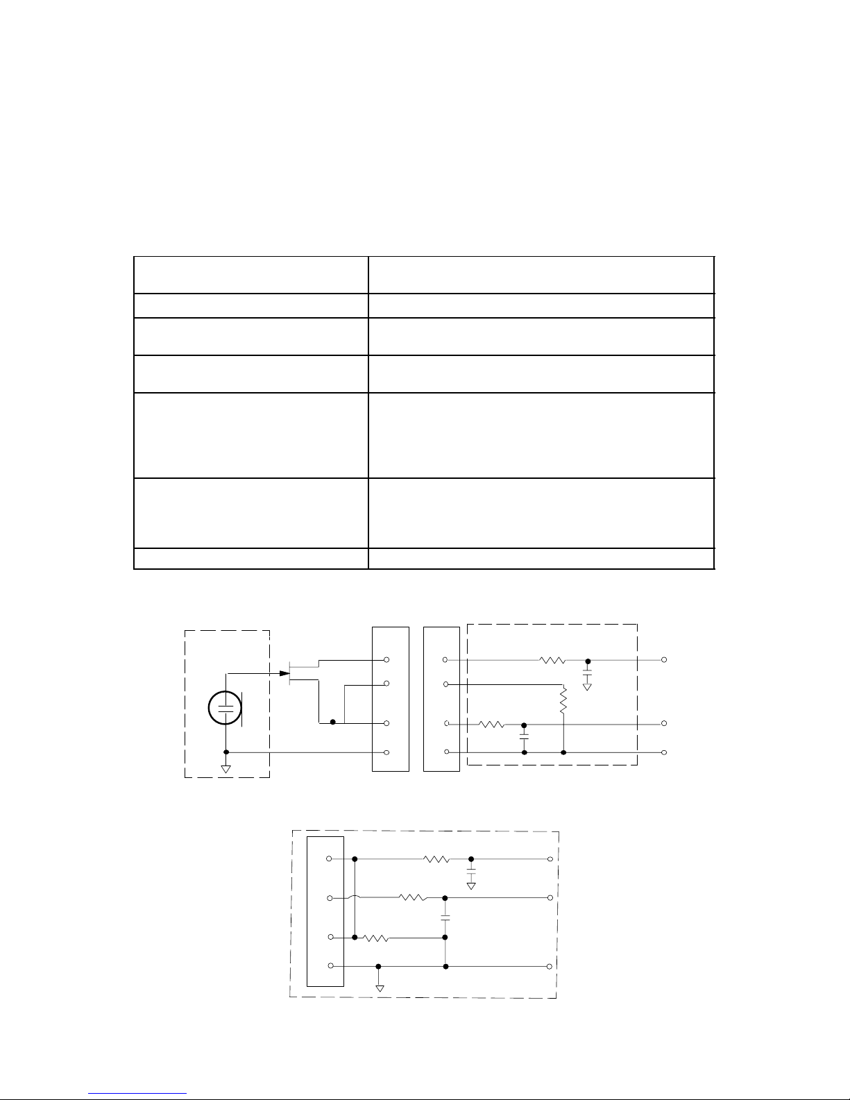
UC1 Transmitter Input (Figure 1)
Connector:
4-Pin female miniature connector (TA4F) or
LEMO connector (optional)
Input Configuration:
Unbalanced, active
Actual Impedance:
18 kΩ with lavalier microphone
1 MΩ with instrument cable
Maximum Input Level:
9 Vp–p (10 dBV) for 1% THD at minimum gain
setting using 1 kHz signal.
Miniature ConnectorTA4F Pin
Assignments:
Pin 1: Tied to Ground
Pin 2: Tied to +5 V
Pin 3: Tied to Audio
Pin 4: Tied thru 20 kΩ Resistor to Ground.
(On instrument adapter cable, Pin 4 floats)
LEMO Connector
Pin Assignments:
Pin 1: Tied to Pin 3 and 10 kΩ to Ground
Pin 2: +5V
Pin 3: Tied to Pin 1
Pin 4: Tied to Shield (Ground for Positive Bias)
Vol ta ge fo r Re mot e Po wer :
+5 V supplied to microphone cartridge
27 pF
20K Ω
27 pF
+5 V
AUDIO
GROUND
UC1 MIC JACK BOARD
2
1
4
500 Ω
500 Ω
MICRO-
PHONE ELE-
MENT
3
2
1
3
4
NOTE: LAVALIER MIC TIES PINS 3 AND 4 TOGETHER; GUITAR CABLE DOES NOT.
27 pF
499 Ω
499 Ω
3
27 pF
10K Ω
AUDIO
SHIELD
1
4
2
BIAS
UC1
UC1L (LEMO 4 PIN) MIC JACK BOARD
FIGURE 1
 Loading...