

Page 1
General Description
The Shure UA874 uses a log periodic dipole array to offer enhanced reception
when directed toward the desired coverage area. An integrated amplifier and
four gain settings compensate for varying degrees of coaxial cable signal
loss. The UA874 can be mounted on a microphone stand, suspended from
the ceiling, or mounted to a wall using the integrated swivel adapter.
Features
• Low-noise signal amplifier compensates for insertion loss in coaxial cable
Installation
• Connect the antenna to the receiver or distribution system using Shure
antenna cables (or any 50 ohm, low-loss coaxial cable, such as RG-8U).
• The antenna only operates with receivers or distribution systems that
provide 10–15 V DC bias.
• Lower the gain setting for short cable runs, or increase gain for longer
runs. Note that the quality of the cable, not just the length, contributes
to signal loss. A lighter-grade 50 foot cable may require more gain than
a 100 foot, low-loss cable. Contact the cable manufacturer for cable loss
specifications.
• Direct the antenna toward the intended coverage area.
• Do not use this antenna for transmitting (such as with PSM transmitters)
Cable Maintenance
To maintain top performance for antenna cables:
UA874Z
Active Directional Antenna
• Compatible with Shure wireless receivers and antenna distribution systems that provide 10–15 V DC bias
• Integrated threaded adapter mounts easily to microphone stands
• Four-position gain selector switch
• Shure quality, ruggedness, and reliability
Note:The antenna will not operatewithout 10-15 V DC bias. This is required
even at -6 dB and 0 dB ("passive") gain settings.
• Avoid sharp bends or kinks in the cables.
• Do not deform cables with makeshift clamps, such as bending a nail over
the cable.
• Do not use in permanent outdoor installations.
• Do not expose to extreme moisture.
Selecting Antenna Cables
Use 50 ohm low-loss coaxial cable, such as RG-8U. Shure offers pre-terminated antenna cables ranging from 6 to 100 feet.
NOTE:When ordering cables from Shure, select the low-loss "Z" models
(available for longer cables) when using frequency bands above 1000 MHz.
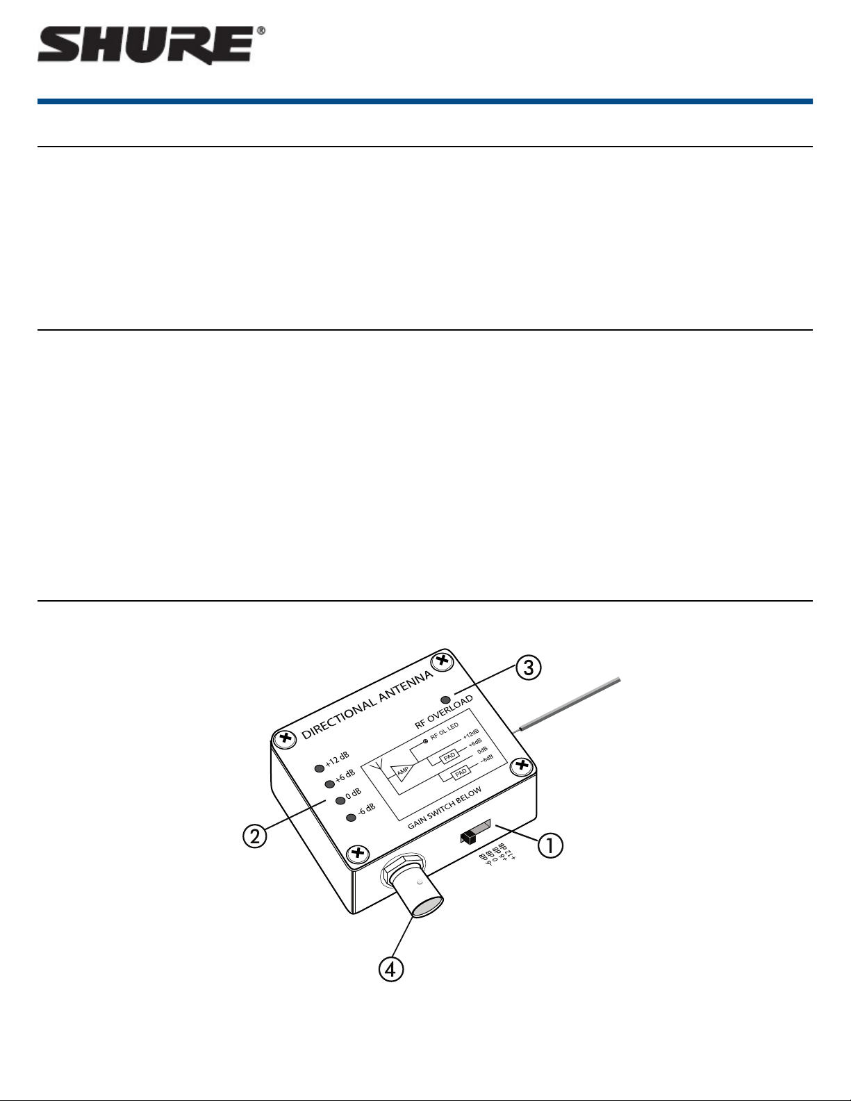
Interface
① Gain Switch
Adjust the four-position gain switch to compensate for the calculated cable loss, based on the length and type of cable.
Caution: There may be a small RF dropout when changing the gain setting.
1/4©2017 Shure Incorporated
Page 2
Shure IncorporatedUA874Z Active Directional Antenna
② Gain Mode LED
Indicates the current gain switch setting.
③ RF Overload LED
Indicates a strong RF signal that is overloading the antenna amplifier, which results in distortion or poor performance. Increase the distance between the antenna
and transmitter, or lower the antenna gain setting.
NOTE:RF Overload LED does not operate for passive gain settings (−6 dB or 0 dB).
④ BNC Connector
Connect to a receiver or antenna combiner with RF inputs that supply 10–15 V DC bias.
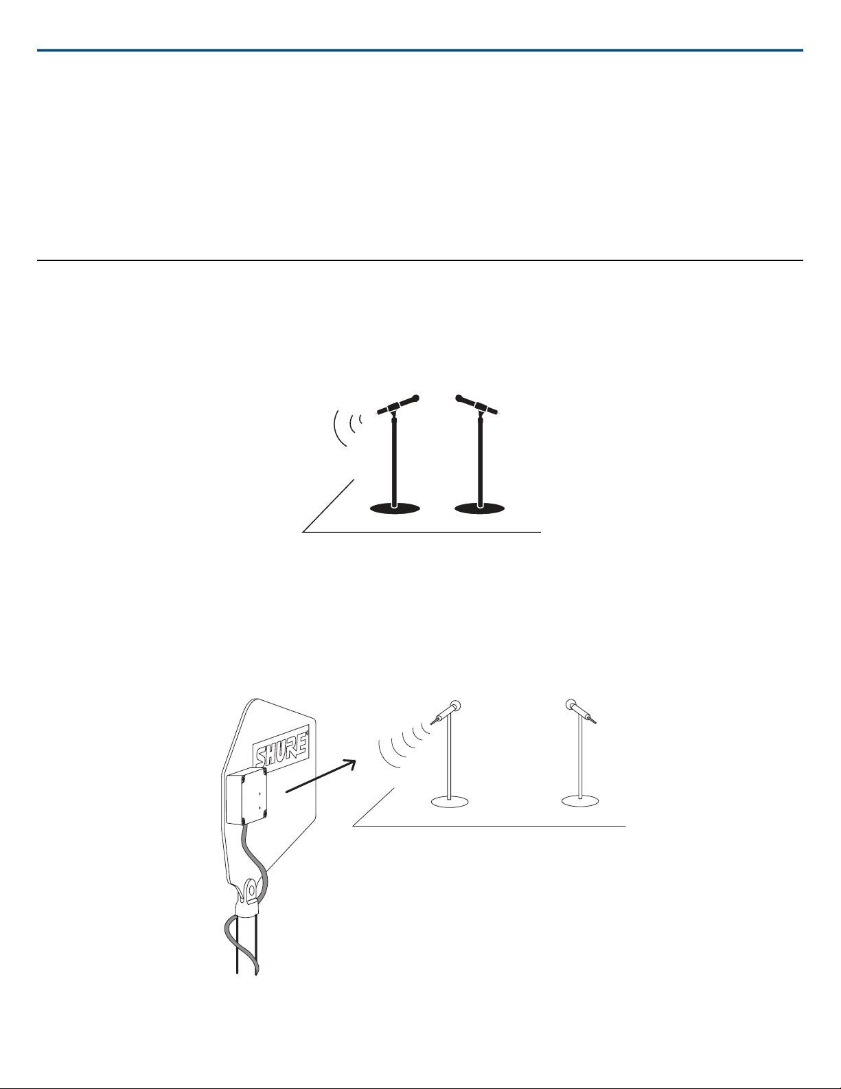
Antenna Placement
Use the following guidelines when mounting antennas:
• Antennas and receivers must be from the same band.
• Mount antennas at least one wavelength (two feet) apart.
• Position antennas so there is nothing obstructing a line of sight to the transmitter (including the audience).
• Keep antennas away from metal objects.
Important: Always perform a "walk around" test to verify coverage before using a wireless system during a speech or performance. Experiment with antenna
placement to find the optimum location. If necessary, mark "trouble spots" and ask presenters or performers to avoid those areas.
2017/11/022/4
Page 3

Setting Gain
The gain setting should only be used to compensate for the calculated cable
signal loss. Additional signal gain does not mean better RF performance.
Too much gain actually reduces reception range and the number of available
channels. This is because Shure receivers are optimized to deliver the best
performance when the sum of signal gain and cable loss equals 0 dB. Additional gain just amplifies everything in the RF range—including interference
and ambient RF noise. It cannot selectively increase the signal from the
transmitter.
• Use the lowest gain setting necessary to achieve good reception of the
transmitter RF signal, as indicated on the receiver’s RF LED or meter.
• Only increase the gain setting to compensate for the calculated cable
loss.
• The −6 dB gain setting can be useful for applications with short cable
runs (25 feet or less) and where the distance between the transmitter
and antenna is less than 100 feet.
Find More Information Online
For more information, visit http://www.shure.com
Shure IncorporatedUA874Z Active Directional Antenna
• Reduce gain if the antenna RF Overload LED illuminates—the signal is
strong enough, so gain is not needed.
Calculating Gain Settings
To calculate the required gain setting, obtain the cable manufacturer's
specification for signal loss. The rated loss usually varies with RF frequency
in addition to cable length.
Multiply the per 100 feet rating of the cable by cable length to determine
signal loss, and add gain as necessary to compensate. For example: a 50
ft. cable with rated loss of -12dB per 100 ft. would calculate as
(-12dB/100)*50 = -6dB and require +6dB of gain for a sum total of 0
dB loss.
Specifications
Connector Type
BNC, Female
Impedance
50 Ω
Power Requirements
10 to 15 V DC bias from coaxial connection, 75 mA
RF Frequency Range
470–698 MHzUA874US
470–790 MHzUA874E
470–900 MHzUA874WB
1240–1260 MHzUA874Z16
1492–1525 MHzUA874Z17
1785–1805 MHzUA874Z18
925–952 MHzUA874X
902–960 MHzUA874XA
Reception Pattern
3 dB Beam Width
70 degrees
Third-order Overload Intercept Point (OIP3)
>30 dBm
Antenna Gain
On Axis
7.5dBi
Signal Gain
±1 dB, Switchable
+12 dB, +6 dB, 0 dB, −6 dB
RF Overload LED Threshold
−5 dBm
0
Dimensions
316 x 359 x 36 mm (H x W x D)UA874
224 x 234 x 36 mm (H x W x D)UA874X
224 x 234 x 36 mm (H x W x D)UA874XA
224 x 234 x 36 mm (H x W x D)UA874Z
Weight
317 g (11.2 oz.)UA874
213 g (7.5 oz.)UA874X
213 g (7.5 oz.)UA874XA
213 g (7.5 oz.)UA874Z
Operating Temperature Range
−18°C (0°F) to 63°C (145°F)
Storage Temperature Range
−29°C (-20°F) to 74°C (165°F)
0
RF overload LED does not operate for passive gain settings
3/42017/11/02
Page 4

Certifications
This product meets the Essential Requirements of all relevant European directives and is eligible for CE marking.
The CE Declaration of Conformity can be obtained from:
www.shure.com/europe/compliance
Authorized European representative:
Shure Europe GmbH
Optional Accessories
Shure IncorporatedUA874Z Active Directional Antenna
Headquarters Europe, Middle East & Africa
Department: EMEA Approval
Jakob-Dieffenbacher-Str. 12
75031 Eppingen, Germany
Phone: +49-7262-92 49 0
Fax: +49-7262-92 49 11 4
Email: info@shure.de
WA874ZPProtective zipper pouch
Shure Incorporated 5800 West Touhy Avenue Niles, IL 60714-4608 USA Phone: +1-847-600-2000 Email: info@shure.com
4/4
 Loading...