

Page 1
Wireless Accessory
UA864
User Guide
Le Guide de l’Utilisateur
Bedienungsanleitung
Manuale d’uso
Guia del Usuario
Guida dell’Utente
Gebruikershandleiding
© 2013 Shure Incorporated
Printed in U.S.A
27A20829 (Rev. 3)
Руководство пользователя
Pengguna Panduan
取扱説明書
사용자 안내서
用户指南
*27A20829*
Page 2
General Description
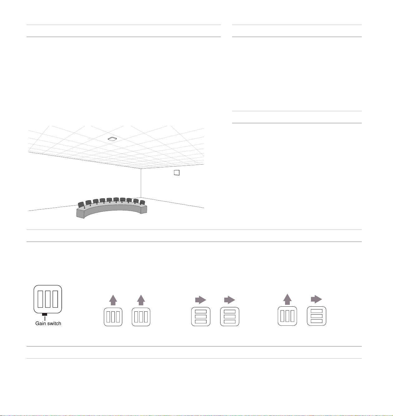
Gain switch
Features
The UA864 antenna provides wideband RF coverage in an easy to install, low-profile
enclosure that can be mounted on a wall, ceiling, and even on metal surfaces with improved reception. The paintable, neutral white housing allows the antenna to blend into
corporate or classroom settings. The 4-position selectable gain switch provides attenuation and boost settings to match the antenna to the environment.
Model Variations
UA864US: 470-698 MHz
UA864LO: 470-698 MHz
UA864HI: 530-790 MHz
UA864A: 650-952 MHz
• Wideband performance
• Low-profile design
• Wall or ceiling mounting options
• Four-position gain switch
• Metal surface mounting capability
• LED indicators for gain settings
• Neutral white, paintable housing
Antenna Placement
Use the following guidelines when mounting antennas:
• Antennas and receivers must cover the same
frequency range.
• Mount antennas at least four feet apart for optimal
diversity.
• Position antennas so there is nothing obstructing
a line of sight to the transmitter (including the
audience).
Positioning Antennas for Diversity Reception
The UA864 is a polarized antenna and must be oriented correctly to optimize reception for each transmitter type. Position the antennas using the following guidelines:
Note: Use the gain switch as an indicator of the antenna orientation.
Handheld and Bodypack Transmitters (vertical)
Boundary Microphones (horizontal) Mixed Transmitter Types (vertical and horizontal)
Find More Information Online
For setup tips and more information on wireless accessories, visit http://www.shure.com/WirelessAccessoryWizard
3
Page 3
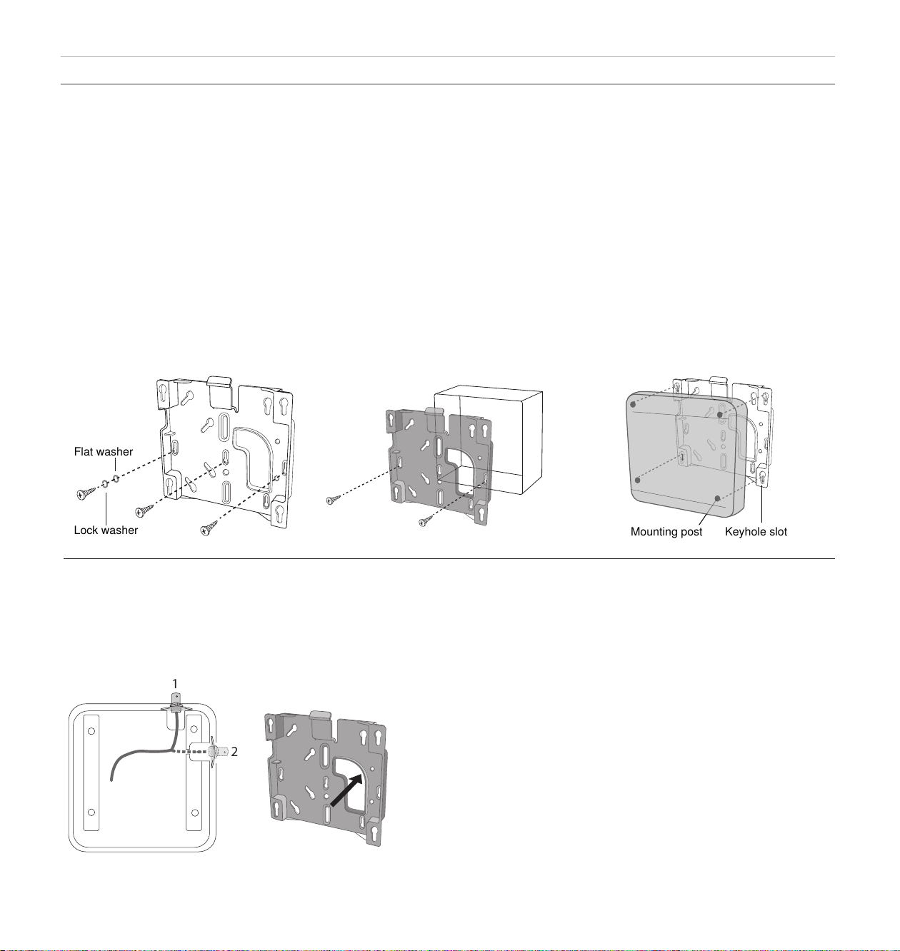
Installation
Flat washer
Lock washer
Mounting post
Keyhole slot
1
2
Mounting on a Wall or Ceiling
The mounting plate installs directly to a wall, ceiling, or a standard junction box.
Required Equipment
• #8 or #6 screws
• Flat washers
• Lock washers
• Drill
• Screwdriver
Mounting to a wall or ceiling
Installation Steps
1. Align the mounting plate:
Junction box mounting: Align the mounting plate with the junction box so that at least two screws can be used.
Wall mounting: Use the mounting plate as a template to mark the location for the holes on the mounting surface. Drill
the holes accordingly.
2. Secure the mounting plate to the surface with the washers as shown (CAUTION: Do not over-tighten screws).
3. If running RF cable from inside the wall, guide it through the opening in the mounting plate and connect the cable to
the antenna output.
4. Position the antenna mounting posts over the keyhole slots in the mounting plate and slide it into the locked position.
Mounting to an electrical junction box
Securing the antenna to the mounting plate
4
Routing the Cable
The output connector can be routed through ports 1 or 2 on the
antenna. When connecting to an RF cable in the wall, run the
cable through the opening in the mounting plate.
Rotating the Cover
The cover can be detached and rotated in any direction for a matched appearance when using multiple antennas.
1. Remove the screws holding the cover in place from the back of the antenna
2. Remove the cover and rotate to the desired position
3. Replace the screws to secure the cover
Painting the Antenna
The cover of the antenna can be painted to match the installation environment. Use the following guidelines when painting the antenna cover:
• Remove the antenna cover before painting
• Only use non-metallic paint, as any metallic content may interfere with
RF reception
• Allow the paint to dry completely before reinstalling the cover
• Avoid painting in the screw holes
Warning: Do not touch the internal components of the antenna when the cover is removed.
Page 4

Connecting to a Receiver
This antenna is compatible with any receivers, distribution systems, and splitters that operate within the antenna's frequency range. For receivers with
multiple antenna ports, connect each antenna being used to a separate port.
Note: The antenna requires bias voltage from the receiver or distribution system to operate on the +10 dB setting and for LED functionality. If these devices do not supply bias voltage, the Shure UABIAST
inline power supply can be used. The antenna still operates with all other gain settings if bias voltage is not supplied.
Setting the Gain Switch
Use the gain switch to optimize antenna performance for the RF characteristics of the room or location. Monitor the RF signal from the receiver to ensure
optimal signal strength.
RF Gain Setting (dB) Use Scenario
Pad: −10, −20 Provides increased isolation from other RF sources when the desired wireless microphone signal strength is strong. If
0 (Default) Suitable for typical room installations and provides enough RF gain in most cases when cable runs are between 10 and
Boost: +10 Provides an extra 10 dB of RF gain to compensate for signal loss if using long cable runs (50 feet or more).
Note: Bias power supplied by receiver antenna ports or an external power source is required for the +10 dB boost setting and for illuminating the LEDs. For un-powered applications, the -20, -10, and 0 dB
settings are still functional; however, the LEDs will not illuminate.
the RF OVERLOAD LED illuminates when using a higher gain setting, the pad should be used to attenuate the signal,
but only after verifying that the transmitter is an appropriate distance from the antenna.
50 feet.
Cable Maintenance
To maintain top performance for UA825, UA850 or UA8100 antenna cables:
• Avoid sharp bends or kinks in the cables.
• Do not deform cables with makeshift clamps, such as bending a nail over the cable.
• Do not use in permanent outdoor installations.
• Do not expose to extreme moisture.
5
Page 5

Specifications
Antenna Cables from Shure
Connector Type
BNC, Female
Impedance
50 Ω
Power Requirements
10 to 15 V DC bias from coaxial connection, 75 mA
RF Frequency Range
UA864US
UA864LO
UA864HI
UA864A
Reception Pattern
3 dB Beam Width at center frequency
UA864US
UA864LO
UA864HI
UA864A
Third-order Overload Intercept Point (OIP3)
>30 dBm
Antenna Gain
On Axis, 0 dB Gain Setting at center frequency
UA864US
UA864LO
UA864HI
UA864A
[1]
470–698 MHz
470–698 MHz
530–790 MHz
650–952 MHz
100 degrees
100 degrees
95 degrees
90 degrees
2.5 dBi
2.5 dBi
3.0 dBi
5.5 dBi
Shure offers the following pre-terminated antenna cables:
Length Type Model No.
6 foot RG58 UA806
10 foot RG58 PA725
25 foot RG8X UA825
50 foot RG8X UA850
100 foot RG213 UA8100
Certifications
This product meets the Essential Requirements of all relevant European
directives and is eligible for CE marking.
The CE Declaration of Conformity can be obtained from: www.shure.com/
europe/compliance
Authorized European representative:
Shure Europe GmbH
Headquarters Europe, Middle East & Africa
Department: EMEA Approval
Jakob-Dieffenbacher-Str. 12
75031 Eppingen, Germany
Phone: 49-7262-92 49 0
Fax: 49-7262-92 49 11 4
Email: EMEAsupport@shure.de
Signal Gain
±1 dB, Switchable
+10 dB
0 dB
−10 dB
−20 dB
RF Overload LED Threshold
−15 dBm
Dimensions
176 x 176 x 51 mm (H x W x D)
Weight
487 g (17.2 oz.)
Operating Temperature Range
−7°C (20°F) to 49°C (120°F)
Storage Temperature Range
−29°C (-20°F) to 74°C (165°F)
[1]
−20, −10, 0 dB settings do not require power
6
Page 6

Top ViewSide View
UA864US/
UA864LO
585 MHz
UA864HI
700 MHz
180˚
180˚
150˚
150˚
150˚
120˚
120˚
120˚
-15 dB
-15 dB
90˚
90˚
90˚
-10 dB
-10 dB
-5 dB
-5 dB
60˚
60˚
60˚
30˚
0 dB 5 dB
30˚
30˚
0 dB 5 dB
30˚
60˚
0˚
0˚
90˚
120˚
150˚
30˚
60˚
90˚
5 dB
0 dB
-5 dB
-10 dB
-15 dB
180˚
5 dB
0 dB
-5 dB
-10 dB
-15 dB
0˚
30˚
60˚
90˚
120˚
150˚
0˚
30˚
60˚
90˚
UA864A
790 MHz
180˚
150˚
150˚
150˚
120˚
120˚
120˚
-15 dB
30˚
-10 dB
-5 dB
60˚
60˚
60˚
30˚
0 dB 5 dB
30˚
0˚
90˚
90˚
90˚
120˚
150˚
30˚
60˚
90˚
120˚
150˚
180˚
0˚
5 dB
0 dB
-5 dB
-10 dB
-15 dB
180˚
120˚
150˚
30˚
60˚
90˚
120˚
150˚
Page 7

Europe, Middle East, Africa:
Shure Europe GmbH
Jakob-Dieffenbacher-Str. 12,
75031 Eppingen, Germany
Phone: 49-7262-92490
Fax: 49-7262-9249114
Email: info@shure.de
PT. GOSHEN SWARA INDONESIA
Kompleks Harco Mangga Dua Blok L No. 35 Jakarta Pusat
I.16.GSI31.00501.0211
 Loading...