

Page 1
MXW
®
Microflex Wireless
The Shure microflex wireless system, MXW, user guide.
Version: 4 (2019-G)
Page 2

Table of Contents
MXWMicroflex® Wireless 4
IMPORTANT SAFETY INSTRUCTIONS 4
Overview 4
General Description 5
Features 5
MXW Wireless System 7
Hardware Description 10
Audio Network Interface (ANI) 11
Access Point Transceiver (APT) 14
Networked Charger (NCS) 16
Microphone Transmitters 18
Rechargeable Batteries 24
Installation 29
Additional Equipment 29
Connecting MXW Components 30
Rack Installation 32
Securing the Charging Station 32
Two-Channel Charger Wall Mount 33
Mount the Access Point Transceiver 38
Power the Hardware 40
Open the MXW Control Software 41
System Set Up 42
Group Devices to Form Audio Channels 42
Channel Routing between Devices 46
Link Microphones to Group Channels 48
Preparing a Backup Microphone 50
Exchanging or Removing a Component 52
Link a Microphone Over the Network 52
Large Installations 53
Shure Incorporated
Shure SystemOn Software For Managing Large Systems 5
3
High Density Mode 53
Configurations: Managing Multiple Groups 53
Wireless Management 55
Overview of Channel Coordination 55
Scanning Available RF Spectrum 56
PHS Detection 57
Identifying PHS Detection Errors 58
Setting RF Power 59
Using Multiple 2- or 4-Channel Access Points 60
Networking 62
Networking Best Practices 62
Configuring IP Settings 63
Advanced Setup 65
Software 68
Shure Web Device Discovery Application 69
MXW System Control Software 70
Control Software for the MXW Audio Network Interface 82
Dante Software by Audinate 84
Firmware Updates 85
Troubleshooting 85
Additional Resources 87
Factory Reset 87
Accessories and Model Variations 88
Microflex Wireless Specifications 92
System 92
Transmitters 93
Access Point Transceiver (APT) 95
Networked Charging Station (NCS) 96
2/103
Page 3

Shure Incorporated
Audio Network Interface (ANI) 97
Transmitter Output Power 99
Wiring Diagram 100
Safety Information 100
SAFETY PRECAUTIONS 101
WARNING 101
WARNING 101
Important Product Information 101
Information to the user 102
Certifications 102
Trademarks 103
3/103
Page 4
MXW
Microflex Wireless
®
IMPORTANT SAFETY INSTRUCTIONS
1.
READ these instructions.
2.
KEEP these instructions.
3.
HEED all warnings.
4.
FOLLOW all instructions.
5.
DO NOT use this apparatus near water.
6.
CLEAN ONLY with dry cloth.
7.
DO NOT block any ventilation openings. Allow sufficient distances for adequate ventilation and install in accordance
with the manufacturer’s instructions.
8.
DO NOT install near any heat sources such as open flames, radiators, heat registers, stoves, or other apparatus (in
cluding amplifiers) that produce heat. Do not place any open flame sources on the product.
9.
DO NOT defeat the safety purpose of the polarized or grounding type plug. A polarized plug has two blades with one
wider than the other. A grounding type plug has two blades and a third grounding prong. The wider blade or the third
prong are provided for your safety. If the provided plug does not fit into your outlet, consult an electrician for replace
ment of the obsolete outlet.
10.
PROTECT the power cord from being walked on or pinched, particularly at plugs, convenience receptacles, and the
point where they exit from the apparatus.
11.
ONLY USE attachments/accessories specified by the manufacturer.
12.
USE only with a cart, stand, tripod, bracket, or table specified by the manufacturer, or sold with the apparatus. When a
cart is used, use caution when moving the cart/apparatus combination to avoid injury from tip-over.
Shure Incorporated
13.
UNPLUG this apparatus during lightning storms or when unused for long periods of time.
14.
REFER all servicing to qualified service personnel. Servicing is required when the apparatus has been damaged in any
way, such as power supply cord or plug is damaged, liquid has been spilled or objects have fallen into the apparatus,
the apparatus has been exposed to rain or moisture, does not operate normally, or has been dropped.
15.
DO NOT expose the apparatus to dripping and splashing. DO NOT put objects filled with liquids, such as vases, on the
apparatus.
16.
The MAINS plug or an appliance coupler shall remain readily operable.
17.
The airborne noise of the Apparatus does not exceed 70dB (A).
18.
Apparatus with CLASS I construction shall be connected to a MAINS socket outlet with a protective earthing connec
tion.
19.
To reduce the risk of fire or electric shock, do not expose this apparatus to rain or moisture.
20.
Do not attempt to modify this product. Doing so could result in personal injury and/or product failure.
21.
Operate this product within its specified operating temperature range.
4/103
Page 5
Shure Incorporated
Overview
General Description
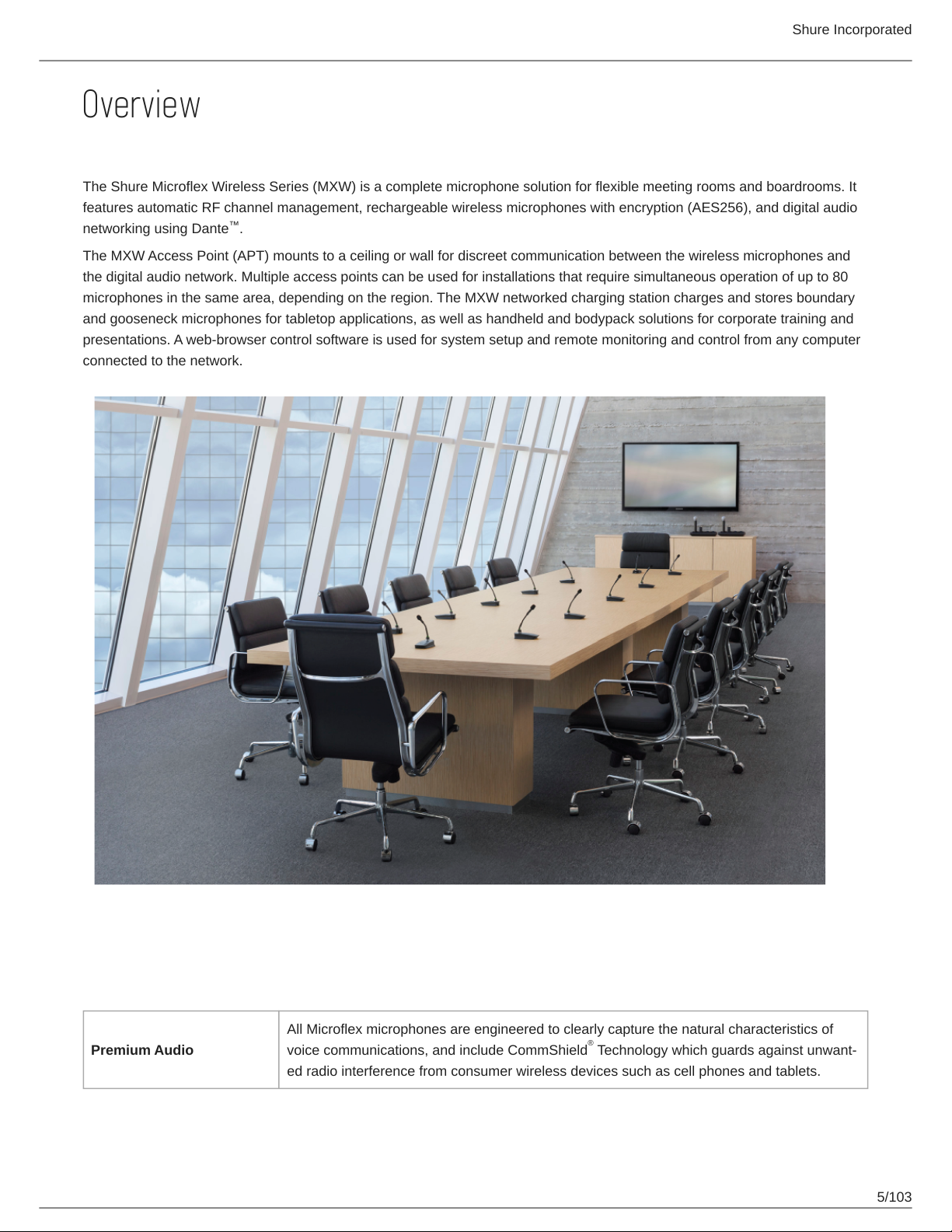
The Shure Microflex Wireless Series (MXW) is a complete microphone solution for flexible meeting rooms and boardrooms. It
features automatic RF channel management, rechargeable wireless microphones with encryption (AES256), and digital audio
networking using Dante .
The MXW Access Point (APT) mounts to a ceiling or wall for discreet communication between the wireless microphones and
the digital audio network. Multiple access points can be used for installations that require simultaneous operation of up to 80
microphones in the same area, depending on the region. The MXW networked charging station charges and stores boundary
and gooseneck microphones for tabletop applications, as well as handheld and bodypack solutions for corporate training and
presentations. A web-browser control software is used for system setup and remote monitoring and control from any computer
connected to the network.
™
Features
Legendary Shure Quality
All Microflex microphones are engineered to clearly capture the natural characteristics of
Premium Audio
voice communications, and include CommShield Technology which guards against unwant
ed radio interference from consumer wireless devices such as cell phones and tablets.
®
5/103
Page 6
Rechargeable Micro
phones
Shure Incorporated
Each MXW microphone is powered from a rechargeable Lithium-ion battery, which can be
charged at any time without removal from the microphone. Battery statistics are viewable
from the control software (battery runtime, time to full charge, charge cycle count and battery
capacity).
Discreet, Professional De
sign
Modern, lowprofile wireless microphone designs elegantly integrate into diverse AV environ
ments. By eliminating wires, MXW noticeably reduces clutter and provides professional ele
gance.
The MXW wireless link is encrypted using the Advanced Encryption Standard (AES-256), as
Encryption
specified by the US Government National Institute of Standards and Technology (NIST) pub
lication FIPS-197.
Advanced Networking and Control
Digital audio is carried over standard Ethernet using shielded Cat5e (or higher) cables. De
veloped with Dante technology by Audinate , MXW provides low latency, clock synchro
Digital Audio Networking
Automatic Frequency Co
ordination
nization, and high Quality-of-Service (QoS) to provide reliable audio transport. Digital audio
can coexist safely on the same network as IT and control data, or can be configured to use a
dedicated network.
The MXW Series uses automatic frequency coordination to quickly set up all of the micro
phones and achieve reliable, uninterrupted wireless communication. Microphones are as
signed to channels on an access point transceiver simply by arranging them in an associat
ed charging station and pressing the Link button. Multiple access point transceivers can
work together to support large installations or scalable rooms. Once Linked, the system au
tomatically scans the available RF spectrum and selects the best quality RF channels on
which to operate. Upon detecting interference, microphones automatically switch to the best
alternate RF channel determined during continuous background scanning.
tm
®
Remote Control and Moni
toring
BuiltIn RF Spectrum Scan
ner
Microflex Wireless components and software are compatible with Crestron, AMX, and other
programmable controllers. Components interconnect with teleconferencing equipment and
digital signal processors.
The MXW Wireless components transmit in unlicensed spectrum that may be used by other
wireless devices (in particular wireless phones and headsets) operating in the same area.
The MXW access point features an RF scanner to document the average and peak RF inter
ference. The data provides an accurate estimate for the number of MXW channels that can
be safely operated in the scanned area.
6/103
Page 7
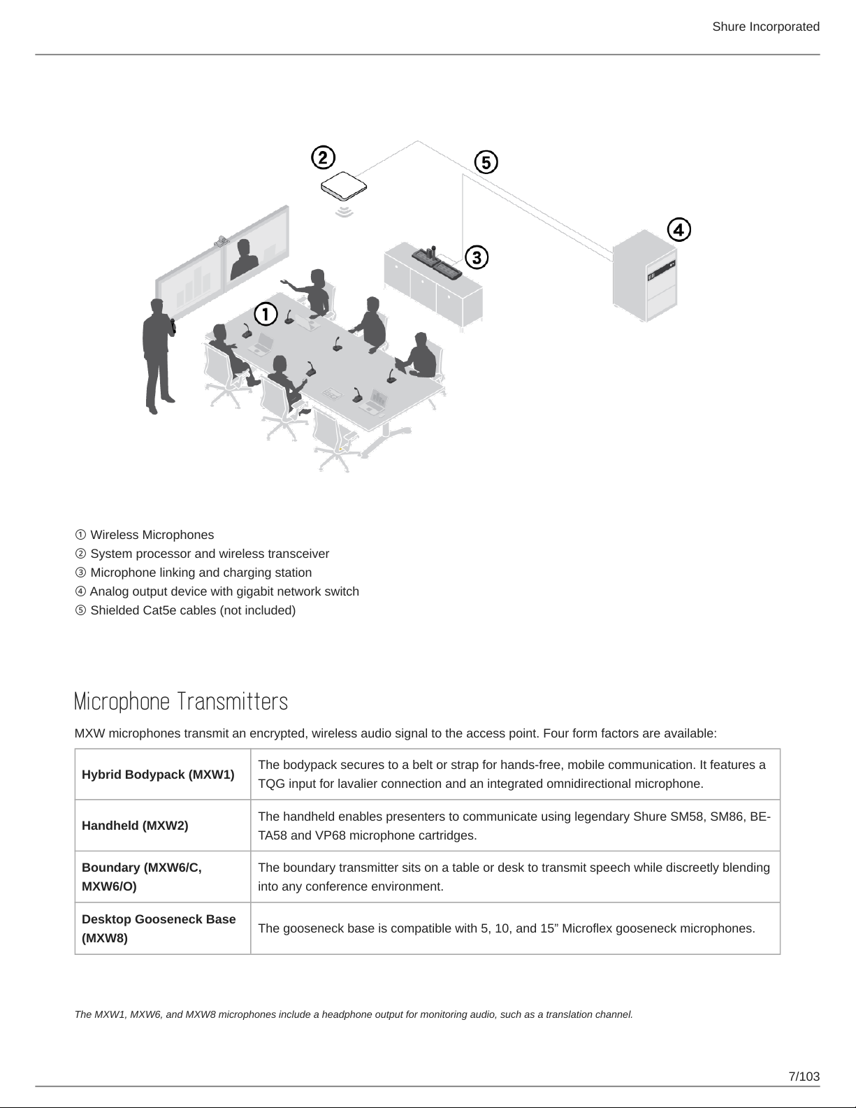
MXW Wireless System
Shure Incorporated
① Wireless Microphones
② System processor and wireless transceiver
③ Microphone linking and charging station
④ Analog output device with gigabit network switch
⑤ Shielded Cat5e cables (not included)
Components of the MXW System
Microphone Transmitters
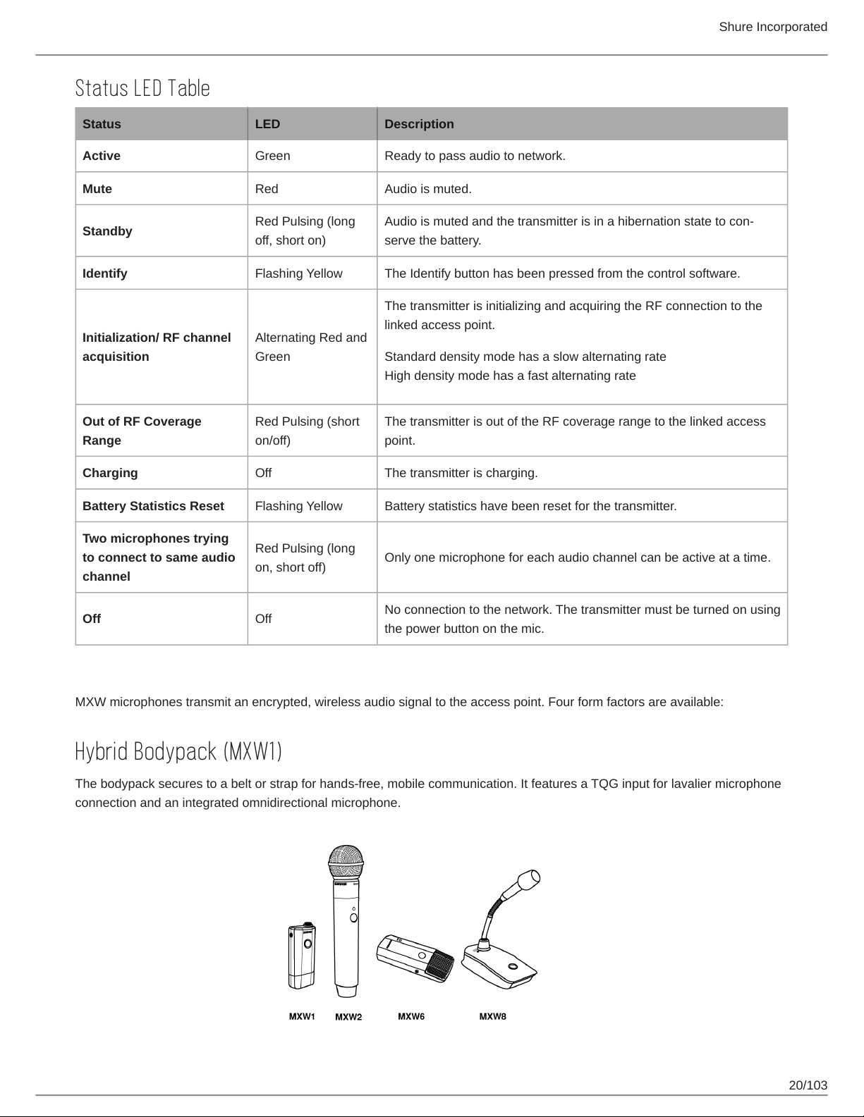
MXW microphones transmit an encrypted, wireless audio signal to the access point. Four form factors are available:
Hybrid Bodypack (MXW1)
Handheld (MXW2)
Boundary (MXW6/C,
MXW6/O)
Desktop Gooseneck Base
(MXW8)
The bodypack secures to a belt or strap for hands-free, mobile communication. It features a
TQG input for lavalier connection and an integrated omnidirectional microphone.
The handheld enables presenters to communicate using legendary Shure SM58, SM86, BE
TA58 and VP68 microphone cartridges.
The boundary transmitter sits on a table or desk to transmit speech while discreetly blending
into any conference environment.
The gooseneck base is compatible with 5, 10, and 15” Microflex gooseneck microphones.
The MXW1, MXW6, and MXW8 microphones include a headphone output for monitoring audio, such as a translation channel.
7/103
Page 8
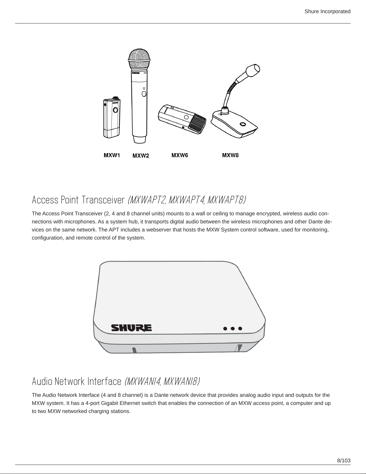
Shure Incorporated
Access Point Transceiver
The Access Point Transceiver (2, 4 and 8 channel units) mounts to a wall or ceiling to manage encrypted, wireless audio con
nections with microphones. As a system hub, it transports digital audio between the wireless microphones and other Dante de
vices on the same network. The APT includes a webserver that hosts the MXW System control software, used for monitoring,
configuration, and remote control of the system.
(MXWAPT2, MXWAPT4, MXWAPT8)
Audio Network Interface
The Audio Network Interface (4 and 8 channel) is a Dante network device that provides analog audio input and outputs for the
MXW system. It has a 4-port Gigabit Ethernet switch that enables the connection of an MXW access point, a computer and up
to two MXW networked charging stations.
(MXWANI4, MXWANI8)
8/103
Page 9
Shure Incorporated
Networked Charging Station
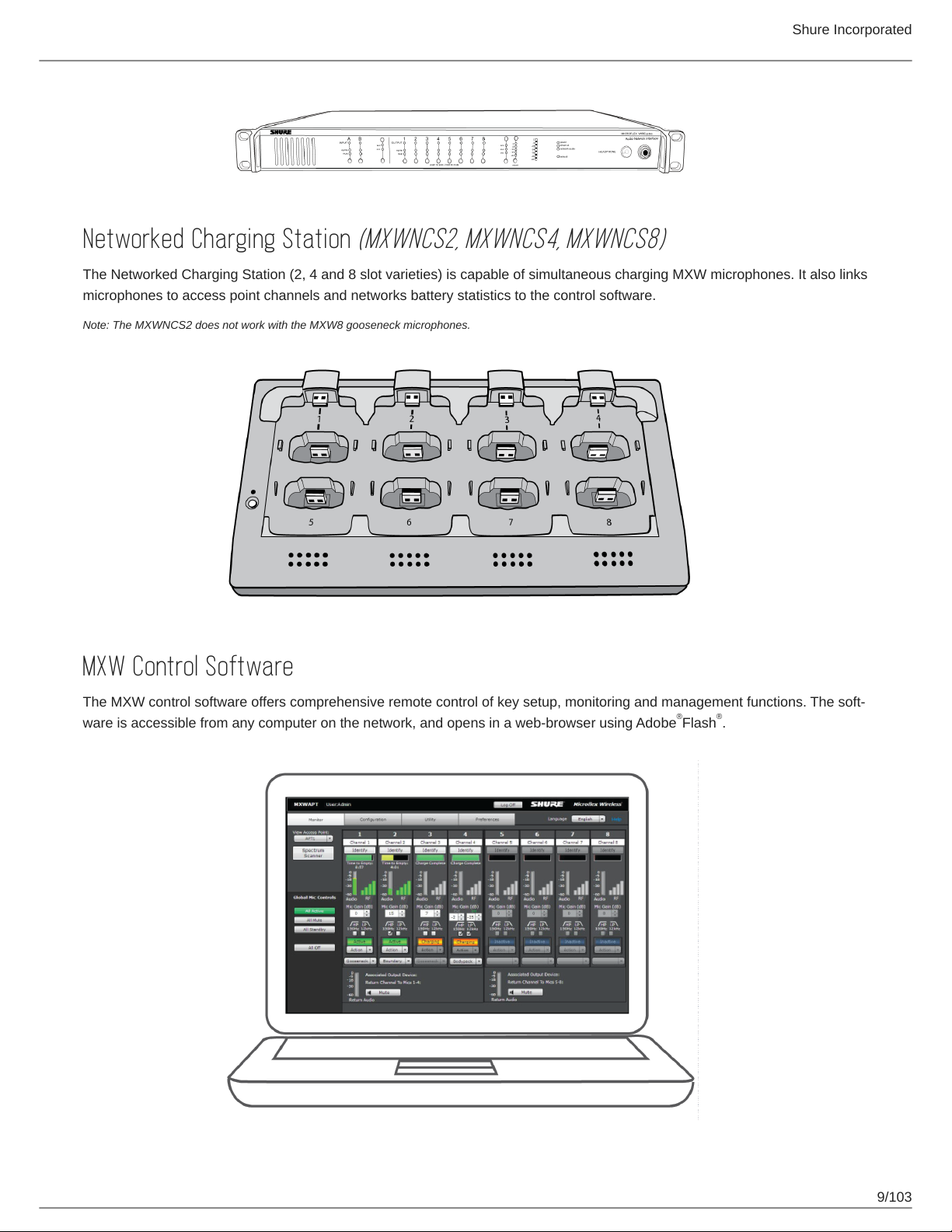
The Networked Charging Station (2, 4 and 8 slot varieties) is capable of simultaneous charging MXW microphones. It also links
microphones to access point channels and networks battery statistics to the control software.
Note: The MXWNCS2 does not work with the MXW8 gooseneck microphones.
(MXWNCS2, MXWNCS4, MXWNCS8)
MXW Control Software
The MXW control software offers comprehensive remote control of key setup, monitoring and management functions. The soft
ware is accessible from any computer on the network, and opens in a web-browser using Adobe Flash .
® ®
9/103
Page 10
Shure Incorporated
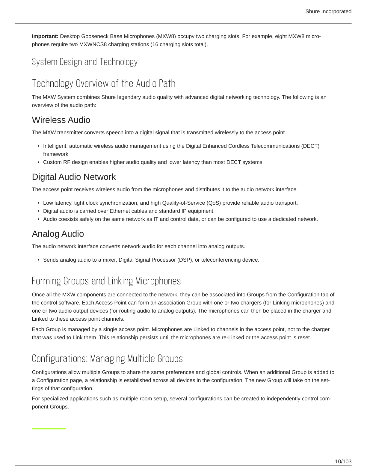
Important: Desktop Gooseneck Base Microphones (MXW8) occupy two charging slots. For example, eight MXW8 micro
phones require two MXWNCS8 charging stations (16 charging slots total).
System Design and Technology
Technology Overview of the Audio Path
The MXW System combines Shure legendary audio quality with advanced digital networking technology. The following is an
overview of the audio path:
Wireless Audio
The MXW transmitter converts speech into a digital signal that is transmitted wirelessly to the access point.
•
Intelligent, automatic wireless audio management using the Digital Enhanced Cordless Telecommunications (DECT)
framework
•
Custom RF design enables higher audio quality and lower latency than most DECT systems
Digital Audio Network
The access point receives wireless audio from the microphones and distributes it to the audio network interface.
•
Low latency, tight clock synchronization, and high Quality-of-Service (QoS) provide reliable audio transport.
•
Digital audio is carried over Ethernet cables and standard IP equipment.
•
Audio coexists safely on the same network as IT and control data, or can be configured to use a dedicated network.
Analog Audio
The audio network interface converts network audio for each channel into analog outputs.
•
Sends analog audio to a mixer, Digital Signal Processor (DSP), or teleconferencing device.
Forming Groups and Linking Microphones
Once all the MXW components are connected to the network, they can be associated into Groups from the Configuration tab of
the control software. Each Access Point can form an association Group with one or two chargers (for Linking microphones) and
one or two audio output devices (for routing audio to analog outputs). The microphones can then be placed in the charger and
Linked to these access point channels.
Each Group is managed by a single access point. Microphones are Linked to channels in the access point, not to the charger
that was used to Link them. This relationship persists until the microphones are re-Linked or the access point is reset.
Configurations: Managing Multiple Groups
Configurations allow multiple Groups to share the same preferences and global controls. When an additional Group is added to
a Configuration page, a relationship is established across all devices in the configuration. The new Group will take on the set
tings of that configuration.
For specialized applications such as multiple room setup, several configurations can be created to independently control com
ponent Groups.
10/103
Page 11

Shure Incorporated
Hardware Description
Audio Network Interface (ANI)
Front Panel
① Input Channels
Adds analog line- or aux-level signals to the digital network. When the device is associated to an MXW Group, inputs are
automatically routed to Linked microphone channels (Input A to channels 1-4; Input B to 5-8).
② Output Channels
Converts digital network audio to an analog output for each channel. When associated to an MXW group, access point
channels are automatically routed to the outputs of the ANI.
③ Channel Selector
Selects a channel to perform the following functions:
Action Function
Listen to that channel at the headphone jack
Single Press
Press and Hold (3 sec
onds)
Display and adjust the channel output level and attenuation
Monitor output signal on the level meter
Mute/unmute a channel. Mute is indicated by the mute LED.
④ Selected Channel LED
Illuminates when a channel is selected.
⑤ Signal Strength LED (sig/clip)
Indicates audio signal strength for each channel:
◦
Green = Normal
◦
Amber = Strong
◦
Red = Clipping (to eliminate clipping, attenuate the signal level at the audio source)
⑥ Mute LED
Illuminates red when the channel output is muted (hold its channel select button for 3 seconds). A muted channel is still
routed to the HEADPHONE jack for monitoring or troubleshooting.
11/103
Page 12
Shure Incorporated
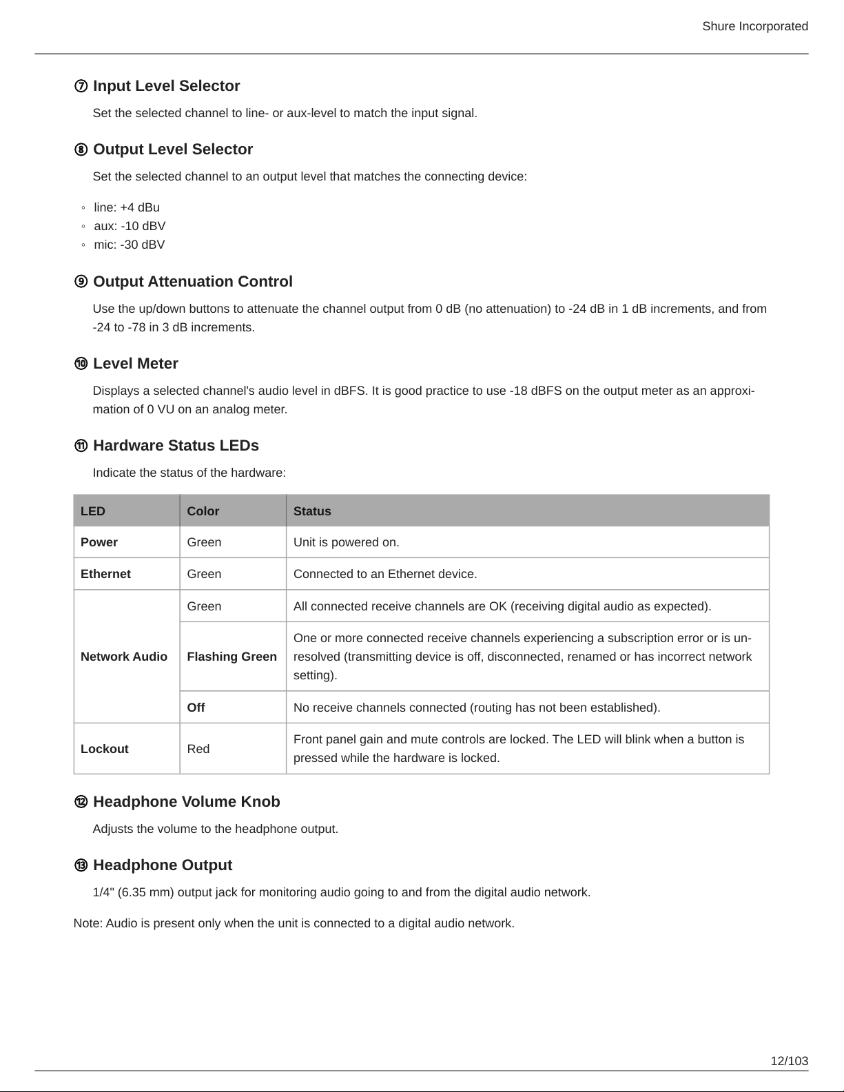
⑦ Input Level Selector
Set the selected channel to line- or aux-level to match the input signal.
⑧ Output Level Selector
Set the selected channel to an output level that matches the connecting device:
◦
line: +4 dBu
◦
aux: -10 dBV
◦
mic: -30 dBV
⑨ Output Attenuation Control
Use the up/down buttons to attenuate the channel output from 0 dB (no attenuation) to -24 dB in 1 dB increments, and from
-24 to -78 in 3 dB increments.
⑩ Level Meter
Displays a selected channel's audio level in dBFS. It is good practice to use 18 dBFS on the output meter as an approxi
mation of 0 VU on an analog meter.
⑪ Hardware Status LEDs
Indicate the status of the hardware:
LED Color Status
Power Green Unit is powered on.
Ethernet Green Connected to an Ethernet device.
Green All connected receive channels are OK (receiving digital audio as expected).
One or more connected receive channels experiencing a subscription error or is un
Network Audio
Lockout Red
Flashing Green
Off No receive channels connected (routing has not been established).
resolved (transmitting device is off, disconnected, renamed or has incorrect network
setting).
Front panel gain and mute controls are locked. The LED will blink when a button is
pressed while the hardware is locked.
⑫ Headphone Volume Knob
Adjusts the volume to the headphone output.
⑬ Headphone Output
1/4" (6.35 mm) output jack for monitoring audio going to and from the digital audio network.
Note: Audio is present only when the unit is connected to a digital audio network.
12/103
Page 13
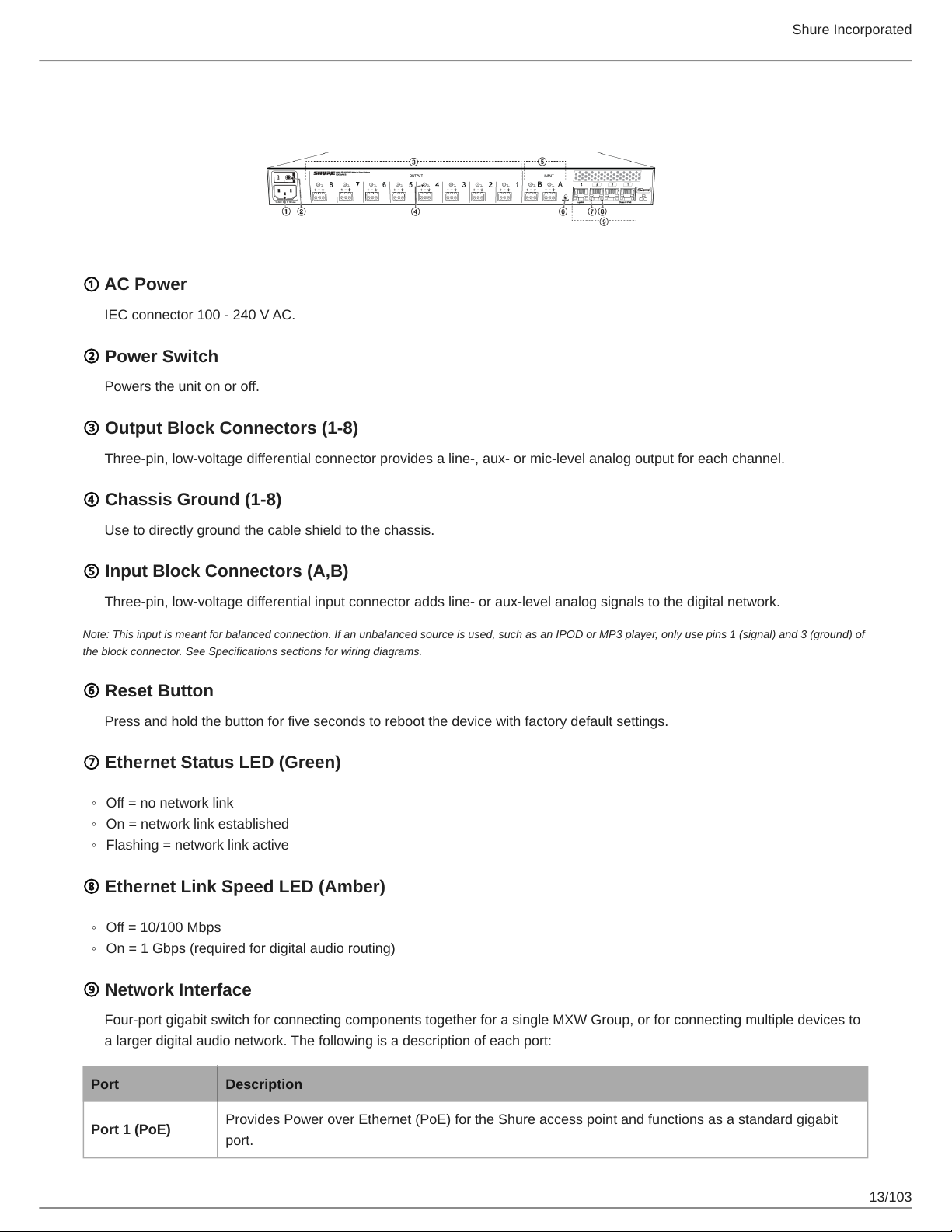
Back Panel
① AC Power
IEC connector 100 - 240 V AC.
② Power Switch
Powers the unit on or off.
③ Output Block Connectors (1-8)
Three-pin, low-voltage differential connector provides a line-, aux- or mic-level analog output for each channel.
Shure Incorporated
④ Chassis Ground (1-8)
Use to directly ground the cable shield to the chassis.
⑤ Input Block Connectors (A,B)
Three-pin, low-voltage differential input connector adds line- or aux-level analog signals to the digital network.
Note: This input is meant for balanced connection. If an unbalanced source is used, such as an IPOD or MP3 player, only use pins 1 (signal) and 3 (ground) of
the block connector. See Specifications sections for wiring diagrams.
⑥ Reset Button
Press and hold the button for five seconds to reboot the device with factory default settings.
⑦ Ethernet Status LED (Green)
◦
Off = no network link
◦
On = network link established
◦
Flashing = network link active
⑧ Ethernet Link Speed LED (Amber)
◦
Off = 10/100 Mbps
◦
On = 1 Gbps (required for digital audio routing)
⑨ Network Interface
Four-port gigabit switch for connecting components together for a single MXW Group, or for connecting multiple devices to
a larger digital audio network. The following is a description of each port:
Port Description
Port 1 (PoE)
Provides Power over Ethernet (PoE) for the Shure access point and functions as a standard gigabit
port.
13/103
Page 14
Port Description
Shure Incorporated
Ports 2 and 3
Port 4 (Uplink)
Standard gigabit ports enable the connection of another MXW network, additional MXWANIs, a
MXWNCS charging stations or an external control system.
Normal mode (default): this port functions the same as ports 2 and 3.
Uplink Mode: only transports control data. This mode blocks network audio and data for Shure Web
Discovery Application, Dante Controller and Dante Virtual Soundcard.
Access Point Transceiver (APT)
The access point transceiver is the hub of the audio signal flow and manages the RF stability of each microphone in the group.
The APT performs the following functions:
•
Receives and decrypts wireless audio signals from microphones in the group
•
Delivers the audio signal to the digital audio network and audio network interface (ANI)
•
Hosts an embedded web server that provides access to the control software used to manage the MXW system
•
Sends and receives control information (such as gain adjustment and link settings) between the components, MXW con
trol software and 3rd party controllers.
•
Transmits an encrypted audio signal to the microphone's headphone output for listening to translated audio or other exter
nal sources.
Model Variations
MXWAPT8 Eight-channel transceiver
MXWAPT4 Four-channel transceiver
MXWAPT2 Two-channel transceiver
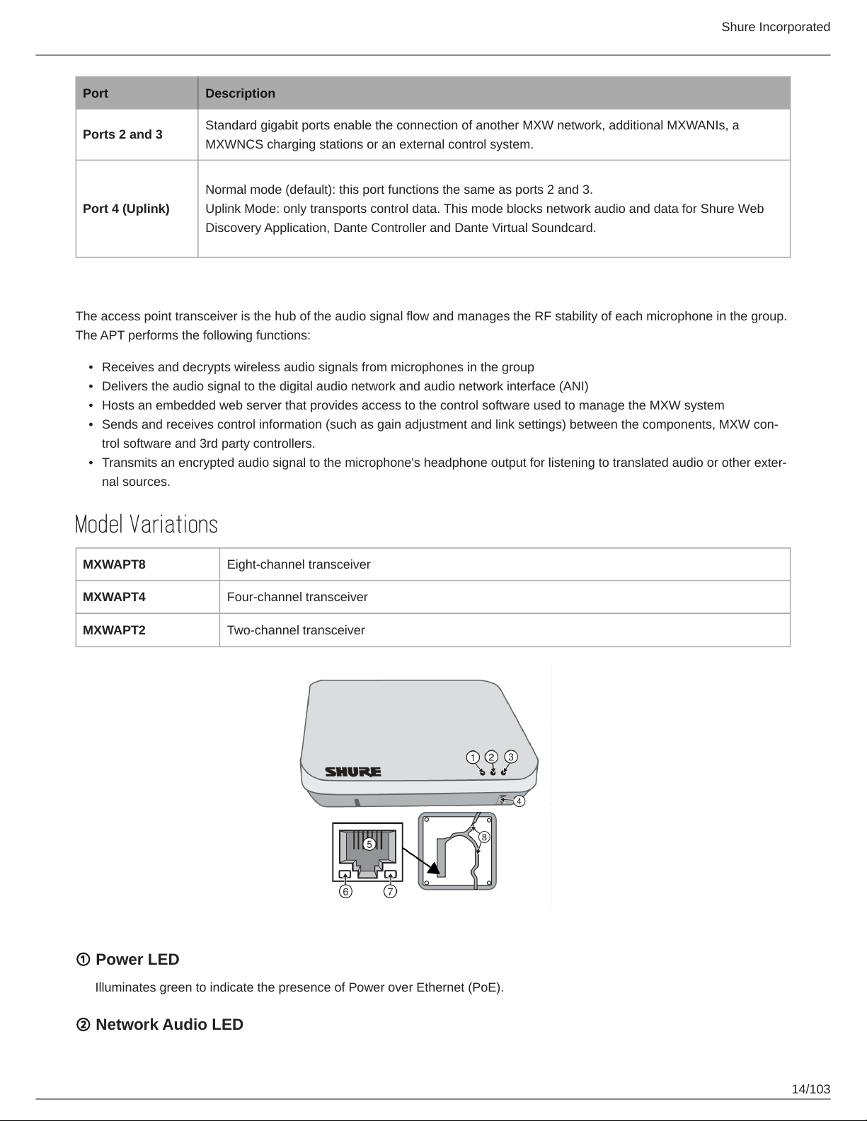
① Power LED
Illuminates green to indicate the presence of Power over Ethernet (PoE).
② Network Audio LED
14/103
Page 15
Color Status
Green All routed receive channels are OK (receiving digital audio as expected).
One or more connected receive channels experiencing a subscription error or is unresolved (trans
mitting device is off, disconnected, renamed or has incorrect network setting).
Flashing Green
Off No receive channels connected (routing has not been established).
Note: the network audio status can be monitored in detail from Dante Controller software.
Receiving an Identification signal from the control software (simultaneous flash with Link Status
LED).
The device is performing a spectrum scan (alternating flash with Link Status LED).
Clock synchronization problem.
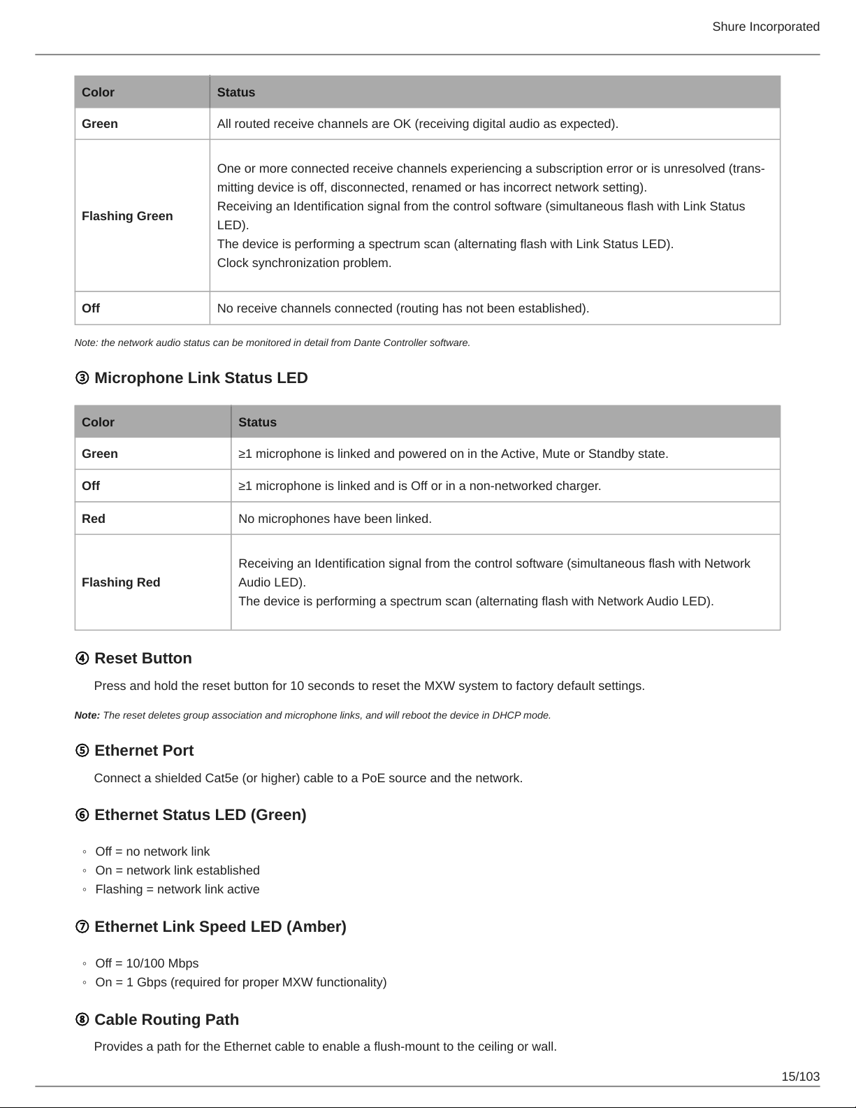
③ Microphone Link Status LED
Color Status
Shure Incorporated
Green ≥1 microphone is linked and powered on in the Active, Mute or Standby state.
Off ≥1 microphone is linked and is Off or in a nonnetworked charger.
Red No microphones have been linked.
Receiving an Identification signal from the control software (simultaneous flash with Network
Flashing Red
Audio LED).
The device is performing a spectrum scan (alternating flash with Network Audio LED).
④ Reset Button
Press and hold the reset button for 10 seconds to reset the MXW system to factory default settings.
Note: The reset deletes group association and microphone links, and will reboot the device in DHCP mode.
⑤ Ethernet Port
Connect a shielded Cat5e (or higher) cable to a PoE source and the network.
⑥ Ethernet Status LED (Green)
◦
Off = no network link
◦
On = network link established
◦
Flashing = network link active
⑦ Ethernet Link Speed LED (Amber)
◦
Off = 10/100 Mbps
◦
On = 1 Gbps (required for proper MXW functionality)
⑧ Cable Routing Path
Provides a path for the Ethernet cable to enable a flush-mount to the ceiling or wall.
15/103
Page 16
Shure Incorporated
Directional Antennas
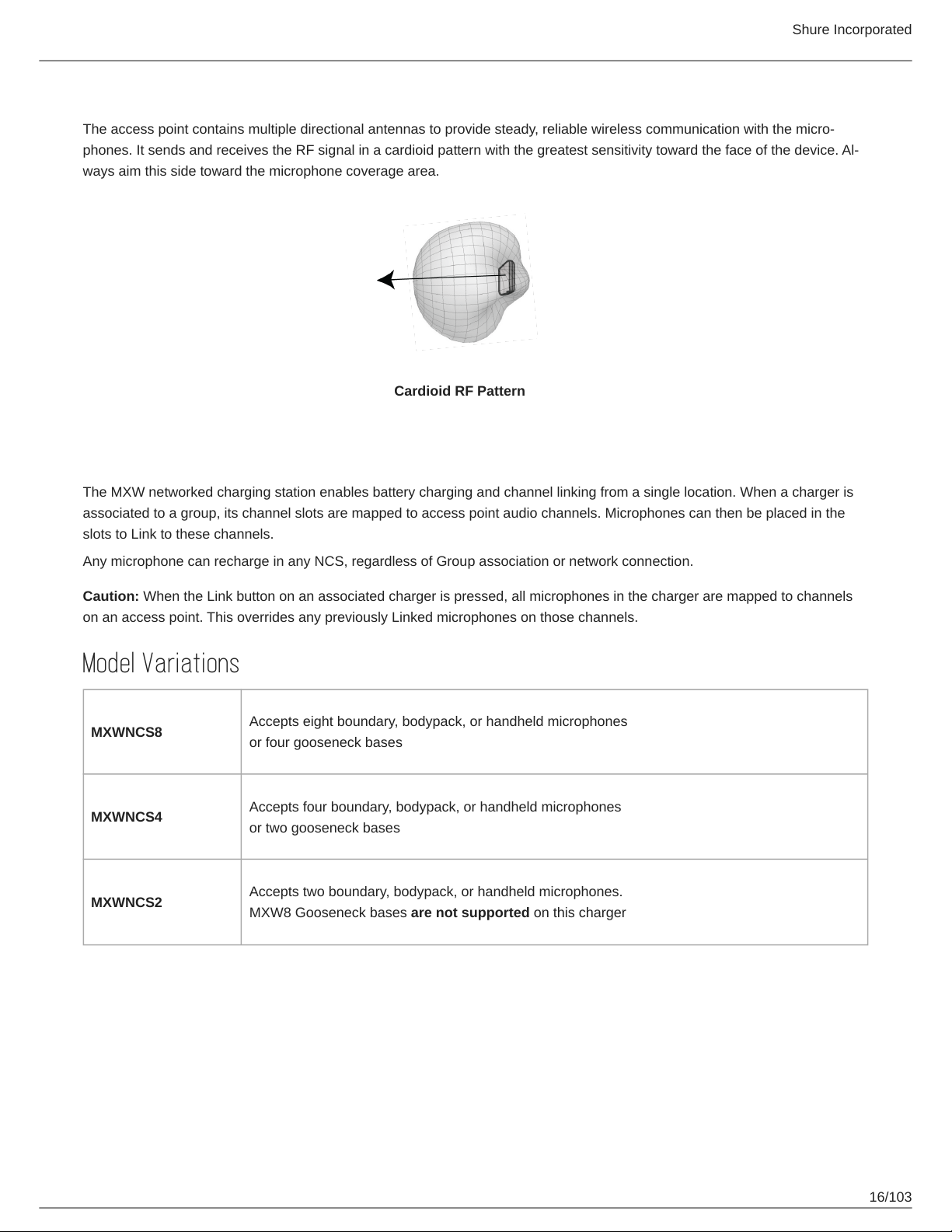
The access point contains multiple directional antennas to provide steady, reliable wireless communication with the micro
phones. It sends and receives the RF signal in a cardioid pattern with the greatest sensitivity toward the face of the device. Al
ways aim this side toward the microphone coverage area.
Cardioid RF Pattern
Networked Charger (NCS)
The MXW networked charging station enables battery charging and channel linking from a single location. When a charger is
associated to a group, its channel slots are mapped to access point audio channels. Microphones can then be placed in the
slots to Link to these channels.
Any microphone can recharge in any NCS, regardless of Group association or network connection.
Caution: When the Link button on an associated charger is pressed, all microphones in the charger are mapped to channels
on an access point. This overrides any previously Linked microphones on those channels.
Model Variations
MXWNCS8
MXWNCS4
MXWNCS2
Accepts eight boundary, bodypack, or handheld microphones
or four gooseneck bases
Accepts four boundary, bodypack, or handheld microphones
or two gooseneck bases
Accepts two boundary, bodypack, or handheld microphones.
MXW8 Gooseneck bases are not supported on this charger
16/103
Page 17
Shure Incorporated
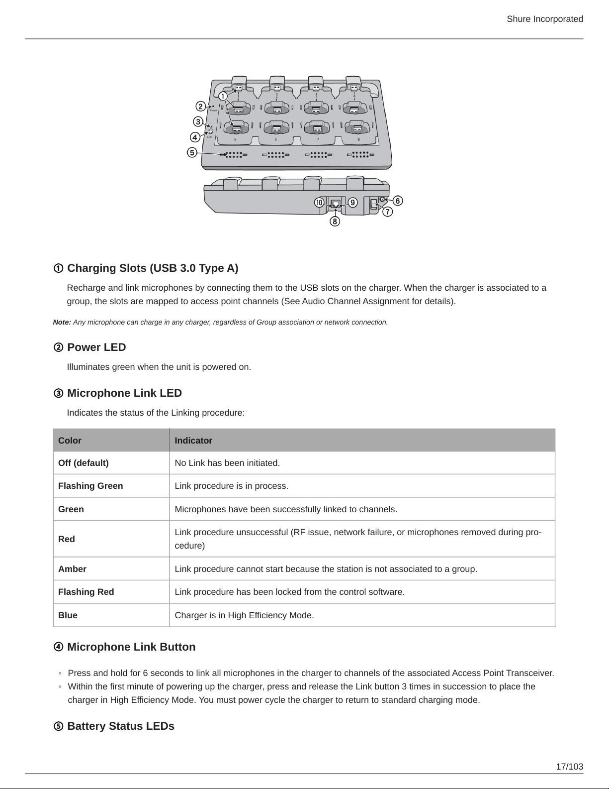
① Charging Slots (USB 3.0 Type A)
Recharge and link microphones by connecting them to the USB slots on the charger. When the charger is associated to a
group, the slots are mapped to access point channels (See Audio Channel Assignment for details).
Note: Any microphone can charge in any charger, regardless of Group association or network connection.
② Power LED
Illuminates green when the unit is powered on.
③ Microphone Link LED
Indicates the status of the Linking procedure:
Color Indicator
Off (default) No Link has been initiated.
Flashing Green Link procedure is in process.
Green Microphones have been successfully linked to channels.
Red
Amber Link procedure cannot start because the station is not associated to a group.
Flashing Red Link procedure has been locked from the control software.
Link procedure unsuccessful (RF issue, network failure, or microphones removed during pro
cedure)
Blue Charger is in High Efficiency Mode.
④ Microphone Link Button
◦
Press and hold for 6 seconds to link all microphones in the charger to channels of the associated Access Point Transceiver.
◦
Within the first minute of powering up the charger, press and release the Link button 3 times in succession to place the
charger in High Efficiency Mode. You must power cycle the charger to return to standard charging mode.
⑤ Battery Status LEDs
17/103
Page 18
Shure Incorporated
Monitors the charge status of the connected microphone in increments of <10, 10, 25, 50, 75, 100% (see Batteries for more
detail). Additionally, the five LEDs flash for several seconds when the microphone has been successfully linked to the chan
nel.
⑥ Locking DC Power Supply
Secures the PS60 power supply to the input jack of the station.
⑦ Power Switch
Powers the unit on or off.
⑧ Ethernet Port
Connects to the MXW System network through an MXW Audio Network Interface or a switch using an Ethernet cable.
⑨ Ethernet Status LED (Green)
◦
Off = no network link.
◦
On = network link established.
◦
Flashing = network link active.
⑩ Ethernet Link Speed LED (Amber)
◦
Off = 10 Mbps
◦
On = 100 Mbps
Connecting Microphones
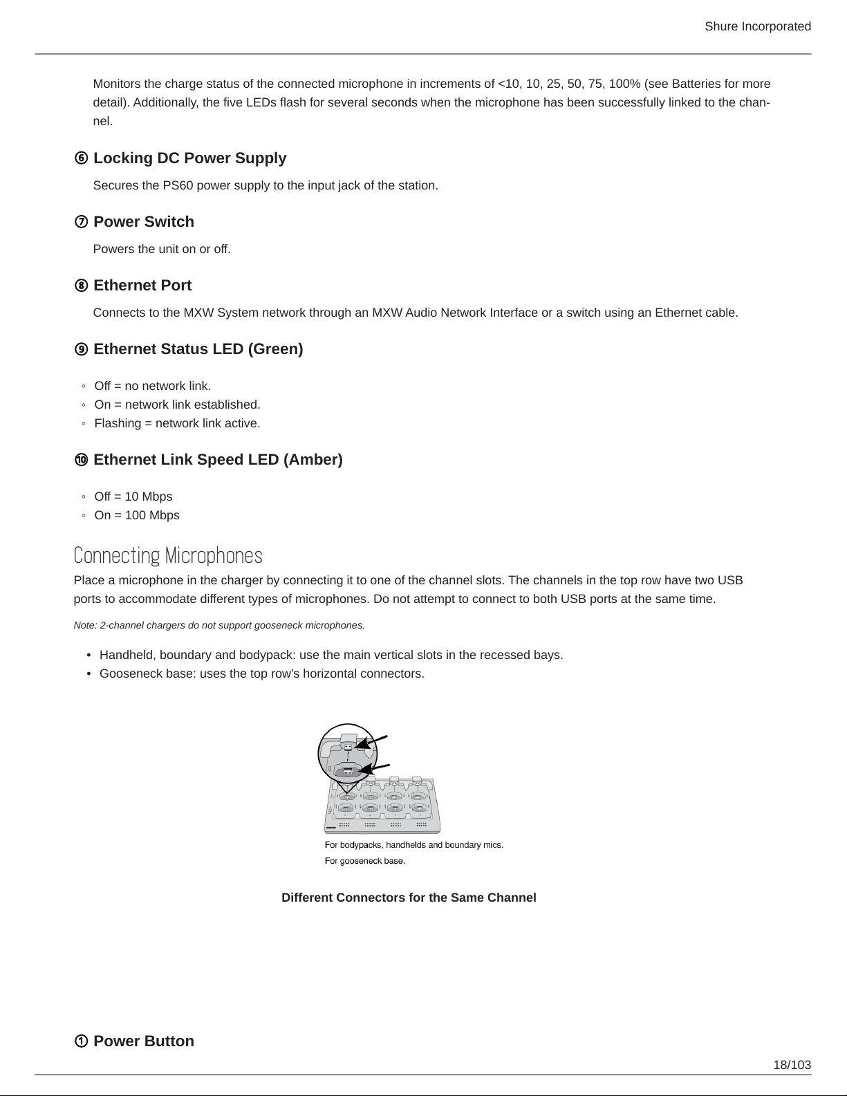
Place a microphone in the charger by connecting it to one of the channel slots. The channels in the top row have two USB
ports to accommodate different types of microphones. Do not attempt to connect to both USB ports at the same time.
Note: 2-channel chargers do not support gooseneck microphones.
•
Handheld, boundary and bodypack: use the main vertical slots in the recessed bays.
•
Gooseneck base: uses the top row's horizontal connectors.
Different Connectors for the Same Channel
Microphone Transmitters
Description
① Power Button
18/103
Page 19
Shure Incorporated
MXW6, MXW8: Press and hold the dedicated power button for three seconds to turn the transmitter on or off.
MXW1, MXW2: Press and hold the Mute/Active button for five seconds to turn the transmitter on or off.
② Mute/Active Button
Changes the audio status from Active to Mute, or Mute to Active. The button behavior for each transmitter type can be set
independently from the Preferences tab. The following describes the function of each setting:
◦
Toggle: Press and release the button to change the status to Active or Mute.
◦
Push-to-talk: Hold button to pass audio.
◦
Push-to-mute: Hold button to mute the audio.
◦
Disabled: The button does not affect the audio.
③ Status LED
Indicates the transmitter's status. The color indicators for Mute and Active can be customized from the Preferences tab. See
the Status LED table for the default LED behavior for MXW transmitters except the gooseneck light-ring models (MX405R/
410R/415R).
④ Low Battery LED (Gooseneck and Boundary only)
Color Status
Off <5% battery runtime remains
Solid Red >5% battery runtime remains
⑤ Earphone Jack
1/8" (3.5 mm) jack for monitoring a return channel signal, such as translated audio. This audio is automatically routed from
the input(s) of the Audio Network Interface (Input A to channels 1 - 4; Input B to channels 5 - 8).
Note: Not featured on the MXW2 handheld transmitter.
⑥ Charge Connector (USB 3.0 Type A)
Connects to the NCS charger slot or to the USB Charger.
⑦ Handheld Cartridge
MXW2 transmitter is compatible with the following cartridge types: SM58, Beta 58, SM86, VP68.
⑧ Gooseneck Microphone
The gooseneck base is compatible with 5, 10, and 15” Microflex gooseneck microphones.
⑧ TQG Connector
The MXW hybrid bodypack has a TQG connector for an external lavalier or headset microphone.
⑩ Internal Microphone
The bodypack transmitter has an internal, omnidirectional microphone that can be set to automatically engage when not
connected to a lavalier microphone.
19/103
Page 20
Status LED Table
Status LED Description
Active Green Ready to pass audio to network.
Mute Red Audio is muted.
Shure Incorporated
Standby
Identify Flashing Yellow The Identify button has been pressed from the control software.
Initialization/ RF channel
acquisition
Out of RF Coverage
Range
Charging Off The transmitter is charging.
Battery Statistics Reset Flashing Yellow Battery statistics have been reset for the transmitter.
Two microphones trying
to connect to same audio
channel
Off Off
Red Pulsing (long
off, short on)
Alternating Red and
Green
Red Pulsing (short
on/off)
Red Pulsing (long
on, short off)
Audio is muted and the transmitter is in a hibernation state to con
serve the battery.
The transmitter is initializing and acquiring the RF connection to the
linked access point.
Standard density mode has a slow alternating rate
High density mode has a fast alternating rate
The transmitter is out of the RF coverage range to the linked access
point.
Only one microphone for each audio channel can be active at a time.
No connection to the network. The transmitter must be turned on using
the power button on the mic.
Microphone Transmitters
MXW microphones transmit an encrypted, wireless audio signal to the access point. Four form factors are available:
Hybrid Bodypack (MXW1)
The bodypack secures to a belt or strap for hands-free, mobile communication. It features a TQG input for lavalier microphone
connection and an integrated omnidirectional microphone.
20/103
Page 21
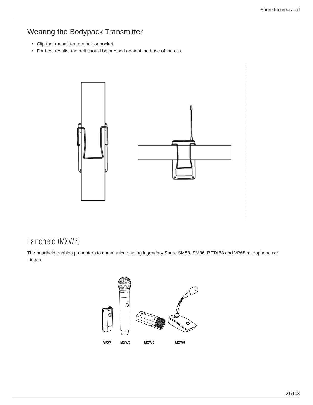
Wearing the Bodypack Transmitter
•
Clip the transmitter to a belt or pocket.
•
For best results, the belt should be pressed against the base of the clip.
Shure Incorporated
Handheld (MXW2)
The handheld enables presenters to communicate using legendary Shure SM58, SM86, BETA58 and VP68 microphone car
tridges.
21/103
Page 22
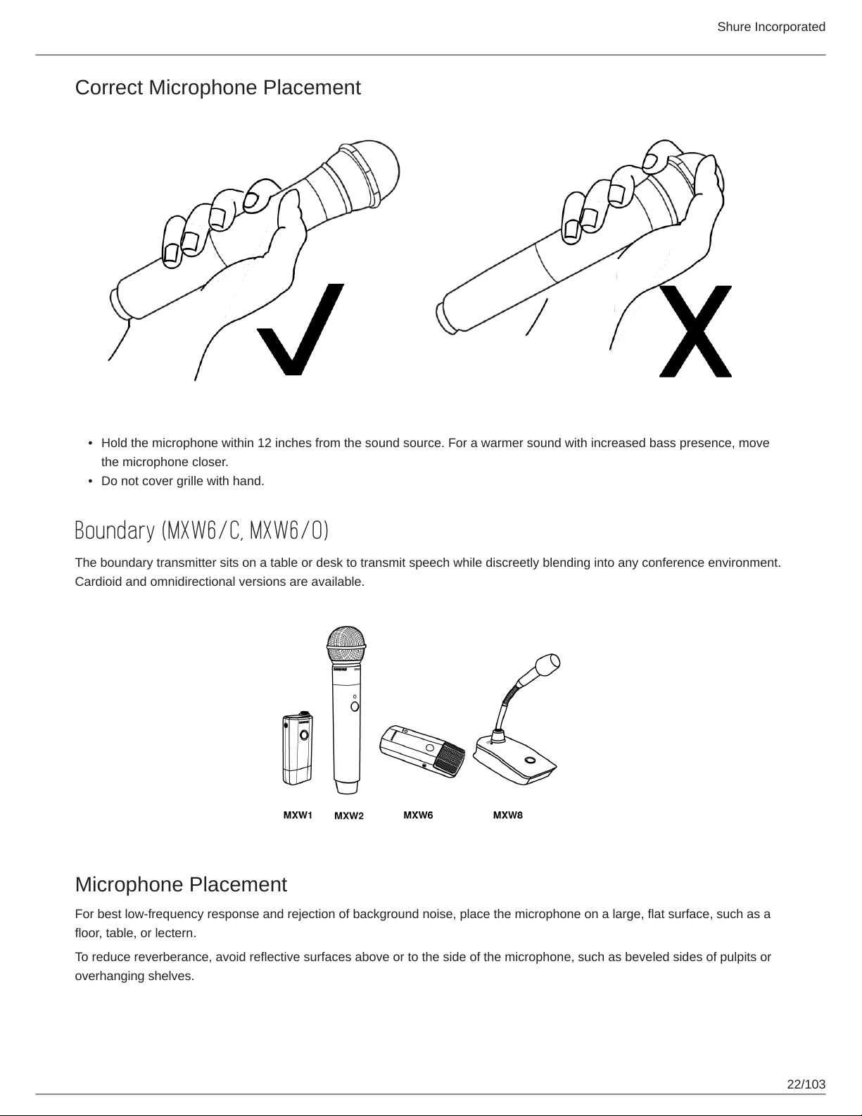
Correct Microphone Placement
Shure Incorporated
•
Hold the microphone within 12 inches from the sound source. For a warmer sound with increased bass presence, move
the microphone closer.
•
Do not cover grille with hand.
Boundary (MXW6/C, MXW6/O)
The boundary transmitter sits on a table or desk to transmit speech while discreetly blending into any conference environment.
Cardioid and omnidirectional versions are available.
Microphone Placement
For best low-frequency response and rejection of background noise, place the microphone on a large, flat surface, such as a
floor, table, or lectern.
To reduce reverberance, avoid reflective surfaces above or to the side of the microphone, such as beveled sides of pulpits or
overhanging shelves.
22/103
Page 23
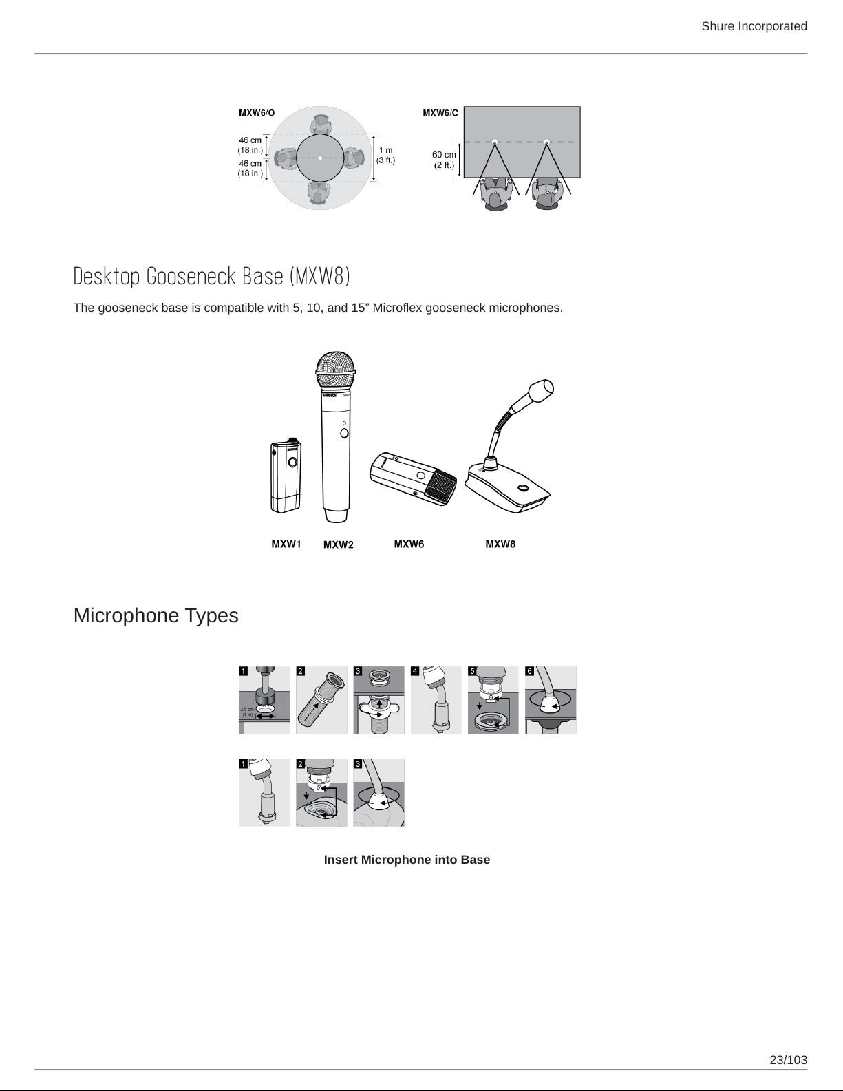
Desktop Gooseneck Base (MXW8)
The gooseneck base is compatible with 5, 10, and 15” Microflex gooseneck microphones.
Shure Incorporated
Microphone Types
Insert Microphone into Base
23/103
Page 24
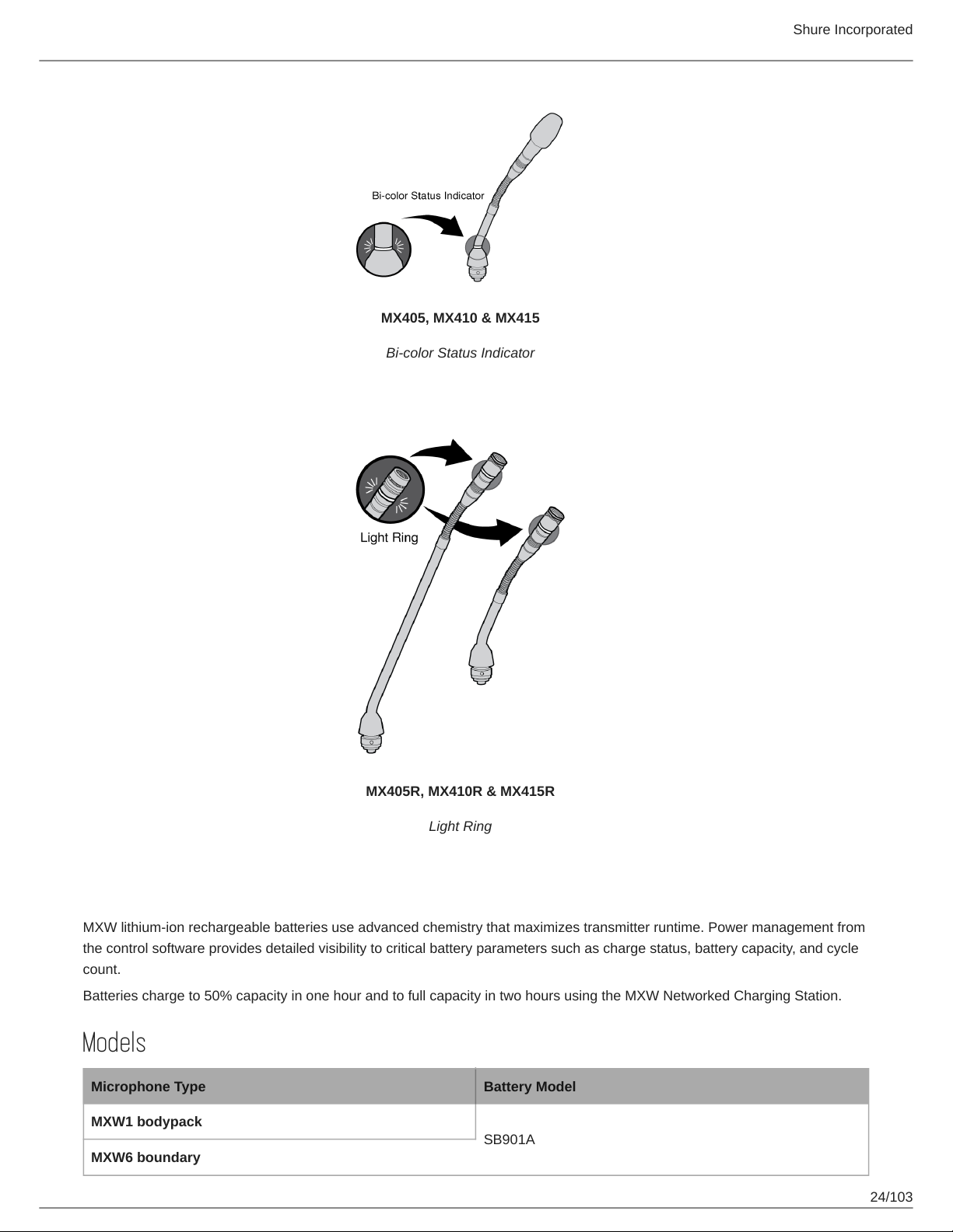
MX405, MX410 & MX415
Bi-color Status Indicator
Shure Incorporated
MX405R, MX410R & MX415R
Light Ring
Rechargeable Batteries
MXW lithium-ion rechargeable batteries use advanced chemistry that maximizes transmitter runtime. Power management from
the control software provides detailed visibility to critical battery parameters such as charge status, battery capacity, and cycle
count.
Batteries charge to 50% capacity in one hour and to full capacity in two hours using the MXW Networked Charging Station.
Models
Microphone Type Battery Model
MXW1 bodypack
SB901A
MXW6 boundary
24/103
Page 25
Shure Incorporated
Microphone Type Battery Model
MXW8 gooseneck base
MXW2 handheld SB902A
Networked Charging Station (NCS)
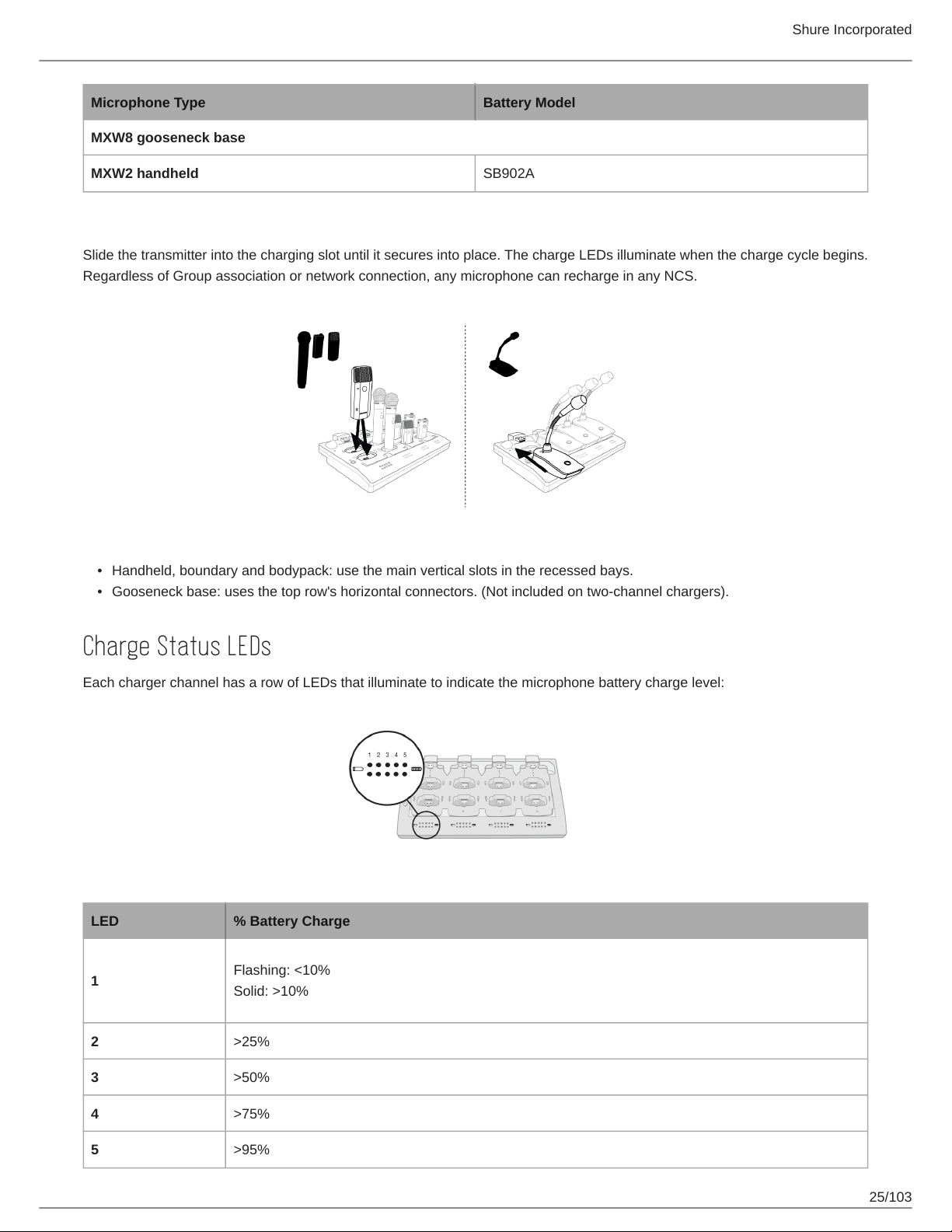
Slide the transmitter into the charging slot until it secures into place. The charge LEDs illuminate when the charge cycle begins.
Regardless of Group association or network connection, any microphone can recharge in any NCS.
•
Handheld, boundary and bodypack: use the main vertical slots in the recessed bays.
•
Gooseneck base: uses the top row's horizontal connectors. (Not included on two-channel chargers).
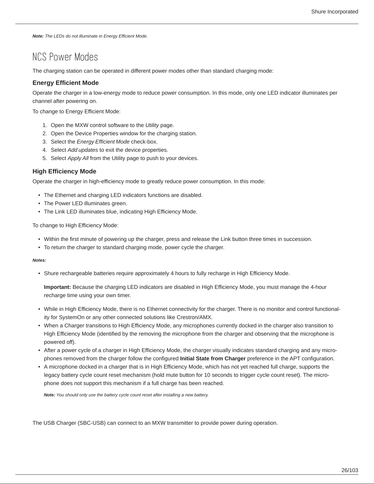
Charge Status LEDs
Each charger channel has a row of LEDs that illuminate to indicate the microphone battery charge level:
LED % Battery Charge
1
Flashing: <10%
Solid: >10%
2 >25%
3 >50%
4 >75%
5 >95%
25/103
Page 26
Shure Incorporated
Note: The LEDs do not illuminate in Energy Efficient Mode.
NCS Power Modes
The charging station can be operated in different power modes other than standard charging mode:
Energy Efficient Mode
Operate the charger in a low-energy mode to reduce power consumption. In this mode, only one LED indicator illuminates per
channel after powering on.
To change to Energy Efficient Mode:
1.
Open the MXW control software to the Utility page.
2.
Open the Device Properties window for the charging station.
3.
Select the Energy Efficient Mode check-box.
4.
Select Add updates to exit the device properties.
5.
Select Apply All from the Utility page to push to your devices.
High Efficiency Mode
Operate the charger in high-efficiency mode to greatly reduce power consumption. In this mode:
•
The Ethernet and charging LED indicators functions are disabled.
•
The Power LED illuminates green.
•
The Link LED illuminates blue, indicating High Efficiency Mode.
To change to High Efficiency Mode:
•
Within the first minute of powering up the charger, press and release the Link button three times in succession.
•
To return the charger to standard charging mode, power cycle the charger.
Notes:
•
Shure rechargeable batteries require approximately 4 hours to fully recharge in High Efficiency Mode.
Important: Because the charging LED indicators are disabled in High Efficiency Mode, you must manage the 4-hour
recharge time using your own timer.
•
While in High Efficiency Mode, there is no Ethernet connectivity for the charger. There is no monitor and control functional
ity for SystemOn or any other connected solutions like Crestron/AMX.
•
When a Charger transitions to High Efficiency Mode, any microphones currently docked in the charger also transition to
High Efficiency Mode (identified by the removing the microphone from the charger and observing that the microphone is
powered off).
•
After a power cycle of a charger in High Efficiency Mode, the charger visually indicates standard charging and any micro
phones removed from the charger follow the configured Initial State from Charger preference in the APT configuration.
•
A microphone docked in a charger that is in High Efficiency Mode, which has not yet reached full charge, supports the
legacy battery cycle count reset mechanism (hold mute button for 10 seconds to trigger cycle count reset). The micro
phone does not support this mechanism if a full charge has been reached.
Note: You should only use the battery cycle count reset after installing a new battery.
USB Charger
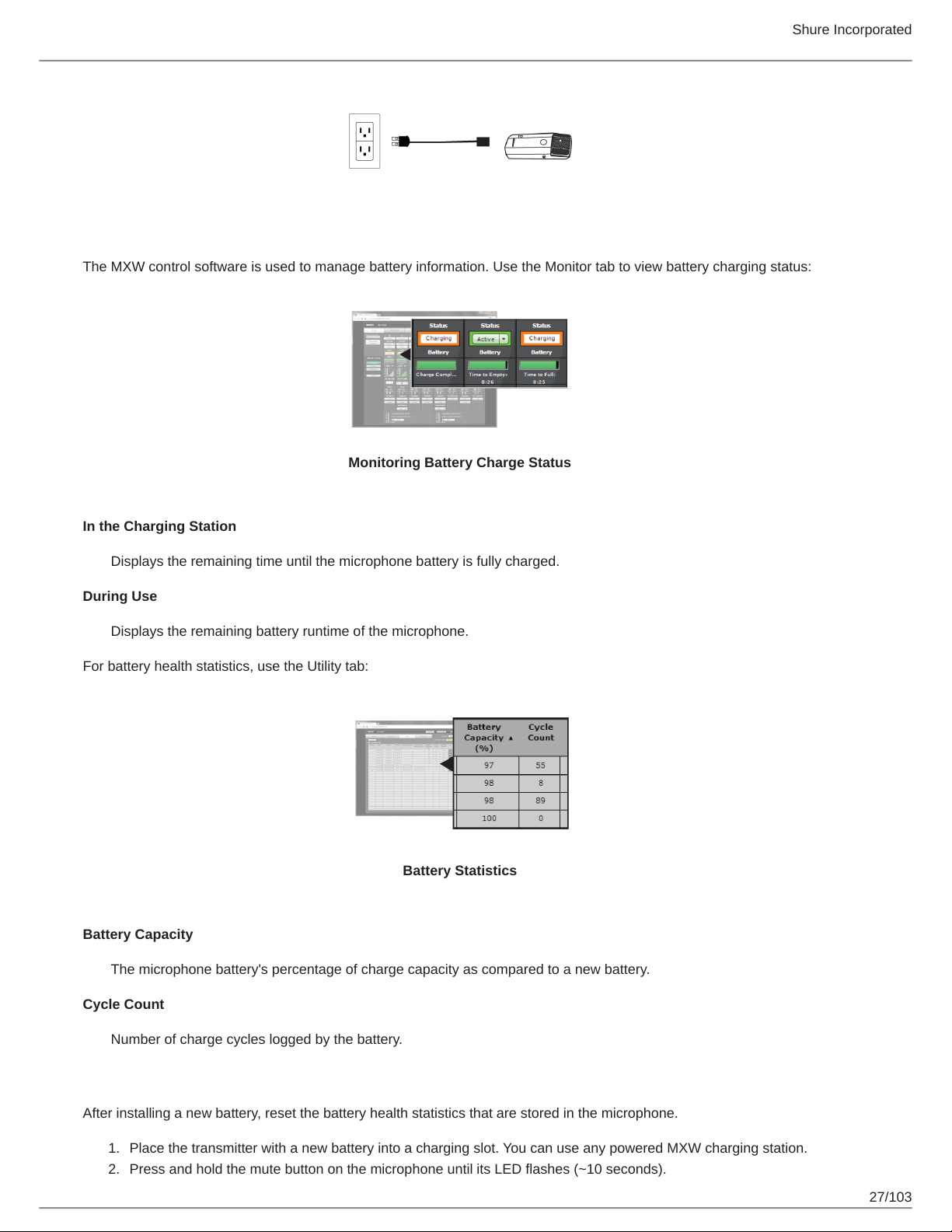
The USB Charger (SBC-USB) can connect to an MXW transmitter to provide power during operation.
26/103
Page 27
Shure Incorporated
Battery Statistics on Control Software
The MXW control software is used to manage battery information. Use the Monitor tab to view battery charging status:
Monitoring Battery Charge Status
In the Charging Station
Displays the remaining time until the microphone battery is fully charged.
During Use
Displays the remaining battery runtime of the microphone.
For battery health statistics, use the Utility tab:
Battery Statistics
Battery Capacity
The microphone battery's percentage of charge capacity as compared to a new battery.
Cycle Count
Number of charge cycles logged by the battery.
Reset the Microphone Battery Statistics
After installing a new battery, reset the battery health statistics that are stored in the microphone.
1.
Place the transmitter with a new battery into a charging slot. You can use any powered MXW charging station.
2.
Press and hold the mute button on the microphone until its LED flashes (~10 seconds).
27/103
Page 28
Shure Incorporated
Caution: Securely hold the microphone while pressing the button to avoid damaging the USB ports on the charging
station.
Maximizing Battery Life
While the rechargeable LiIon batteries for MXW transmitters are designed to last up to 9 hours on a charge, variance in bat
tery health and use-case may result in significant differences in battery runtime. Specifically, consistency and overall runtime
decrease with the number of charge cycles. Battery health of 80% or less is an indicator that a battery is nearing or at the end
of its designated life cycle and should be replaced. Health percentage and number of charge cycles are available from MXW
control software > Utility tab.
The MXW system's secondary link slots allow you to prepare alternate microphones to swap in if battery levels get low, to en
sure variable battery runtime does not cause audio interruptions. However, the following system adjustments can help get the
most runtime out of your batteries.
External LED Control
Having LEDs constantly indicate the microphone state can use a significant amount of battery power. Setting transmitters to
External LED Control disables the built-in LED except when activated by external commands via the TCPI (third-party control
interface). Maximize battery runtime by disabling the LED completely, or by setting the LED to only indicate when the micro
phone is not in its usual use state.
LED control is set from MXW control software > Preferences tab.
High Density Mode
High Density (HD) mode reallocates system resources to create additional channels when needed. In applications where laten
cy, back-channel audio monitoring, and filter control aren't major considerations, switching to HD mode can also provide up to
an hour of additional battery runtime.
Density mode is set from MXW control software > Utility tab > [desired APT] > Edit.
Use-Case Scenarios
To estimate runtime on older batteries, find your microphone and the conditions that most closely match your setup. Runtime
(hours) was calculated using batteries at 80% health.
System Settings Runtime (hours)
LED Density Mode MXW1 MXW2 MXW6 MXW8
External HD 8 15 8 8
External SD 7 14 7 7
Internal HD 7 14 8 7
Internal SD 6 12 7 6
Tip: If additional runtime is needed, make sure the RF Power is at the lowest setting for the size of the room. RF power is set
from MXW control software > Preferences tab.
Battery Replacement
Lithium Ion Batteries experience a linear reduction in capacity. Shure recommends establishing a battery replacement sched
ule customized to the client requirements and replacing batteries when the capacity is no longer acceptable.
28/103
Page 29
Shure Incorporated
Important: After installing a new battery, reset the battery health statistics that are stored in the microphone following the steps
in Reset the Microphone Battery Statistics in the previous section.
MXW1, MXW6, MXW8 Battery Replacement
1.
Unscrew and open the battery door on the bottom of the transmitter.
2.
Remove battery by gently disconnecting the battery connector from the transmitter.
3.
Connect the replacement battery's connector to the transmitter.
4.
Replace the battery with the label facing out.
5.
Close the door and tighten the screw.
6.
Dispose of batteries properly. Check with your local vendor for proper disposal of used batteries.
MXW2 Battery Replacement
1.
Unscrew the two screws at the bottom of the transmitter handle.
2.
Unscrew and remove the microphone head.
3.
Remove the retention clip and gently pull out the battery frame.
4.
Unscrew the three screws that fasten the battery door to the frame. Remove the battery door.
5.
Replace the old battery with a new one.
6.
Replace the battery door and tighten the screws.
7.
Gently slide the battery frame back into the transmitter.
8.
Replace the retention clip to secure the battery frame in the transmitter.
9.
Replace the microphone head. Make sure it is secure.
10.
Replace the two screws on the bottom of the transmitter handle.
11.
Dispose of batteries properly. Check with your local vendor for proper disposal of used batteries.
Installation
Additional Equipment
Network Cables
Audio Cables
Use shielded Cat5e (or higher) Ethernet cables, limiting cable runs to 100 meters maximum
between network devices.
Reference the hardware kit user guide supplied with the MXW Audio Network Interface to
assemble audio cables to the connectors.
29/103
Page 30
Gigabit DHCP Router (sys
tems with >1 APT)
Shure Incorporated
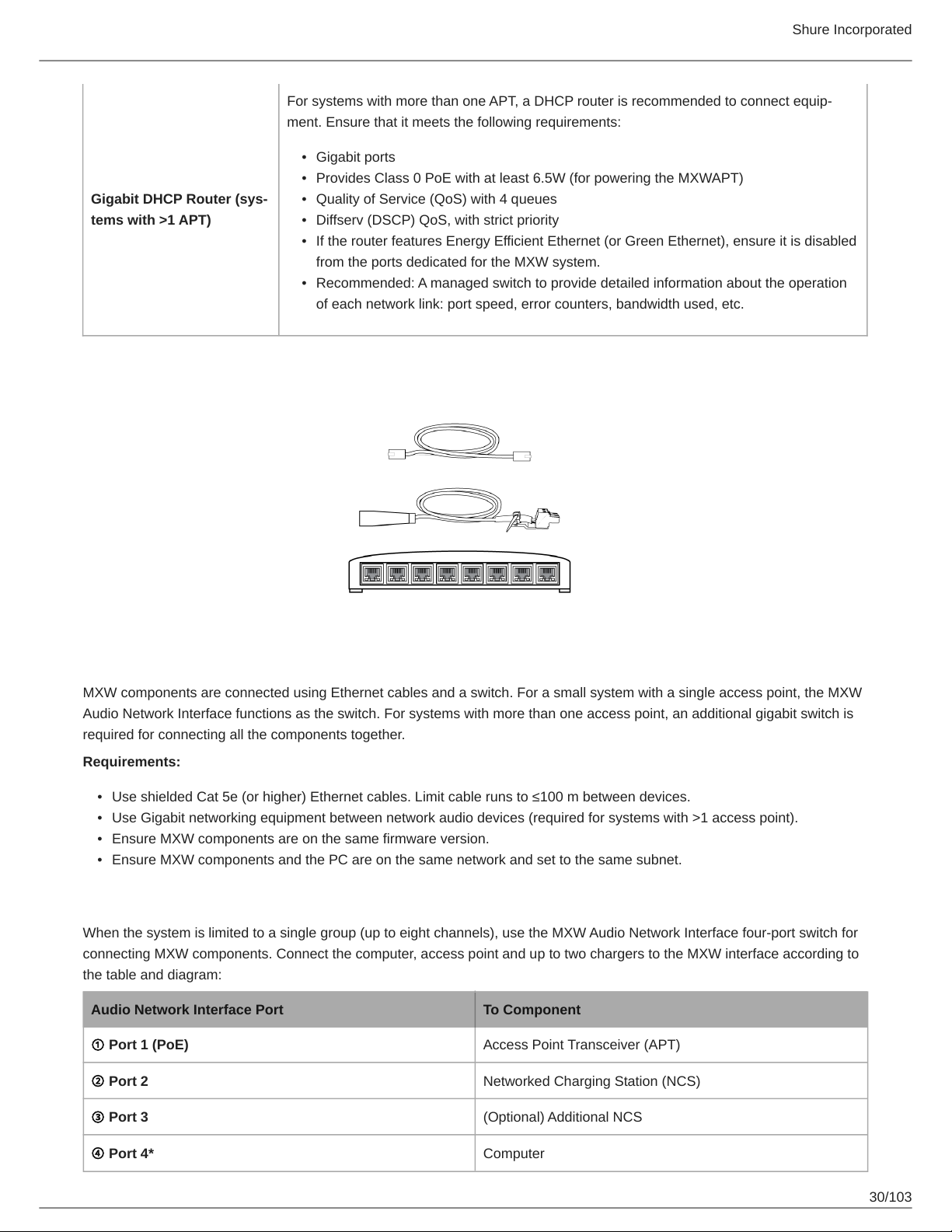
For systems with more than one APT, a DHCP router is recommended to connect equip
ment. Ensure that it meets the following requirements:
•
Gigabit ports
•
Provides Class 0 PoE with at least 6.5W (for powering the MXWAPT)
•
Quality of Service (QoS) with 4 queues
•
Diffserv (DSCP) QoS, with strict priority
•
If the router features Energy Efficient Ethernet (or Green Ethernet), ensure it is disabled
from the ports dedicated for the MXW system.
•
Recommended: A managed switch to provide detailed information about the operation
of each network link: port speed, error counters, bandwidth used, etc.
Connecting MXW Components
MXW components are connected using Ethernet cables and a switch. For a small system with a single access point, the MXW
Audio Network Interface functions as the switch. For systems with more than one access point, an additional gigabit switch is
required for connecting all the components together.
Requirements:
•
Use shielded Cat 5e (or higher) Ethernet cables. Limit cable runs to ≤100 m between devices.
•
Use Gigabit networking equipment between network audio devices (required for systems with >1 access point).
•
Ensure MXW components are on the same firmware version.
•
Ensure MXW components and the PC are on the same network and set to the same subnet.
Single Group System (1 Access Point)
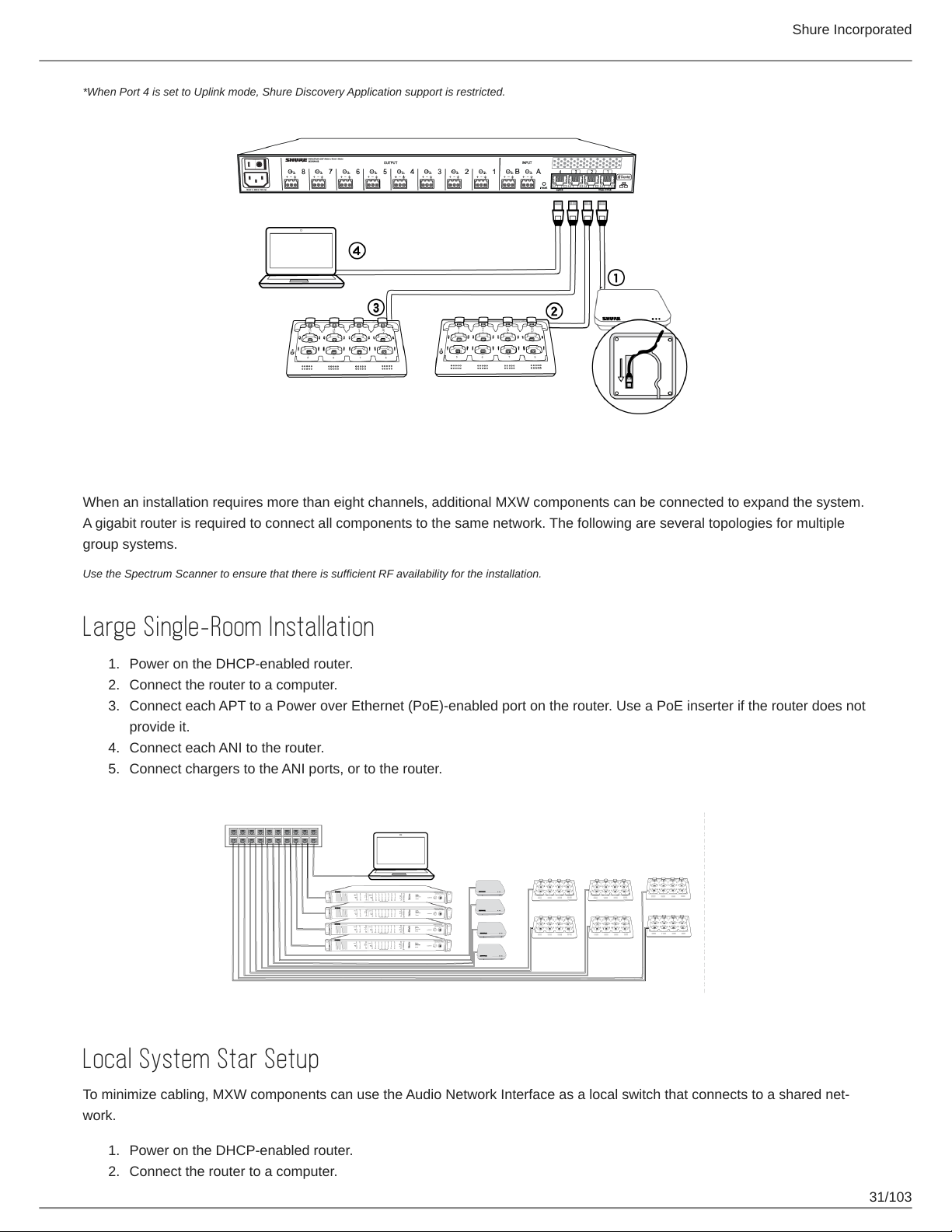
When the system is limited to a single group (up to eight channels), use the MXW Audio Network Interface four-port switch for
connecting MXW components. Connect the computer, access point and up to two chargers to the MXW interface according to
the table and diagram:
Audio Network Interface Port To Component
① Port 1 (PoE) Access Point Transceiver (APT)
② Port 2 Networked Charging Station (NCS)
③ Port 3 (Optional) Additional NCS
④ Port 4* Computer
30/103
Page 31
Shure Incorporated
*When Port 4 is set to Uplink mode, Shure Discovery Application support is restricted.
Multiple Group System (>1 Access Point)
When an installation requires more than eight channels, additional MXW components can be connected to expand the system.
A gigabit router is required to connect all components to the same network. The following are several topologies for multiple
group systems.
Use the Spectrum Scanner to ensure that there is sufficient RF availability for the installation.
Large Single-Room Installation
1.
Power on the DHCP-enabled router.
2.
Connect the router to a computer.
3.
Connect each APT to a Power over Ethernet (PoE)-enabled port on the router. Use a PoE inserter if the router does not
provide it.
4.
Connect each ANI to the router.
5.
Connect chargers to the ANI ports, or to the router.
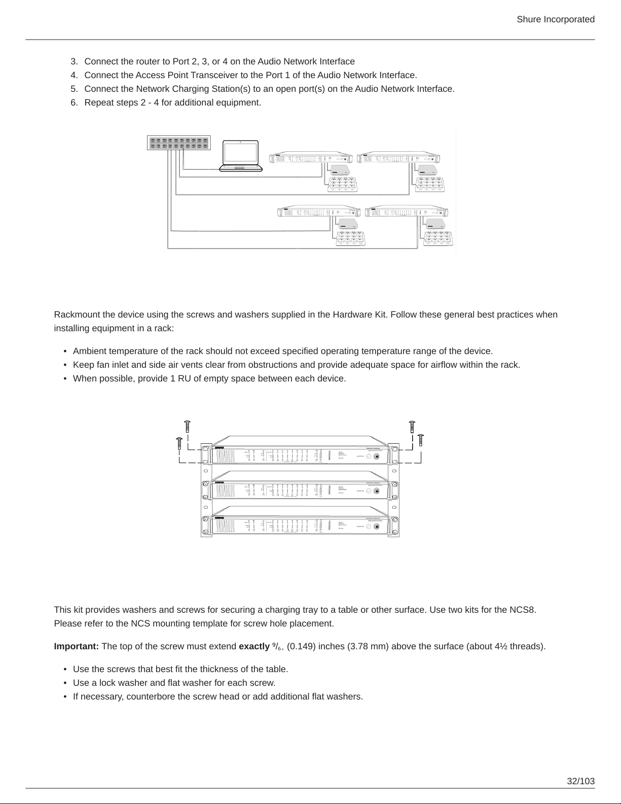
Local System Star Setup
To minimize cabling, MXW components can use the Audio Network Interface as a local switch that connects to a shared net
work.
1.
Power on the DHCP-enabled router.
2.
Connect the router to a computer.
31/103
Page 32
Shure Incorporated
3.
Connect the router to Port 2, 3, or 4 on the Audio Network Interface
4.
Connect the Access Point Transceiver to the Port 1 of the Audio Network Interface.
5.
Connect the Network Charging Station(s) to an open port(s) on the Audio Network Interface.
6.
Repeat steps 2 - 4 for additional equipment.
Rack Installation
Rackmount the device using the screws and washers supplied in the Hardware Kit. Follow these general best practices when
installing equipment in a rack:
•
Ambient temperature of the rack should not exceed specified operating temperature range of the device.
•
Keep fan inlet and side air vents clear from obstructions and provide adequate space for airflow within the rack.
•
When possible, provide 1 RU of empty space between each device.
Securing the Charging Station
This kit provides washers and screws for securing a charging tray to a table or other surface. Use two kits for the NCS8.
Please refer to the NCS mounting template for screw hole placement.
Important: The top of the screw must extend exactly ⁹/₆₄ (0.149) inches (3.78 mm) above the surface (about 4½ threads).
•
Use the screws that best fit the thickness of the table.
•
Use a lock washer and flat washer for each screw.
•
If necessary, counterbore the screw head or add additional flat washers.
32/103
Page 33
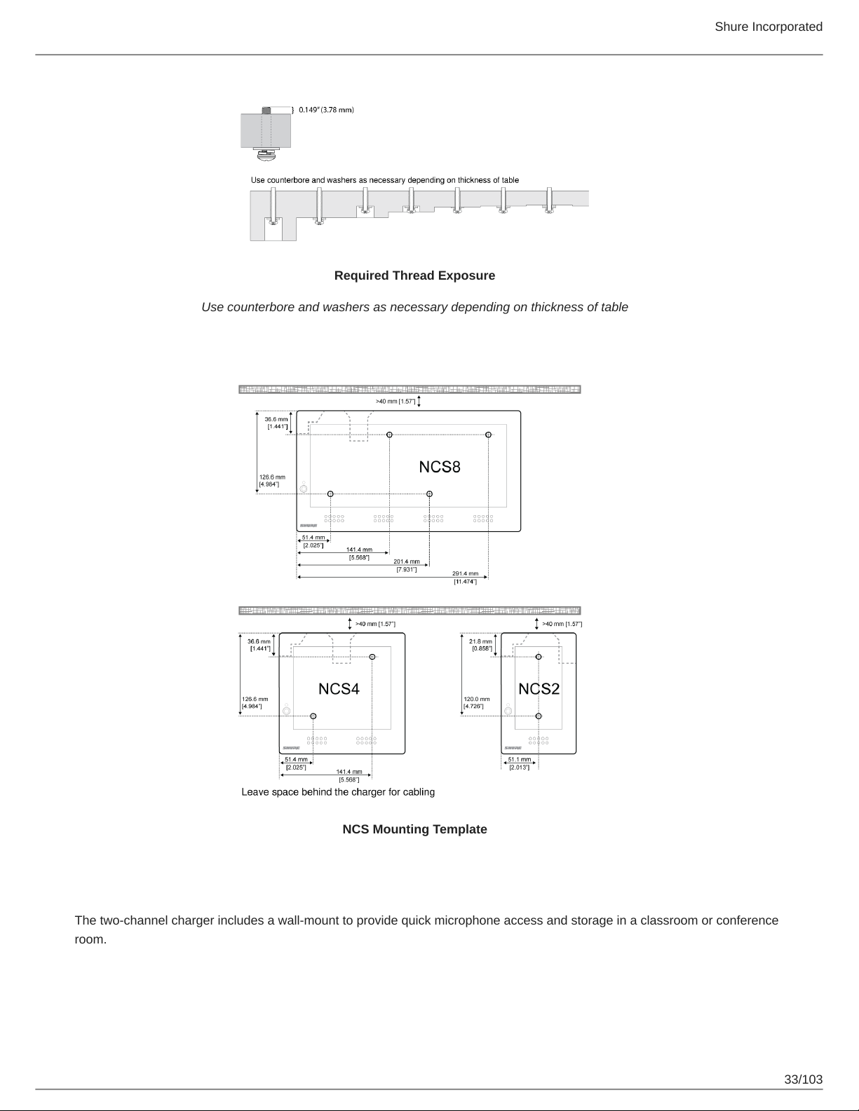
Required Thread Exposure
Use counterbore and washers as necessary depending on thickness of table
Shure Incorporated
NCS Mounting Template
Two-Channel Charger Wall Mount
The two-channel charger includes a wall-mount to provide quick microphone access and storage in a classroom or conference
room.
33/103
Page 34
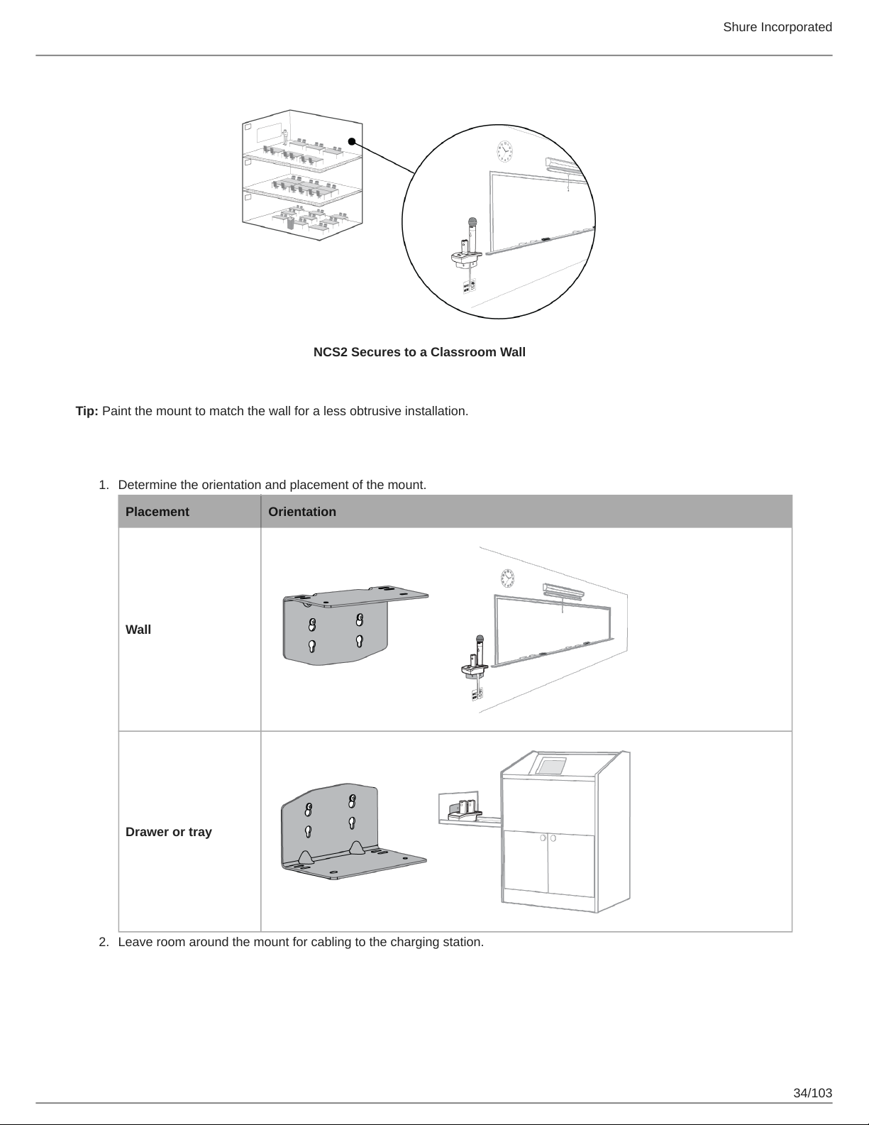
NCS2 Secures to a Classroom Wall
Tip: Paint the mount to match the wall for a less obtrusive installation.
Shure Incorporated
Installation
1.
Determine the orientation and placement of the mount.
Placement Orientation
Wall
Drawer or tray
2.
Leave room around the mount for cabling to the charging station.
34/103
Page 35
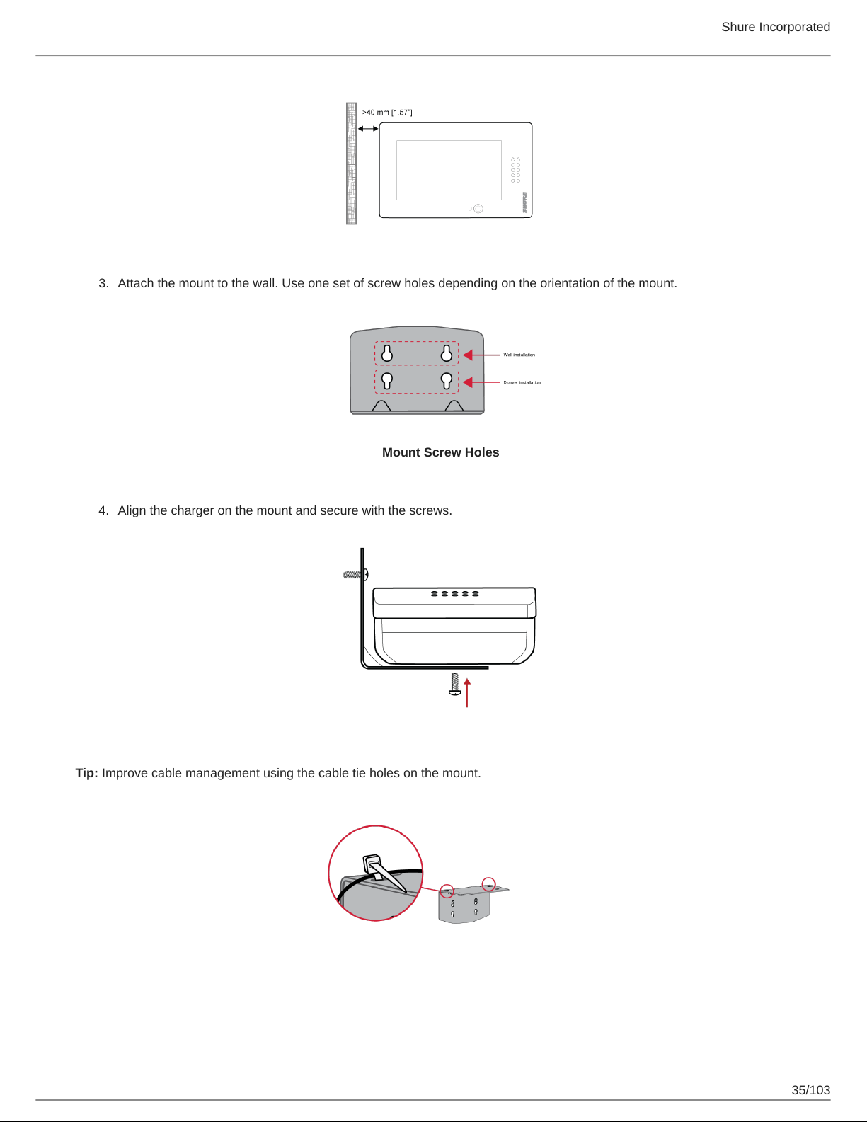
3.4.Attach the mount to the wall. Use one set of screw holes depending on the orientation of the mount.
Shure Incorporated
Mount Screw Holes
Align the charger on the mount and secure with the screws.
Tip: Improve cable management using the cable tie holes on the mount.
35/103
Page 36
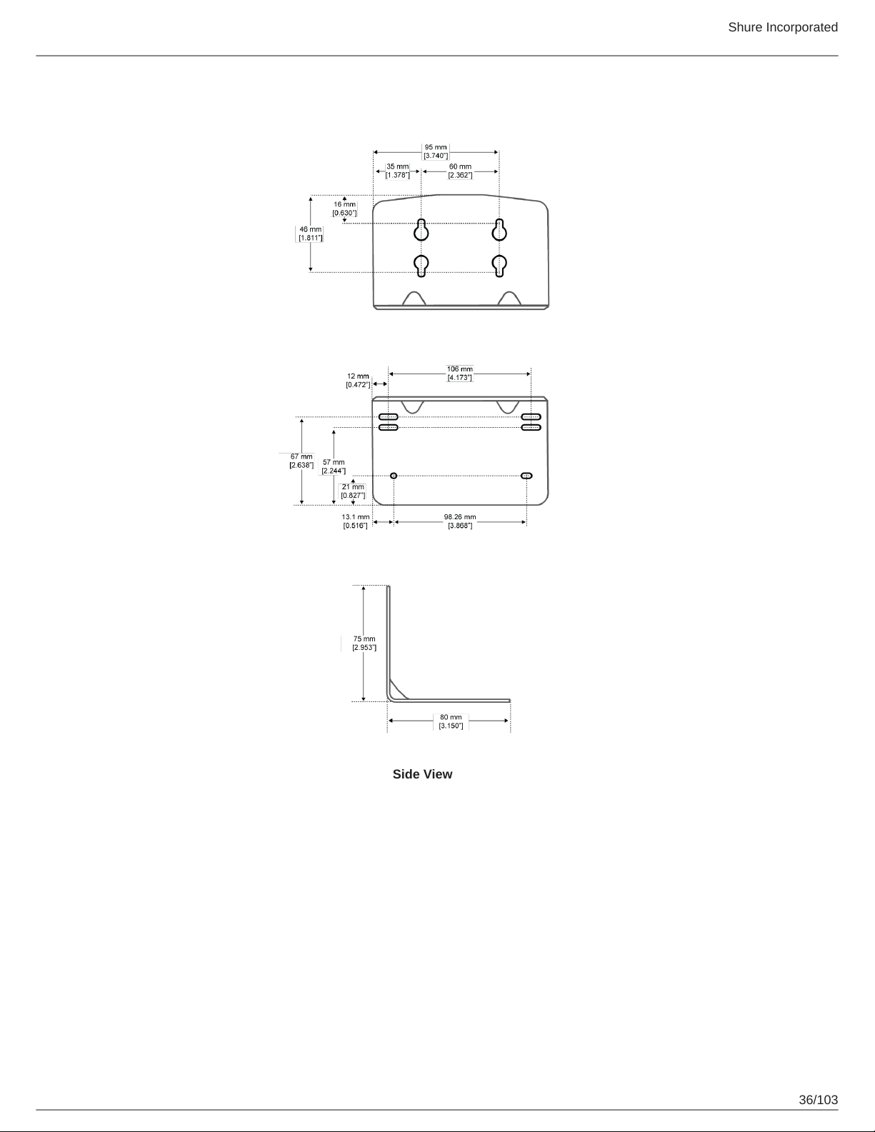
NCS2 Mount Dimensions
Shure Incorporated
Side View
36/103
Page 37
Shure Incorporated
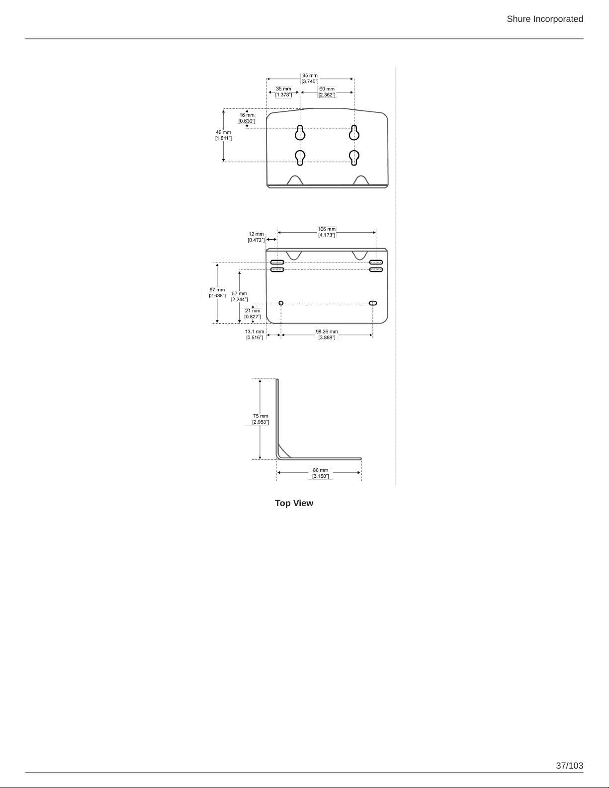
Top View
37/103
Page 38
Shure Incorporated
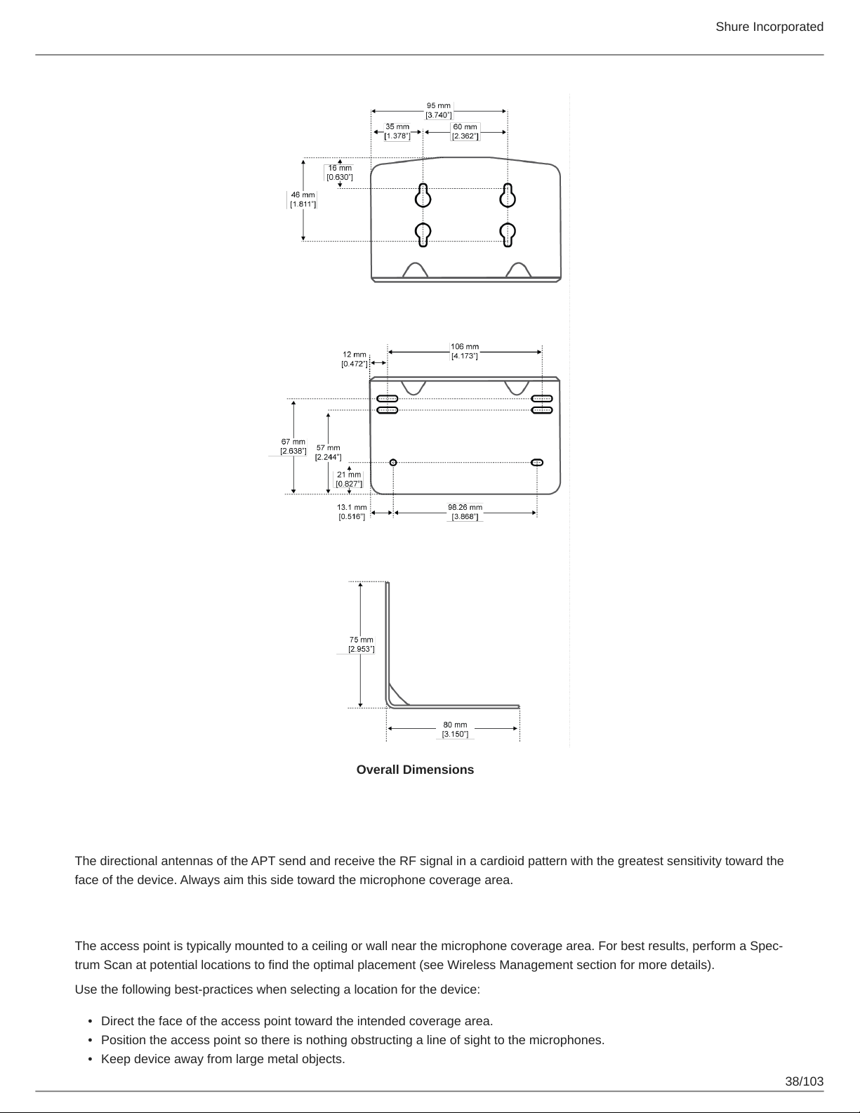
Overall Dimensions
Mount the Access Point Transceiver
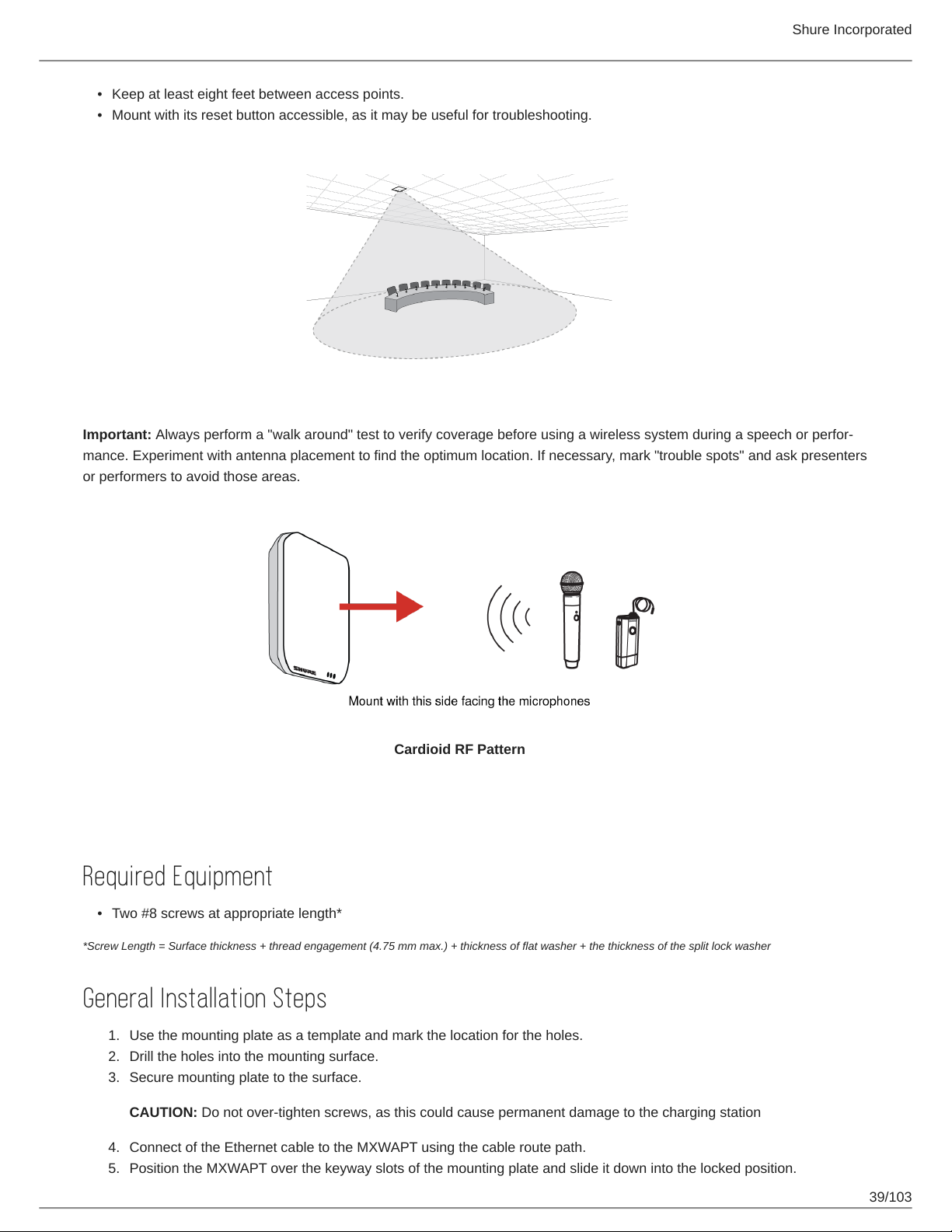
The directional antennas of the APT send and receive the RF signal in a cardioid pattern with the greatest sensitivity toward the
face of the device. Always aim this side toward the microphone coverage area.
Select a Location
The access point is typically mounted to a ceiling or wall near the microphone coverage area. For best results, perform a Spec
trum Scan at potential locations to find the optimal placement (see Wireless Management section for more details).
Use the following best-practices when selecting a location for the device:
•
Direct the face of the access point toward the intended coverage area.
•
Position the access point so there is nothing obstructing a line of sight to the microphones.
•
Keep device away from large metal objects.
38/103
Page 39
Shure Incorporated
•
Keep at least eight feet between access points.
•
Mount with its reset button accessible, as it may be useful for troubleshooting.
Important: Always perform a "walk around" test to verify coverage before using a wireless system during a speech or perfor
mance. Experiment with antenna placement to find the optimum location. If necessary, mark "trouble spots" and ask presenters
or performers to avoid those areas.
Cardioid RF Pattern
Securing to a Wall or Ceiling
Required Equipment
•
Two #8 screws at appropriate length*
*Screw Length = Surface thickness + thread engagement (4.75 mm max.) + thickness of flat washer + the thickness of the split lock washer
General Installation Steps
1.
Use the mounting plate as a template and mark the location for the holes.
2.
Drill the holes into the mounting surface.
3.
Secure mounting plate to the surface.
CAUTION: Do not over-tighten screws, as this could cause permanent damage to the charging station
4.
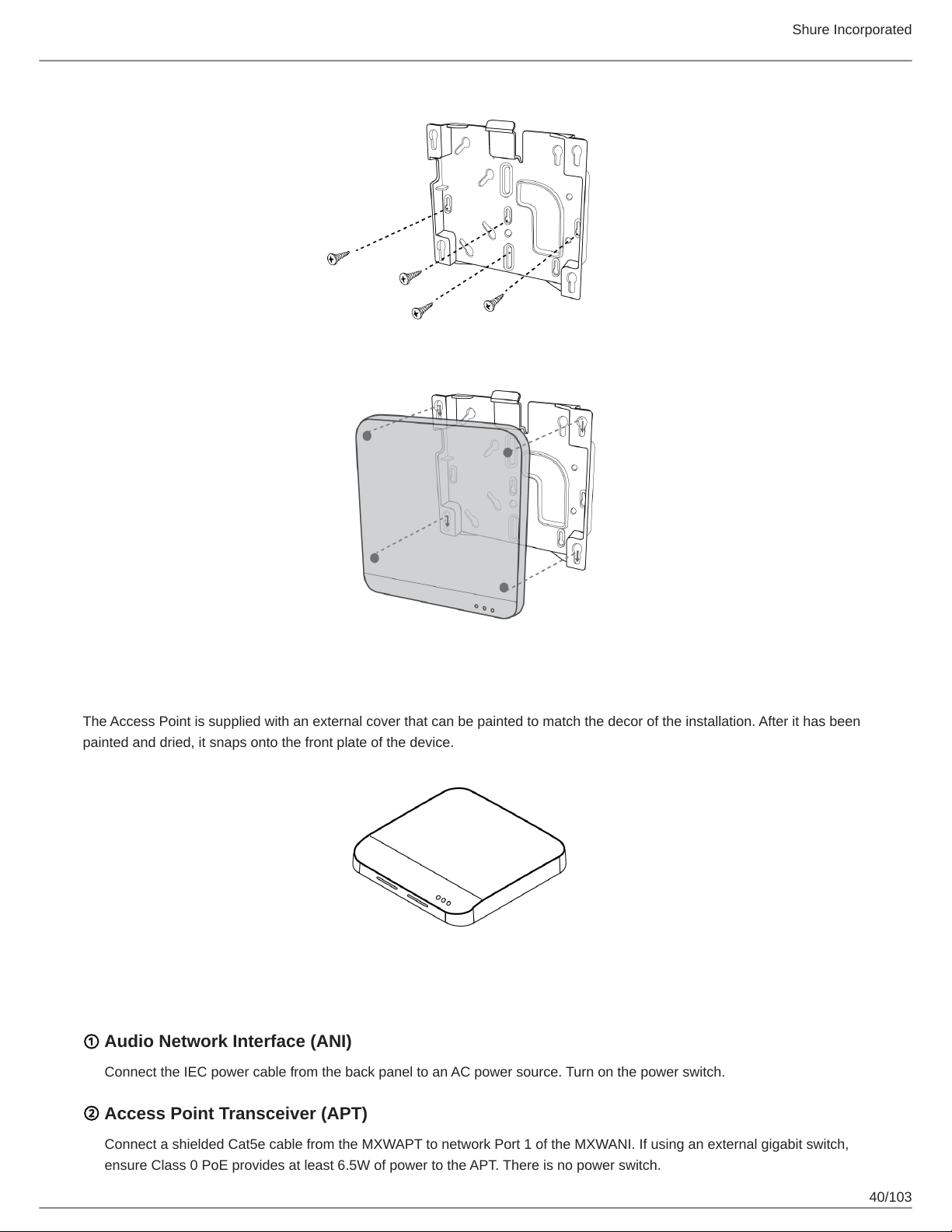
Connect of the Ethernet cable to the MXWAPT using the cable route path.
5.
Position the MXWAPT over the keyway slots of the mounting plate and slide it down into the locked position.
39/103
Page 40
Shure Incorporated
External Cover for Painting
The Access Point is supplied with an external cover that can be painted to match the decor of the installation. After it has been
painted and dried, it snaps onto the front plate of the device.
Power the Hardware
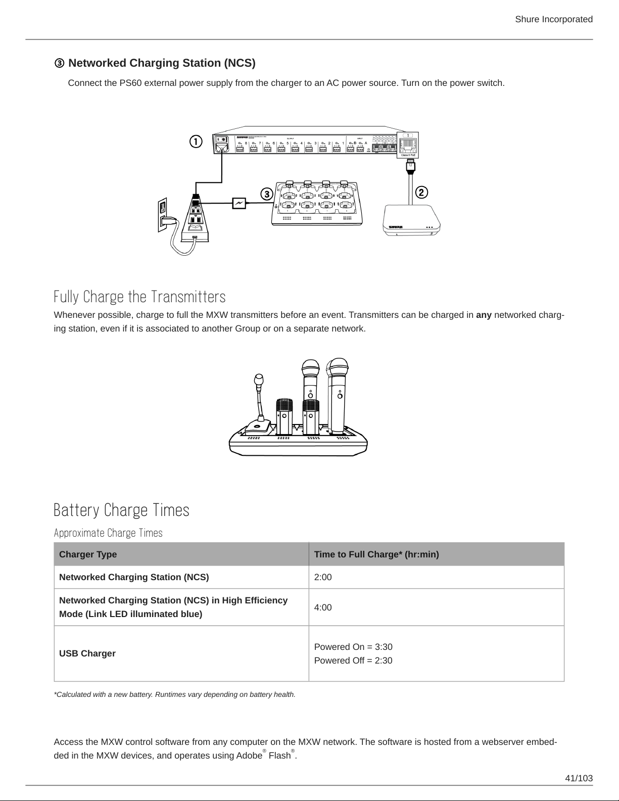
① Audio Network Interface (ANI)
Connect the IEC power cable from the back panel to an AC power source. Turn on the power switch.
② Access Point Transceiver (APT)
Connect a shielded Cat5e cable from the MXWAPT to network Port 1 of the MXWANI. If using an external gigabit switch,
ensure Class 0 PoE provides at least 6.5W of power to the APT. There is no power switch.
40/103
Page 41
Shure Incorporated
③ Networked Charging Station (NCS)
Connect the PS60 external power supply from the charger to an AC power source. Turn on the power switch.
Fully Charge the Transmitters
Whenever possible, charge to full the MXW transmitters before an event. Transmitters can be charged in any networked charg
ing station, even if it is associated to another Group or on a separate network.
Battery Charge Times
Approximate Charge Times
Charger Type Time to Full Charge* (hr:min)
Networked Charging Station (NCS) 2:00
Networked Charging Station (NCS) in High Efficiency
Mode (Link LED illuminated blue)
USB Charger
*Calculated with a new battery. Runtimes vary depending on battery health.
4:00
Powered On = 3:30
Powered Off = 2:30
Open the MXW Control Software
Access the MXW control software from any computer on the MXW network. The software is hosted from a webserver embed
ded in the MXW devices, and operates using Adobe Flash .
® ®
41/103
Page 42
There are two different control interfaces for MXW devices:
•
MXW system (hosted in APT): For comprehensive control of key setup, monitoring and management functions for the
MXW system. Accessed from the Access Point Transceiver (APT).
•
Audio Inputs and Outputs (hosted in ANI): For sending audio channels on and off the Dante network. Accessed from the
Audio Network Interface (ANI).
1.
Get the Shure Web Device Discovery application.
Get the Shure Web Device Discovery Application to see devices on the network and open the control interface. Down
load the software from www.shure.com/software (includes Bonjour device discovery tool).
2.
Connect the computer to the MXW network.
The computer accesses the control software from an embedded web server on the device. All networked devices must
be connected to the same network (set to the same subnet).
3.
Turn off WiFi (recommended)
For best results, turn off the PC's WiFi to force the wired network interface.
4.
Open the Shure Web Device Discovery application.
Shure Incorporated
Open the application to view Shure devices on the network that use an embedded server for control software, such as
the APT. You can use the Identify button to flash a device's LEDs for easy identification.
5.
Open the MXW Control Software
Double-click on any APT to open the MXW System control software. The application can be set to open by IP address
or DNS name (selectable from the Preferences drop-down).
6.
Enter Default Password
Enter the default password 'admin' to access the control software.
7.
Bookmark the Webpage (recommended)
Bookmark the IP address of the device when it is set to a Static IP address. Bookmark the device's DNS name when
the IP mode is set to Automatic (DHCP).
Operating System Requirements
To operate the control software, the computer must meet the following requirements:
•
Windows: Windows XP, Windows Vista and Windows 7
•
Apple: Mac OSX 10.6 and higher (Intel Core 2 Duo processor and later)
•
Latest version of AdobeFlash Player
System Set Up
Group Devices to Form Audio Channels
Use the group configuration to form the audio channel between the microphone, the access point (APT), charger and audio
output device. The audio channel establishes the audio routing, RF coordination, and data control for a set of devices. Groups
are comprised of networked devices (set to the same subnet). A component can belong to one group at a time.
42/103
Page 43
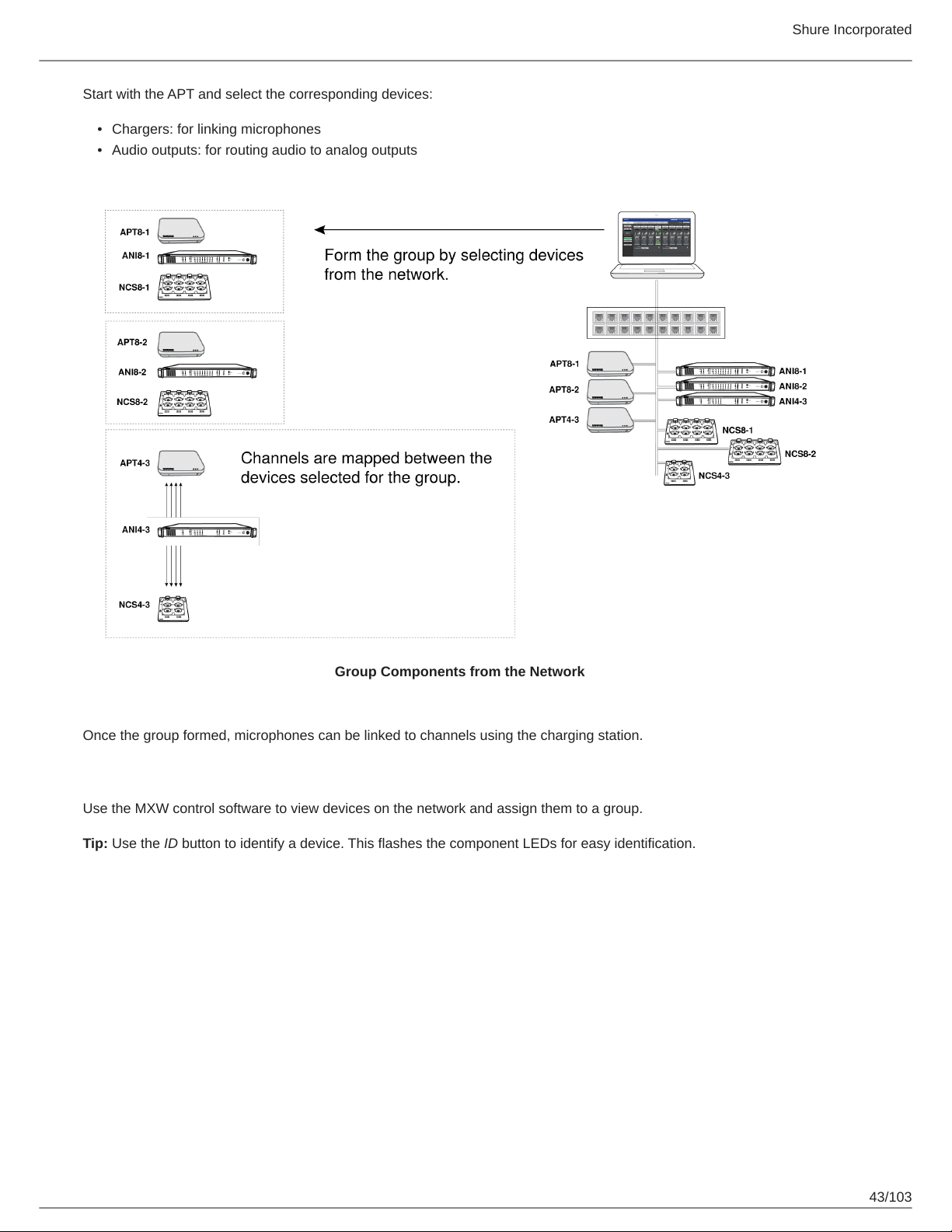
Start with the APT and select the corresponding devices:
•
Chargers: for linking microphones
•
Audio outputs: for routing audio to analog outputs
Shure Incorporated
Group Components from the Network
Once the group formed, microphones can be linked to channels using the charging station.
Select Devices for the Group
Use the MXW control software to view devices on the network and assign them to a group.
Tip: Use the ID button to identify a device. This flashes the component LEDs for easy identification.
43/103
Page 44
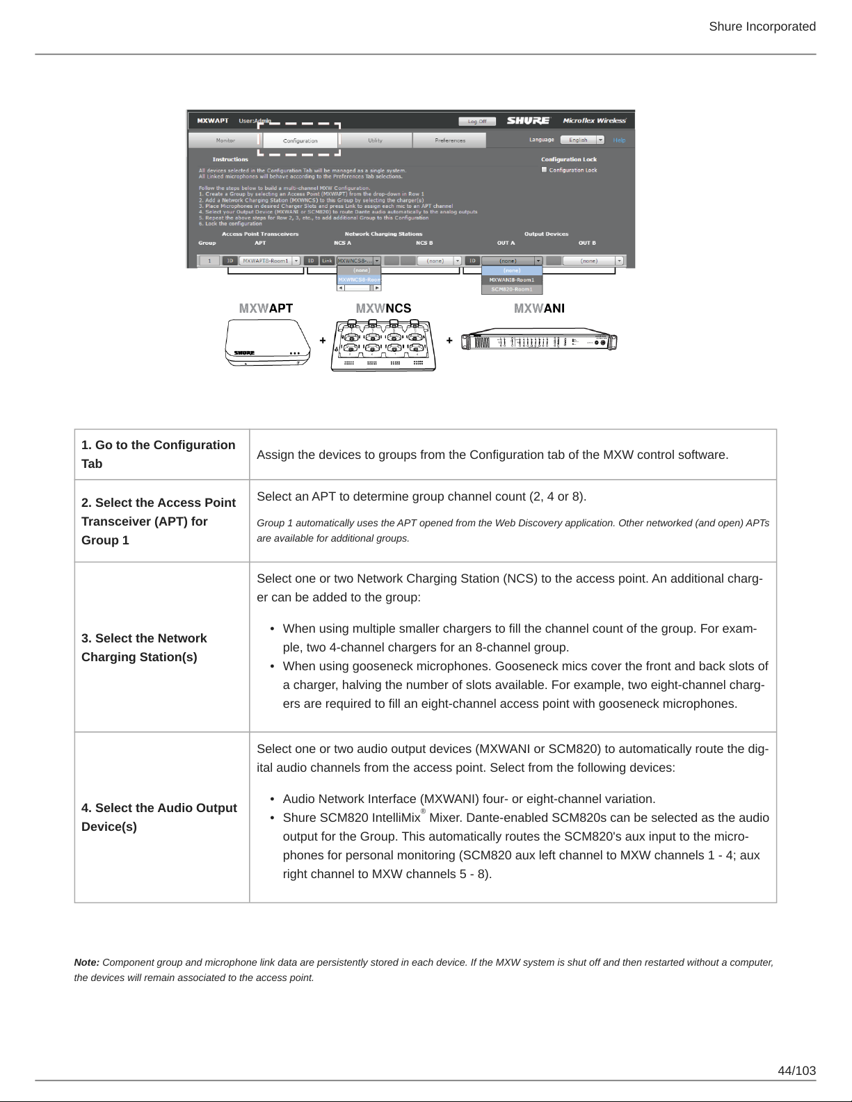
Shure Incorporated
1. Go to the Configuration
Tab
2. Select the Access Point
Transceiver (APT) for
Group 1
3. Select the Network
Charging Station(s)
4. Select the Audio Output
Device(s)
Assign the devices to groups from the Configuration tab of the MXW control software.
Select an APT to determine group channel count (2, 4 or 8).
Group 1 automatically uses the APT opened from the Web Discovery application. Other networked (and open) APTs
are available for additional groups.
Select one or two Network Charging Station (NCS) to the access point. An additional charg
er can be added to the group:
•
When using multiple smaller chargers to fill the channel count of the group. For exam
ple, two 4-channel chargers for an 8-channel group.
•
When using gooseneck microphones. Gooseneck mics cover the front and back slots of
a charger, halving the number of slots available. For example, two eightchannel charg
ers are required to fill an eight-channel access point with gooseneck microphones.
Select one or two audio output devices (MXWANI or SCM820) to automatically route the dig
ital audio channels from the access point. Select from the following devices:
•
Audio Network Interface (MXWANI) four- or eight-channel variation.
•
Shure SCM820 IntelliMix Mixer. Dante-enabled SCM820s can be selected as the audio
®
output for the Group. This automatically routes the SCM820's aux input to the micro
phones for personal monitoring (SCM820 aux left channel to MXW channels 1 - 4; aux
right channel to MXW channels 5 - 8).
Note: Component group and microphone link data are persistently stored in each device. If the MXW system is shut off and then restarted without a computer,
the devices will remain associated to the access point.
44/103
Page 45
Shure Incorporated
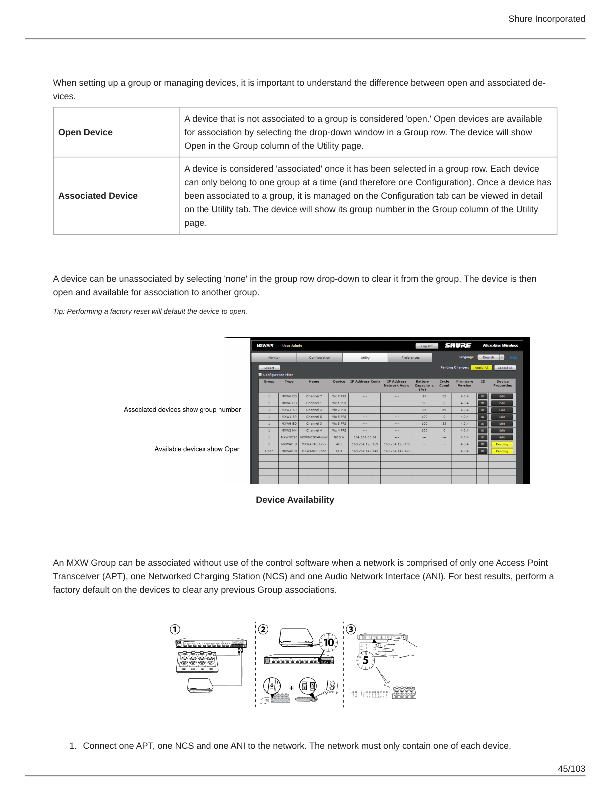
Device Availability
When setting up a group or managing devices, it is important to understand the difference between open and associated de
vices.
A device that is not associated to a group is considered 'open.' Open devices are available
Open Device
Associated Device
A device can be unassociated by selecting 'none' in the group row drop-down to clear it from the group. The device is then
open and available for association to another group.
for association by selecting the drop-down window in a Group row. The device will show
Open in the Group column of the Utility page.
A device is considered 'associated' once it has been selected in a group row. Each device
can only belong to one group at a time (and therefore one Configuration). Once a device has
been associated to a group, it is managed on the Configuration tab can be viewed in detail
on the Utility tab. The device will show its group number in the Group column of the Utility
page.
Tip: Performing a factory reset will default the device to open.
Device Availability
Automatic Group Setup
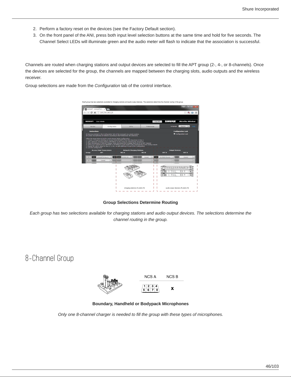
An MXW Group can be associated without use of the control software when a network is comprised of only one Access Point
Transceiver (APT), one Networked Charging Station (NCS) and one Audio Network Interface (ANI). For best results, perform a
factory default on the devices to clear any previous Group associations.
1.
Connect one APT, one NCS and one ANI to the network. The network must only contain one of each device.
45/103
Page 46
Shure Incorporated
2.3.Perform a factory reset on the devices (see the Factory Default section).
On the front panel of the ANI, press both input level selection buttons at the same time and hold for five seconds. The
Channel Select LEDs will illuminate green and the audio meter will flash to indicate that the association is successful.
Channel Routing between Devices
Channels are routed when charging stations and output devices are selected to fill the APT group (2-, 4-, or 8-channels). Once
the devices are selected for the group, the channels are mapped between the charging slots, audio outputs and the wireless
receiver.
Group selections are made from the Configuration tab of the control interface.
Group Selections Determine Routing
Each group has two selections available for charging stations and audio output devices. The selections determine the
channel routing in the group.
Charging Station Examples
8-Channel Group
Boundary, Handheld or Bodypack Microphones
Only one 8-channel charger is needed to fill the group with these types of microphones.
46/103
Page 47
Shure Incorporated
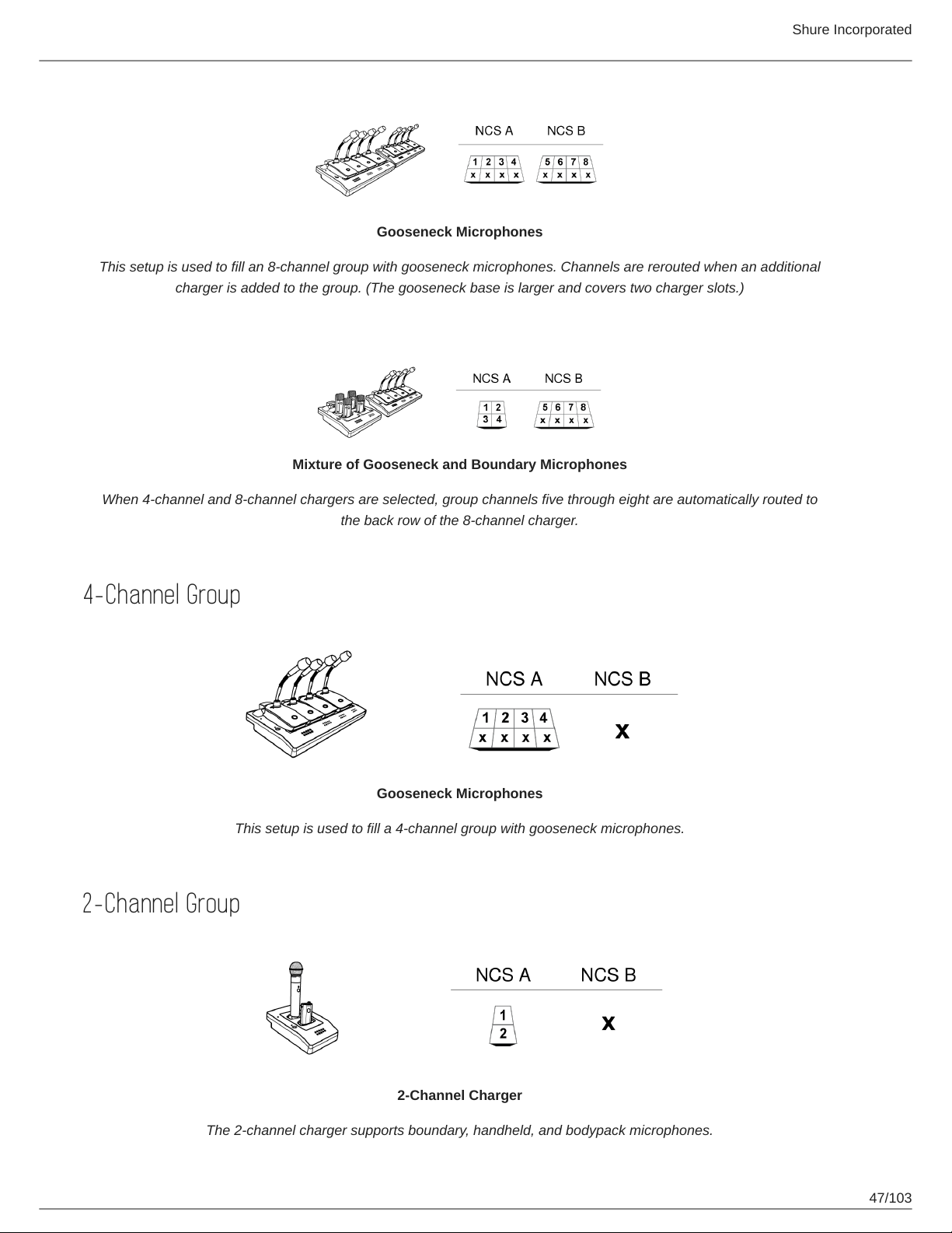
Gooseneck Microphones
This setup is used to fill an 8-channel group with gooseneck microphones. Channels are rerouted when an additional
charger is added to the group. (The gooseneck base is larger and covers two charger slots.)
Mixture of Gooseneck and Boundary Microphones
When 4-channel and 8-channel chargers are selected, group channels five through eight are automatically routed to
the back row of the 8-channel charger.
4-Channel Group
Gooseneck Microphones
This setup is used to fill a 4-channel group with gooseneck microphones.
2-Channel Group
2-Channel Charger
The 2-channel charger supports boundary, handheld, and bodypack microphones.
47/103
Page 48
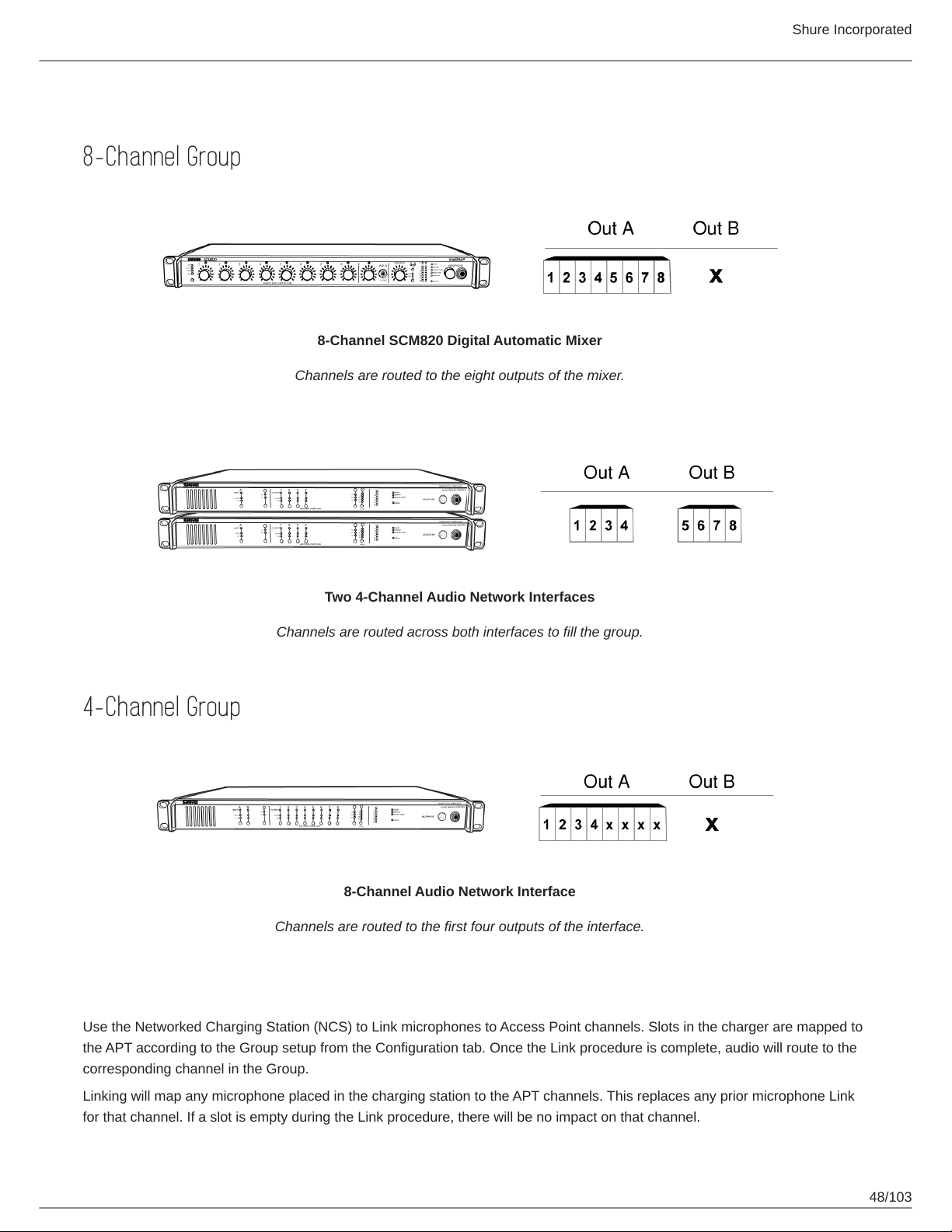
Audio Output Examples
8-Channel Group
Shure Incorporated
8-Channel SCM820 Digital Automatic Mixer
Channels are routed to the eight outputs of the mixer.
Two 4-Channel Audio Network Interfaces
Channels are routed across both interfaces to fill the group.
4-Channel Group
8-Channel Audio Network Interface
Channels are routed to the first four outputs of the interface.
Link Microphones to Group Channels
Use the Networked Charging Station (NCS) to Link microphones to Access Point channels. Slots in the charger are mapped to
the APT according to the Group setup from the Configuration tab. Once the Link procedure is complete, audio will route to the
corresponding channel in the Group.
Linking will map any microphone placed in the charging station to the APT channels. This replaces any prior microphone Link
for that channel. If a slot is empty during the Link procedure, there will be no impact on that channel.
48/103
Page 49
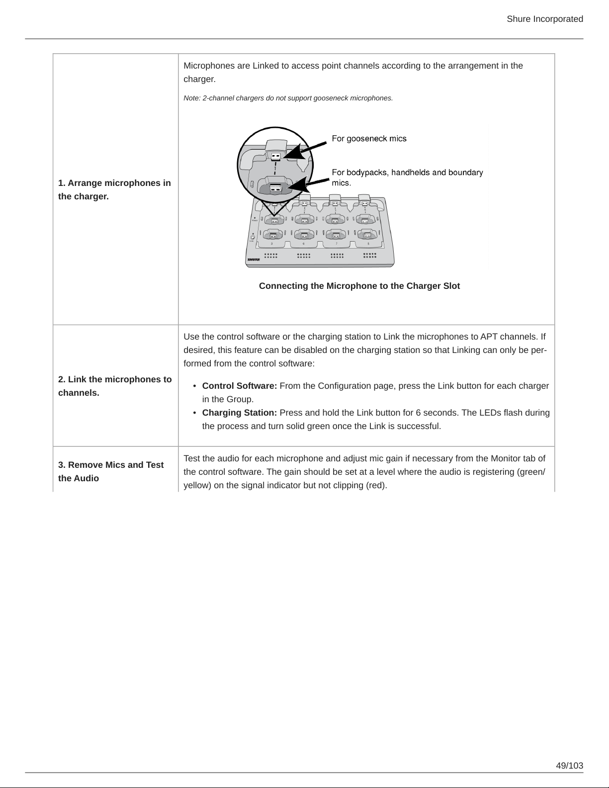
1. Arrange microphones in
the charger.
Shure Incorporated
Microphones are Linked to access point channels according to the arrangement in the
charger.
Note: 2-channel chargers do not support gooseneck microphones.
Connecting the Microphone to the Charger Slot
2. Link the microphones to
channels.
3. Remove Mics and Test
the Audio
Use the control software or the charging station to Link the microphones to APT channels. If
desired, this feature can be disabled on the charging station so that Linking can only be per
formed from the control software:
•
Control Software: From the Configuration page, press the Link button for each charger
in the Group.
•
Charging Station: Press and hold the Link button for 6 seconds. The LEDs flash during
the process and turn solid green once the Link is successful.
Test the audio for each microphone and adjust mic gain if necessary from the Monitor tab of
the control software. The gain should be set at a level where the audio is registering (green/
yellow) on the signal indicator but not clipping (red).
49/103
Page 50
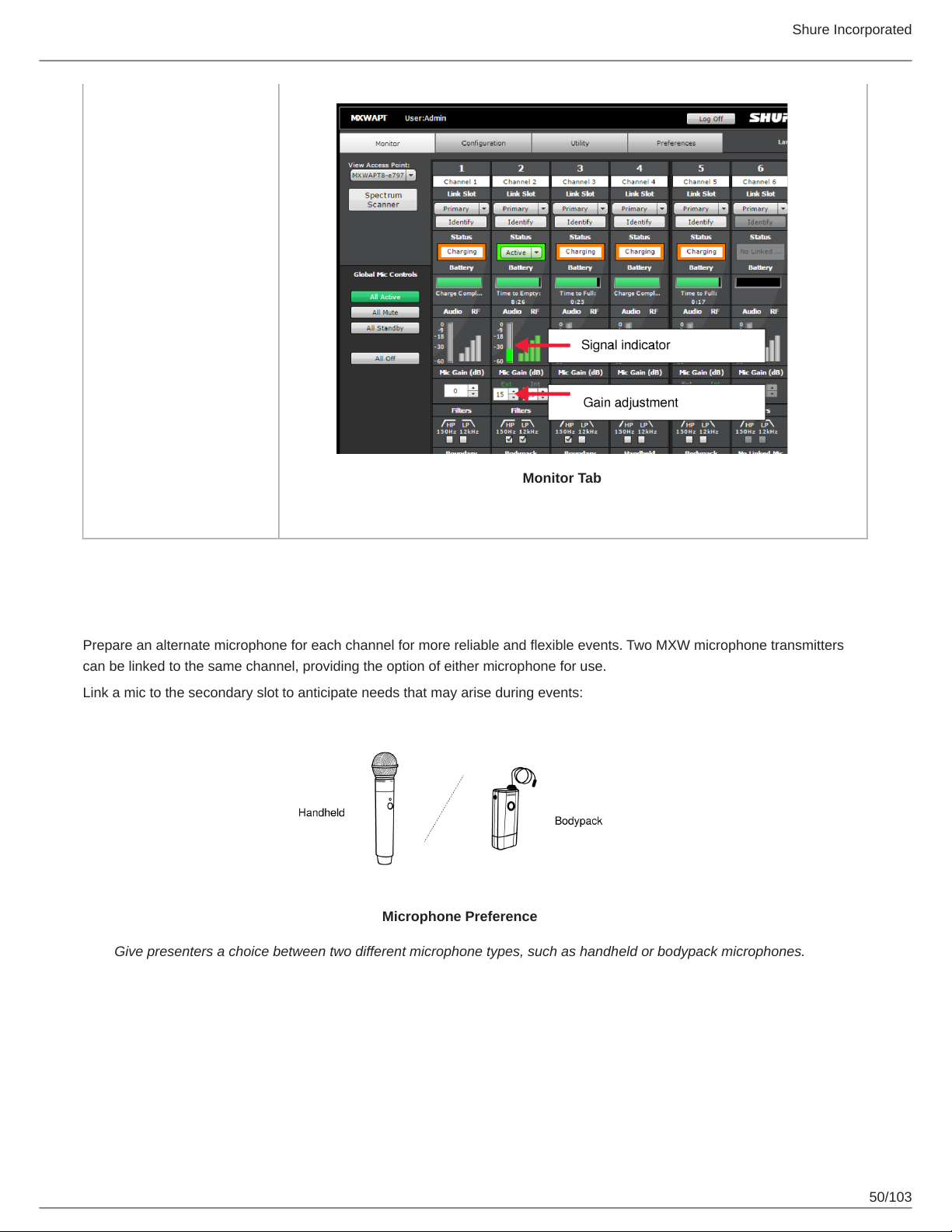
Monitor Tab
Shure Incorporated
Preparing a Backup Microphone
Prepare an alternate microphone for each channel for more reliable and flexible events. Two MXW microphone transmitters
can be linked to the same channel, providing the option of either microphone for use.
Link a mic to the secondary slot to anticipate needs that may arise during events:
Microphone Preference
Give presenters a choice between two different microphone types, such as handheld or bodypack microphones.
50/103
Page 51
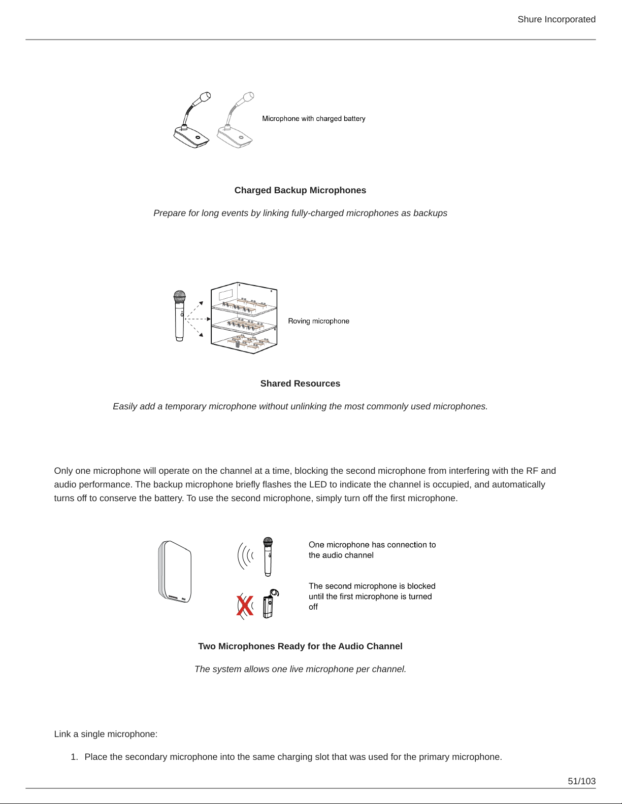
Charged Backup Microphones
Prepare for long events by linking fully-charged microphones as backups
Shure Incorporated
Shared Resources
Easily add a temporary microphone without unlinking the most commonly used microphones.
One Active Mic per Channel
Only one microphone will operate on the channel at a time, blocking the second microphone from interfering with the RF and
audio performance. The backup microphone briefly flashes the LED to indicate the channel is occupied, and automatically
turns off to conserve the battery. To use the second microphone, simply turn off the first microphone.
Two Microphones Ready for the Audio Channel
The system allows one live microphone per channel.
Procedure
Link a single microphone:
1.
Place the secondary microphone into the same charging slot that was used for the primary microphone.
51/103
Page 52
Shure Incorporated
2.
Open the MXW control software and go to the Monitor tab.
3.
Select Secondary in that channel's link slot.
4.
Select the Link button on the channel strip to link that microphone. The charger LEDs will flash when the procedure is
complete.
Link multiple microphones:
1.
Place the secondary microphones into the same charging slots that were used for the primary microphones.
2.
Open the MXW control software and go to the Configuration tab.
3.
Find the desired charger in the group row. Use the ID button to make sure the right charger is selected.
4.
Select the Link button in the group row.
5.
In the popup window, select All Secondary for the link slot.
Exchanging or Removing a Component
Exchanging a Transmitter
The same Link procedure is done to exchange a transmitter in a group. Place the new transmitter in the charger slot that corre
sponds to the desired channel and perform the Link procedure. This will map the new transmitter to that channel, and remove
any Link from the old transmitter.
If an NCS channel slot is empty during the Link procedure, the channel will remain unaffected.
Important: Use caution when replacing microphones, as the Link procedure applies for all microphones in the charger. The Link will immediately override any
existing microphone's audio and RF connection to the system.
Remove a Device from a Group
To remove a device from a group, open the MXW Control Software and go to the Configuration tab. In the group row, select the
device drop-down window that contains the desired device. Select 'none' to clear the device association.
Note: A factory reset will also remove the any association or Link status.
Link a Microphone Over the Network
To improve device management from a central help desk or technician station, a microphone can be linked to any group on the
network using a remote charging station. Using a control system, send the command strings* to replace a microphone for a
specific channel. Group settings are not affected by this procedure.
1.
Connect a spare charger to the network.
2.
Place the microphone in a charging slot.
3.
Modify the following command string according to the setup :
① PRI (primary) or SEC (secondary) channel link
② Charging slot number used for new microphone
③ Channel targeted for this procedure
④ IP address of the APT (device that stores the group settings)
4.
Send the command to the charger.
5.
Verify the command response:
52/103
Page 53
Shure Incorporated
*A comprehensive list of MXW command strings are available on the Shure website: www.shure.com, search "command
strings".
Large Installations
Shure SystemOn Software For Managing Large Systems
Shure SystemOn Audio Asset Management Software provides a central platform for managing mission critical, largescale de
ployments of Shure audio hardware across corporate and higher education networks. SystemOn goes beyond the functionality
of the MXW control software, working across subnets and APT groups to provide IT administrators and AV technicians the abili
ty to proactively monitor and control Shure hardware devices remotely using a laptop, smartphone or tablet.
Visit http://www.shure.com/SystemOn for more information.
High Density Mode
High Density (HD) mode creates additional channels for large meetings and crowded RF environments. HD mode doubles the
number of channels available in standard mode, with minor changes to some system features. You can set the density mode
for each APT individually to get the right blend of channel count and audio performance.
Density Mode Comparison
Feature Standard Density High Density
Channels available* Up to 40 Up to 80
Audio latency 18 ms 28 ms
Microphone battery life Up to 7 hours Up to 8 hours
EQ filters Optional Always on
Backchannel audio (headphone out
put on the microphone)
*For Americas region. See Maximum Channel Count table for availability worldwide.
Setting the Density Mode
Set the mode for each APT from the device properties:
1.
Go to MXW control software > Utility tab > [Find the desired APT] > Edit
2.
Choose a density mode:
◦
Standard (default)
◦
High
3.
Select Add updates to exit the device properties.
4.
Select Apply All from the Utility page to push to your devices.
Available Unavailable
Configurations: Managing Multiple Groups
Configurations allow multiple Groups to share the same preferences, global controls and log-ons. When an additional Group is
added to the Configuration tab, the new components will take on the preferences and global actions of that Configuration. For
example, all microphones Linked to Groups in that Configuration will mute when the global Mute All button is pressed.
53/103
Page 54
Shure Incorporated
For specialized applications, such as multiple room installation, separate Configurations can be created to independently con
trol component Groups.
Configuration Master
When using a Configuration to manage multiple groups, the system dynamically assigns a particular Access Point as the “Con
figuration Master". All Access Points in that Configuration use the Configuration Master Access Point as an entry point to the
same control interface. This enables the coordination of preferences and the synchronization of system operations across mul
tiple devices.
When the Configuration Master Access Point is unplugged (or PoE is powered off), a new master is quickly re-established to
maintain control of the Configuration. If the Configuration Master is manually removed by deselecting the Access Point from the
Group on the Configuration tab, there will be a pop-up warning "Are You Sure?". If Yes is selected, the browser will close and a
new Configuration Master is automatically selected. Use the Shure Discovery Application to re-open the control interface from
any remaining MXW Access Point.
Creating Separate Configurations
For installations that spread across multiple rooms, a different set of preferences and global controls may be required for a giv
en space. Do this by setting up a separate Configuration:
1.
Open the Shure Web Device Discovery Application.
2.
Select the Access Point that will be used for the new Configuration and open its control software. The APT must be
open (not already assigned to a group) in order to start a new configuration.
3.
Go to the Configuration tab.
4.
Select that Access Point from the drop down list in Row 1. Use the ID button to ensure the correct Access Point is se
lected.
5.
Select the charging station(s) and output device(s) to complete the Group.
6.
Repeat 4-5 for up to 10 Groups in the Configuration.
7.
Enable the Lock Configuration to improve network performance.
8.
Customize the Configuration as desired from the Preferences tab.
Note: Ensure that all APTs are connected to the same network and set to the same subnet, even if they are assigned to a separate Configuration. This en
sures the best system performance, highest channel count, and tightest digital audio clocking for the installation.
Locking the Configuration
Use the Lock Configuration feature to improve network performance and system stability. It is best practice to lock a configura
tion after setup to greatly reduce network traffic from MXW equipment. When systems exceed 15 APTs on the same network,
configuration locking is required for stable performance.
When locked, groups in that configuration are not editable.
54/103
Page 55
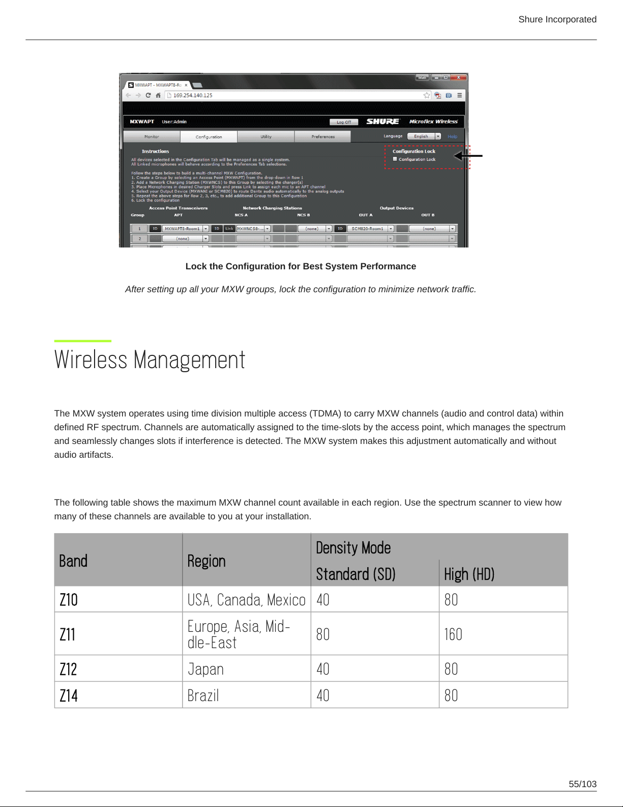
Lock the Configuration for Best System Performance
After setting up all your MXW groups, lock the configuration to minimize network traffic.
Shure Incorporated
Wireless Management
Overview of Channel Coordination
The MXW system operates using time division multiple access (TDMA) to carry MXW channels (audio and control data) within
defined RF spectrum. Channels are automatically assigned to the time-slots by the access point, which manages the spectrum
and seamlessly changes slots if interference is detected. The MXW system makes this adjustment automatically and without
audio artifacts.
Maximum Channel Count
The following table shows the maximum MXW channel count available in each region. Use the spectrum scanner to view how
many of these channels are available to you at your installation.
Density Mode
Band Region
Standard (SD) High (HD)
Z10 USA, Canada, Mexico 40 80
Z11
Europe, Asia, Mid-
80 160
dle-East
Z12 Japan 40 80
Z14 Brazil 40 80
55/103
Page 56
Shure Incorporated
Density Mode
Band Region
Standard (SD) High (HD)
Z15 Taiwan 64 128
Scanning Available RF Spectrum
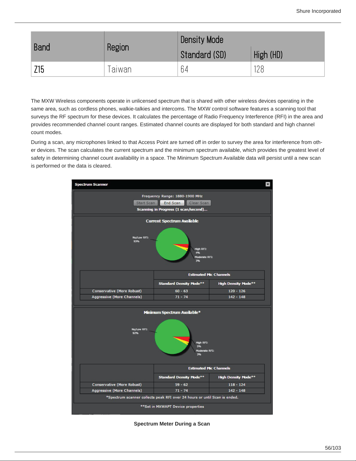
The MXW Wireless components operate in unlicensed spectrum that is shared with other wireless devices operating in the
same area, such as cordless phones, walkie-talkies and intercoms. The MXW control software features a scanning tool that
surveys the RF spectrum for these devices. It calculates the percentage of Radio Frequency Interference (RFI) in the area and
provides recommended channel count ranges. Estimated channel counts are displayed for both standard and high channel
count modes.
During a scan, any microphones linked to that Access Point are turned off in order to survey the area for interference from oth
er devices. The scan calculates the current spectrum and the minimum spectrum available, which provides the greatest level of
safety in determining channel count availability in a space. The Minimum Spectrum Available data will persist until a new scan
is performed or the data is cleared.
Spectrum Meter During a Scan
56/103
Page 57
Displays the percentage of available spectrum
Radio Frequency Interference (RFI)
The scanner analyzes the spectrum and divides the data into three categories:
No/Low (Green)
Clean RF available for MXW system.
Moderate (Yellow)
Some moderate interference is detected, still usable by the MXW system.
High (Red)
Busy RF occupied by other devices.
Estimated Mic Channel Count
The scanner provides two estimate levels for MXW microphones:
Shure Incorporated
Conservative (More Robust)
Reference this channel estimate for maximum channel stability. It includes extra usable spectrum for optimal interference
avoidance, allowing multiple microphones to find available frequencies simultaneously.
Aggressive (More Channels).
Reference this estimate to get the most channels on air. It reserves only the minimum required extra spectrum for interfer
ence avoidance. Be sure to occasionally monitor the spectrum and make channel adjustments if the RFI increases.
Performing a Scan
Follow these steps to perform RF scan.
Tip: Perform the scan during typical hours of operation to best capture the typical interference in an environment.
1.
Ensure all typically used devices are turned on, including any MXW equipment already in use.
2.
Place the new MXW Access Point near the location it will be mounted.
3.
Ensure the APT is on the same network and set to the same subnet as the other MXW equipment.
4.
Open MXW control software to the Monitor tab. Make sure the new Access Point is selected from the drop down on the
top left corner of the Monitor tab.
5.
Select the Spectrum Scanner to open the window.
6.
Select the Start Scan button at the top of the window. If any microphones are Linked to that Access Point, they will be
turned off during the scan.
7.
For best results, allow the scan to run for up to 24 hours to get a full snapshot of the spectrum throughout the day.
Press End Scan to end the scan mode.
PHS Detection
The APT scanner may discover interference from devices that have priority in the JDECT spectrum. When personal handy-
phone systems (PHS) are detected, the MXW system will automatically reduce operation to 40% of typical spectrum use.
The APT automatically scans for PHS upon power up and when the Spectrum Scanner is manually launched from the Monitor
tab. The Spectrum Scanner includes the PHS limits when calculating the maximum channel estimates to provide the safest es
timates.
57/103
Page 58
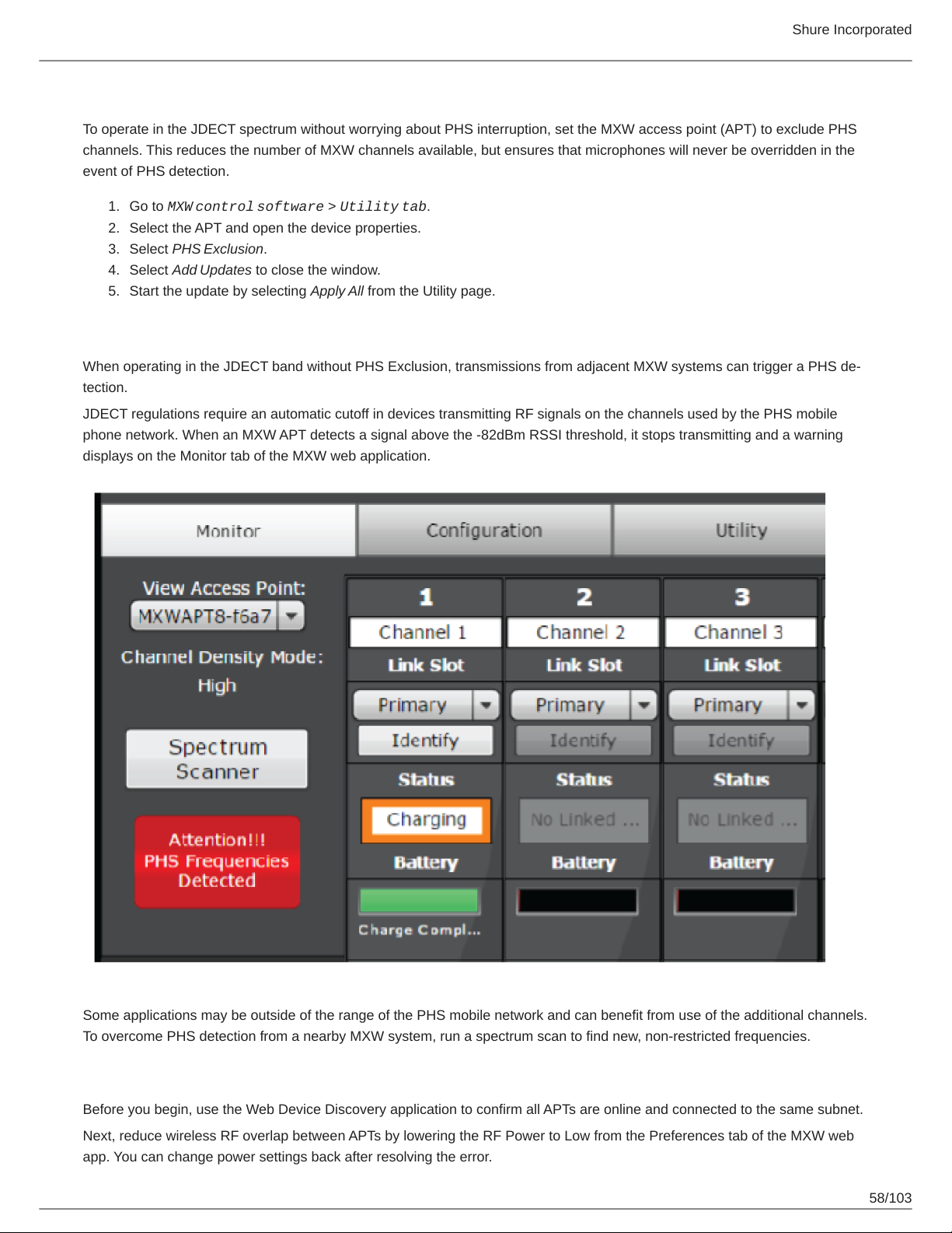
Shure Incorporated
Excluding PHS Bands
To operate in the JDECT spectrum without worrying about PHS interruption, set the MXW access point (APT) to exclude PHS
channels. This reduces the number of MXW channels available, but ensures that microphones will never be overridden in the
event of PHS detection.
1.
Go to MXW control software > Utility tab.
2.
Select the APT and open the device properties.
3.
Select PHS Exclusion.
4.
Select Add Updates to close the window.
5.
Start the update by selecting Apply All from the Utility page.
Identifying PHS Detection Errors
When operating in the JDECT band without PHS Exclusion, transmissions from adjacent MXW systems can trigger a PHS de
tection.
JDECT regulations require an automatic cutoff in devices transmitting RF signals on the channels used by the PHS mobile
phone network. When an MXW APT detects a signal above the -82dBm RSSI threshold, it stops transmitting and a warning
displays on the Monitor tab of the MXW web application.
Some applications may be outside of the range of the PHS mobile network and can benefit from use of the additional channels.
To overcome PHS detection from a nearby MXW system, run a spectrum scan to find new, non-restricted frequencies.
Resolving PHS Detection Errors
Before you begin, use the Web Device Discovery application to confirm all APTs are online and connected to the same subnet.
Next, reduce wireless RF overlap between APTs by lowering the RF Power to Low from the Preferences tab of the MXW web
app. You can change power settings back after resolving the error.
58/103
Page 59
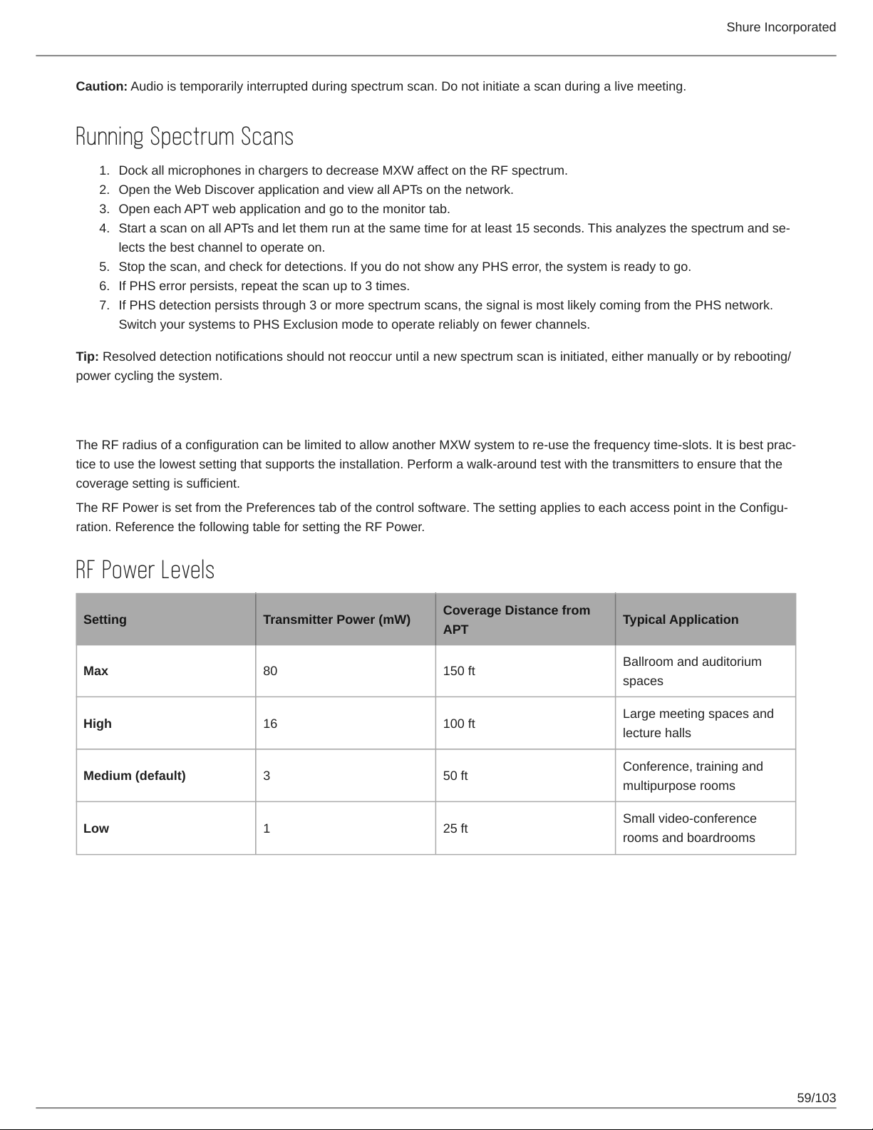
Shure Incorporated
Caution: Audio is temporarily interrupted during spectrum scan. Do not initiate a scan during a live meeting.
Running Spectrum Scans
1.
Dock all microphones in chargers to decrease MXW affect on the RF spectrum.
2.
Open the Web Discover application and view all APTs on the network.
3.
Open each APT web application and go to the monitor tab.
4.
Start a scan on all APTs and let them run at the same time for at least 15 seconds. This analyzes the spectrum and se
lects the best channel to operate on.
5.
Stop the scan, and check for detections. If you do not show any PHS error, the system is ready to go.
6.
If PHS error persists, repeat the scan up to 3 times.
7.
If PHS detection persists through 3 or more spectrum scans, the signal is most likely coming from the PHS network.
Switch your systems to PHS Exclusion mode to operate reliably on fewer channels.
Tip: Resolved detection notifications should not reoccur until a new spectrum scan is initiated, either manually or by rebooting/
power cycling the system.
Setting RF Power
The RF radius of a configuration can be limited to allow another MXW system to reuse the frequency timeslots. It is best prac
tice to use the lowest setting that supports the installation. Perform a walk-around test with the transmitters to ensure that the
coverage setting is sufficient.
The RF Power is set from the Preferences tab of the control software. The setting applies to each access point in the Configu
ration. Reference the following table for setting the RF Power.
RF Power Levels
Setting Transmitter Power (mW)
Max 80 150 ft
High 16 100 ft
Medium (default) 3 50 ft
Low 1 25 ft
Coverage Distance from
APT
Typical Application
Ballroom and auditorium
spaces
Large meeting spaces and
lecture halls
Conference, training and
multipurpose rooms
Small video-conference
rooms and boardrooms
59/103
Page 60
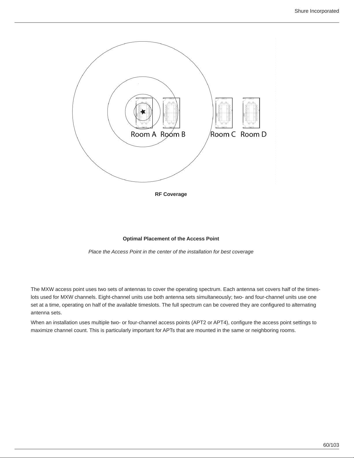
Shure Incorporated
RF Coverage
Optimal Placement of the Access Point
Place the Access Point in the center of the installation for best coverage
Using Multiple 2- or 4-Channel Access Points
The MXW access point uses two sets of antennas to cover the operating spectrum. Each antenna set covers half of the times
lots used for MXW channels. Eight-channel units use both antenna sets simultaneously; two- and four-channel units use one
set at a time, operating on half of the available timeslots. The full spectrum can be covered they are configured to alternating
antenna sets.
When an installation uses multiple two- or four-channel access points (APT2 or APT4), configure the access point settings to
maximize channel count. This is particularly important for APTs that are mounted in the same or neighboring rooms.
60/103
Page 61
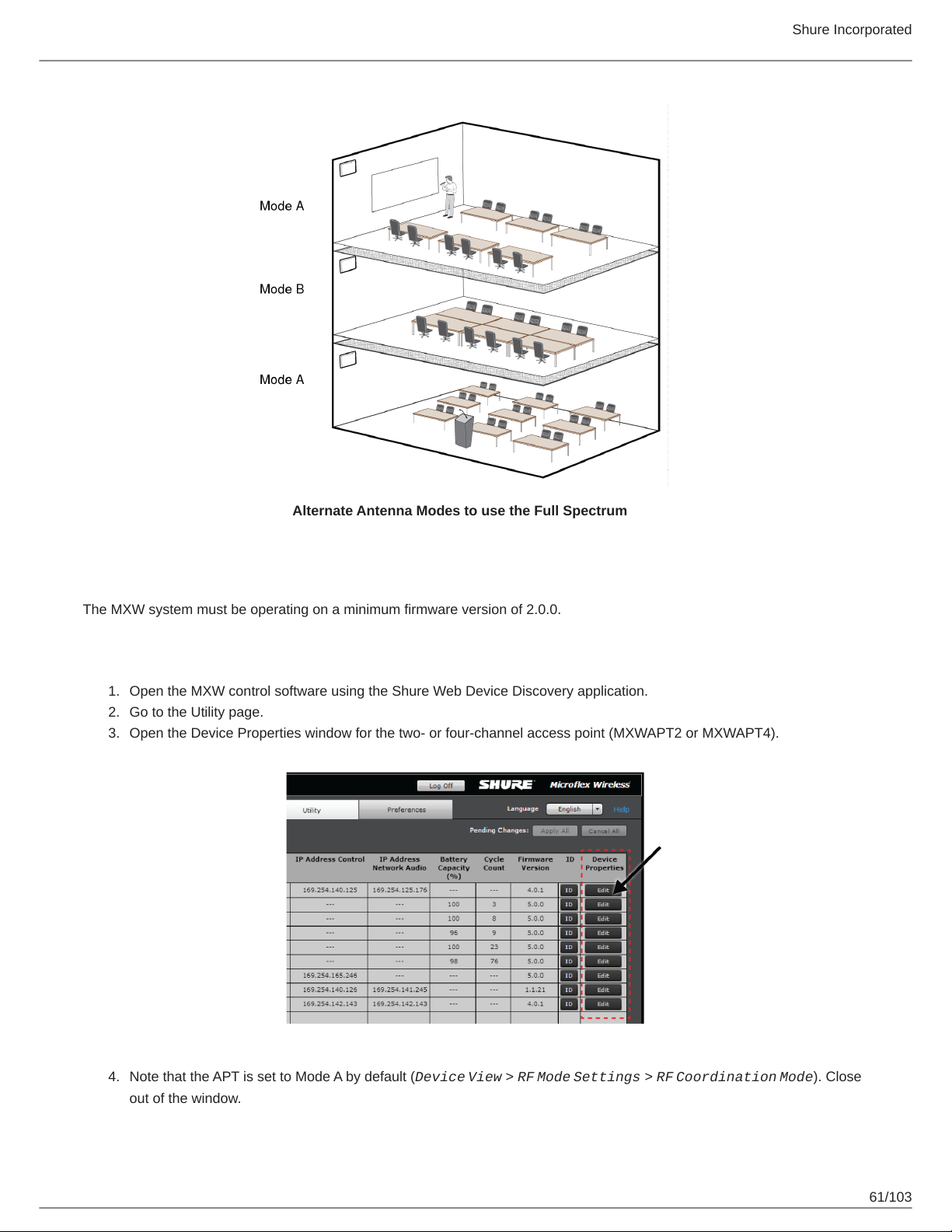
Shure Incorporated
Alternate Antenna Modes to use the Full Spectrum
Requirements
The MXW system must be operating on a minimum firmware version of 2.0.0.
Set Up
1.
Open the MXW control software using the Shure Web Device Discovery application.
2.
Go to the Utility page.
3.
Open the Device Properties window for the two- or four-channel access point (MXWAPT2 or MXWAPT4).
4.
Note that the APT is set to Mode A by default (Device View > RF Mode Settings > RF Coordination Mode). Close
out of the window.
61/103
Page 62
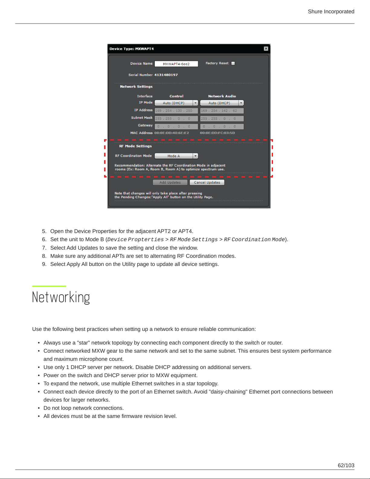
Shure Incorporated
5.
Open the Device Properties for the adjacent APT2 or APT4.
6.
Set the unit to Mode B (Device Propterties > RF Mode Settings > RF Coordination Mode).
7.
Select Add Updates to save the setting and close the window.
8.
Make sure any additional APTs are set to alternating RF Coordination modes.
9.
Select Apply All button on the Utility page to update all device settings.
Networking
Networking Best Practices
Use the following best practices when setting up a network to ensure reliable communication:
•
Always use a "star" network topology by connecting each component directly to the switch or router.
•
Connect networked MXW gear to the same network and set to the same subnet. This ensures best system performance
and maximum microphone count.
•
Use only 1 DHCP server per network. Disable DHCP addressing on additional servers.
•
Power on the switch and DHCP server prior to MXW equipment.
•
To expand the network, use multiple Ethernet switches in a star topology.
•
Connect each device directly to the port of an Ethernet switch. Avoid "daisy-chaining" Ethernet port connections between
devices for larger networks.
•
Do not loop network connections.
•
All devices must be at the same firmware revision level.
62/103
Page 63
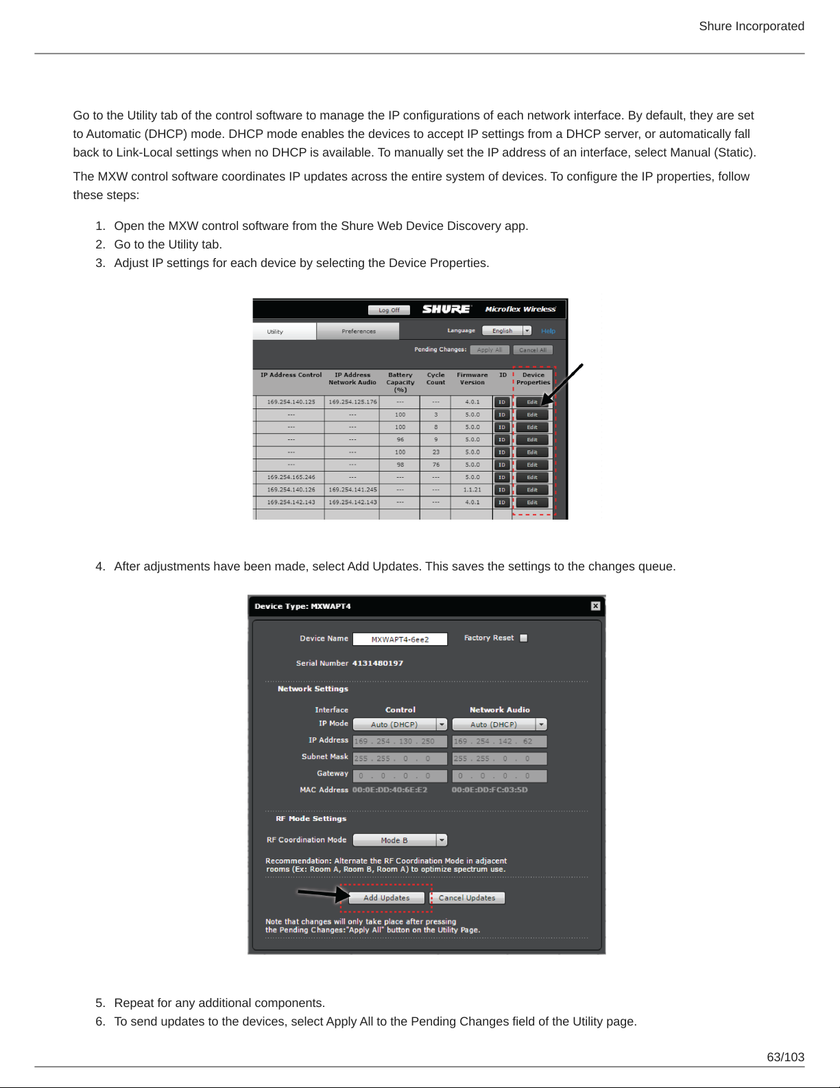
Shure Incorporated
Configuring IP Settings
Go to the Utility tab of the control software to manage the IP configurations of each network interface. By default, they are set
to Automatic (DHCP) mode. DHCP mode enables the devices to accept IP settings from a DHCP server, or automatically fall
back to Link-Local settings when no DHCP is available. To manually set the IP address of an interface, select Manual (Static).
The MXW control software coordinates IP updates across the entire system of devices. To configure the IP properties, follow
these steps:
1.
Open the MXW control software from the Shure Web Device Discovery app.
2.
Go to the Utility tab.
3.
Adjust IP settings for each device by selecting the Device Properties.
4.
After adjustments have been made, select Add Updates. This saves the settings to the changes queue.
5.
Repeat for any additional components.
6.
To send updates to the devices, select Apply All to the Pending Changes field of the Utility page.
63/103
Page 64
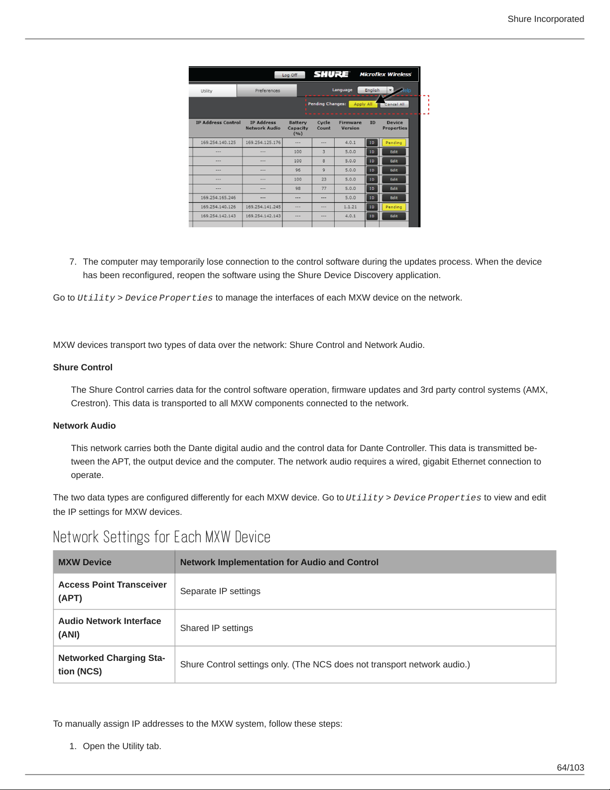
7.1.The computer may temporarily lose connection to the control software during the updates process. When the device
has been reconfigured, reopen the software using the Shure Device Discovery application.
Go to Utility > Device Properties to manage the interfaces of each MXW device on the network.
Shure Incorporated
Network Audio and Shure Control Data
MXW devices transport two types of data over the network: Shure Control and Network Audio.
Shure Control
The Shure Control carries data for the control software operation, firmware updates and 3rd party control systems (AMX,
Crestron). This data is transported to all MXW components connected to the network.
Network Audio
This network carries both the Dante digital audio and the control data for Dante Controller. This data is transmitted be
tween the APT, the output device and the computer. The network audio requires a wired, gigabit Ethernet connection to
operate.
The two data types are configured differently for each MXW device. Go to Utility > Device Properties to view and edit
the IP settings for MXW devices.
Network Settings for Each MXW Device
MXW Device Network Implementation for Audio and Control
Access Point Transceiver
(APT)
Separate IP settings
Audio Network Interface
(ANI)
Networked Charging Sta
tion (NCS)
Shared IP settings
Shure Control settings only. (The NCS does not transport network audio.)
Manually Assigning Static IP Address
To manually assign IP addresses to the MXW system, follow these steps:
Open the Utility tab.
64/103
Page 65
Shure Incorporated
2.
Select Edit to open the device properties window.
3.
Select the Manual (Static) IP Mode.
4.
Enter the IP settings
5.
Select the Add Updates button to queue the saved settings.
6.
Repeat for all additional components
7.
Finalize all updates by pressing the Apply All button from the Utility tab. All devices with pending changes will update.
Note: The control software may close if settings have been updated for the APT.
8.
Change the computer's IP address to match the subnet of the MXW equipment.
9.
Reopen the MXW control interface using the Shure Device Discovery application.
Advanced Setup
For more information on configuring advanced MXW networks, reference the Microflex Wireless Networking whitepaper locat
ed at www.shure.com.
Isolating Audio and Control Networks
When connecting to corporate or public networks, the MXW system can be configured to isolate audio network from the control
network. This protects the audio from distributing to the entire network and significantly decreases network traffic.
The MXW Audio Network Interface (ANI) can be set to Uplink mode to dedicate one of its network ports as a controlonly con
nection. Uplink mode blocks multicast traffic from Port 4 of the ANI, restricting network audio and Shure Discovery data.
Because the device will not show up in the Shure Device Discovery application, the IP address of the control software must be
recorded to access the server.
1.
Record the IP address of the ANI.
2.
Connect Port 4 of the ANI to the network.
3.
Use the Shure Web Device Discovery application to open the control software of the ANI.
4.
Go to the Preferences tab.
5.
Under the Network panel, change Port 4 Mode to Uplink.
Managing Large Systems on a Single Network
To manage large systems on a single network, lock the configuration after setting it up. This improves network performance
and stability, allowing a greater number of MXW systems to operate on the same network. This is especially important if there
are more than 15 total MXW APTs on a subnet.
Tip: Use an isolated network to set up or modify a configuration for best system performance.
1.
Connect the MXW equipment and a computer to an isolated network.
2.
Open the MXW browser interface to the Configuration tab.
3.
Create the configuration by associating each APT to the audio output device(s) and network charging station(s).
4.
Select the Lock Configuration box.
5.
Connect the components to the intended network.
6.
Repeat for additional configurations.
Operating the Control Software over Wi-Fi
When operating the MXW control software over WiFi, it’s important to set up the wireless router properly for best performance.
The MXW System employs several standardbased protocols that rely on multicast. WiFi treats broadcast and multicast pack
ets differently than general packets for backward compatibility reasons. In some cases, the Wi-Fi router will limit the multicast
packet transmission rate to a value that is too slow for GUI to properly operate.
65/103
Page 66
Shure Incorporated
Wi-Fi routers typically support 802.11b, 802.11a/g, and/or 802.11n standards. By default, many Wi-Fi routers are configured to
allow older 802.11b devices to operate over the network. In this configuration, these routers will automatically limit the multicast
data rates (or sometimes referred to as ‘basic rate’, or ‘management rate’) to 12Mbps.
Note: A Wi-Fi connection can only be used for the control software. Network audio cannot be transmitted over Wi-Fi.
Tip: For larger wireless microphone configurations, it’s recommended to increase the multicast transmission rate to provide adequate bandwidth to the MXW
control software.
Important: For best performance, use a Wi-Fi router that does not limit the multicast rate to 1-2 Mbps.
Shure recommends the following Wi-Fi router brands:
•
Cisco
•
Linksys
•
Apple
Dedicate a Device for Master Clock
Dante uses the IEEE 1588 Precision Time Protocol (PTP) to automatically select one device as the master clock for all Dante
devices on the network. PTP ensures that all devices are similarly clocked, which is critical for both audio delivery over the net
work and time-synced RF transmission over the wireless link. The master clock in an MXW System is the first MXW access
point that connects to the network. If several connect simultaneously, the access point with the lowest MAC address will be se
lected. Additional MXW components on the same network synchronize (slave) to this access point clock master.
When a master device shuts down or goes offline, the system will automatically begin selecting another master. During this se
lection time (up to 30 seconds), the entire system will NOT pass audio.
If the network setup or building management requires that devices are periodically shut down, you can manually select an ac
cess point as the Preferred Master device from Dante Controller software. This allows the installer to set up the system to en
sure that the master access point never shuts down during events.
Setting Latency
Latency is the amount of time for a signal to travel across the system to the outputs of a device. To account for variances in la
tency time between devices and channels, Dante has a predetermined selection of latency settings. When the same setting is
selected, it ensures that all Dante devices on the network are in sync.
The latency setting for Dante devices should be set according to the number of switches in the network. The MXW Audio Net
work Interface and Access Point both include an internal switch chip, which counts as a switch. For example, one network in
terface connected to an access point equals two switches.
Use Audinate's Dante Controller software to change the latency setting.
Latency Recommendations
Latency Setting Maximum Number of Switches
0.25 ms 3
0.5 ms (default) 5
1 ms 10
2 ms 10+
66/103
Page 67
Shure Incorporated
Connecting to an External Control System
The MXW System connects to an AMX or Crestron control system via the Ethernet. Use only one controller per system to
avoid messaging conflicts. For a comprehensive list of MXW command strings, visit: http://shure.custhelp.com/app/answers/
detail/a_id/5207
•
Connection: Ethernet (TCP/IP; MXW is the client)
•
Port: 2202
IP Ports and Protocols
Shure Control
Port TCP/UDP Protocol Description
21 tcp FTP Required for firmware updates (otherwise closed) Closed
22 tcp SSH Not supported Closed
23 tcp Telnet Standard console interface Closed
68 udp DHCP Dynamic Host Configuration Protocol Open
80* tcp HTTP Required to launch embedded web server Open
427 tcp/udp SLP Required for inter-device communication Open
443 tcp HTTPS Not supported Closed
161 tcp SNMP Not supported Closed
162 tcp SNMP Not supported Closed
843* tcp Flash Required for web application Open
2202 tcp ASCII Required for 3rd party control strings Open
5353 udp mDNS Required for device discovery Open
†
†
Factory De
fault
5568 udp SDT Required for inter-device communication Open
8023 tcp Telnet Debug console interface Password
8180* tcp Flash Required for web application Open
8181* tcp Flash Required for web application Open
8427 udp Multcast SLP Required for inter-device communication Open
64000 tcp Telnet Required for Shure firmware update Open
†
†
Dante Audio & Controller
Port TCP/UDP Protocol Description
162 udp SNMP Used by Dante
67/103
Page 68
Port TCP/UDP Protocol Description
Shure Incorporated
[319-320]* udp PTP Dante clocking
4321,
14336-14600
[4440, 4444,
4455]*
udp Dante Dante audio
udp Dante Dante audio routing
5353 udp mDNS Used by Dante
[8700-8706,
8800]*
udp Dante Dante Control and Monitoring
†
†
8751 udp Dante Dante Controller
16000-65536 udp Dante Used by Dante
*These ports must be open on the PC or control system to access the device through a firewall.
†
These protocols require multicast. Ensure multicast has been correctly configured for your network.
Packet Bridge
Packet bridge enables an external controller to obtain IP information from the control interface of a Shure device. To access the
packet bridge, an external controller must send a query packet over unicast UDP* to port 2203 on the Dante interface of the
Shure device.
1.
Send a UDP packet with a minimum 1-byte payload .
Note: The maximum accepted payload 140 bytes. Any content is allowed.
2.
The Shure device will send a response packet over unicast UDP to the controller, using a destination UDP port identical
to the source port of the query packet. The payload of the response packet follows this format:
Bytes Content
0-3 IP address, as 32-bit unsigned integer in network order
4-7
8-13 MAC address, as array of 6 bytes
Note: The Shure device should respond in less than one second on a typical network. If there is no response, try sending the query again after verify
ing the destination IP address and port number.
*UDP: User Datagram Protocol
Subnet mask, as 32bit unsigned integer in network or
der
68/103
Page 69
Shure Incorporated
Software
Shure Web Device Discovery Application
The Shure Web Device Discovery application is used to access the graphical user interface (GUI) of a Shure device. The GUI
opens in a web browser to provide comprehensive device management. Any computer networked to the device can access the
GUI with this application.
To use the application,
•
Double-click on a device or press the Open button to open a GUI.
•
Right-click on a device to copy its IP address or DNS name.
•
Select Network Settings to monitor the computer's network interface details.
1.
Refresh: Updates the list of devices.
2.
Network Settings: Displays the network interface details of the computer
3.
Select All: Selects all devices in the list.
4.
Open: Opens the GUI of a selected device in a browser window.
5.
Identify: Prompts the selected device to flash its LEDs for identification.
6.
Shure Website: Links to the Shure website.
7.
Help: Access the application help file or link to www.shure.com to view for updated versions of the application.
8.
Preferences: Determines whether the application launches the DNS name or the IP address of the selected device.
9.
Device List: List of Shure devices with an embedded GUI on the same network.
1.
Model: The device's model name.
2.
Name: Corresponds to the Device Name defined in the GUI.
3.
DNS Name: The domain name that is mapped to the device’s IP address. The DNS name will not change, even
if the IP address changes (making it useful as a hyperlink or bookmark in your browser).
4.
IP Address: The device’s assigned IP address. IP address settings can be changed in the device’s GUI.
5.
Network Audio Indicates which Network Audio protocols the device supports. See the product User Guide for
information on how to configure an audio network.
6.
Web UI:
Yes = The device has a graphical user interface that opens in a web browser.
No = The device does not have a user interface.
7.
Same Subnet:
Yes = The device and computer are set to the same subnet.
No = The device and computer are set to different subnets.
Unknown = The firmware of the device does not support this feature. Update the device firmware to view the
additional connection information with this app.
69/103
Page 70
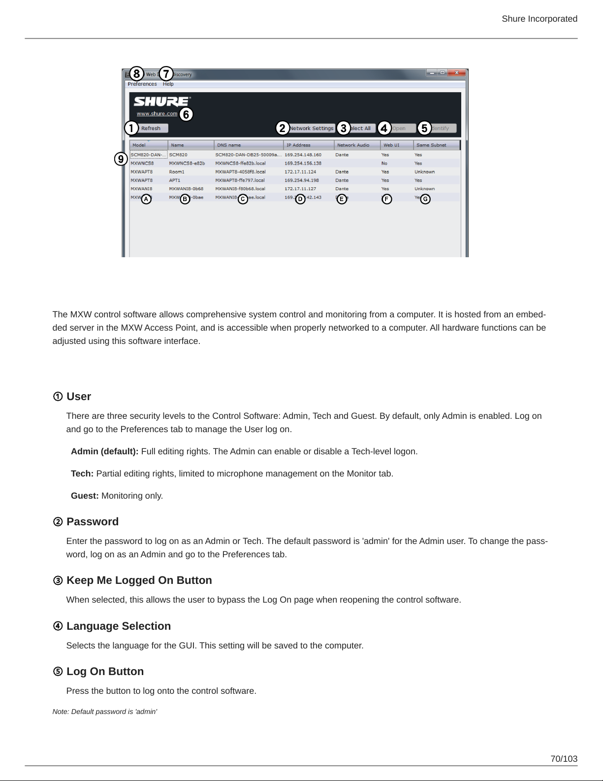
Shure Incorporated
MXW System Control Software
The MXW control software allows comprehensive system control and monitoring from a computer. It is hosted from an embed
ded server in the MXW Access Point, and is accessible when properly networked to a computer. All hardware functions can be
adjusted using this software interface.
Log On Page
① User
There are three security levels to the Control Software: Admin, Tech and Guest. By default, only Admin is enabled. Log on
and go to the Preferences tab to manage the User log on.
Admin (default): Full editing rights. The Admin can enable or disable a Tech-level logon.
Tech: Partial editing rights, limited to microphone management on the Monitor tab.
Guest: Monitoring only.
② Password
Enter the password to log on as an Admin or Tech. The default password is 'admin' for the Admin user. To change the pass
word, log on as an Admin and go to the Preferences tab.
③ Keep Me Logged On Button
When selected, this allows the user to bypass the Log On page when reopening the control software.
④ Language Selection
Selects the language for the GUI. This setting will be saved to the computer.
⑤ Log On Button
Press the button to log onto the control software.
Note: Default password is 'admin'
70/103
Page 71
Control Bar
① Tabs
◦
Monitor: Adjust microphone status and view RF spectrum availability.
◦
Configuration: Form groups of components
◦
Utility: View details and manage IP settings of each MXW device on the network
◦
Preferences: Assign microphone and system behavior
② Security Level
Displays the access level of the user: Administrator, Technician, or Guest.
③ Log Off
Logs the user out of the software.
④ Shure Link
Links to the Shure website at www.shure.com.
Shure Incorporated
⑤ Language Selection
Selects the language for the control software interface. This setting will be saved to the computer.
71/103
Page 72
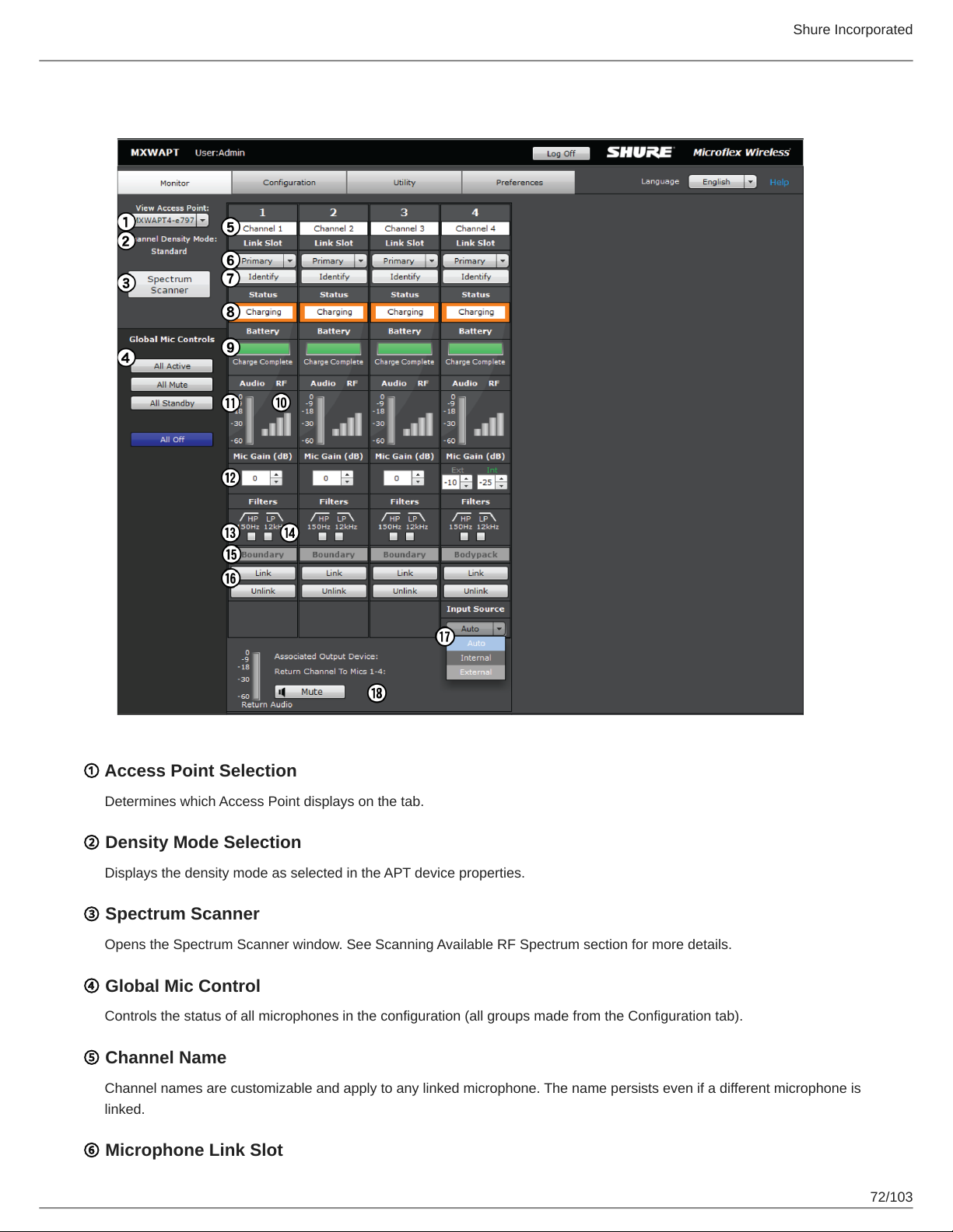
Monitor Tab
Shure Incorporated
① Access Point Selection
Determines which Access Point displays on the tab.
② Density Mode Selection
Displays the density mode as selected in the APT device properties.
③ Spectrum Scanner
Opens the Spectrum Scanner window. See Scanning Available RF Spectrum section for more details.
④ Global Mic Control
Controls the status of all microphones in the configuration (all groups made from the Configuration tab).
⑤ Channel Name
Channel names are customizable and apply to any linked microphone. The name persists even if a different microphone is
linked.
⑥ Microphone Link Slot
72/103
Page 73
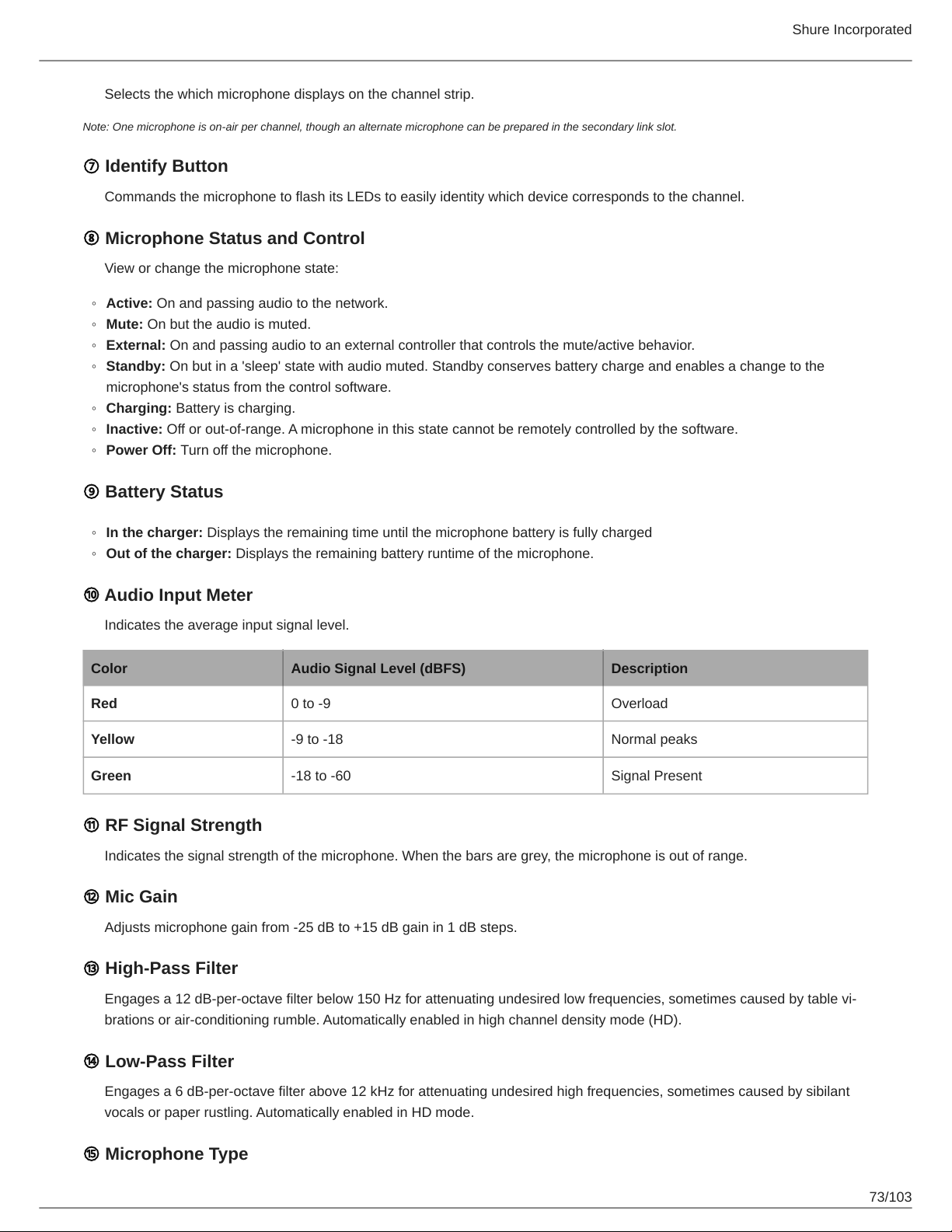
Selects the which microphone displays on the channel strip.
Note: One microphone is on-air per channel, though an alternate microphone can be prepared in the secondary link slot.
⑦ Identify Button
Commands the microphone to flash its LEDs to easily identity which device corresponds to the channel.
⑧ Microphone Status and Control
View or change the microphone state:
◦
Active: On and passing audio to the network.
◦
Mute: On but the audio is muted.
◦
External: On and passing audio to an external controller that controls the mute/active behavior.
◦
Standby: On but in a 'sleep' state with audio muted. Standby conserves battery charge and enables a change to the
microphone's status from the control software.
◦
Charging: Battery is charging.
◦
Inactive: Off or out-of-range. A microphone in this state cannot be remotely controlled by the software.
◦
Power Off: Turn off the microphone.
Shure Incorporated
⑨ Battery Status
◦
In the charger: Displays the remaining time until the microphone battery is fully charged
◦
Out of the charger: Displays the remaining battery runtime of the microphone.
⑩ Audio Input Meter
Indicates the average input signal level.
Color Audio Signal Level (dBFS) Description
Red 0 to -9 Overload
Yellow -9 to -18 Normal peaks
Green -18 to -60 Signal Present
⑪ RF Signal Strength
Indicates the signal strength of the microphone. When the bars are grey, the microphone is out of range.
⑫ Mic Gain
Adjusts microphone gain from -25 dB to +15 dB gain in 1 dB steps.
⑬ High-Pass Filter
Engages a 12 dBperoctave filter below 150 Hz for attenuating undesired low frequencies, sometimes caused by table vi
brations or air-conditioning rumble. Automatically enabled in high channel density mode (HD).
⑭ Low-Pass Filter
Engages a 6 dB-per-octave filter above 12 kHz for attenuating undesired high frequencies, sometimes caused by sibilant
vocals or paper rustling. Automatically enabled in HD mode.
⑮ Microphone Type
73/103
Page 74
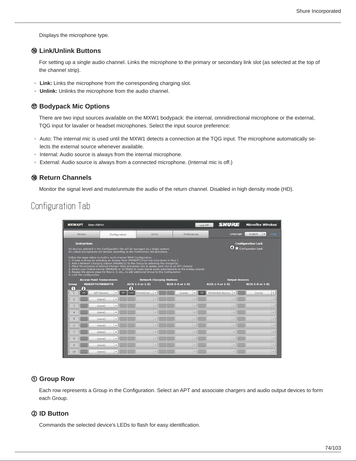
Shure Incorporated
Displays the microphone type.
⑯ Link/Unlink Buttons
For setting up a single audio channel. Links the microphone to the primary or secondary link slot (as selected at the top of
the channel strip).
◦
Link: Links the microphone from the corresponding charging slot.
◦
Unlink: Unlinks the microphone from the audio channel.
⑰ Bodypack Mic Options
There are two input sources available on the MXW1 bodypack: the internal, omnidirectional microphone or the external,
TQG input for lavalier or headset microphones. Select the input source preference:
◦
Auto: The internal mic is used until the MXW1 detects a connection at the TQG input. The microphone automatically se
lects the external source whenever available.
◦
Internal: Audio source is always from the internal microphone.
◦
External: Audio source is always from a connected microphone. (Internal mic is off.)
⑱ Return Channels
Monitor the signal level and mute/unmute the audio of the return channel. Disabled in high density mode (HD).
Configuration Tab
① Group Row
Each row represents a Group in the Configuration. Select an APT and associate chargers and audio output devices to form
each Group.
② ID Button
Commands the selected device's LEDs to flash for easy identification.
74/103
Page 75
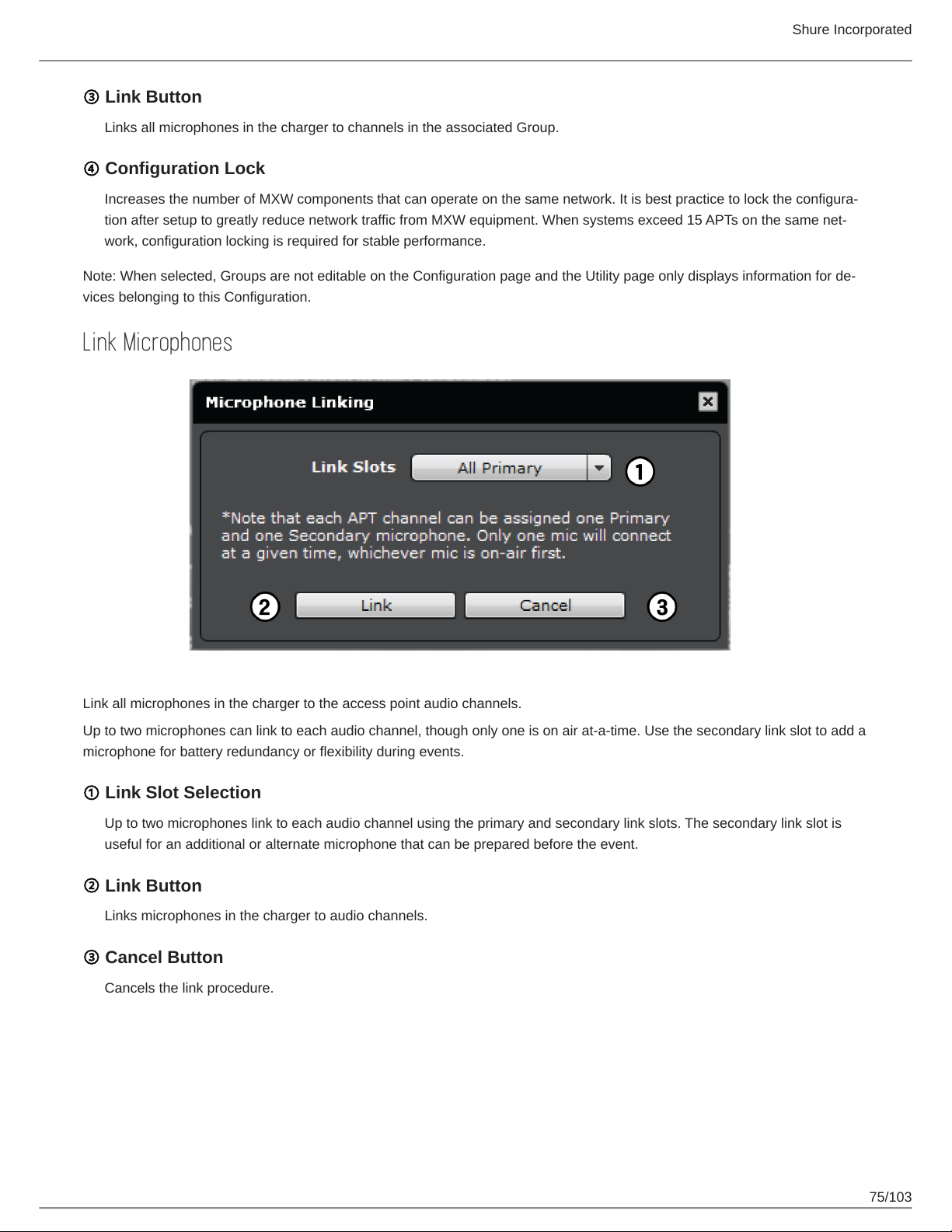
Shure Incorporated
③ Link Button
Links all microphones in the charger to channels in the associated Group.
④ Configuration Lock
Increases the number of MXW components that can operate on the same network. It is best practice to lock the configura
tion after setup to greatly reduce network traffic from MXW equipment. When systems exceed 15 APTs on the same net
work, configuration locking is required for stable performance.
Note: When selected, Groups are not editable on the Configuration page and the Utility page only displays information for de
vices belonging to this Configuration.
Link Microphones
Link all microphones in the charger to the access point audio channels.
Up to two microphones can link to each audio channel, though only one is on air at-a-time. Use the secondary link slot to add a
microphone for battery redundancy or flexibility during events.
① Link Slot Selection
Up to two microphones link to each audio channel using the primary and secondary link slots. The secondary link slot is
useful for an additional or alternate microphone that can be prepared before the event.
② Link Button
Links microphones in the charger to audio channels.
③ Cancel Button
Cancels the link procedure.
75/103
Page 76
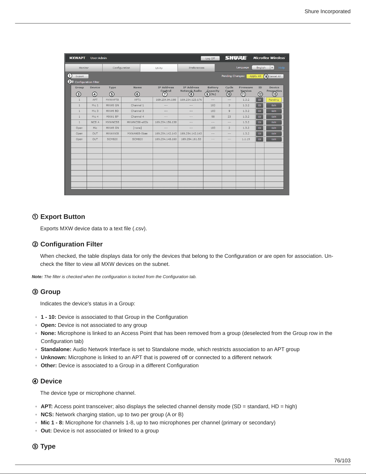
Utility Tab
Shure Incorporated
① Export Button
Exports MXW device data to a text file (.csv).
② Configuration Filter
When checked, the table displays data for only the devices that belong to the Configuration or are open for association. Un-
check the filter to view all MXW devices on the subnet.
Note: The filter is checked when the configuration is locked from the Configuration tab.
③ Group
Indicates the device's status in a Group:
◦
1 - 10: Device is associated to that Group in the Configuration
◦
Open: Device is not associated to any group
◦
None: Microphone is linked to an Access Point that has been removed from a group (deselected from the Group row in the
Configuration tab)
◦
Standalone: Audio Network Interface is set to Standalone mode, which restricts association to an APT group
◦
Unknown: Microphone is linked to an APT that is powered off or connected to a different network
◦
Other: Device is associated to a Group in a different Configuration
④ Device
The device type or microphone channel.
◦
APT: Access point transceiver; also displays the selected channel density mode (SD = standard, HD = high)
◦
NCS: Network charging station, up to two per group (A or B)
◦
Mic 1 - 8: Microphone for channels 1-8, up to two microphones per channel (primary or secondary)
◦
Out: Device is not associated or linked to a group
⑤ Type
76/103
Page 77
The device model number.
⑥ Name
Displays device name as defined in the Configuration tab or channel name as defined in the Monitor tab.
⑦ IP Address Control
Displays the IP Address of the control network interface (Shure control data).
⑧ IP Address Network Audio
Displays the IP Address of the Network Audio network interface (Dante digital audio data).
⑨ Battery Capacity
The microphone battery's percentage of charge capacity as compared to a new battery.
⑩ Cycle Count
Number of charge cycles logged by the battery.
Shure Incorporated
⑪ Firmware Version
Displays the device's firmware version.
⑫ ID Button
Sends a signal to the device to flash its LEDs for easy identification.
⑬ Device Properties
Opens a window for editing the properties of an individual device. The button displays yellow when the properties have
been edited for that device. The changes can be applied or cancelled from the Pending Changes Button on the Utility tab.
⑭ Pending Changes Buttons
These buttons apply or cancel any changes made to the device properties:
◦
Apply All: Confirms and executes all updates to device properties. At this time, the computer may lose connection to the
control software.
◦
Cancel All: Clears all pending changes to the device properties.
Device Properties
Edit the settings for each device by opening the Device Properties window from the Utility tab. Device properties are edited in
dividually, but are uploaded to the devices in bulk by selecting the Apply All button from the Utility tab. This ensures that the
changes are deployed properly across the network.
Some settings vary depending on the device capabilities.
77/103
Page 78
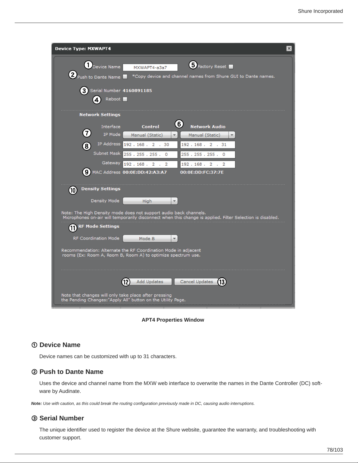
Shure Incorporated
APT4 Properties Window
① Device Name
Device names can be customized with up to 31 characters.
② Push to Dante Name
Uses the device and channel name from the MXW web interface to overwrite the names in the Dante Controller (DC) soft
ware by Audinate.
Note: Use with caution, as this could break the routing configuration previously made in DC, causing audio interruptions.
③ Serial Number
The unique identifier used to register the device at the Shure website, guarantee the warranty, and troubleshooting with
customer support.
78/103
Page 79
Shure Incorporated
④ Reboot
The unit performs a power cycle.
⑤ Factory Reset
Resets the device to default settings, clearing any MXW Group and Link associations. The password to access the control
software will reset to admin.
⑥ Network Interface(s)
View and adjust IP settings for the device's network interface(s). Network settings are different for each device. See the
Networking section for configuring each MXW device.
◦
Control: Shure control (software interface operation, firmware updates, Shure Device Discovery application).
◦
Network Audio: Dante network audio (digital audio networking and Dante software).
⑦ IP Mode
Sets IP mode of the selected network interface:
◦
Auto (DHCP): For automatic assignment of IP addresses.
◦
Manual (Static): For Static IP addresses.
⑧ IP Settings
View and edit the IP Address, Subnet Mask, and Gateway for each network interface.
⑨ MAC Address
The network interface's unique identification.
⑩ Density Mode
Sets the density mode set on the APT:
◦
Standard density (default)
◦
High density (doubles the available channels)
⑪ RF Mode Settings
For APT2 and APT4 installed in adjacent rooms, alternate modes (Mode A, Mode B) to get the best RF performance.
⑫ Add Updates
Select Add Updates to save the device changes to the control software. All device properties are updated simultaneously
from the Utility tab. Once saved, the device will show Pending under the Properties column.
⑬ Cancel Updates
Remove any changes made to the device properties.
79/103
Page 80
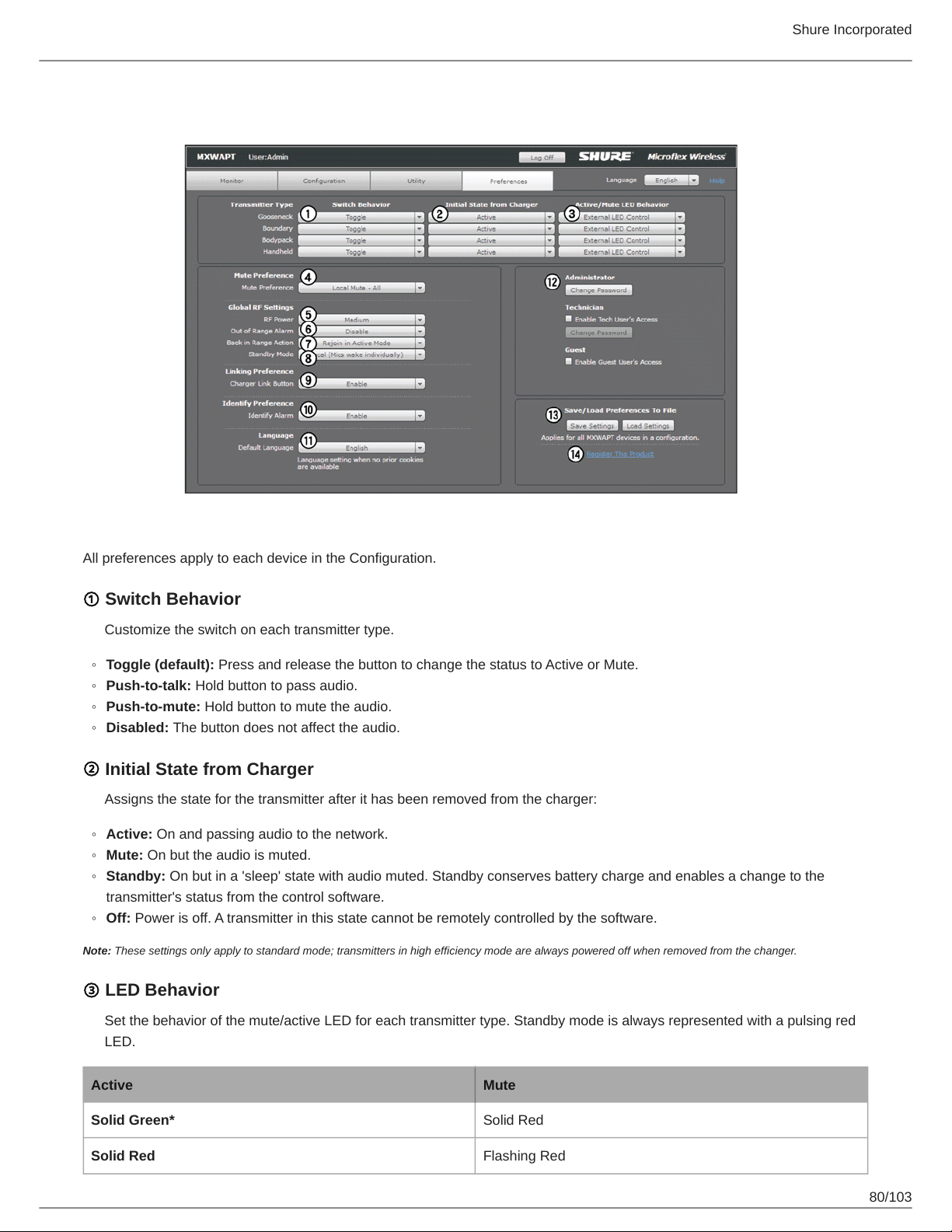
Preferences Tab
Shure Incorporated
All preferences apply to each device in the Configuration.
① Switch Behavior
Customize the switch on each transmitter type.
◦
Toggle (default): Press and release the button to change the status to Active or Mute.
◦
Push-to-talk: Hold button to pass audio.
◦
Push-to-mute: Hold button to mute the audio.
◦
Disabled: The button does not affect the audio.
② Initial State from Charger
Assigns the state for the transmitter after it has been removed from the charger:
◦
Active: On and passing audio to the network.
◦
Mute: On but the audio is muted.
◦
Standby: On but in a 'sleep' state with audio muted. Standby conserves battery charge and enables a change to the
transmitter's status from the control software.
◦
Off: Power is off. A transmitter in this state cannot be remotely controlled by the software.
Note: These settings only apply to standard mode; transmitters in high efficiency mode are always powered off when removed from the changer.
③ LED Behavior
Set the behavior of the mute/active LED for each transmitter type. Standby mode is always represented with a pulsing red
LED.
Active Mute
Solid Green* Solid Red
Solid Red Flashing Red
80/103
Page 81
Active Mute
Solid Red Off
External LED Control
*Not available for MX400R series gooseneck microphones
④ Mute Preference
◦
Local Mute - Individual (default): Each transmitter is muted individually.
◦
Local Mute - All: All transmitters mute when any transmitter is muted.
◦
External Mute: Transmitter audio is on, and muted from a 3rd-party controller.
⑤ RF Power
Determines the RF coverage of an access point.
◦
Low: 25 ft (1mW)
◦
Medium: 50 ft (3 mW)
◦
Medium High: 100 ft (16 mW)
◦
Max: 150 ft (80 mW)
Shure Incorporated
⑥ Out of Range Alarm
When enabled, a transmitter will audibly beep when it is taken out of the RF coverage area. (Disabled by default.)
⑦ Back in Range Action
Transmitters can be set to automatically activate (default) or mute when they re-enter the RF coverage area.
⑧ Standby Mode
◦
Local (default): Transmitter can individually be activated.
◦
Global: All transmitters are activated at the same time from Standby mode.
⑨ Linking Preference
The Link procedure can be restricted to the control software by disabling the hardware Link button on the Networked
Charging Station. By default, the Link button is enabled.
⑩ Identity Preference
Determines the way the transmitter responds when it is identified from the control software:
◦
Enabled: Beeps with flashing LEDs
◦
Disabled: Flashing LEDs only (no sound)
⑪ Language
Determines the language of the control software.
⑫ Password Setup
The default password for the device is 'admin'. The following describes access rights for each logon:
Admin (default): Full monitoring and editing access. The Admin can enable or disable the Tech- and Guest-level logon.
81/103
Page 82
Shure Incorporated
Tech: Monitoring with limited editing access.
Guest: Monitoring only.
⑬ Save/Load Preferences
Saves the preferences of the Configuration as a file to the computer. The file can be loaded and will overwrite the settings
for all devices in the Configuration.
⑭ Register the Product Link
Links to Shure website for product registration.
Control Software for the MXW Audio Network Interface
The MXW Audio Network Interface features a control software to mange the analog inputs and outputs of the MXW system, in
addition to the 4-port gigabit switch on the back panel of the network interface.
By default, all MXW devices have the password 'admin' applied to the control software. When logging in for the first time, enter
'admin' into the field to log on as the administrator. The password can be changed from the Preferences tab.
Note: For optimal system performance, the control software should not be open to more than seven tabs or windows.
Log On Page
① User
There are three security levels to the Control Software: Admin, Tech and Guest. By default, only Admin is enabled. Log on
and go to the Preferences tab to manage the User log on.
Admin (default): Full editing rights. The Admin can enable or disable a Tech-level logon.
Tech: Partial editing rights, limited to microphone management on the Monitor tab.
Guest: Monitoring only.
② Password
Enter the password to log on as an Admin or Tech. The default password is 'admin' for the Admin user. To change the pass
word, log on as an Admin and go to the Preferences tab.
③ Keep Me Logged On Button
When selected, this allows the user to bypass the Log On page when reopening the control software.
④ Language Selection
Selects the language for the GUI. This setting will be saved to the computer.
⑤ Log On Button
Press the button to log onto the control software.
Note: Default password is 'admin'
Control Bar
① Tabs
The software has an Inputs/Outputs tab for managing audio and a Preferences tab for system configurations.
82/103
Page 83
② Identify Button
This button sends a command to the hardware to flash front-panel LEDs for easy identification.
③ Security Level
Displays the access level of the user: Administrator, Technician, or Guest.
④ Log Off
Logs the user out of the software.
⑤ Language Selection
Selects the language for the control software interface. This setting will be saved to the computer.
Inputs/Outputs Tab
① Channel Name
Channel name is customizable by clicking in the text box. Names can be up to 12 characters long.
Shure Incorporated
② Input Gain Setting (A, B)
Sets the analog input gain level: Line (default) or Aux.
③ Input Audio Meter
Displays input audio levels prior to the analog-to-digital converter.
④ Mute Button
Mutes or unmutes the channel's audio. The button illuminates red when a channel is muted.
⑤ Output Gain
Sets the output gain level.
⑥ Output Audio Meter
Displays output audio levels prior to the digital-to-analog converter.
⑦ Attenuation
Output attenuation is adjustable in 1 dB increments.
⑧ Notes
Save project notes here, such as installation dates or IP information.
Preferences Tab
① Language
Selects the language for the control software when the ANI is in Standalone Mode. In Standalone Network mode, this is de
fined in the MXW System control software.
② Device Serial Number
Displays the device serial number.
83/103
Page 84
Shure Incorporated
③ Firmware Version
Displays the current firmware version of the device.
④ Reset Button
Reboots the device with factory default settings.
⑤ Register This Product Link
Click to register the device at www.shure.com to receive product and software updates.
⑥ Audio Routing Mode
◦
MXW Mode: Enables automatic channel routing when the device is a part of an MXW group (assigned from the MXW Sys
tem control software).
◦
Standalone Mode: Channels must be routed manually with Dante Controller software.
⑦ Device Name
Device names can be customized with up to 31 characters, except '=','.' or '@'.
⑧ Addressing Mode
Auto: IP settings are Link-Local or automatically accepted from a DHCP server.
Manual: IP settings (IP Address, Subnet Mask, and Gateway) are static and are entered manually.
⑨ MAC Address
Unique identifier assigned to each network interface.
⑩ Port 4 Mode
Configures the Port 4 of the network interface:
◦
Switched Mode (default): Full Ethernet support on port 4.
◦
Uplink Mode: Only control data is transported. Multicast traffic for Dante digital audio and the Shure Web Device Discov
ery application is restricted.
⑪ Front Panel Lockout
Disables the front panel controls on the hardware. Channels can still be selected for monitoring at the headphone jack.
⑫ Password
The default password for the device is 'admin'.
◦
Admin (default): Full editing rights. The Admin can enable or disable a Tech-level logon.
◦
Tech: Rights are limited to the Inputs/Outputs page (hardware functions only).
◦
Guest: Monitoring only.
Dante Software by Audinate
Audinate software provides additional function and control of the Dante digital audio network. Visit Audinate's website for in
structions for download and installation.
84/103
Page 85
Shure Incorporated
Dante Controller
Dante Controller (DC) is free software by Audinate that is used to configure and manage a network of Dante devices. Use it to
route channels between Dante-enabled devices and to monitor the status of the device, clock, and network.
Important: The MXWAPT must be the Dante clock master for the network. Do not change the clock master from the MXWAPT
(default selection) to another device.
Note: DC software is not required for routing audio within the MXW system. Use caution when using DC, as changing settings may interfere with MXW system
functionality.
Dante Virtual Soundcard
Dante Virtual Soundcard (DVS) acts as an audio driver used to monitor and record digital audio without additional equipment.
DVS uses a computer's standard Ethernet ports to transmit and receive up to 64 channels from any Dante enabled device on
the same network.
Firmware Updates
Firmware is embedded software in each component that controls functionality. Periodically, new versions of firmware are devel
oped to incorporate additional features and enhancements. To take advantage of design improvements, new versions of the
firmware can be uploaded and installed using the Shure Update Utility. Download the software from www.shure.com.
Perform the following steps to update the firmware:
CAUTION! Ensure the device has a stable network connection during the update. Do not turn off the device until the update is complete.
1.
Connect the device and computer to the same network (set to the same subnet).
◦
To update MXW transmitters, place them in the MXW Networked Charging Station that is connected to the same
network.
◦
If the MXW Audio Network Interface is connected via Port 4, ensure that the Network mode is set to Switched mode
(default) from the Preferences tab of the ANI control software.
2.
Open the Shure Update Utility application.
3.
Click Check For Updates... button to view new firmware versions available for download.
4.
Select the desired firmware and press Downloadto download it to the Firmware Library.
5.
From the Update Devices tab, select the new firmware and press Send Updates... to begin the firmware update, which
overwrites the existing firmware on the device.
Firmware Release Requirements
Microflex Wireless devices comprise a network with multiple communications protocols that work together to ensure proper op
eration. The recommended best practice is that all MXW devices are on an identical release. To view the firmware of each
MXW device on the network, open the Utility page of the MXW control software.
The format for Shure device’s firmware is MAJOR.MINOR.PATCH. (Ex. 1.6.2 where 1 is the Major firmware level, 6 is the Mi
nor firmware level, and 2 is the Patch firmware level.) At minimum, devices that operate on the same subnet should have
identical MAJOR and MINOR release numbers.
Troubleshooting
The following table offers typical solutions when troubleshooting the Microflex Wireless System.
85/103
Page 86
Audio
Problem Indicator Solution
Check cables
Check that transmitters are on and channels are un-muted
Check that the input meters are OK on the Monitor tab of the MXW control
software. Attenuate if the channel is clipping.
Check the output meters on the Audio Network Interface (ANI) front panel
and in the ANI control software. Use headphones to listen to the audio
from the ANI. Attenuate if the channel is clipping.
Check that the output level of the ANI matches the input of the connecting
equipment
Verify APT is not performing a spectrum scan
Ensure all devices are on and have a stable network connection
Use Dante Controller software (DC) to verify channel subscriptions
No or distort
ed audio
Network Audio
LED on the Au
dio Network In
terface or
SCM820
Green
Flashing
Green
Shure Incorporated
Red Check master clock in DC (an MXWAPT must be master clock)
Place the device in a Group to automatically route the audio
Audio is cut
ting in an out
(intermittent)
Off
Audio is intermittent
Ensure the subnet of the Access Point Transceiver's network audio set
tings match the subnet of the Audio Network Interface
Perform a Spectrum Scan to monitor RF interference
Decrease channel count to verify if system is overloading the RF spectrum
System Setup and MXW Groups
Problem Indicator Solution
Check that devices are powered and connected to the same network and
subnet)
Can't asso
ciate compo
nent to a
Group
Device dropdown not dis
playing the desired compo
nent in the Group row on the
Configuration tab
Open the Utility tab of the MXW Control Software and uncheck the Con
figuration Filter to display all MXW devices on the network. If the device
shows up as "OTHER", then it is part of another Configuration.
Un-associate the component by selecting 'none' from the Group row in the
other Configuration
Perform a factory reset on the device to clear any association
86/103
Page 87
Network and Device Monitoring
Problem Indicator Solution
Ensure the devices are powered
Ensure PC and equipment are on the same network and set to the same
subnet
Can't Connect
to the Control
Software from
a PC
Device not appearing in
Shure Web Device Discovery
application
Turn off other network interfaces not used to connect to the device (includ
ing WiFi)
Check that DHCP server is functioning (if applicable)
Ensure Bonjour is running on the PC
If connected via Port 4 of the Audio Network Interface (ANI), ensure it is
set to Switched Mode
For the Networked Charging Station, ensure that it is not in High Efficiency
Mode (Link LED indicator illuminated blue)
Shure Incorporated
® ®
Control Soft
ware is taking
a long time to
load
Control Soft
ware is per
forming poor
ly
Charger is not
discovered by
the Control
Software
Web browser cannot connect
to the control interface
Indicators are moving slowly
or not displaying in real time
The charger does not appear
in the UI
Download latest version of Adobe Flash
Ensure PC and device are on the same network and subnet
Check that Windows firewall settings are not blocking Shure software
Set the router to not send default gateway as a part of DHCP
Set the Shure Web Device Discovery application to open by IP address
Manually set the computer to a static IP address on the same network as
the device
Reduce the number of windows or tabs that are open to the same Config
uration
See Network section for properly setting up the network
Ensure that the MXWNCS charger is not in High Efficiency Mode (solid
blue Microphone Link LED)
Additional Resources
For additional Troubleshooting assistance or further information on complex installations, contact Shure to speak with a support
representative. In the Americas region, call Systems Support group at 847-600-8440. For users in other locations, go to
www.shure.com to find support contact for your region.
For digital audio networking help, advanced networking guidelines and Dante software troubleshooting, visit Audinate's website
at www.audinate.com.
Factory Reset
If a device isn't appearing on the network after trying troubleshooting methods, perform a reset on the specific hardware to re
turn the device to default settings. Factory default settings are designed for automatic compatibility with other Shure networked
devices.
Note: A factory reset will clear any MXW Group and Link associations. The password to access the software will reset to admin.
87/103
Page 88
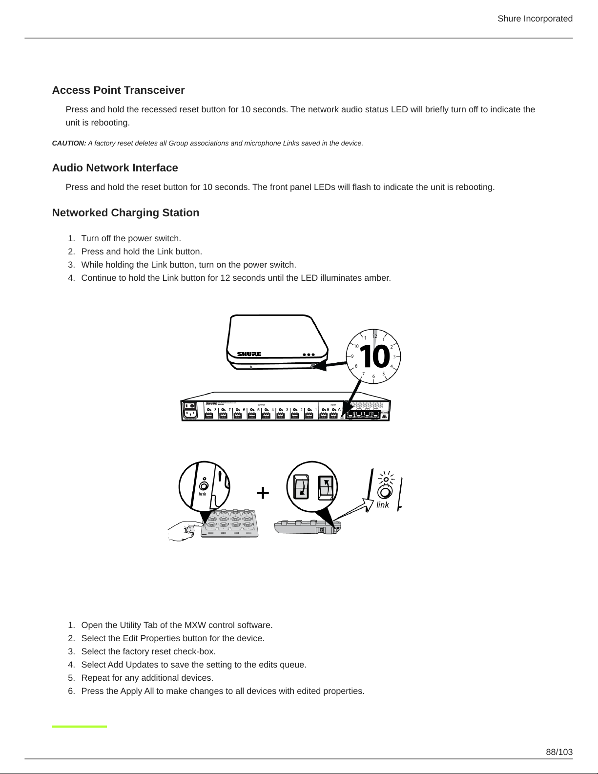
Shure Incorporated
From the Hardware
Access Point Transceiver
Press and hold the recessed reset button for 10 seconds. The network audio status LED will briefly turn off to indicate the
unit is rebooting.
CAUTION: A factory reset deletes all Group associations and microphone Links saved in the device.
Audio Network Interface
Press and hold the reset button for 10 seconds. The front panel LEDs will flash to indicate the unit is rebooting.
Networked Charging Station
1.
Turn off the power switch.
2.
Press and hold the Link button.
3.
While holding the Link button, turn on the power switch.
4.
Continue to hold the Link button for 12 seconds until the LED illuminates amber.
From the Control Software
1.
Open the Utility Tab of the MXW control software.
2.
Select the Edit Properties button for the device.
3.
Select the factory reset check-box.
4.
Select Add Updates to save the setting to the edits queue.
5.
Repeat for any additional devices.
6.
Press the Apply All to make changes to all devices with edited properties.
88/103
Page 89
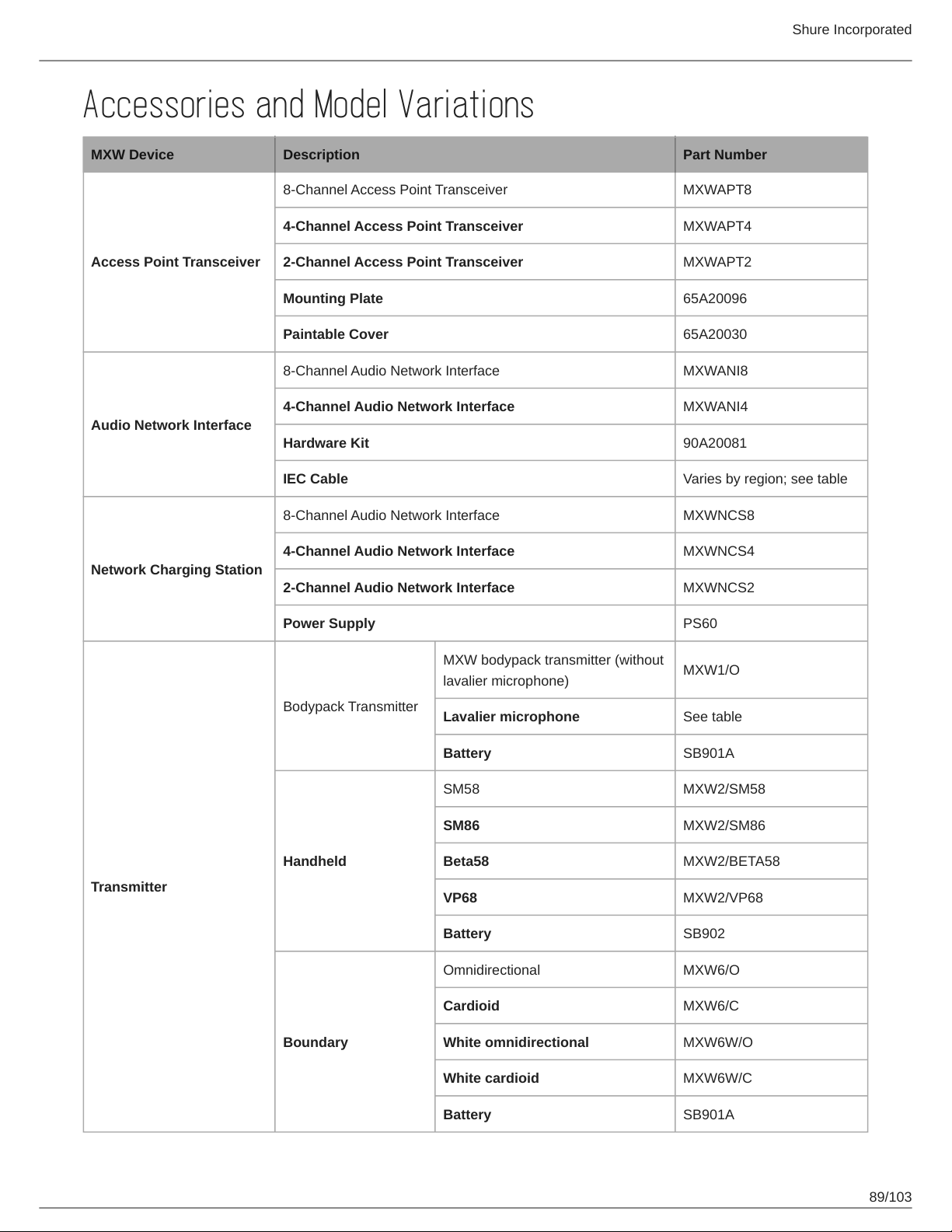
Accessories and Model Variations
MXW Device Description Part Number
8-Channel Access Point Transceiver MXWAPT8
4-Channel Access Point Transceiver MXWAPT4
Shure Incorporated
Access Point Transceiver
Audio Network Interface
Network Charging Station
2-Channel Access Point Transceiver MXWAPT2
Mounting Plate 65A20096
Paintable Cover 65A20030
8-Channel Audio Network Interface MXWANI8
4-Channel Audio Network Interface MXWANI4
Hardware Kit 90A20081
IEC Cable Varies by region; see table
8-Channel Audio Network Interface MXWNCS8
4-Channel Audio Network Interface MXWNCS4
2-Channel Audio Network Interface MXWNCS2
Power Supply PS60
Bodypack Transmitter
MXW bodypack transmitter (without
lavalier microphone)
Lavalier microphone See table
MXW1/O
Transmitter
Handheld
Boundary
Battery SB901A
SM58 MXW2/SM58
SM86 MXW2/SM86
Beta58 MXW2/BETA58
VP68 MXW2/VP68
Battery SB902
Omnidirectional MXW6/O
Cardioid MXW6/C
White omnidirectional MXW6W/O
White cardioid MXW6W/C
Battery SB901A
89/103
Page 90
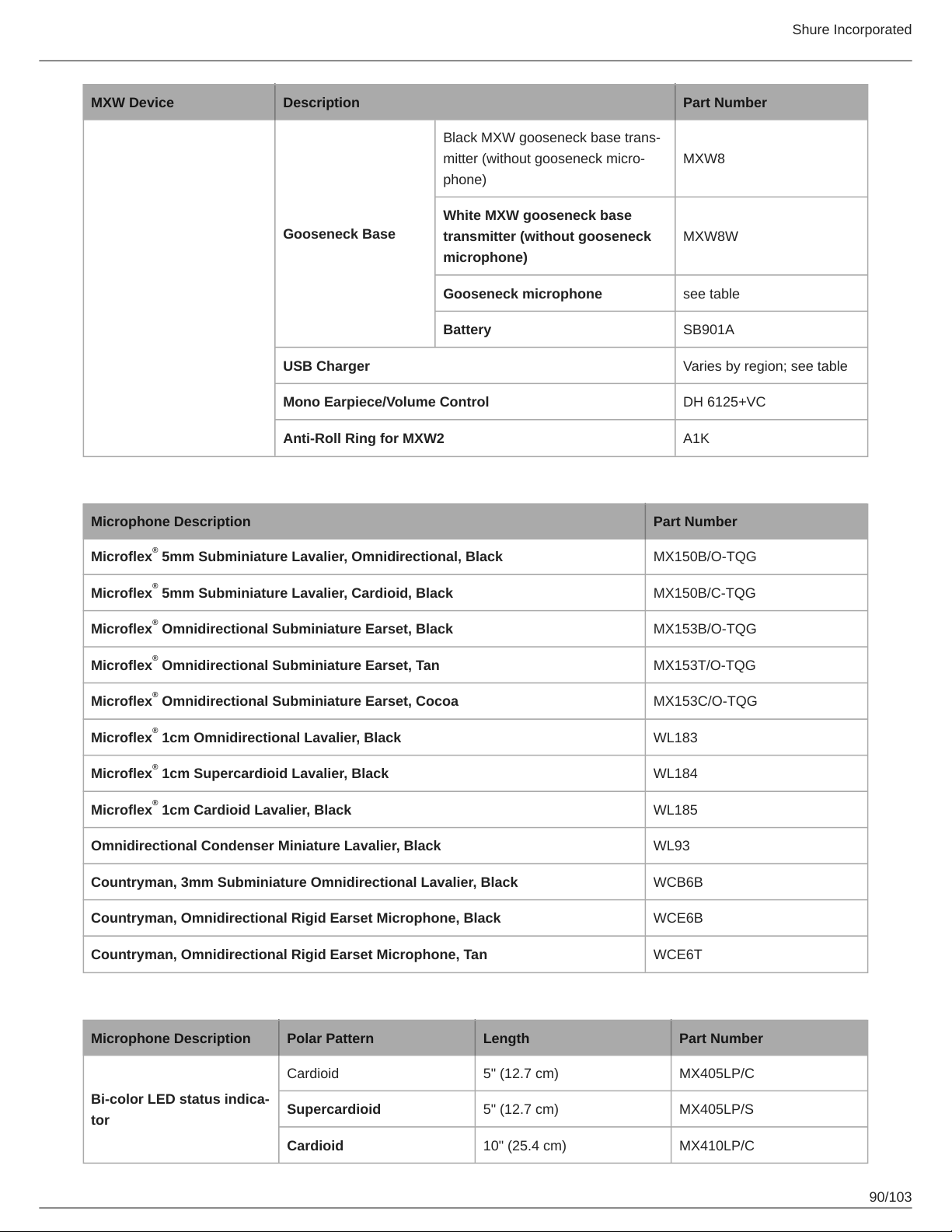
MXW Device Description Part Number
Black MXW gooseneck base trans
mitter (without gooseneck micro
MXW8
phone)
White MXW gooseneck base
Gooseneck Base
transmitter (without gooseneck
MXW8W
microphone)
Gooseneck microphone see table
Battery SB901A
USB Charger Varies by region; see table
Mono Earpiece/Volume Control DH 6125+VC
Anti-Roll Ring for MXW2 A1K
Shure Incorporated
Lavalier Options
Microphone Description Part Number
Microflex 5mm Subminiature Lavalier, Omnidirectional, Black MX150B/O-TQG
Microflex 5mm Subminiature Lavalier, Cardioid, Black MX150B/C-TQG
Microflex Omnidirectional Subminiature Earset, Black MX153B/O-TQG
Microflex Omnidirectional Subminiature Earset, Tan MX153T/O-TQG
Microflex Omnidirectional Subminiature Earset, Cocoa MX153C/O-TQG
Microflex 1cm Omnidirectional Lavalier, Black WL183
Microflex 1cm Supercardioid Lavalier, Black WL184
Microflex 1cm Cardioid Lavalier, Black WL185
Omnidirectional Condenser Miniature Lavalier, Black WL93
Countryman, 3mm Subminiature Omnidirectional Lavalier, Black WCB6B
Countryman, Omnidirectional Rigid Earset Microphone, Black WCE6B
®
®
®
®
®
®
®
®
Countryman, Omnidirectional Rigid Earset Microphone, Tan WCE6T
Gooseneck Options
Microphone Description Polar Pattern Length Part Number
Cardioid 5" (12.7 cm) MX405LP/C
Bicolor LED status indica
tor
Supercardioid 5" (12.7 cm) MX405LP/S
Cardioid 10" (25.4 cm) MX410LP/C
90/103
Page 91
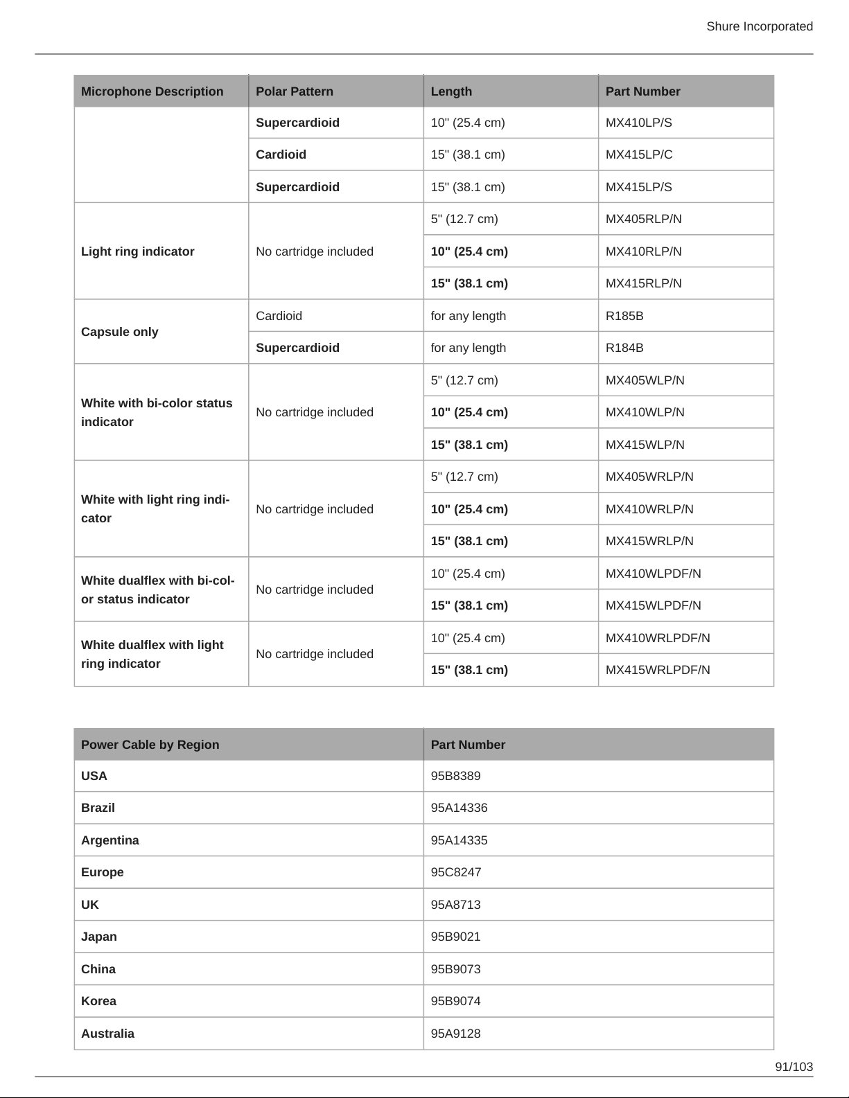
Microphone Description Polar Pattern Length Part Number
Supercardioid 10" (25.4 cm) MX410LP/S
Cardioid 15" (38.1 cm) MX415LP/C
Supercardioid 15" (38.1 cm) MX415LP/S
5" (12.7 cm) MX405RLP/N
Shure Incorporated
Light ring indicator No cartridge included
Cardioid for any length R185B
Capsule only
Supercardioid for any length R184B
White with bi-color status
indicator
White with light ring indi
cator
White dualflex with bicol
or status indicator
White dualflex with light
ring indicator
No cartridge included
No cartridge included
No cartridge included
No cartridge included
10" (25.4 cm) MX410RLP/N
15" (38.1 cm) MX415RLP/N
5" (12.7 cm) MX405WLP/N
10" (25.4 cm) MX410WLP/N
15" (38.1 cm) MX415WLP/N
5" (12.7 cm) MX405WRLP/N
10" (25.4 cm) MX410WRLP/N
15" (38.1 cm) MX415WRLP/N
10" (25.4 cm) MX410WLPDF/N
15" (38.1 cm) MX415WLPDF/N
10" (25.4 cm) MX410WRLPDF/N
15" (38.1 cm) MX415WRLPDF/N
IEC Power Cable
Power Cable by Region Part Number
USA 95B8389
Brazil 95A14336
Argentina 95A14335
Europe 95C8247
UK 95A8713
Japan 95B9021
China 95B9073
Korea 95B9074
Australia 95A9128
91/103
Page 92
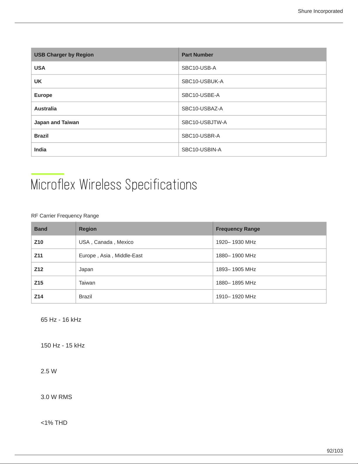
USB Charger
USB Charger by Region Part Number
USA SBC10-USB-A
UK SBC10-USBUK-A
Europe SBC10-USBE-A
Australia SBC10-USBAZ-A
Japan and Taiwan SBC10-USBJTW-A
Brazil SBC10-USBR-A
India SBC10-USBIN-A
Shure Incorporated
Microflex Wireless Specifications
System
RF Carrier Frequency Range
Band Region Frequency Range
Z10 USA , Canada , Mexico 1920– 1930 MHz
Z11 Europe , Asia , Middle-East 1880– 1900 MHz
Z12 Japan 1893– 1905 MHz
Z15 Taiwan 1880– 1895 MHz
Z14 Brazil 1910– 1920 MHz
Audio Frequency Response
65 Hz - 16 kHz
RF Frequency Range
150 Hz - 15 kHz
Power Consumption
2.5 W
Maximum Output Power
3.0 W RMS
Preamplifier Output Clipping Level
<1% THD
92/103
Page 93
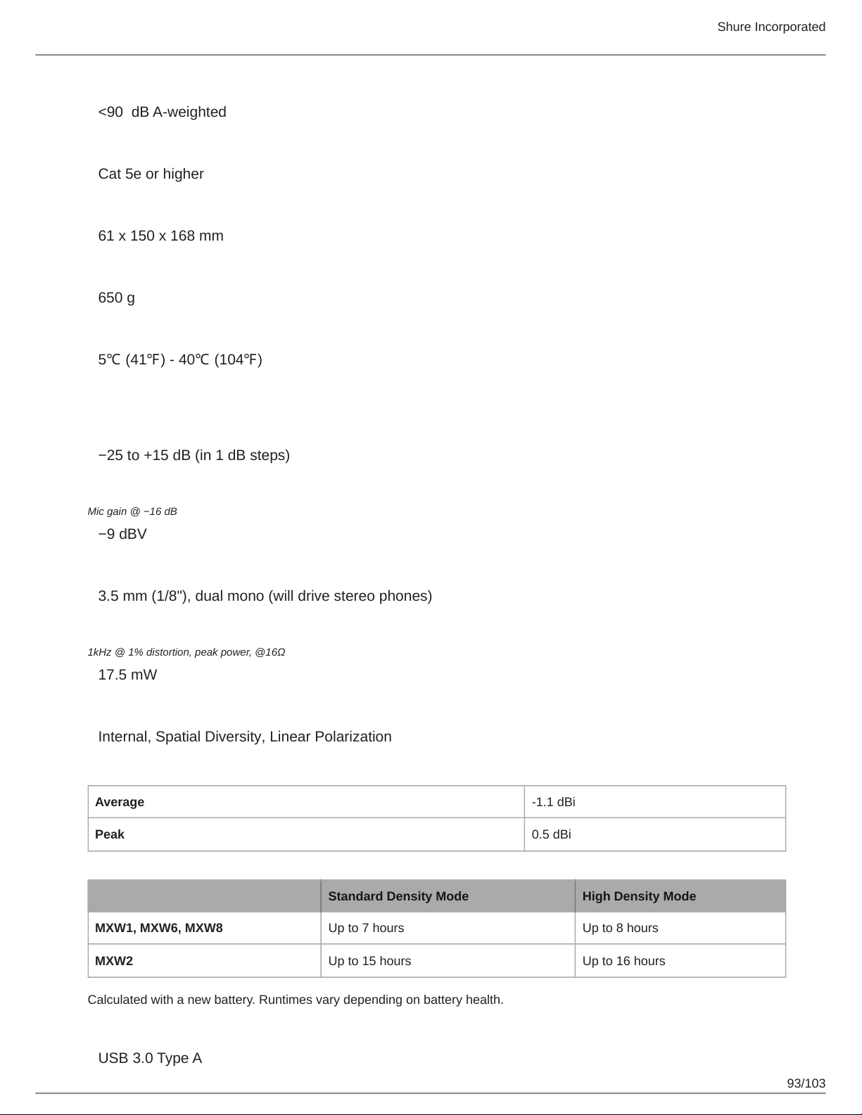
Signal-to-Noise Ratio
<90 dB Aweighted
Cable Requirements
Cat 5e or higher
Dimensions
61 x 150 x 168 mm
Weight
650 g
Operating Temperature Range
5℃ (41℉) - 40℃ (104℉)
Transmitters
Gain Adjustment Range
−25 to +15 dB (in 1 dB steps)
Shure Incorporated
Maximum Input Level
Mic gain @ −16 dB
−9 dBV
Headphone Output
3.5 mm (1/8"), dual mono (will drive stereo phones)
Maximum Headphone Output Power
1kHz @ 1% distortion, peak power, @16Ω
17.5 mW
Antenna Type
Internal, Spatial Diversity, Linear Polarization
Antenna Gain
Average -1.1 dBi
Peak 0.5 dBi
Battery Life
Standard Density Mode High Density Mode
MXW1, MXW6, MXW8 Up to 7 hours Up to 8 hours
MXW2 Up to 15 hours Up to 16 hours
Calculated with a new battery. Runtimes vary depending on battery health.
Charge Connector
USB 3.0 Type A
93/103
Page 94
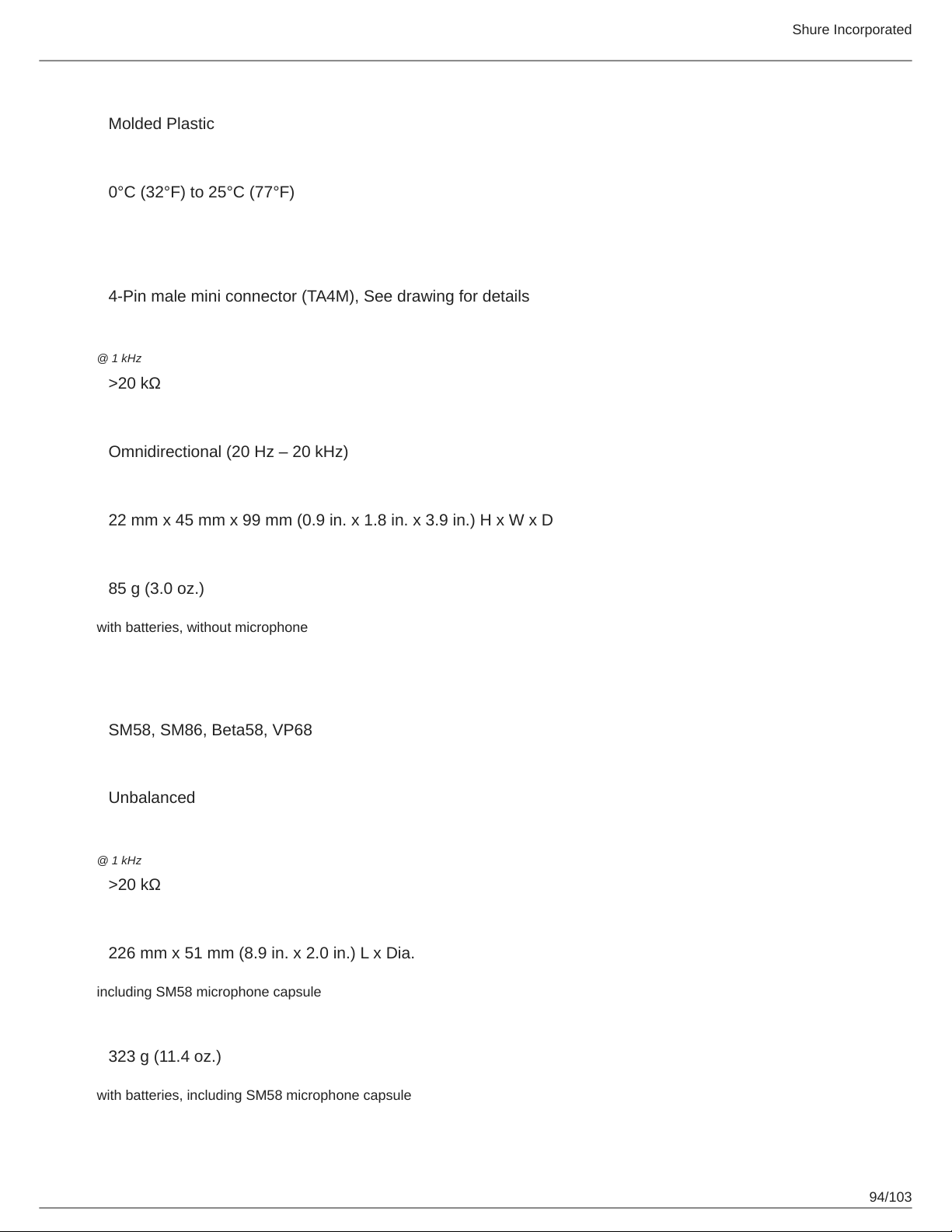
Housing
Molded Plastic
Recommended Storage Temperature Range
0°C (32°F) to 25°C (77°F)
MXW1 Hybrid Bodypack Transmitter
Microphone Connector
4-Pin male mini connector (TA4M), See drawing for details
Input Impedance
@ 1 kHz
>20 kΩ
Internal Microphone
Omnidirectional (20 Hz – 20 kHz)
Shure Incorporated
Dimensions
22 mm x 45 mm x 99 mm (0.9 in. x 1.8 in. x 3.9 in.) H x W x D
Weight
85 g (3.0 oz.)
with batteries, without microphone
MXW2 Handheld Transmitter
Microphone Capsule
SM58, SM86, Beta58, VP68
Configuration
Unbalanced
Input Impedance
@ 1 kHz
>20 kΩ
Dimensions
226 mm x 51 mm (8.9 in. x 2.0 in.) L x Dia.
including SM58 microphone capsule
Weight
323 g (11.4 oz.)
with batteries, including SM58 microphone capsule
94/103
Page 95
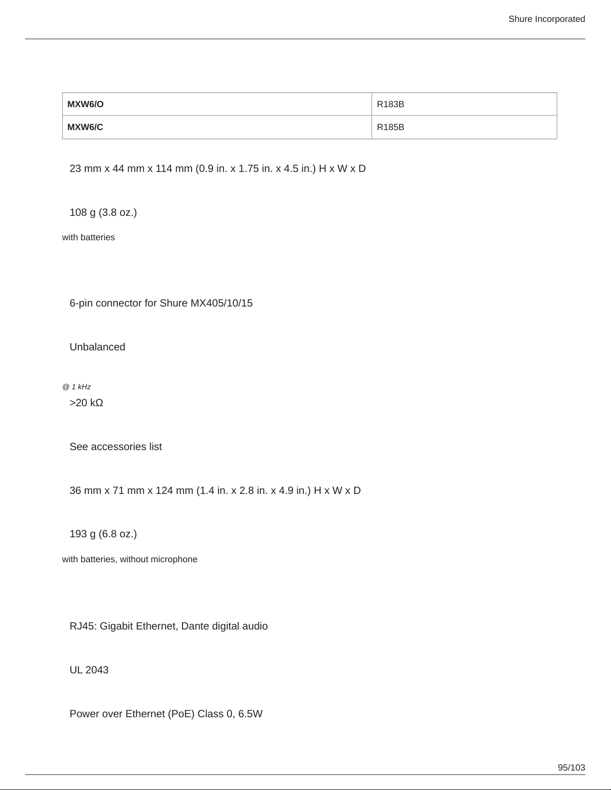
MXW6 Boundary Transmitter
Microphone Capsule
MXW6/O R183B
MXW6/C R185B
Dimensions
23 mm x 44 mm x 114 mm (0.9 in. x 1.75 in. x 4.5 in.) H x W x D
Weight
108 g (3.8 oz.)
with batteries
MXW8 Gooseneck-Base Transmitter
Microphone Connector
6-pin connector for Shure MX405/10/15
Shure Incorporated
Configuration
Unbalanced
Input Impedance
@ 1 kHz
>20 kΩ
Gooseneck Options
See accessories list
Dimensions
36 mm x 71 mm x 124 mm (1.4 in. x 2.8 in. x 4.9 in.) H x W x D
Weight
193 g (6.8 oz.)
with batteries, without microphone
Access Point Transceiver (APT)
Network Interface
RJ45: Gigabit Ethernet, Dante digital audio
Plenum Rating
UL 2043
Power Requirement
Power over Ethernet (PoE) Class 0, 6.5W
95/103
Page 96
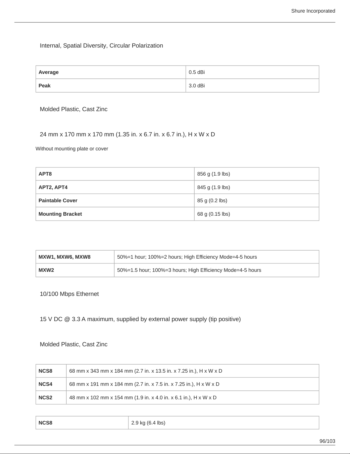
Antenna Type
Internal, Spatial Diversity, Circular Polarization
Antenna Gain
Average 0.5 dBi
Peak 3.0 dBi
Housing
Molded Plastic, Cast Zinc
Dimensions
24 mm x 170 mm x 170 mm (1.35 in. x 6.7 in. x 6.7 in.), H x W x D
Without mounting plate or cover
Weight
APT8 856 g (1.9 lbs)
Shure Incorporated
APT2, APT4 845 g (1.9 lbs)
Paintable Cover 85 g (0.2 lbs)
Mounting Bracket 68 g (0.15 lbs)
Networked Charging Station (NCS)
Charge Time
MXW1, MXW6, MXW8 50%=1 hour; 100%=2 hours; High Efficiency Mode=4-5 hours
MXW2 50%=1.5 hour; 100%=3 hours; High Efficiency Mode=4-5 hours
Network Interface
10/100 Mbps Ethernet
Power Requirement
15 V DC @ 3.3 A maximum, supplied by external power supply (tip positive)
Housing
Molded Plastic, Cast Zinc
Dimensions
NCS8 68 mm x 343 mm x 184 mm (2.7 in. x 13.5 in. x 7.25 in.), H x W x D
NCS4 68 mm x 191 mm x 184 mm (2.7 in. x 7.5 in. x 7.25 in.), H x W x D
NCS2 48 mm x 102 mm x 154 mm (1.9 in. x 4.0 in. x 6.1 in.), H x W x D
Weight
NCS8 2.9 kg (6.4 lbs)
96/103
Page 97
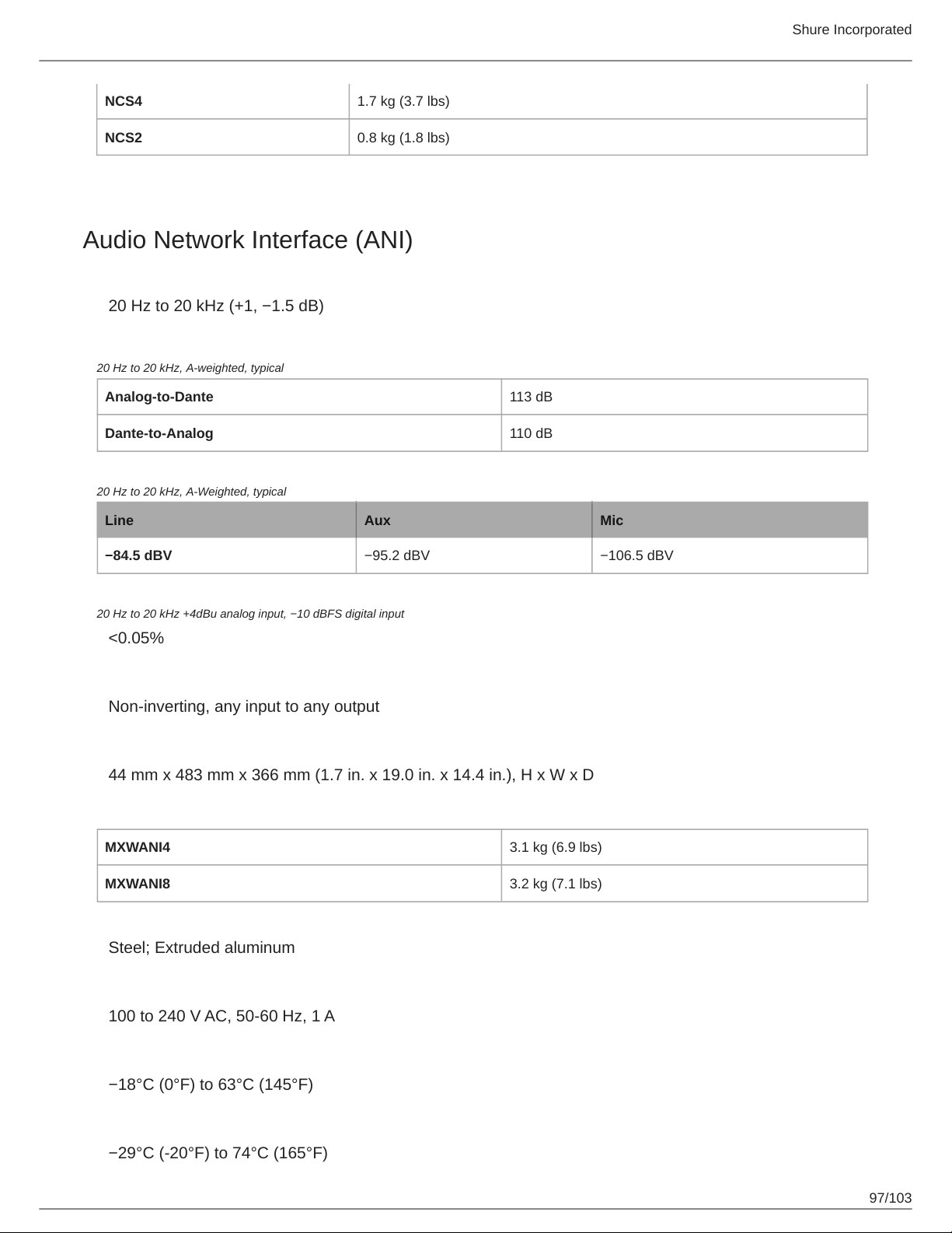
NCS4 1.7 kg (3.7 lbs)
NCS2 0.8 kg (1.8 lbs)
Audio Network Interface (ANI)
Audio Network Interface (ANI)
Audio Frequency Response
20 Hz to 20 kHz (+1, −1.5 dB)
Dynamic Range
20 Hz to 20 kHz, A-weighted, typical
Analog-to-Dante 113 dB
Dante-to-Analog 110 dB
Output Noise
20 Hz to 20 kHz, A-Weighted, typical
Shure Incorporated
Line Aux Mic
−84.5 dBV −95.2 dBV −106.5 dBV
THD+N
20 Hz to 20 kHz +4dBu analog input, −10 dBFS digital input
<0.05%
Polarity
Non-inverting, any input to any output
Dimensions
44 mm x 483 mm x 366 mm (1.7 in. x 19.0 in. x 14.4 in.), H x W x D
Weight
MXWANI4 3.1 kg (6.9 lbs)
MXWANI8 3.2 kg (7.1 lbs)
Housing
Steel; Extruded aluminum
Power Requirements
100 to 240 V AC, 50-60 Hz, 1 A
Operating Temperature Range
−18°C (0°F) to 63°C (145°F)
Storage Temperature Range
−29°C (20°F) to 74°C (165°F)
97/103
Page 98
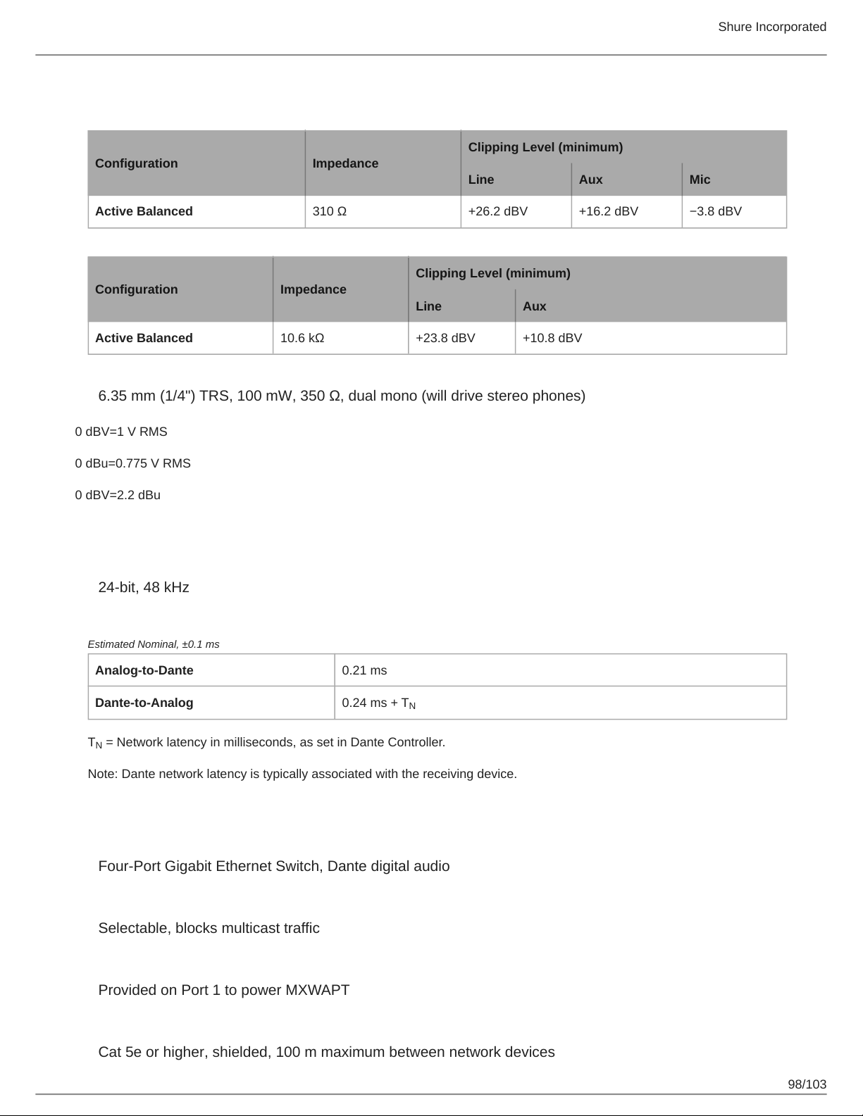
Analog Connections
Outputs
Clipping Level (minimum)
Configuration Impedance
Line Aux Mic
Active Balanced 310 Ω +26.2 dBV +16.2 dBV −3.8 dBV
Input(s)
Clipping Level (minimum)
Configuration Impedance
Line Aux
Active Balanced 10.6 kΩ +23.8 dBV +10.8 dBV
Headphone Output
6.35 mm (1/4") TRS, 100 mW, 350 Ω, dual mono (will drive stereo phones)
0 dBV=1 V RMS
Shure Incorporated
0 dBu=0.775 V RMS
0 dBV=2.2 dBu
Digital Signal Processing
AD/DA Converter
24-bit, 48 kHz
Latency
Estimated Nominal, ±0.1 ms
Analog-to-Dante 0.21 ms
Dante-to-Analog 0.24 ms + T
T = Network latency in milliseconds, as set in Dante Controller.
N
Note: Dante network latency is typically associated with the receiving device.
N
Networking
Network Interface
Four-Port Gigabit Ethernet Switch, Dante digital audio
Uplink Port (Port 4)
Selectable, blocks multicast traffic
Power over Ethernet (PoE)
Provided on Port 1 to power MXWAPT
Cable Requirements
Cat 5e or higher, shielded, 100 m maximum between network devices
98/103
Page 99
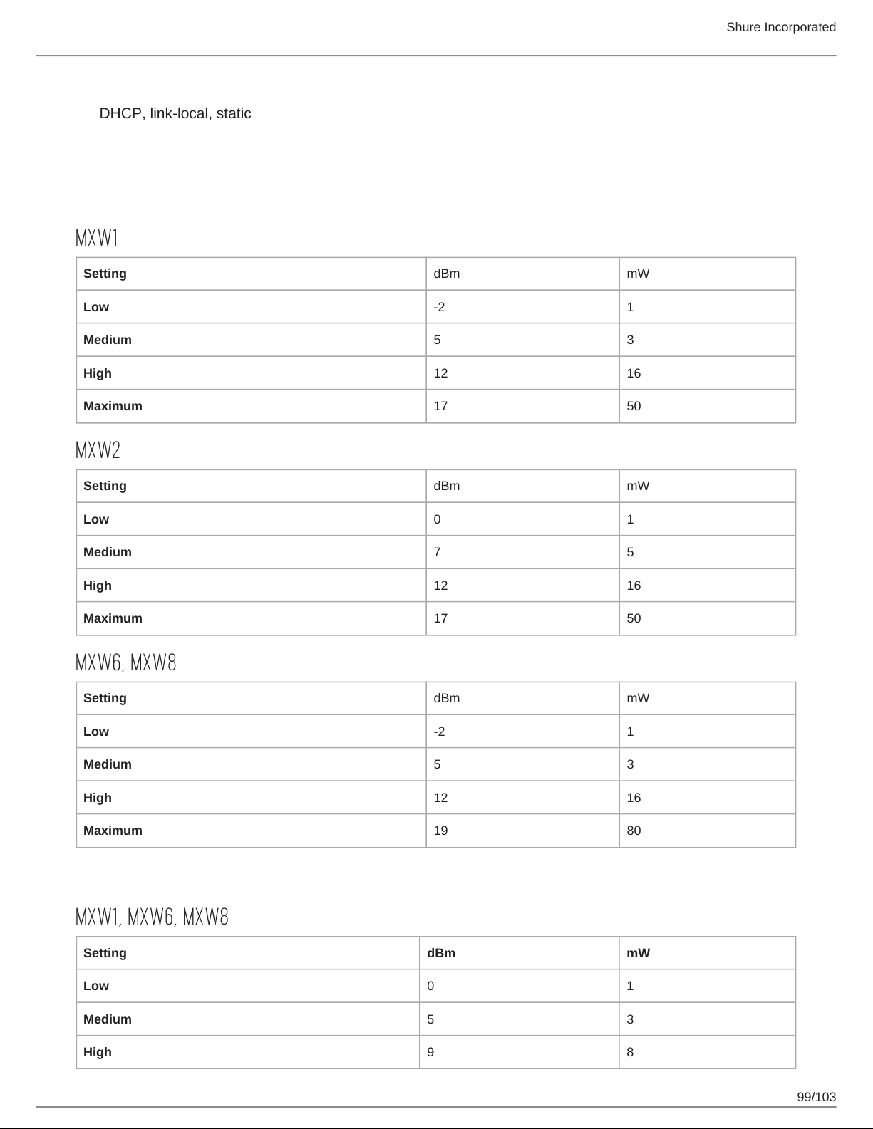
Network Addressing Capability
DHCP, link-local, static
Transmitter Output Power
Bands: Z10, Z11, Z14, Z15
MXW1
Setting dBm mW
Low -2 1
Medium 5 3
High 12 16
Maximum 17 50
Shure Incorporated
MXW2
Setting dBm mW
Low 0 1
Medium 7 5
High 12 16
Maximum 17 50
MXW6, MXW8
Setting dBm mW
Low -2 1
Medium 5 3
High 12 16
Maximum 19 80
Band: Z12
MXW1, MXW6, MXW8
Setting dBm mW
Low 0 1
Medium 5 3
High 9 8
99/103
Page 100
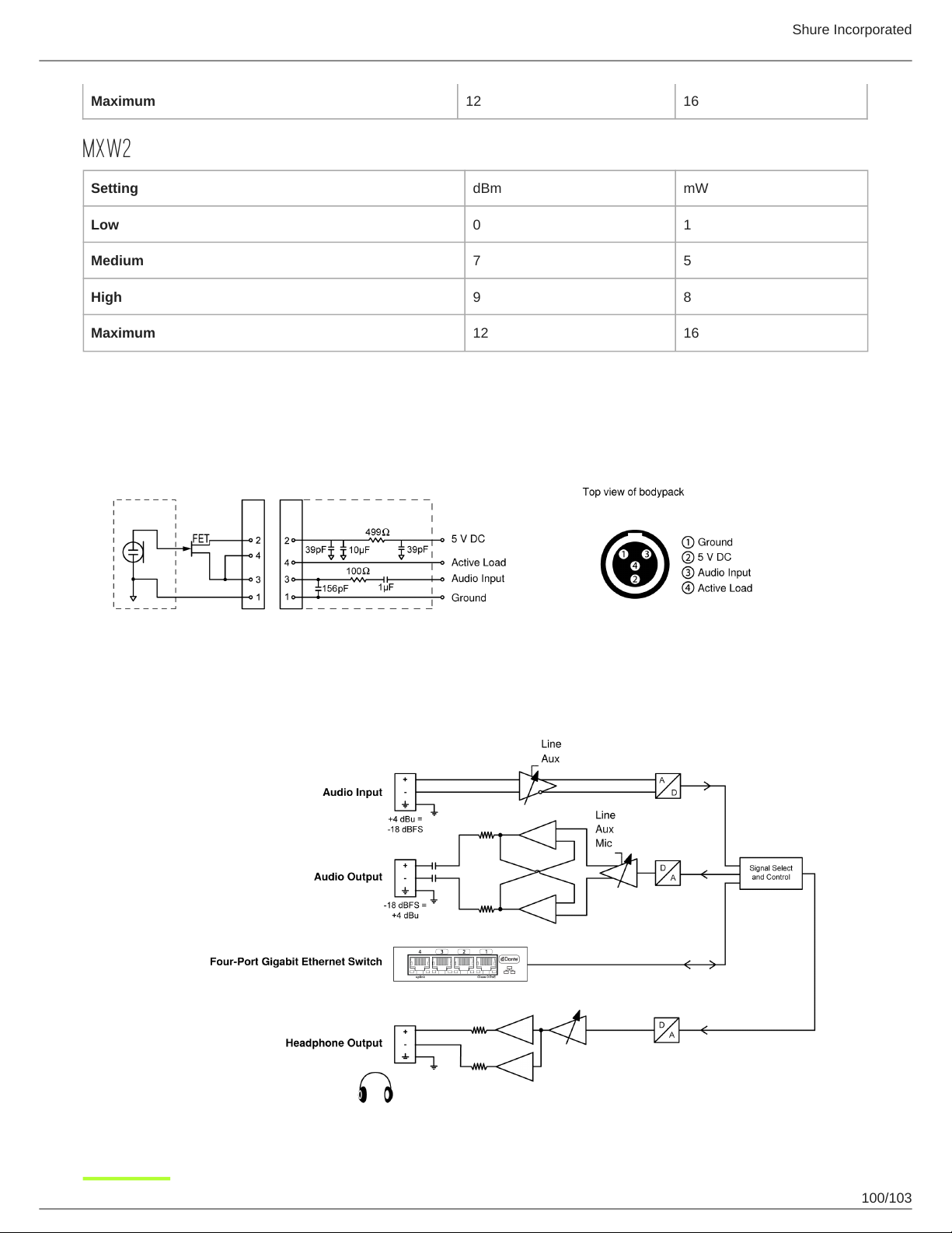
Maximum 12 16
MXW2
Setting dBm mW
Low 0 1
Medium 7 5
High 9 8
Maximum 12 16
Wiring Diagram
TA4M Connector
Shure Incorporated
Audio Network Interface (ANI)
100/103
 Loading...