

Page 1
MXC
®
Microflex Complete
User guide for the Shure Microflex Complete audio conferencing system.
Version: 2 (2019-I)
Page 2

Table of Contents
MXCMicroflex® Complete 4
Important Safeguards 4
Labels 5
Note for Power Connections 5
Power Disconnect 6
Warning: 6
Overview 6
Information in This Manual 6
Features 6
Feature Licenses 7
DIS-CCU Central Control Unit 9
Simplified Audio Diagram 10
CCU Hardware Description 10
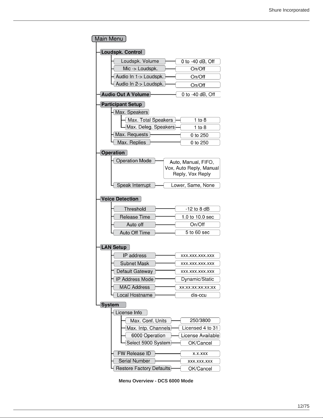
Menu Navigation 11
MXC Conference Units 13
Conference Unit Hardware Descriptions 13
Portable Model Variations 14
Flush-Mounted Model Variations 16
NFC Card functionality 18
Microflex Multipin Gooseneck Microphones 18
Snap-Fit Windscreen 19
Connecting Conference Units and DCS-LAN Compo-
nents 20
Connection Diagrams 21
Basic Setup with Conference Units 21
Controlling the Conference Unit 23
Chairman Role 24
Delegate Role 24
Shure Incorporated
Dual Delegate Role 24
User Indications 25
Web Interface 25
Open the CCU Web Interface 26
Assigning the Network Address 27
Additional Screens 27
Language Setting 30
User Interface for the MXC640 31
Navigation Pane 32
Home Screen 33
Agenda 34
Voting/Result Menu 35
Results 35
Channel Selector 36
Voting Functionality 37
Audio Settings 37
Microphone Functionality 37
Route Microphones to Groups 38
Floor Mix on the Loudspeakers 39
Headphone Channels 39
Analog Audio Outputs 40
Adding an External Audio Source 40
Meeting Configuration 41
Names, Roles and Seat Numbers 42
Meeting Controls 43
Voice Detection 47
Security 48
Password Protect the Browser Interface 49
Language Interpretation 49
Interpretation Setup 50
2/75
Page 3

Shure Incorporated
Interpretation Settings 50
Wireless Language Distribution 51
Listening to Interpretation 52
Firmware Update 52
Rackmounting the CCU 52
Installing the Conference Units 53
Connecting DCS-LAN Equipment 54
Installing Large Systems 57
Troubleshooting 58
Diagnostics 59
Backup, Restore, Factory Reset 61
Devices and Accessories 61
Model Variations 62
PS-CCU Power Supply 63
Optional Accessories and Replacement Parts 63
Technical Specifications 64
Microflex Complete System 64
Wiring Details 64
Common System Specifications 66
Conference Unit Specifications 67
Audio Specifications 72
Cleaning 74
Repacking 74
Warranty 74
Important Product Information 74
Certifications 75
3/75
Page 4
MXC
Microflex Complete
®
Important Safeguards
1.
Read these instructions - All the safety and operating instructions should be read before the apparatus or system is
operated.
2.
Keep these instructions - The important safety instructions and operating instructions should be retained for future
reference.
3.
Follow all warnings - All warnings on the apparatus and in the operating instructions should be adhered to.
4.
Follow all instructions - All instructions for installation or use/operating should be followed.
5.
Do not use this apparatus near water - Do not use this apparatus in a water or moistures environment - for example,
near a bath tub, wash bowl, kitchen sink, or laundry tub, in a wet basement, near a swimming pool, in an unprotected
outdoor installation, or any area which is classified as a wet location.
6.
Warning: To reduce the risk of fire or electric shock, do not expose this apparatus to rain or moisture and no
objects filled with liquids, such as vases, should be placed on this apparatus.
7.
Clean only with dry cloth - Unplug the apparatus from the outlet before cleaning. Do not use liquid cleaners or aerosol
cleaners.
8.
Do not block any ventilation openings. Install in accordance with the manufacturer’s instructions - Openings in
the enclosure, if any, are provided for ventilation and to ensure reliable operation of the apparatus and to protect it from
overheating. These openings must not be blocked or covered. This apparatus should not be placed in a built-in installa-
tion unless proper ventilation is provided or the manufacturer’s instructions have been adhered to.
9.
Do not install near any heat sources such as radiators, heat registers, stoves, air ducts, or other apparatus (in-
cluding amplifiers) that produce heat.
10.
Do not install the unit in a place exposed to direct sunlight, excessive dust or humidity, mechanical vibration or
shock .
11.
To avoid moisture condensations do not install the unit where the temperature may rise rapidly.
12.
Do not defeat the safety purpose of the polarized or ground-type plug. A polarized plug has two blades with one
wider than the other. A grounding type plug has two blades and a third grounding prong. The wider blade or the third
prong is provided for your safety. If the provided plug does not fit into your outlet, consult an electrician for replacement
of the obsolete outlet.
13.
Protect the power cord from being walked on or pinched particularly at plug, convenience receptacles, and the
point where they exit from the apparatus.
14.
Only use attachments/accessories specified by the manufacturer . Any mounting of the apparatus should follow
the manufacturer’s instructions, and should use a mounting accessory recommended by the manufacturer.
15.
Use only with the cart, stand, tripod, bracket or table specified by the manufacturer, or sold with the apparatus.
Shure Incorporated
When a cart is used, use caution when moving the cart/apparatus combination to avoid in-
jury from tip-over - Quick stops, excessive force, and uneven surfaces may cause the appli-
ance and cart combination to overturn.
16.
Unplug this apparatus during lighting storms or when unused for long periods of time . – Not applicable when
special functions are to be maintained, such as evacuation systems.
4/75
Page 5
Shure Incorporated
17.
Refer all servicing to qualified service personnel. Servicing is required when the apparatus has been damaged
in any way, such as power-supply cord or plug is damaged, liquid has been spilled or objects have fallen into
the apparatus, the apparatus has been exposed to rain or moisture, does not operate normally, or has been
dropped.
18.
Replacement Parts - When replacement parts are required, be sure the service technician has used replacement parts
specified by the manufacturer or having the same characteristics as the original part.
Unauthorized substitutions may result in fire, electric shock or other hazards.
19.
Safety Check - Upon completion of any service or repairs to this apparatus, ask the service technician to perform safe-
ty checks to determine that the apparatus is in proper operating condition.
20.
Overloading - Do not overload outlets and extension cords as this can result in a risk of fire or electric shock.
21.
Power Sources - This apparatus should be operated only from the type of power source indicated on the marking la-
bel. If you are not sure of the type of power supply you plan to use, consult your appliance dealer or local power com-
pany. For apparatuses intended to operate from battery power, or other sources, refer to the operating instructions.
22.
Power Lines - An outdoor system should not be located in the vicinity of overhead power lines or other electric light or
power circuits, or where it can fall into such power lines or circuits. When installing an outdoor system, extreme care
should be taken to keep from touching such power lines or circuits, as contact with them might be fatal.
23.
Object and Liquid Entry - Never push objects of any kind into this apparatus through openings as they may touch
dangerous voltage points or short-out parts that could result in a fire or electric shock.
Never spill liquid of any kind on the apparatus. Should any liquid or solid object fall into the cabinet, unplug the unit and
have it checked by qualified personnel before operating it further.
Labels
“Lightning Flash Symbol” with the lightning flash with arrowhead symbol within an equilateral triangle, is
intended to alert the user to the presence of un-insulated "dangerous voltage" within the product enclo-
sure that may be of sufficient magnitude to constitute a risk of shock to persons.
“Exclamation Point Symbol” with the exclamation point within an equilateral triangle is intended to alert
the user to the presence of important operating and maintenance (servicing) instructions in the literature
accompanying the product.
Note for Power Connections
Check that the voltage of your local power supply is within the operating voltage of the unit. If a voltage conversion is required,
consult your DIS dealer or qualified personnel.
Set the Power switch to ‘Off’ if it is not used for several days.
Important: The equipment must be connected to earth (ground)
The wires in the main lead supplied with the equipment are colored in accordance with the following codes:
•
Green-and-yellow Earth (Ground)
•
Blue Neutral
•
Brown Live
•
The green-and-yellow wire must be connected to the terminal in the plug marked with the letter E or with the safety earth
symbol or marked with green-and-yellow color.
•
The blue wire must be connected to the terminal marked with the letter N or marked with black color.
•
The brown wire must be connected to the terminal marked with the letter L or marked with red color.
•
For pluggable equipment, the socket-outlet shall be installed near the equipment and shall be easily accessible.
5/75
Page 6
Shure Incorporated
Power Disconnect
Apparatuses with or without On/Off switches have power supplied to the apparatus whenever the power cord is inserted into
the power source; however, the apparatus is operational only when the On/Off switch is in the On position. The power cord is
the main power disconnect for all apparatuses.
Warning:
Operation is subject to the following conditions: (1) The device may not cause harmful interference, and (2) the device must ac-
cept any interference received, including interference that may cause undesired operation.
These limits are designed to provide reasonable protection against harmful interference when the equipment is operated in
residential, commercial or light industrial environments. The equipment generates, uses, and can radiate radio frequency ener-
gy and if not installed and used in accordance with the user manual it may cause harmful interference to radio communica-
tions.
Operation of this equipment in residential areas is likely to cause harmful interference in which case the user will be required to
correct the interference at his or her own expense. Intentional or unintentional changes or modifications not expressly ap-
proved by the party responsible for compliance shall not be made. Any such changes or modifications could void the user’s au-
thority to operate the equipment.
If necessary, the user should consult a dealer or an experienced radio/ television technician for corrective action. The user may
find the following booklet prepared by the Federal Communications Commission helpful: "How to identify and Resolve Radio-
TV Interference Problems". This booklet is available from the U.S. Government Printing Office, Washington, DC 20402, Stock
No. 004-000-00345-4.
Warning: This is a Class A product. In a domestic environment this product may cause radio interference in which case the
user may be required to take adequate measures.
Overview
The Shure Microflex Complete (MXC) Digital Conference System is designed for meetings featuring multiple speakers and ac-
tive meeting participants. A single system supports MXC and legacy DCS conference units, dedicated interpretation consoles,
and integration with SW6000 meeting management software.
Microflex Complete complies with international conference standards, supporting advanced speaker control, simultaneous in-
terpretation, voting functionality, and conference management for up to 3,800 participants.
®
Information in This Manual
The CCU operates standard in "5900" mode for use in a DDS 5900 system. By uploading a feature license, the CCU can oper-
ate in "6000" mode for use in MXC and legacy DCS 6000 systems. This manual describes the CCU when operating in 6000
mode.
For information on operation with the DDS 5900 Discussion system, consult that manual found on the Shure website.
Features
When set to 6000 mode, the CCU has the following features:
•
Controls a system of conference units, interpreter consoles, and channel selectors
6/75
Page 7
Shure Incorporated
•
Transports secure audio signal with a proprietary codec algorithm
•
Provides a web server for advanced control through a browser interface
•
Supplies power to the units in the system
•
Supports up to 31 interpretation channels for multilingual meetings
•
Provides eight audio outputs to send interpretation channels or microphone groups to PA systems, audio mixers, audio
recorders, or a language distribution system
•
Provides two audio inputs for connecting wireless microphones, processed audio signals, an emergency broadcast mes-
sage (EEM), or music during meeting breaks
•
One rack unit (1RU) size installs into a standard 19" rack
Feature Licenses
The CCU operates with DDS 5900, legacy DCS 6000, and MXC conference systems. The CCU includes the DDS 5900 mode
as standard, and can operate in 6000 mode after installing a feature license.
To use MXC or DCS 6000 conference units, ensure the FL6000 is installed and operating on the CCU.
Purchasing the Feature License File
Contact your regional Shure sales representative to purchase a feature license file to enable 6000 mode and expansion fea-
tures. The features are bundled in a single .xml file generated specifically for the serial number of the CCU.
Adding the License to the CCU
After purchasing the license file, upload it to the unit using the CCU web interface:
1.
Save the license file (.xml extension) to the computer or USB drive.
2.
Connect the CCU and open the web interface. Sign in as the Admin if a password has been set.
3.
Go to the License page (System > License).
Note: Before the license is loaded to the system, only the DDS 5900 mode is available
4.
Select Browse to locate the license file.
5.
Select Go to install the file to the CCU. The unit will reboot.
7/75
Page 8
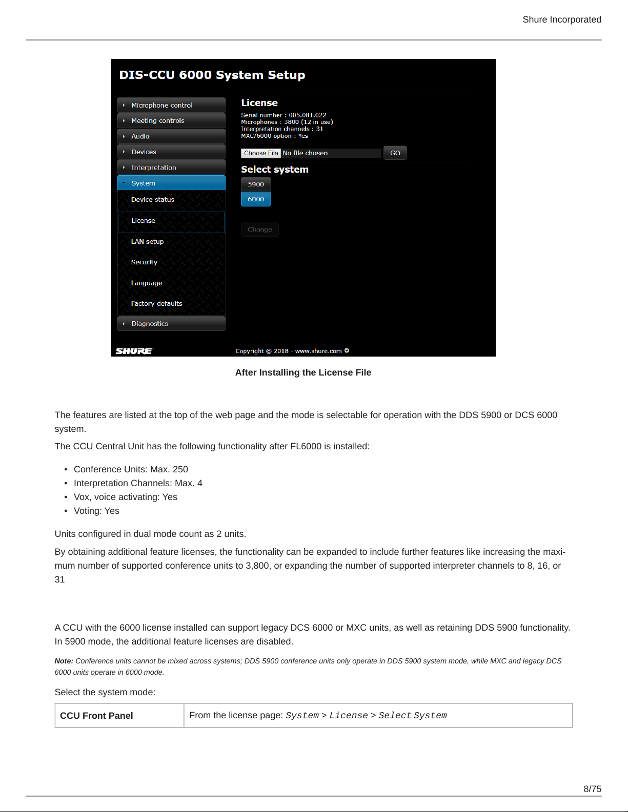
Shure Incorporated
After Installing the License File
The features are listed at the top of the web page and the mode is selectable for operation with the DDS 5900 or DCS 6000
system.
The CCU Central Unit has the following functionality after FL6000 is installed:
•
Conference Units: Max. 250
•
Interpretation Channels: Max. 4
•
Vox, voice activating: Yes
•
Voting: Yes
Units configured in dual mode count as 2 units.
By obtaining additional feature licenses, the functionality can be expanded to include further features like increasing the maxi-
mum number of supported conference units to 3,800, or expanding the number of supported interpreter channels to 8, 16, or
31
Select the System Mode
A CCU with the 6000 license installed can support legacy DCS 6000 or MXC units, as well as retaining DDS 5900 functionality.
In 5900 mode, the additional feature licenses are disabled.
Note: Conference units cannot be mixed across systems; DDS 5900 conference units only operate in DDS 5900 system mode, while MXC and legacy DCS
6000 units operate in 6000 mode.
Select the system mode:
CCU Front Panel
From the license page: System > License > Select System
8/75
Page 9
Shure Incorporated
Web Interface
System > License Info > Select [5900 or 6000] System
DIS-CCU Central Control Unit
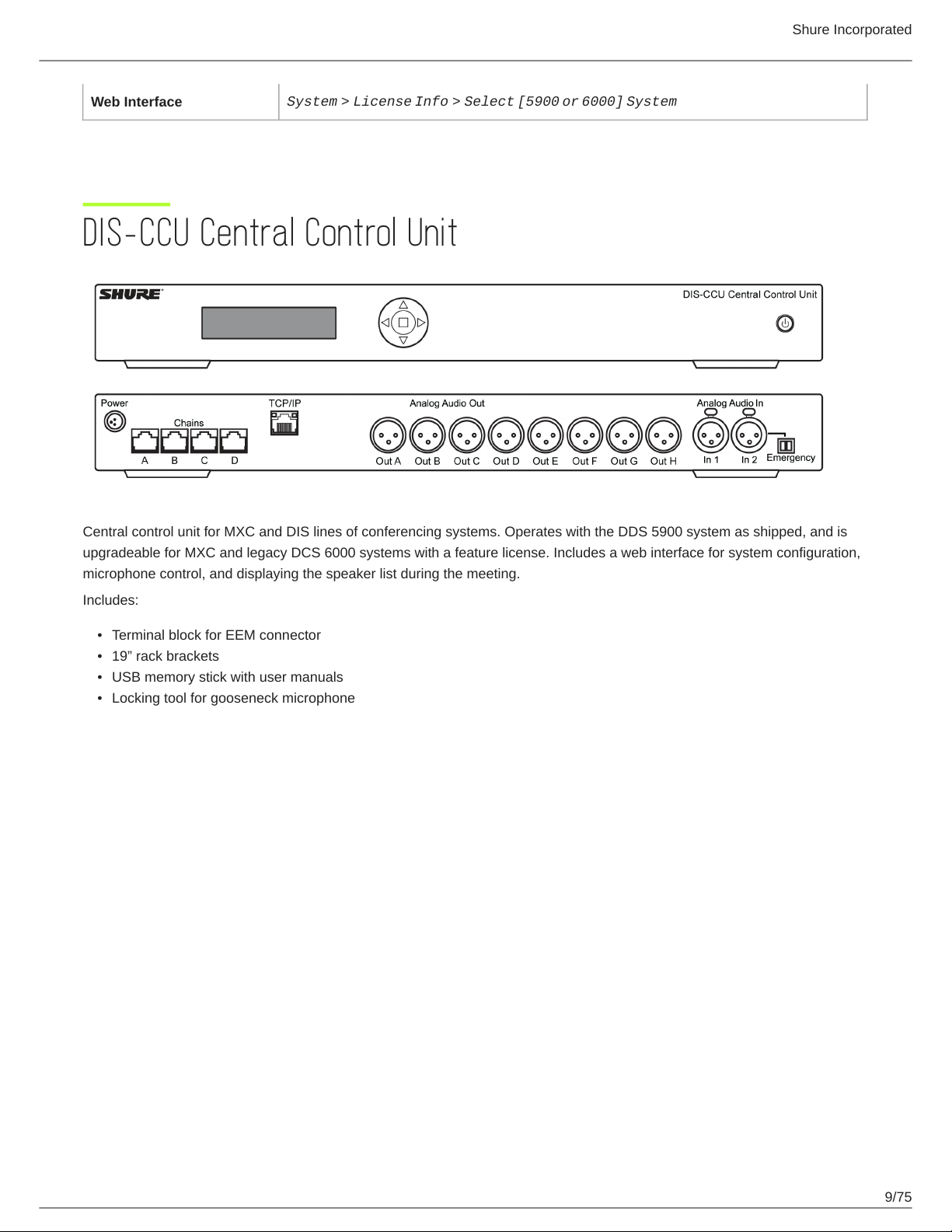
Central control unit for MXC and DIS lines of conferencing systems. Operates with the DDS 5900 system as shipped, and is
upgradeable for MXC and legacy DCS 6000 systems with a feature license. Includes a web interface for system configuration,
microphone control, and displaying the speaker list during the meeting.
Includes:
•
Terminal block for EEM connector
•
19” rack brackets
•
USB memory stick with user manuals
•
Locking tool for gooseneck microphone
9/75
Page 10

Simplified Audio Diagram
Shure Incorporated
CCU Hardware Description
10/75
Page 11
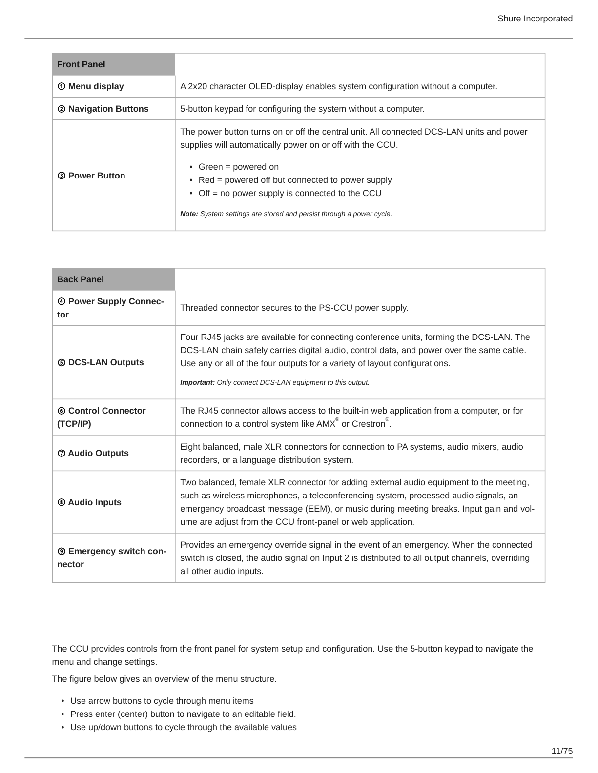
Front Panel
① Menu display A 2x20 character OLED-display enables system configuration without a computer.
② Navigation Buttons 5-button keypad for configuring the system without a computer.
The power button turns on or off the central unit. All connected DCS-LAN units and power
supplies will automatically power on or off with the CCU.
•
③ Power Button
Back Panel
Green = powered on
•
Red = powered off but connected to power supply
•
Off = no power supply is connected to the CCU
Note: System settings are stored and persist through a power cycle.
Shure Incorporated
④ Power Supply Connec-
tor
⑤ DCS-LAN Outputs
⑥ Control Connector
(TCP/IP)
⑦ Audio Outputs
⑧ Audio Inputs
⑨ Emergency switch con-
nector
Threaded connector secures to the PS-CCU power supply.
Four RJ45 jacks are available for connecting conference units, forming the DCS-LAN. The
DCS-LAN chain safely carries digital audio, control data, and power over the same cable.
Use any or all of the four outputs for a variety of layout configurations.
Important: Only connect DCS-LAN equipment to this output.
The RJ45 connector allows access to the built-in web application from a computer, or for
connection to a control system like AMX or Crestron .
Eight balanced, male XLR connectors for connection to PA systems, audio mixers, audio
recorders, or a language distribution system.
Two balanced, female XLR connector for adding external audio equipment to the meeting,
such as wireless microphones, a teleconferencing system, processed audio signals, an
emergency broadcast message (EEM), or music during meeting breaks. Input gain and vol-
ume are adjust from the CCU front-panel or web application.
Provides an emergency override signal in the event of an emergency. When the connected
switch is closed, the audio signal on Input 2 is distributed to all output channels, overriding
all other audio inputs.
® ®
Menu Navigation
The CCU provides controls from the front panel for system setup and configuration. Use the 5-button keypad to navigate the
menu and change settings.
The figure below gives an overview of the menu structure.
•
Use arrow buttons to cycle through menu items
•
Press enter (center) button to navigate to an editable field.
•
Use up/down buttons to cycle through the available values
11/75
Page 12
Shure Incorporated
Menu Overview - DCS 6000 Mode
12/75
Page 13
Shure Incorporated
MXC Conference Units
MXC conference units facilitate communication between participants in group meetings and conferences. The units enable par-
ticipants to speak and be heard with clarity, even in large and multilingual events, by combining a gooseneck microphone, loud-
speaker, headphone jack, and user controls. For advanced meeting tasks, some conference units include features for voting,
following along to the agenda, managing speakers, and more.
Note: Speaker and meeting management settings are highly configurable and can be tailored to meet your event requirements. See meeting setup for more
information.
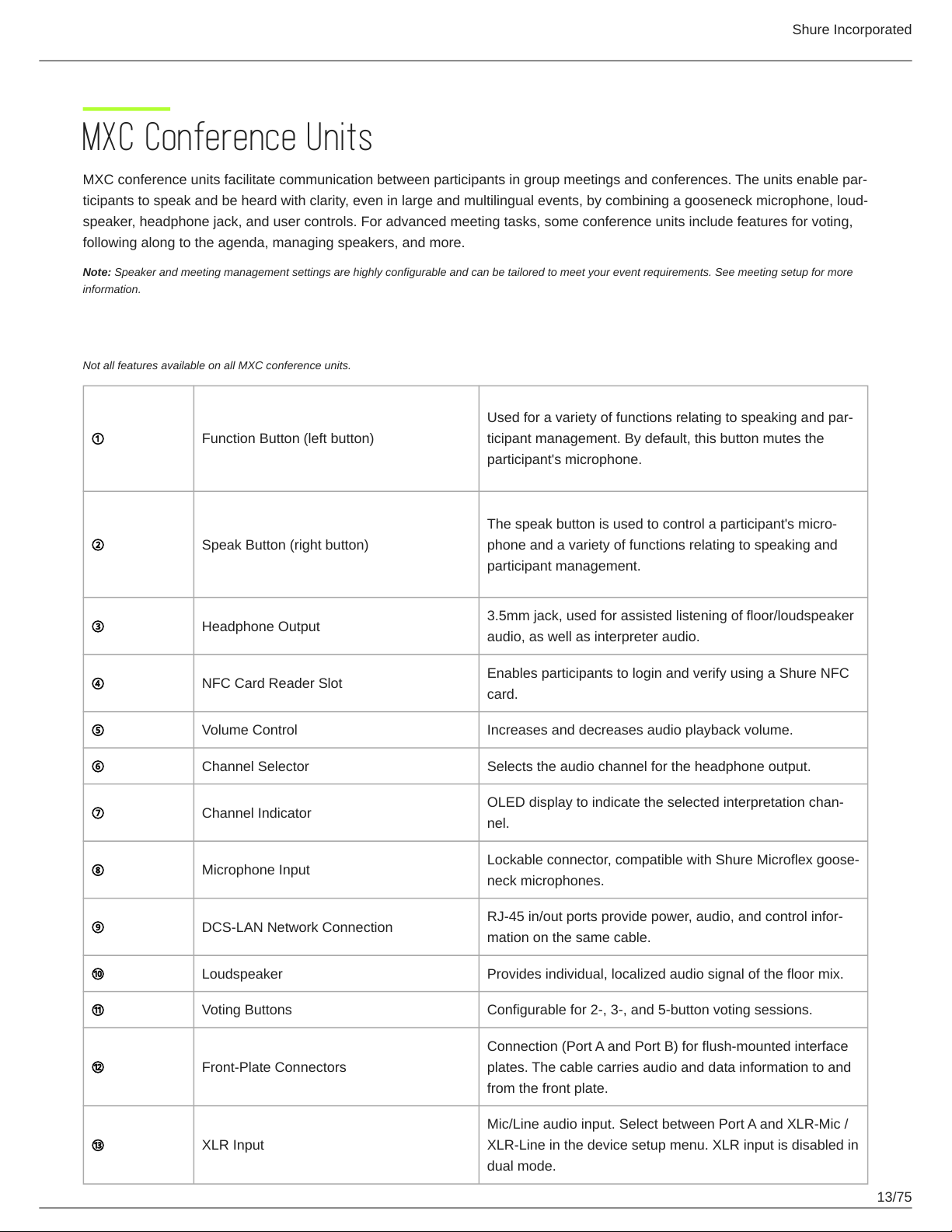
Conference Unit Hardware Descriptions
Not all features available on all MXC conference units.
Used for a variety of functions relating to speaking and par-
① Function Button (left button)
ticipant management. By default, this button mutes the
participant's microphone.
The speak button is used to control a participant's micro-
② Speak Button (right button)
③ Headphone Output
④ NFC Card Reader Slot
⑤ Volume Control Increases and decreases audio playback volume.
⑥ Channel Selector Selects the audio channel for the headphone output.
⑦ Channel Indicator
⑧ Microphone Input
⑨ DCS-LAN Network Connection
⑩ Loudspeaker Provides individual, localized audio signal of the floor mix.
phone and a variety of functions relating to speaking and
participant management.
3.5mm jack, used for assisted listening of floor/loudspeaker
audio, as well as interpreter audio.
Enables participants to login and verify using a Shure NFC
card.
OLED display to indicate the selected interpretation chan-
nel.
Lockable connector, compatible with Shure Microflex goose-
neck microphones.
RJ-45 in/out ports provide power, audio, and control infor-
mation on the same cable.
⑪ Voting Buttons Configurable for 2-, 3-, and 5-button voting sessions.
Connection (Port A and Port B) for flush-mounted interface
⑫ Front-Plate Connectors
⑬ XLR Input
plates. The cable carries audio and data information to and
from the front plate.
Mic/Line audio input. Select between Port A and XLR-Mic /
XLR-Line in the device setup menu. XLR input is disabled in
dual mode.
13/75
Page 14

Shure Incorporated
⑭ Ground/Lift Toggle Lifts the ground from pin 1 of the XLR input.
⑮ Touch Screen Provides voting and advanced meeting interaction.
Portable Model Variations
MXC615 & MXC620 Conference Unit
Features participant identification using NFC card (MXC620 only), dual-language channel selector and an optional Braille
'Mute/Speak' overlay. Supports chairman, delegate and dual delegate roles.
Note: NFC is not supported with dual-delegate roles.
MXC630 Voting Conference Unit
Conference unit with voting capability, participant identification using NFC card, single-language channel selector, and integrat-
ed Braille 'Mute/Speak' labels for speak and function buttons. Supports chairman and delegate roles.
14/75
Page 15
Shure Incorporated
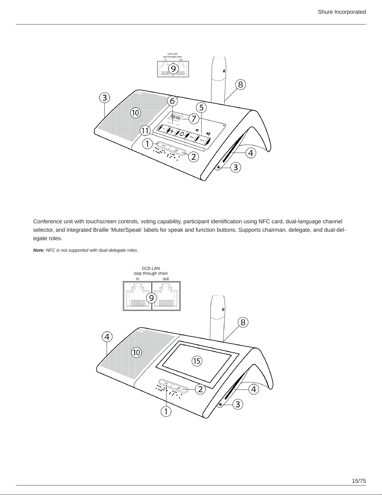
MXC640 Touchscreen Conference Unit
Conference unit with touchscreen controls, voting capability, participant identification using NFC card, dual-language channel
selector, and integrated Braille 'Mute/Speak' labels for speak and function buttons. Supports chairman, delegate, and dual-del-
egate roles.
Note: NFC is not supported with dual-delegate roles.
15/75
Page 16
Shure Incorporated
Flush-Mounted Model Variations
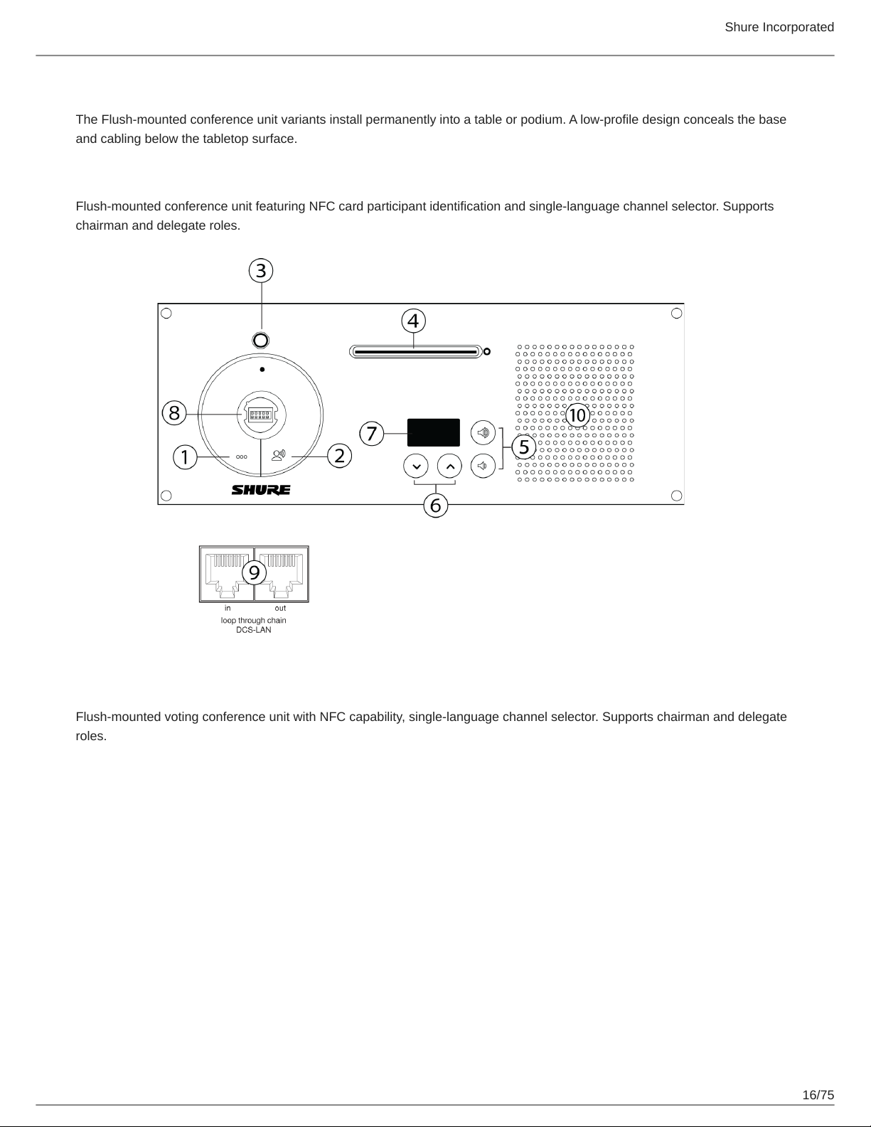
The Flush-mounted conference unit variants install permanently into a table or podium. A low-profile design conceals the base
and cabling below the tabletop surface.
MXC620-F Conference Unit
Flush-mounted conference unit featuring NFC card participant identification and single-language channel selector. Supports
chairman and delegate roles.
MXC630-F Voting Unit
Flush-mounted voting conference unit with NFC capability, single-language channel selector. Supports chairman and delegate
roles.
16/75
Page 17
Shure Incorporated
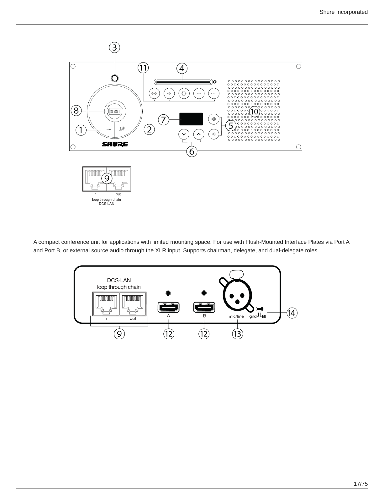
MXCMIU Multi Interface Unit
A compact conference unit for applications with limited mounting space. For use with Flush-Mounted Interface Plates via Port A
and Port B, or external source audio through the XLR input. Supports chairman, delegate, and dual-delegate roles.
17/75
Page 18
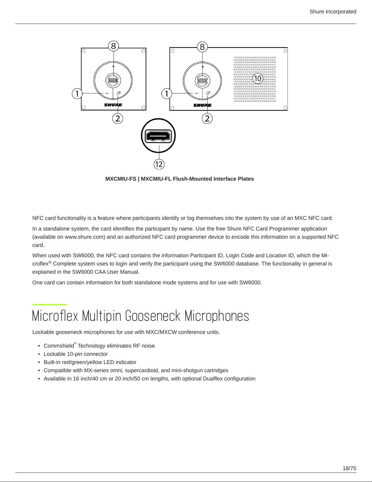
MXCMIU-FS | MXCMIU-FL Flush-Mounted Interface Plates
Shure Incorporated
NFC Card functionality
NFC card functionality is a feature where participants identify or log themselves into the system by use of an MXC NFC card.
In a standalone system, the card identifies the participant by name. Use the free Shure NFC Card Programmer application
(available on www.shure.com) and an authorized NFC card programmer device to encode this information on a supported NFC
card.
When used with SW6000, the NFC card contains the information Participant ID, Login Code and Location ID, which the Mi-
®
croflex Complete system uses to login and verify the participant using the SW6000 database. The functionality in general is
explained in the SW6000 CAA User Manual.
One card can contain information for both standalone mode systems and for use with SW6000.
Microflex Multipin Gooseneck Microphones
Lockable gooseneck microphones for use with MXC/MXCW conference units.
•
Commshield Technology eliminates RF noise
•
Lockable 10-pin connector
•
Built-in red/green/yellow LED indicator
•
Compatible with MX-series omni, supercardioid, and mini-shotgun cartridges
•
Available in 16 inch/40 cm or 20 inch/50 cm lengths, with optional Dualflex configuration
®
18/75
Page 19
Shure Incorporated
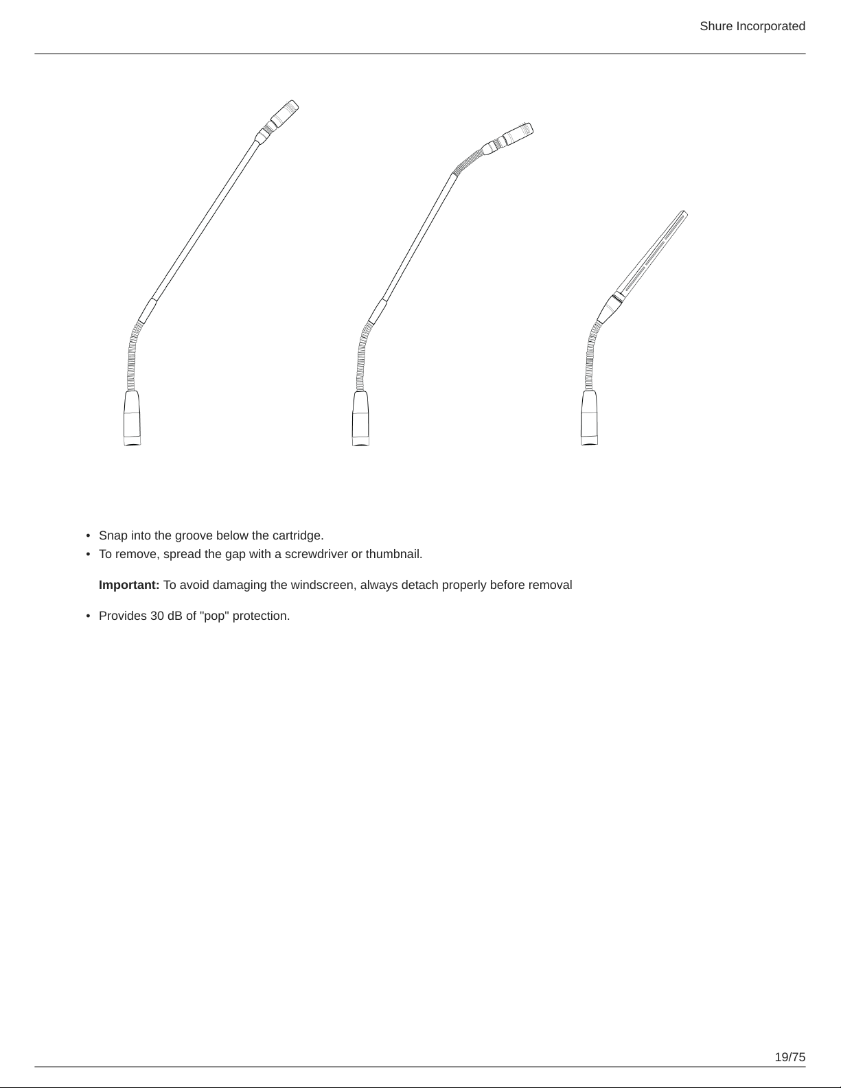
Snap-Fit Windscreen
•
Snap into the groove below the cartridge.
•
To remove, spread the gap with a screwdriver or thumbnail.
Important: To avoid damaging the windscreen, always detach properly before removal
•
Provides 30 dB of "pop" protection.
19/75
Page 20

Shure Incorporated
Connecting Conference Units and DCS-LAN Components
Conference units and DCS-LAN components are connected in sequence (daisy-chain) using the two RJ45 ports on each unit.
Connectors are not interchangeable: the previous unit must be connected to the IN port, and the following unit to the OUT port.
Power, control data, and audio are transported from one unit to the next over the same shielded Cat5e cable.
To protect the equipment, ensure that the central control unit (CCU) is always off when connecting or disconnecting the con-
ference units. Use any of the four chain connectors (A, B, C, and/or D) for connecting DCS-LAN components.
1.
Power off the CCU to protect the equipment during set up.
2.
Connect a chain output on the CCU to the first conference unit with the shielded Cat5e cable.
3.
Connect the rest of the conference units in sequence, using the RJ45 jacks on the bottom of each unit.
20/75
Page 21
Shure Incorporated
4.5.Use the included cable clamp to secure the cables in place.
Turn on the CCU by pressing the power button. The conference units will power on. The unit is stable once the control
button LEDs stop flashing.
Warning: Do not turn off CCU power until the system has stabilized
Connection Diagrams
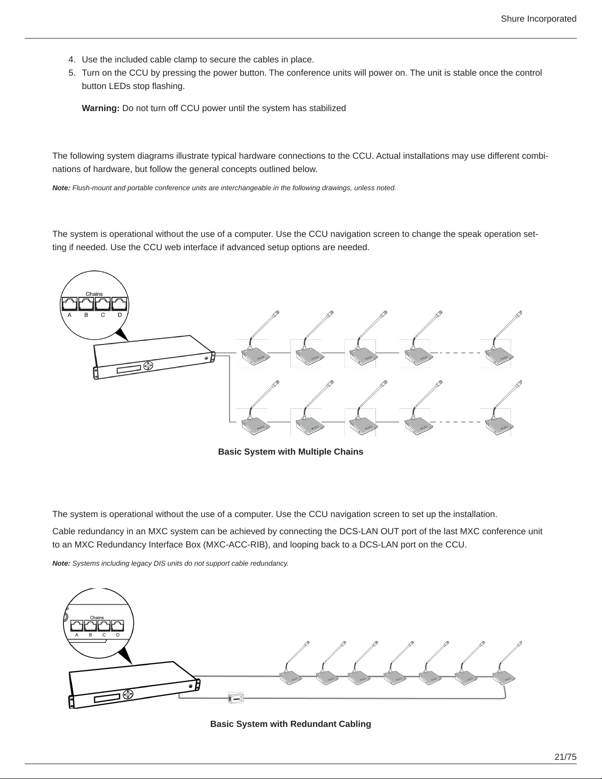
The following system diagrams illustrate typical hardware connections to the CCU. Actual installations may use different combi-
nations of hardware, but follow the general concepts outlined below.
Note: Flush-mount and portable conference units are interchangeable in the following drawings, unless noted.
Basic Setup with Conference Units
The system is operational without the use of a computer. Use the CCU navigation screen to change the speak operation set-
ting if needed. Use the CCU web interface if advanced setup options are needed.
Basic System with Multiple Chains
Redundancy
The system is operational without the use of a computer. Use the CCU navigation screen to set up the installation.
Cable redundancy in an MXC system can be achieved by connecting the DCS-LAN OUT port of the last MXC conference unit
to an MXC Redundancy Interface Box (MXC-ACC-RIB), and looping back to a DCS-LAN port on the CCU.
Note: Systems including legacy DIS units do not support cable redundancy.
Basic System with Redundant Cabling
21/75
Page 22
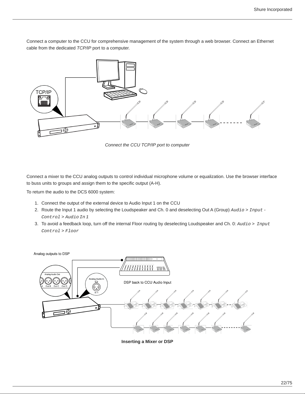
Shure Incorporated
Computer for Advanced Control
Connect a computer to the CCU for comprehensive management of the system through a web browser. Connect an Ethernet
cable from the dedicated TCP/IP port to a computer.
Connect the CCU TCP/IP port to computer
Mixer or DSP
Connect a mixer to the CCU analog outputs to control individual microphone volume or equalization. Use the browser interface
to buss units to groups and assign them to the specific output (A-H).
To return the audio to the DCS 6000 system:
1.
Connect the output of the external device to Audio Input 1 on the CCU
2.
Route the Input 1 audio by selecting the Loudspeaker and Ch. 0 and deselecting Out A (Group) Audio > Input
Control > Audio In 1
3.
To avoid a feedback loop, turn off the internal Floor routing by deselecting Loudspeaker and Ch. 0: Audio > Input
Control > Floor
Inserting a Mixer or DSP
22/75
Page 23
Shure Incorporated
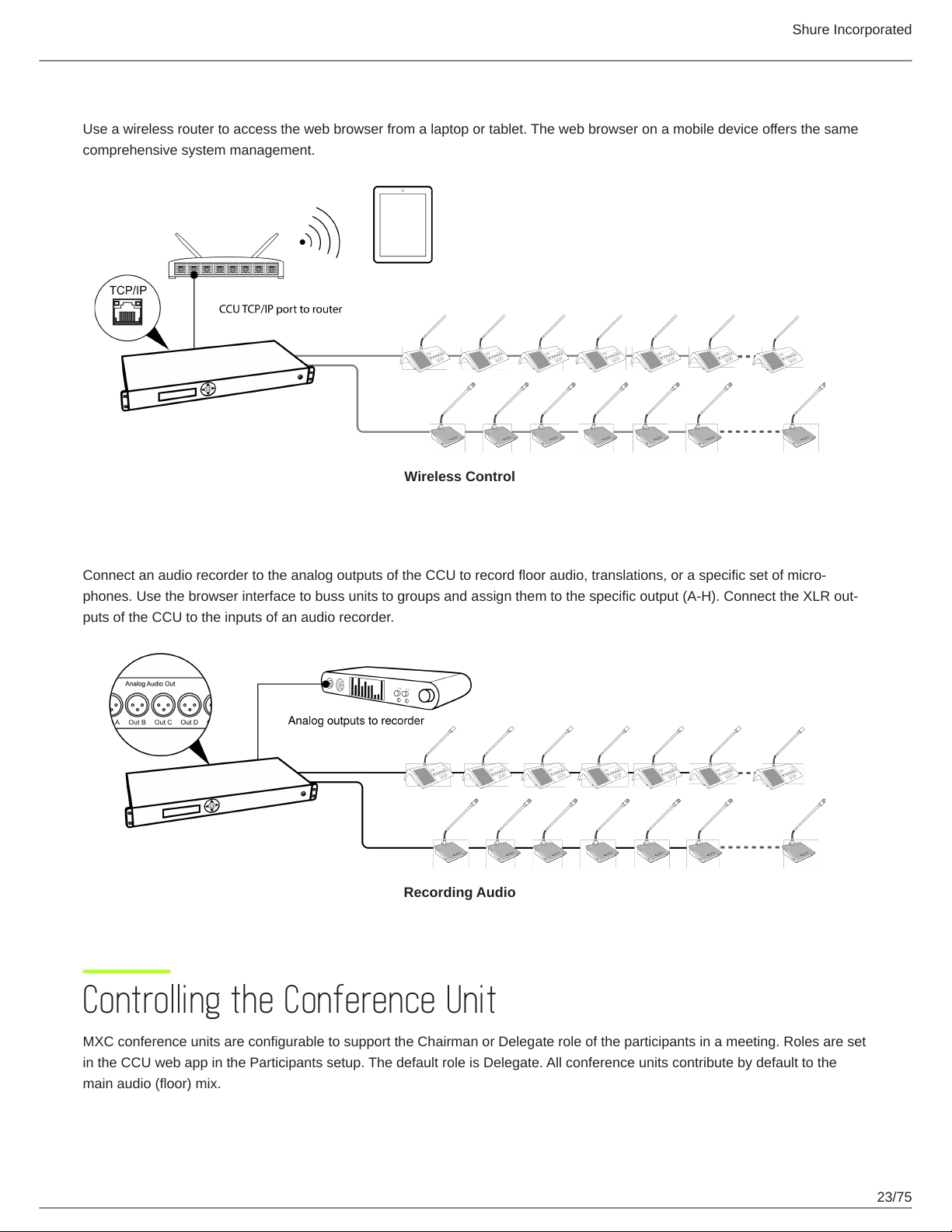
Tablet or Laptop for Wireless Control
Use a wireless router to access the web browser from a laptop or tablet. The web browser on a mobile device offers the same
comprehensive system management.
Wireless Control
Audio Recorder
Connect an audio recorder to the analog outputs of the CCU to record floor audio, translations, or a specific set of micro-
phones. Use the browser interface to buss units to groups and assign them to the specific output (A-H). Connect the XLR out-
puts of the CCU to the inputs of an audio recorder.
Recording Audio
Controlling the Conference Unit
MXC conference units are configurable to support the Chairman or Delegate role of the participants in a meeting. Roles are set
in the CCU web app in the Participants setup. The default role is Delegate. All conference units contribute by default to the
main audio (floor) mix.
23/75
Page 24
Shure Incorporated
Chairman Role
As the leader of the event, the chairman has several unique features enabled on the Conference Unit.
•
Speak button: Turns on the microphone. The chairman can always turn on the microphone, overriding delegate units as
long as the maximum number of open microphones has not been exceeded.
Note: Microphone status is displayed by the button and microphone LEDs:
◦
Red = microphone is on
•
Function button: The chairman's function button can be programmed to the following functions:
◦
Mute: Mutes the audio from the microphone.
◦
Mute all: Mutes the audio from all open delegate microphones.
◦
All delegates off: Turns off all delegate microphones.
◦
Exclusive: Mutes all delegate microphones and activates the chairman microphone (delegate microphones are unmut-
ed when released)
◦
Next on: Turns on the first request on the request list
◦
Reply: Places the chairman in the Reply list (if the speak mode supports Reply functionality).
Delegate Role
The number of simultaneous delegate speakers is limited, requiring different control buttons to participate in the discussion:
•
Speak button: Turns on the microphone or adds the user to the request queue, depending on the speak mode.
Note: Microphone status is displayed by the button and microphone LEDs:
◦
Red = microphone is on
◦
Green = microphone is in the request queue
•
Function button: Delegate function buttons can be programmed to the following functions:
◦
Mute: Temporarily mutes the audio from the microphone.
Note: While the button is pressed, the delegate retains speaking privileges but the microphone will not pass audio.
◦
Reply: The reply functionality places the participant in the Reply list if the speak mode supports Reply
Dual Delegate Role
In this configuration, two participants are sharing a single conference unit. Both the left and right buttons are configured as
Speak buttons, one for each participant.
Dual delegate functionality can be configured on the following units through the CCU:
•
MXC615
Note: Mute and Reply functionality is disabled in dual delegate mode
•
MXC620
Note: Mute and Reply functionality is disabled in dual delegate mode
•
MXC640
•
MXCMIU
The microphone and loudspeaker are shared on MXC615, MXC620 and MXC640 dual units. MXCMIU dual units support indi-
vidual front plates for each participant.
24/75
Page 25
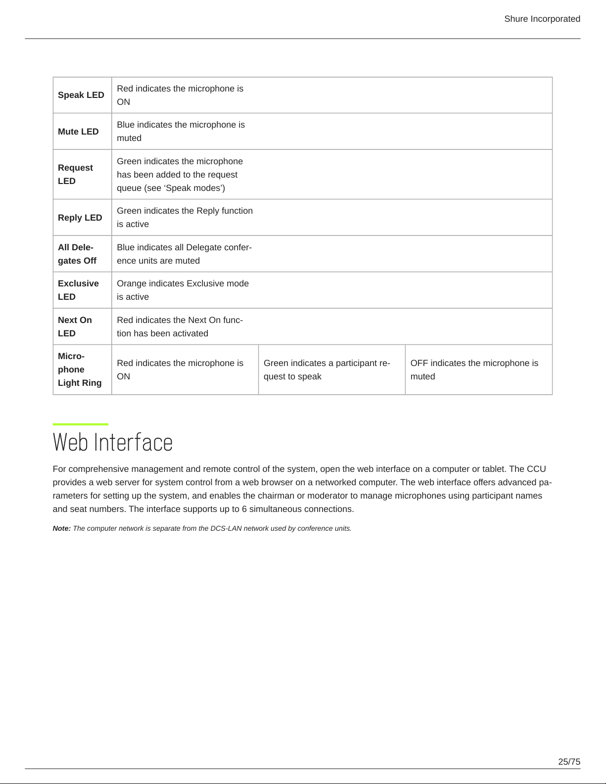
User Indications
Shure Incorporated
Speak LED
Mute LED
Request
LED
Reply LED
All Dele-
gates Off
Exclusive
LED
Next On
LED
Micro-
phone
Light Ring
Red indicates the microphone is
ON
Blue indicates the microphone is
muted
Green indicates the microphone
has been added to the request
queue (see ‘Speak modes’)
Green indicates the Reply function
is active
Blue indicates all Delegate confer-
ence units are muted
Orange indicates Exclusive mode
is active
Red indicates the Next On func-
tion has been activated
Red indicates the microphone is ONGreen indicates a participant re-
quest to speak
OFF indicates the microphone is
muted
Web Interface
For comprehensive management and remote control of the system, open the web interface on a computer or tablet. The CCU
provides a web server for system control from a web browser on a networked computer. The web interface offers advanced pa-
rameters for setting up the system, and enables the chairman or moderator to manage microphones using participant names
and seat numbers. The interface supports up to 6 simultaneous connections.
Note: The computer network is separate from the DCS-LAN network used by conference units.
25/75
Page 26
Shure Incorporated
System Requirements
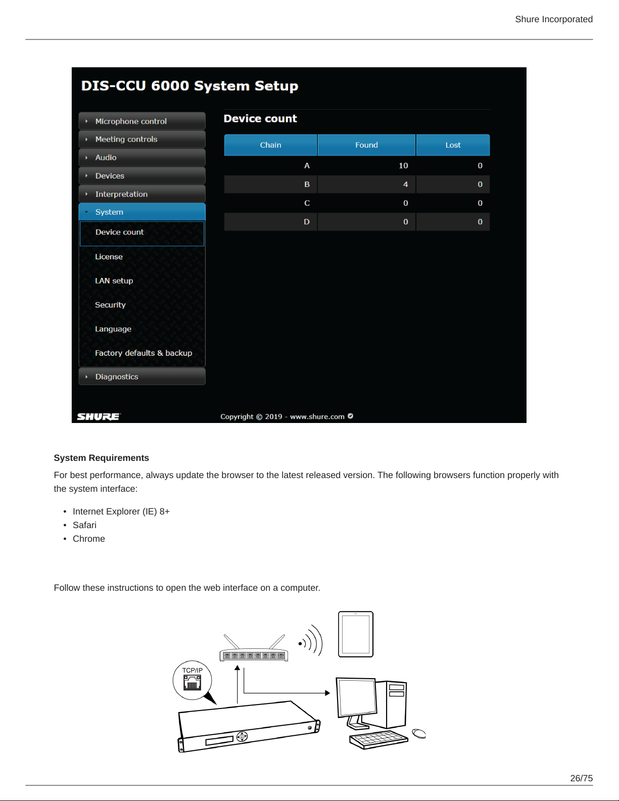
For best performance, always update the browser to the latest released version. The following browsers function properly with
the system interface:
•
Internet Explorer (IE) 8+
•
Safari
•
Chrome
Open the CCU Web Interface
Follow these instructions to open the web interface on a computer.
26/75
Page 27
Shure Incorporated
Connect to the CCU
1.
Connect the computer to the TCP/IP port on the CCU.
2.
Power on the equipment.
3.
Assign the computer to automatically obtain an IP address. This enables the computer to automatically connect to the
CCU.
4.
Acquire an IP address by selecting LAN Setup > IP address mode > Dynamic.
5.
View the IP address: LAN Setup > IP address.
6.
Open the web browser on the computer.
7.
Type http://IP-address, where "IP address" is the address noted from the CCU.
8.
The browser interface opens the Admin screen.
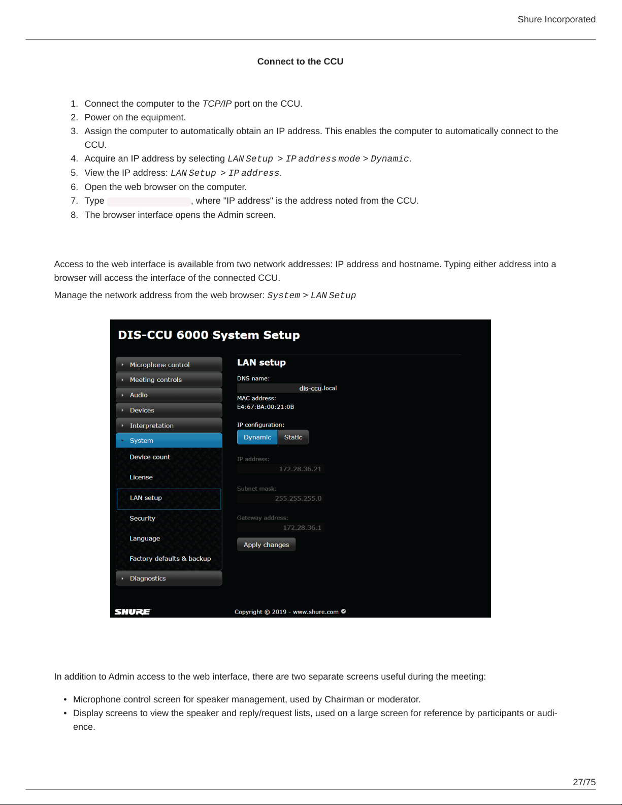
Assigning the Network Address
Access to the web interface is available from two network addresses: IP address and hostname. Typing either address into a
browser will access the interface of the connected CCU.
Manage the network address from the web browser: System > LAN Setup
Additional Screens
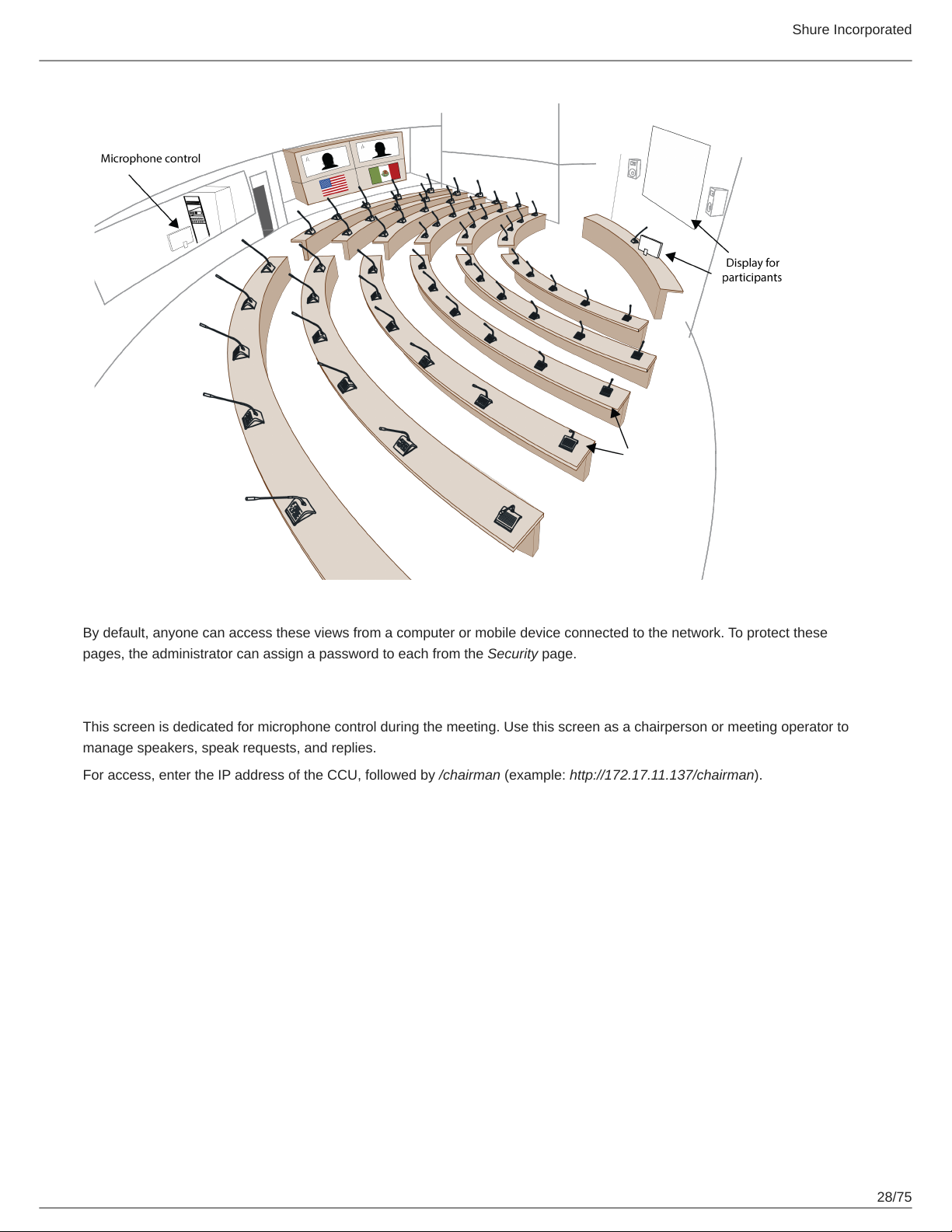
In addition to Admin access to the web interface, there are two separate screens useful during the meeting:
•
Microphone control screen for speaker management, used by Chairman or moderator.
•
Display screens to view the speaker and reply/request lists, used on a large screen for reference by participants or audi-
ence.
27/75
Page 28
Shure Incorporated
By default, anyone can access these views from a computer or mobile device connected to the network. To protect these
pages, the administrator can assign a password to each from the Security page.
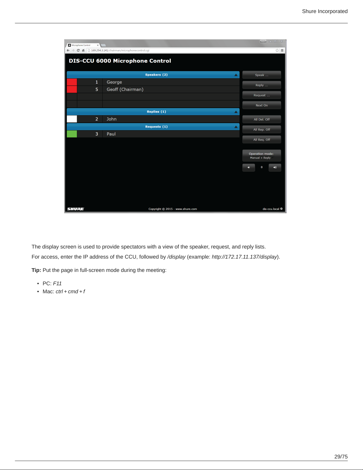
Microphone Control Screen
This screen is dedicated for microphone control during the meeting. Use this screen as a chairperson or meeting operator to
manage speakers, speak requests, and replies.
For access, enter the IP address of the CCU, followed by /chairman (example: http://172.17.11.137/chairman).
28/75
Page 29
Shure Incorporated
Display Screen
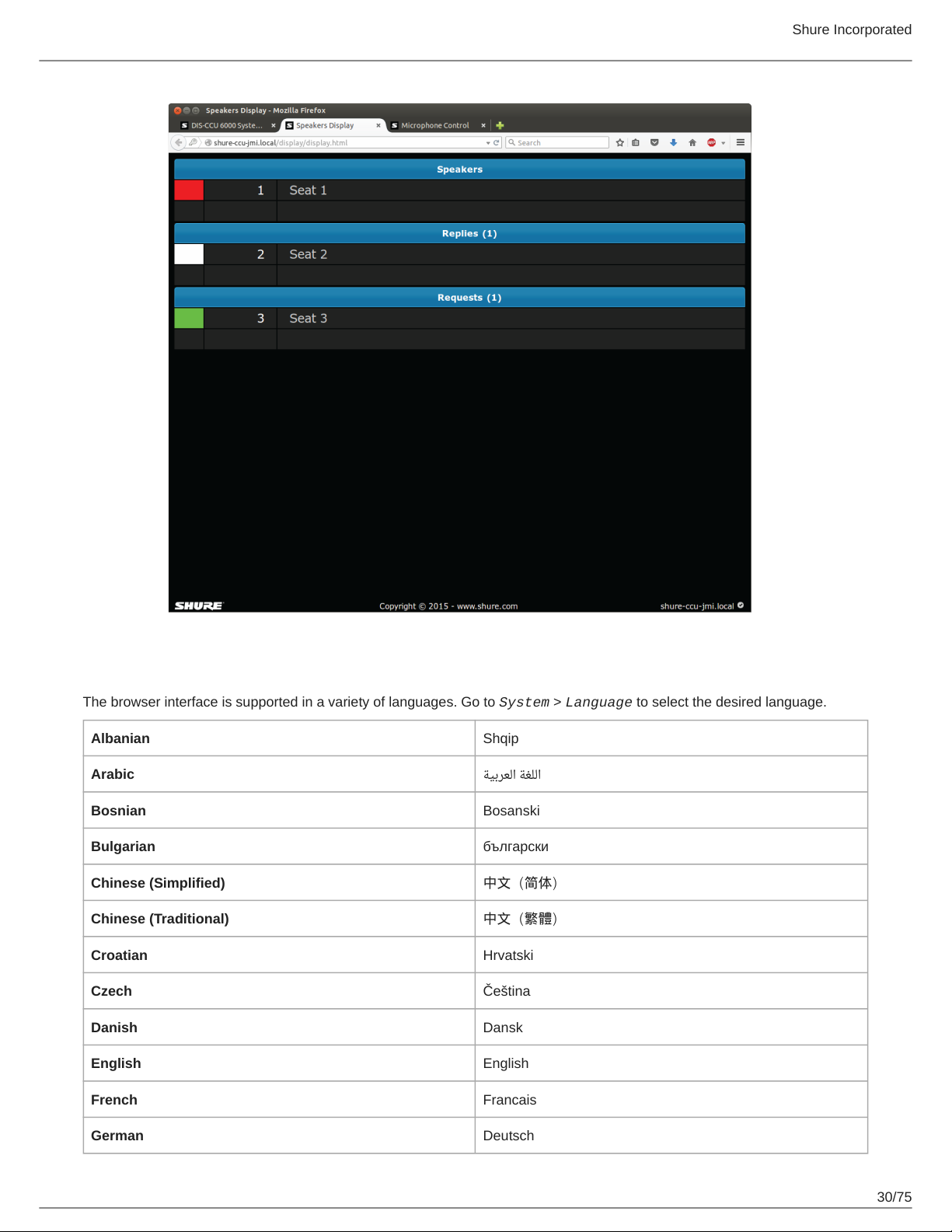
The display screen is used to provide spectators with a view of the speaker, request, and reply lists.
For access, enter the IP address of the CCU, followed by /display (example: http://172.17.11.137/display).
Tip: Put the page in full-screen mode during the meeting:
•
PC: F11
•
Mac: ctrl + cmd + f
29/75
Page 30
Shure Incorporated
Language Setting
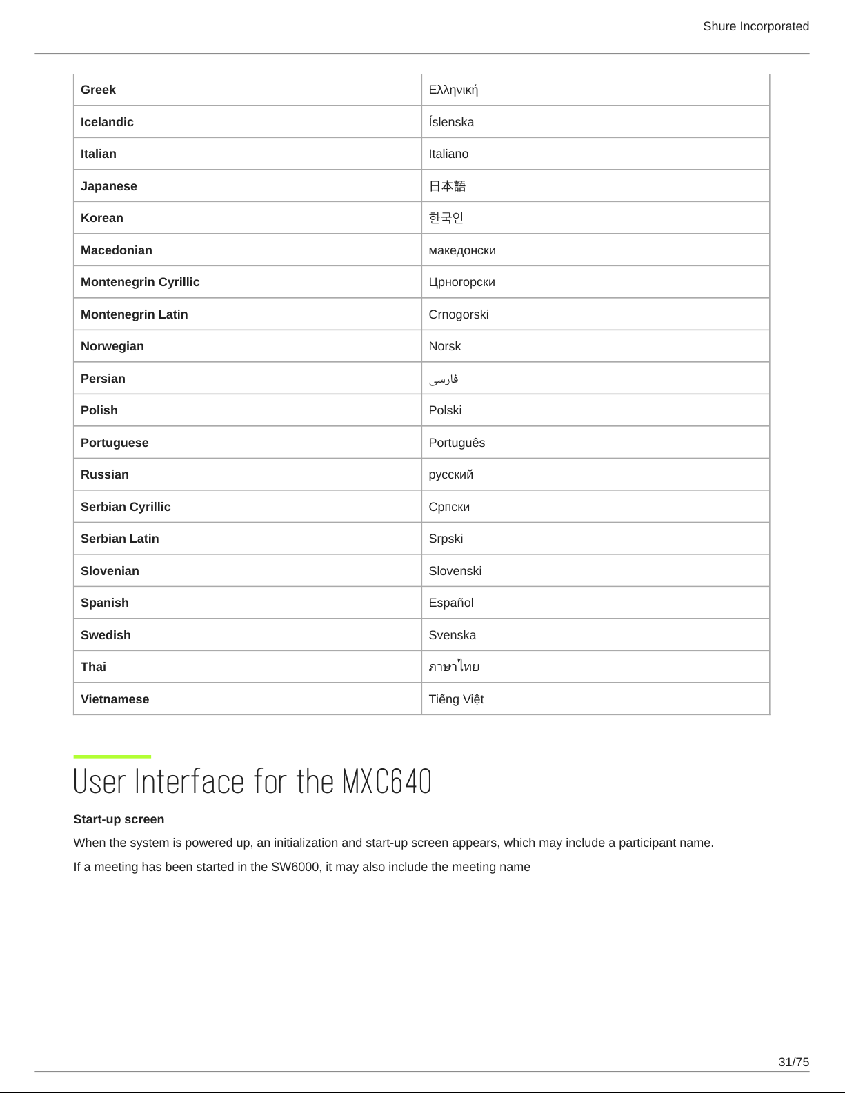
The browser interface is supported in a variety of languages. Go to System > Language to select the desired language.
Albanian Shqip
Arabic ﺔﻴﺑﺮﻌﻟﺍ ﺔﻐﻠﻟﺍ
Bosnian Bosanski
Bulgarian български
Chinese (Simplified) 中文(简体)
Chinese (Traditional) 中文(繁體)
Croatian Hrvatski
Czech Čeština
Danish Dansk
English English
French Francais
German Deutsch
30/75
Page 31
Greek Ελληνική
Icelandic Íslenska
Italian Italiano
Japanese 日本語
Korean 한국인
Macedonian македонски
Montenegrin Cyrillic Црногорски
Montenegrin Latin Crnogorski
Norwegian Norsk
Persian ﯽﺳﺭﺎﻓ
Polish Polski
Shure Incorporated
Portuguese Português
Russian русский
Serbian Cyrillic Српски
Serbian Latin Srpski
Slovenian Slovenski
Spanish Español
Swedish Svenska
Thai ภาษาไทย
Vietnamese Tiếng Việt
User Interface for the MXC640
Start-up screen
When the system is powered up, an initialization and start-up screen appears, which may include a participant name.
If a meeting has been started in the SW6000, it may also include the meeting name
31/75
Page 32
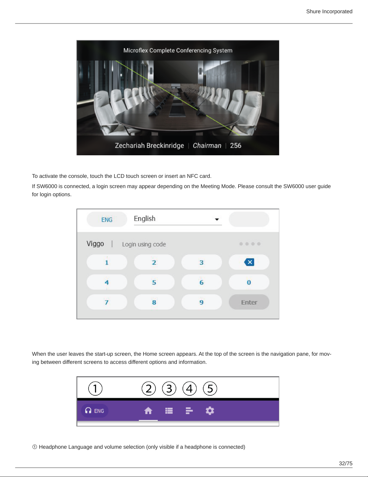
To activate the console, touch the LCD touch screen or insert an NFC card.
Shure Incorporated
If SW6000 is connected, a login screen may appear depending on the Meeting Mode. Please consult the SW6000 user guide
for login options.
Navigation Pane
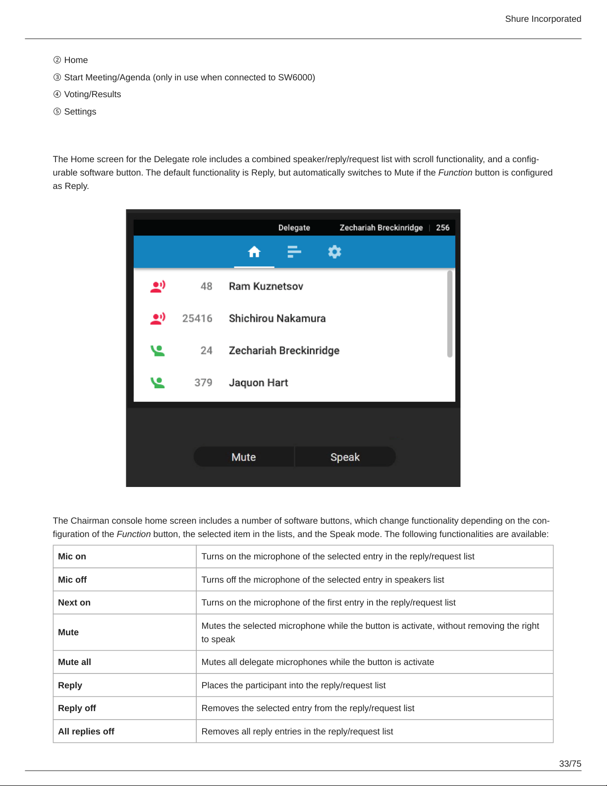
When the user leaves the start-up screen, the Home screen appears. At the top of the screen is the navigation pane, for mov-
ing between different screens to access different options and information.
① Headphone Language and volume selection (only visible if a headphone is connected)
32/75
Page 33
Shure Incorporated
② Home
③ Start Meeting/Agenda (only in use when connected to SW6000)
④ Voting/Results
⑤ Settings
Home Screen
The Home screen for the Delegate role includes a combined speaker/reply/request list with scroll functionality, and a config-
urable software button. The default functionality is Reply, but automatically switches to Mute if the Function button is configured
as Reply.
The Chairman console home screen includes a number of software buttons, which change functionality depending on the con-
figuration of the Function button, the selected item in the lists, and the Speak mode. The following functionalities are available:
Mic on Turns on the microphone of the selected entry in the reply/request list
Mic off Turns off the microphone of the selected entry in speakers list
Next on Turns on the microphone of the first entry in the reply/request list
Mute
Mute all Mutes all delegate microphones while the button is activate
Reply Places the participant into the reply/request list
Reply off Removes the selected entry from the reply/request list
All replies off Removes all reply entries in the reply/request list
Mutes the selected microphone while the button is activate, without removing the right
to speak
33/75
Page 34
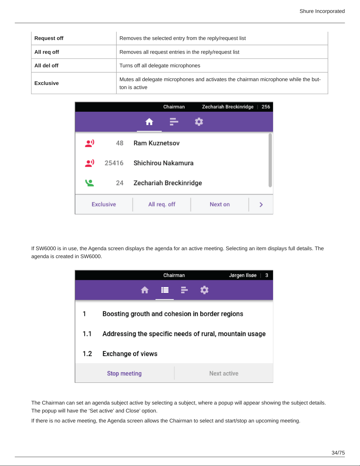
Request off Removes the selected entry from the reply/request list
All req off Removes all request entries in the reply/request list
All del off Turns off all delegate microphones
Shure Incorporated
Exclusive
Mutes all delegate microphones and activates the chairman microphone while the but-
ton is active
Agenda
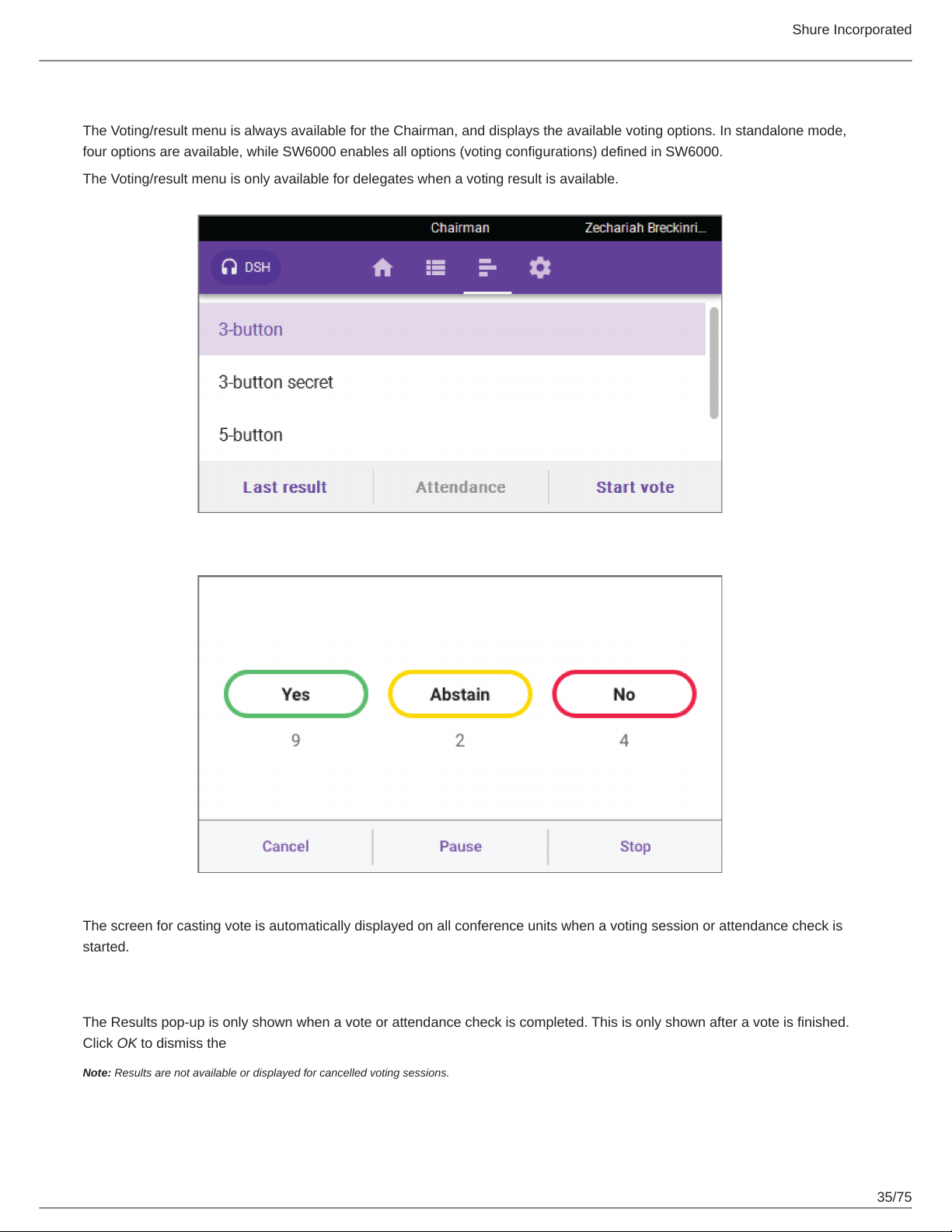
If SW6000 is in use, the Agenda screen displays the agenda for an active meeting. Selecting an item displays full details. The
agenda is created in SW6000.
The Chairman can set an agenda subject active by selecting a subject, where a popup will appear showing the subject details.
The popup will have the ‘Set active’ and Close’ option.
If there is no active meeting, the Agenda screen allows the Chairman to select and start/stop an upcoming meeting.
34/75
Page 35
Shure Incorporated
Voting/Result Menu
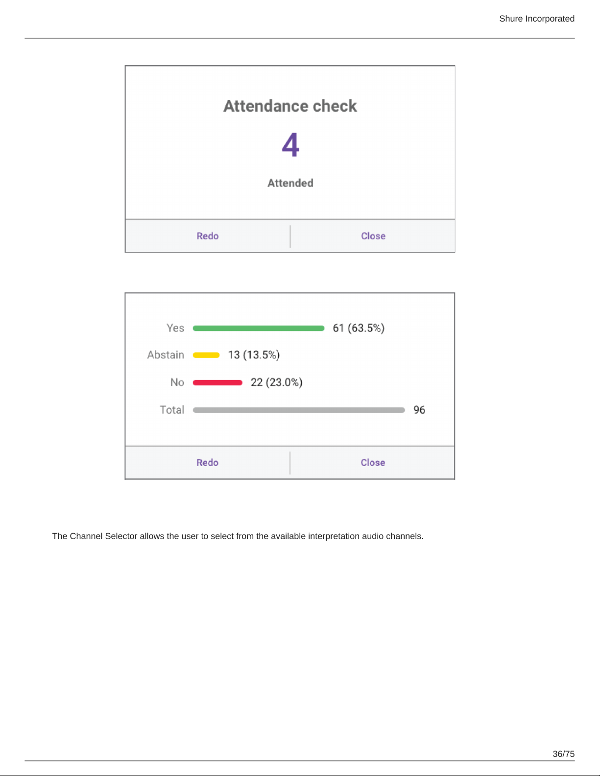
The Voting/result menu is always available for the Chairman, and displays the available voting options. In standalone mode,
four options are available, while SW6000 enables all options (voting configurations) defined in SW6000.
The Voting/result menu is only available for delegates when a voting result is available.
The screen for casting vote is automatically displayed on all conference units when a voting session or attendance check is
started.
Results
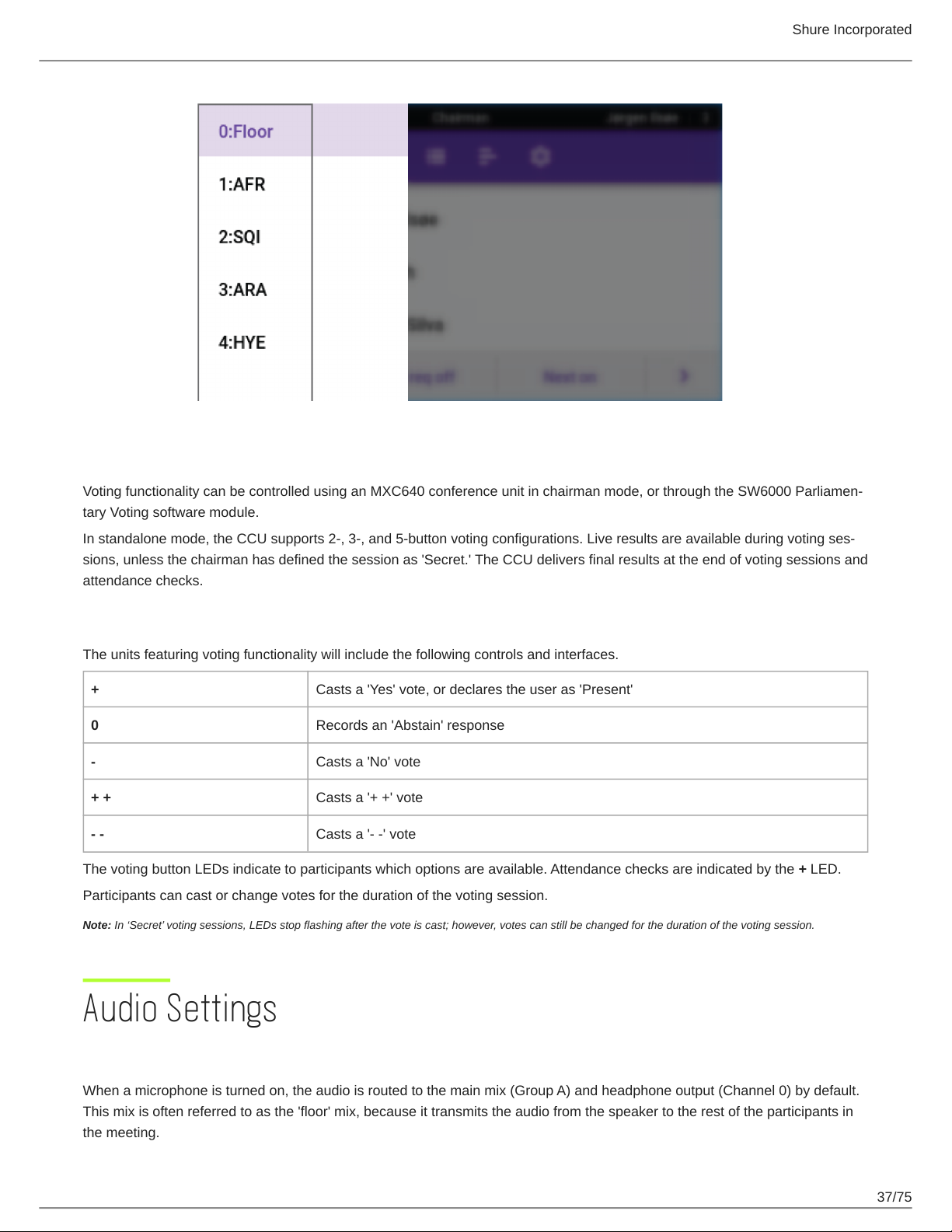
The Results pop-up is only shown when a vote or attendance check is completed. This is only shown after a vote is finished.
Click OK to dismiss the
Note: Results are not available or displayed for cancelled voting sessions.
35/75
Page 36
Shure Incorporated
Channel Selector
The Channel Selector allows the user to select from the available interpretation audio channels.
36/75
Page 37
Shure Incorporated
Voting Functionality
Voting functionality can be controlled using an MXC640 conference unit in chairman mode, or through the SW6000 Parliamen-
tary Voting software module.
In standalone mode, the CCU supports 2-, 3-, and 5-button voting configurations. Live results are available during voting ses-
sions, unless the chairman has defined the session as 'Secret.' The CCU delivers final results at the end of voting sessions and
attendance checks.
User Controls & Indications
The units featuring voting functionality will include the following controls and interfaces.
+ Casts a 'Yes' vote, or declares the user as 'Present'
0 Records an 'Abstain' response
- Casts a 'No' vote
+ + Casts a '+ +' vote
- - Casts a '- -' vote
The voting button LEDs indicate to participants which options are available. Attendance checks are indicated by the + LED.
Participants can cast or change votes for the duration of the voting session.
Note: In ‘Secret’ voting sessions, LEDs stop flashing after the vote is cast; however, votes can still be changed for the duration of the voting session.
Audio Settings
Microphone Functionality
When a microphone is turned on, the audio is routed to the main mix (Group A) and headphone output (Channel 0) by default.
This mix is often referred to as the 'floor' mix, because it transmits the audio from the speaker to the rest of the participants in
the meeting.
37/75
Page 38
Shure Incorporated
The number of allowed open microphones can be set at the CCU. The sound from all the open microphones is combined in the
floor mix. The floor mix can be listened to on connected conference units and interpreter consoles, or sent to an external PA
system.
Route Microphones to Groups
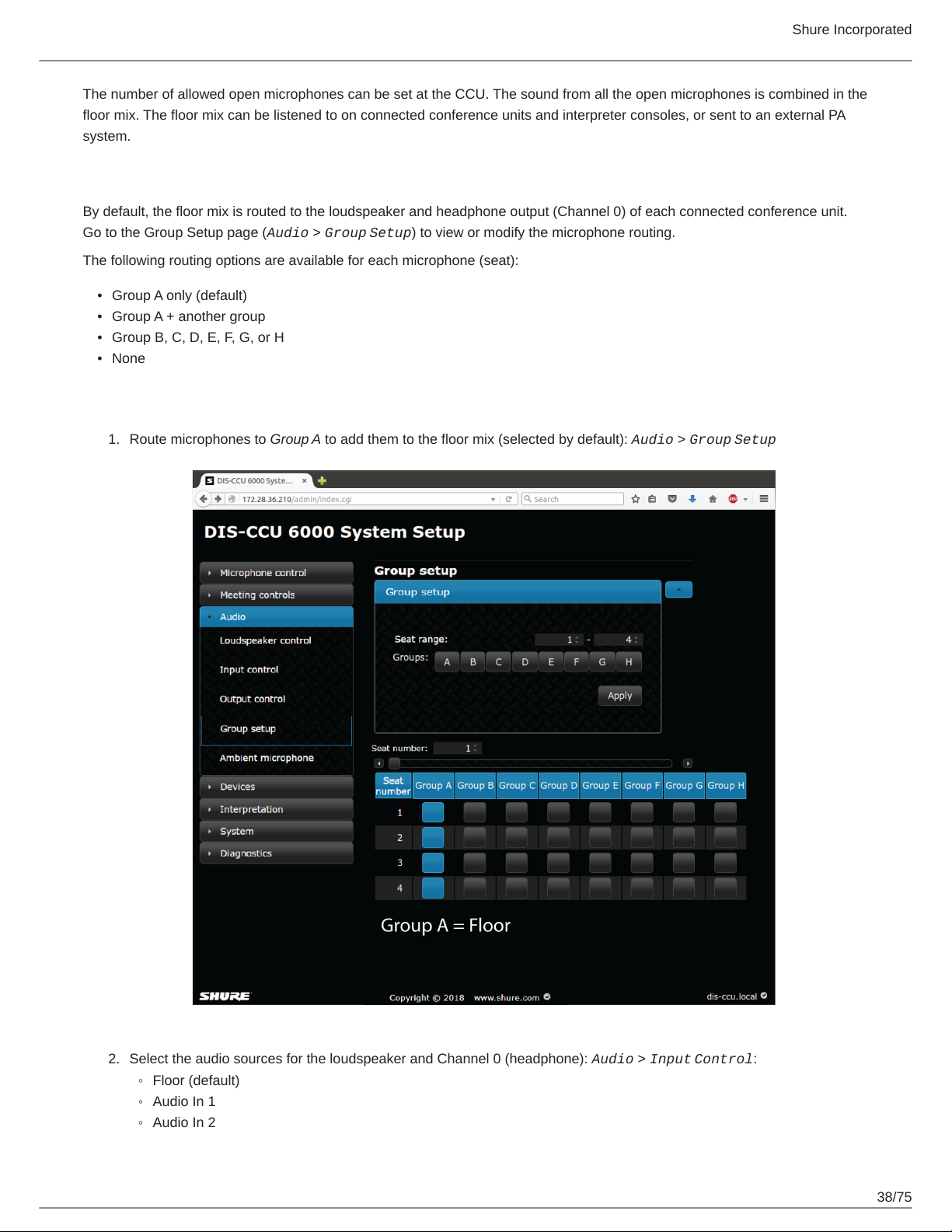
By default, the floor mix is routed to the loudspeaker and headphone output (Channel 0) of each connected conference unit.
Go to the Group Setup page (Audio > Group Setup) to view or modify the microphone routing.
The following routing options are available for each microphone (seat):
•
Group A only (default)
•
Group A + another group
•
Group B, C, D, E, F, G, or H
•
None
To change the audio source:
1.
Route microphones to Group A to add them to the floor mix (selected by default): Audio > Group Setup
2.
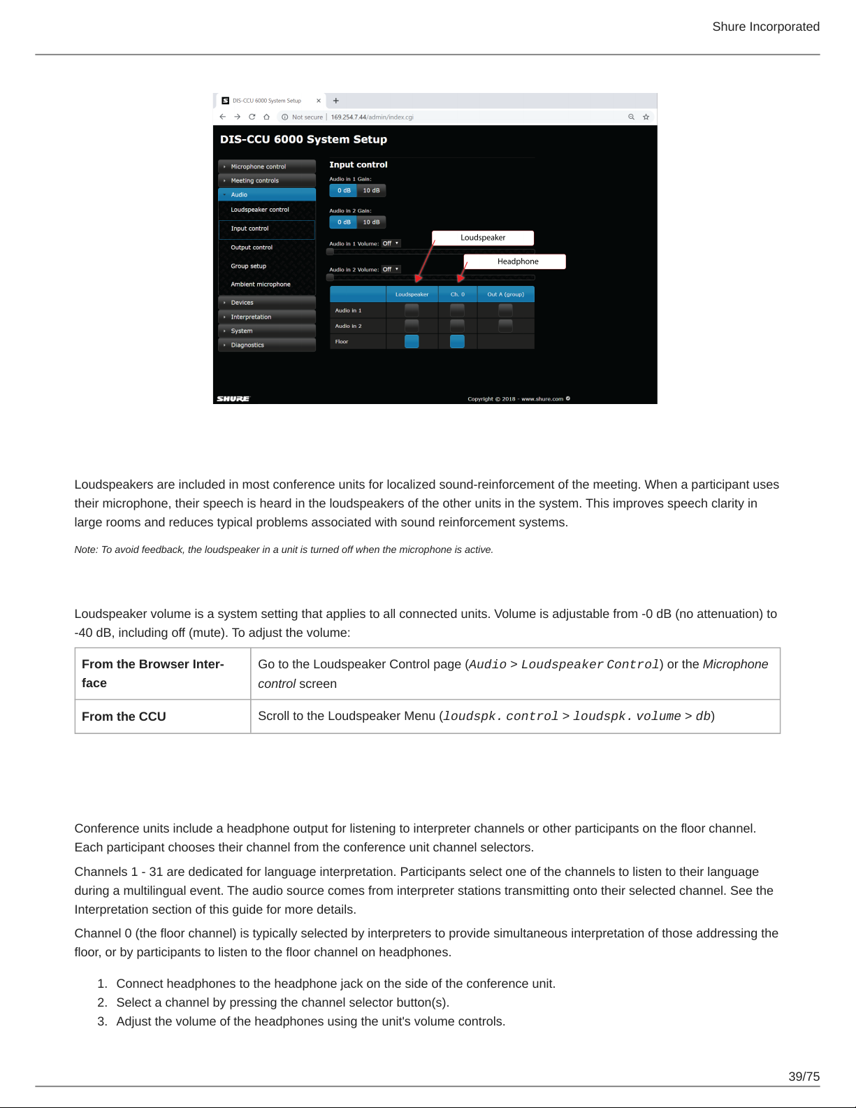
Select the audio sources for the loudspeaker and Channel 0 (headphone): Audio > Input Control:
◦
Floor (default)
◦
Audio In 1
◦
Audio In 2
38/75
Page 39
Shure Incorporated
Floor Mix on the Loudspeakers
Loudspeakers are included in most conference units for localized sound-reinforcement of the meeting. When a participant uses
their microphone, their speech is heard in the loudspeakers of the other units in the system. This improves speech clarity in
large rooms and reduces typical problems associated with sound reinforcement systems.
Note: To avoid feedback, the loudspeaker in a unit is turned off when the microphone is active.
Loudspeaker Adjustment
Loudspeaker volume is a system setting that applies to all connected units. Volume is adjustable from -0 dB (no attenuation) to
-40 dB, including off (mute). To adjust the volume:
From the Browser Inter-
face
From the CCU
Go to the Loudspeaker Control page (Audio > Loudspeaker Control) or the Microphone
control screen
Scroll to the Loudspeaker Menu (loudspk. control > loudspk. volume > db)
Headphone Channels
Conference units include a headphone output for listening to interpreter channels or other participants on the floor channel.
Each participant chooses their channel from the conference unit channel selectors.
Channels 1 - 31 are dedicated for language interpretation. Participants select one of the channels to listen to their language
during a multilingual event. The audio source comes from interpreter stations transmitting onto their selected channel. See the
Interpretation section of this guide for more details.
Channel 0 (the floor channel) is typically selected by interpreters to provide simultaneous interpretation of those addressing the
floor, or by participants to listen to the floor channel on headphones.
1.
Connect headphones to the headphone jack on the side of the conference unit.
2.
Select a channel by pressing the channel selector button(s).
3.
Adjust the volume of the headphones using the unit's volume controls.
39/75
Page 40
Shure Incorporated
Analog Audio Outputs
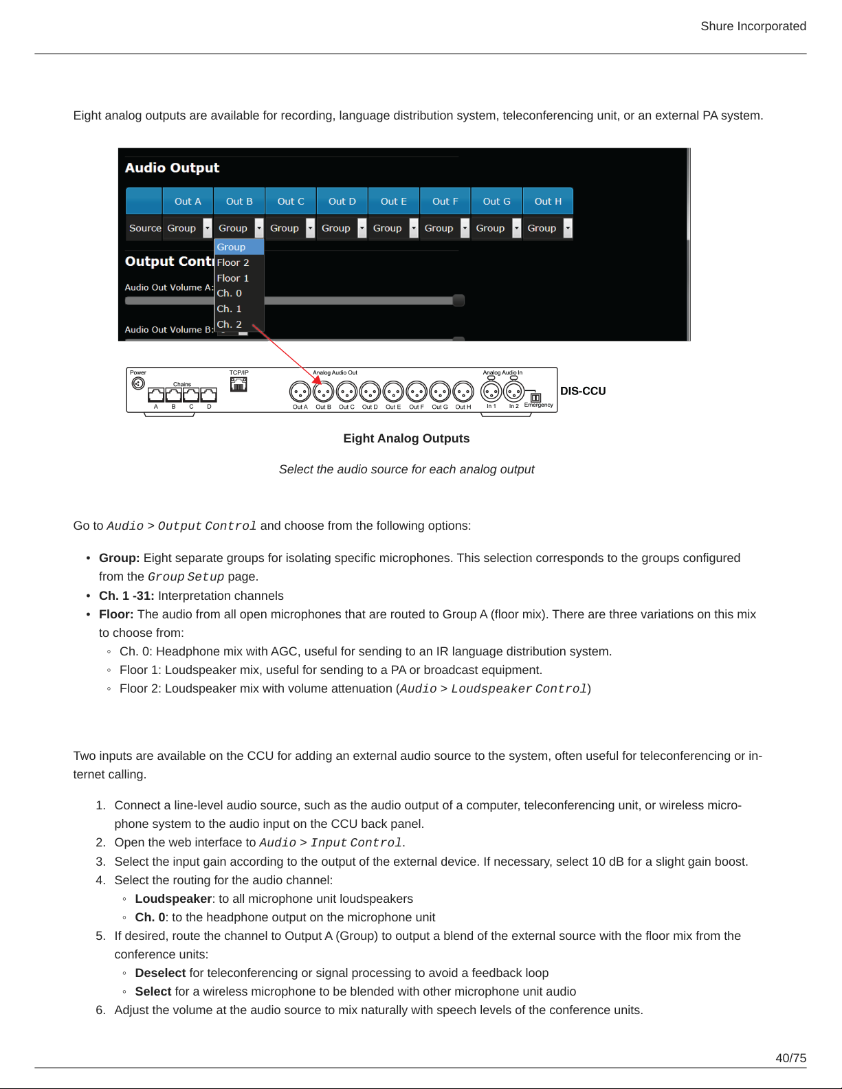
Eight analog outputs are available for recording, language distribution system, teleconferencing unit, or an external PA system.
Eight Analog Outputs
Select the audio source for each analog output
Go to Audio > Output Control and choose from the following options:
•
Group: Eight separate groups for isolating specific microphones. This selection corresponds to the groups configured
from the Group Setup page.
•
Ch. 1 -31: Interpretation channels
•
Floor: The audio from all open microphones that are routed to Group A (floor mix). There are three variations on this mix
to choose from:
◦
Ch. 0: Headphone mix with AGC, useful for sending to an IR language distribution system.
◦
Floor 1: Loudspeaker mix, useful for sending to a PA or broadcast equipment.
◦
Floor 2: Loudspeaker mix with volume attenuation (Audio > Loudspeaker Control)
Adding an External Audio Source
Two inputs are available on the CCU for adding an external audio source to the system, often useful for teleconferencing or in-
ternet calling.
1.
Connect a line-level audio source, such as the audio output of a computer, teleconferencing unit, or wireless micro-
phone system to the audio input on the CCU back panel.
2.
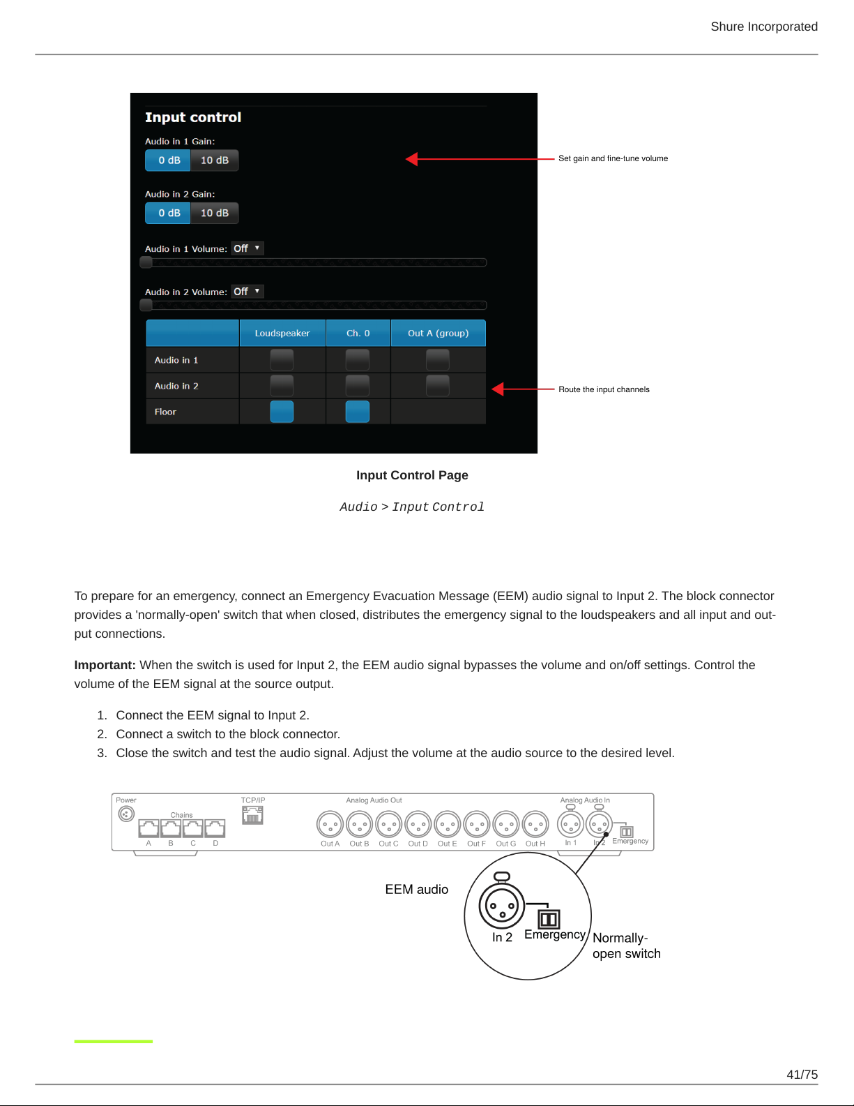
Open the web interface to Audio > Input Control.
3.
Select the input gain according to the output of the external device. If necessary, select 10 dB for a slight gain boost.
4.
Select the routing for the audio channel:
◦
Loudspeaker: to all microphone unit loudspeakers
◦
Ch. 0: to the headphone output on the microphone unit
5.
If desired, route the channel to Output A (Group) to output a blend of the external source with the floor mix from the
conference units:
◦
Deselect for teleconferencing or signal processing to avoid a feedback loop
◦
Select for a wireless microphone to be blended with other microphone unit audio
6.
Adjust the volume at the audio source to mix naturally with speech levels of the conference units.
40/75
Page 41
Shure Incorporated
Input Control Page
Audio > Input Control
Emergency Audio Signal
To prepare for an emergency, connect an Emergency Evacuation Message (EEM) audio signal to Input 2. The block connector
provides a 'normally-open' switch that when closed, distributes the emergency signal to the loudspeakers and all input and out-
put connections.
Important: When the switch is used for Input 2, the EEM audio signal bypasses the volume and on/off settings. Control the
volume of the EEM signal at the source output.
1.
Connect the EEM signal to Input 2.
2.
Connect a switch to the block connector.
3.
Close the switch and test the audio signal. Adjust the volume at the audio source to the desired level.
41/75
Page 42
Shure Incorporated
Meeting Configuration
Names, Roles and Seat Numbers
When a meeting begins, the chairman or moderator will need to refer to the participants by either name, seat number, or both.
The proper assignment of names and seat numbers is critical to ensure the continuity of the meeting.
Assigning Seat Numbers
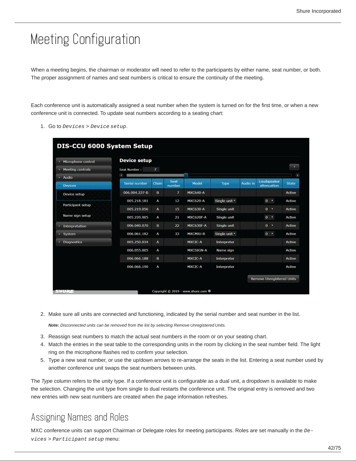
Each conference unit is automatically assigned a seat number when the system is turned on for the first time, or when a new
conference unit is connected. To update seat numbers according to a seating chart:
1.
Go to Devices > Device setup.
2.
Make sure all units are connected and functioning, indicated by the serial number and seat number in the list.
Note: Disconnected units can be removed from the list by selecting Remove Unregistered Units.
3.
Reassign seat numbers to match the actual seat numbers in the room or on your seating chart.
4.
Match the entries in the seat table to the corresponding units in the room by clicking in the seat number field. The light
ring on the microphone flashes red to confirm your selection.
5.
Type a new seat number, or use the up/down arrows to re-arrange the seats in the list. Entering a seat number used by
another conference unit swaps the seat numbers between units.
The Type column refers to the unity type. If a conference unit is configurable as a dual unit, a dropdown is available to make
the selection. Changing the unit type from single to dual restarts the conference unit. The original entry is removed and two
new entries with new seat numbers are created when the page information refreshes.
Assigning Names and Roles
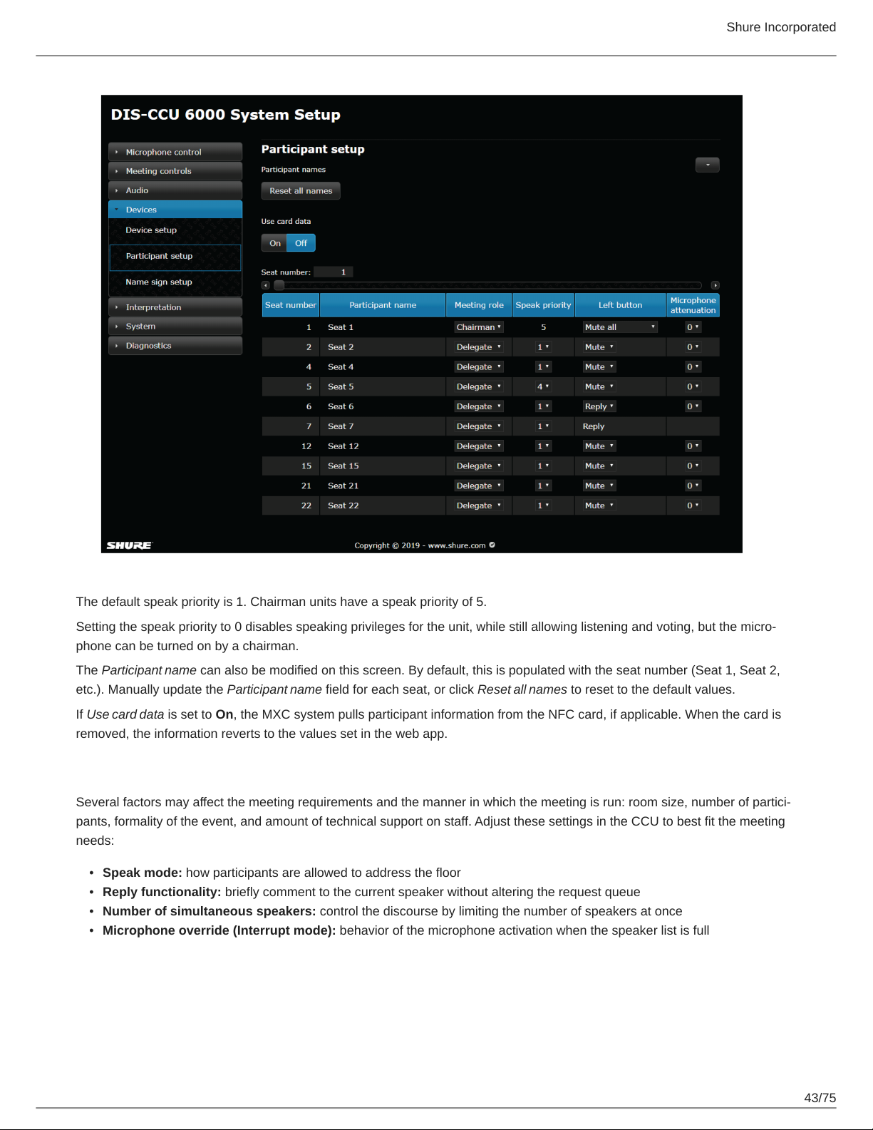
MXC conference units can support Chairman or Delegate roles for meeting participants. Roles are set manually in the De
vices > Participant setup menu:
42/75
Page 43
Shure Incorporated
The default speak priority is 1. Chairman units have a speak priority of 5.
Setting the speak priority to 0 disables speaking privileges for the unit, while still allowing listening and voting, but the micro-
phone can be turned on by a chairman.
The Participant name can also be modified on this screen. By default, this is populated with the seat number (Seat 1, Seat 2,
etc.). Manually update the Participant name field for each seat, or click Reset all names to reset to the default values.
If Use card data is set to On, the MXC system pulls participant information from the NFC card, if applicable. When the card is
removed, the information reverts to the values set in the web app.
Meeting Controls
Several factors may affect the meeting requirements and the manner in which the meeting is run: room size, number of partici-
pants, formality of the event, and amount of technical support on staff. Adjust these settings in the CCU to best fit the meeting
needs:
•
Speak mode: how participants are allowed to address the floor
•
Reply functionality: briefly comment to the current speaker without altering the request queue
•
Number of simultaneous speakers: control the discourse by limiting the number of speakers at once
•
Microphone override (Interrupt mode): behavior of the microphone activation when the speaker list is full
43/75
Page 44
Microphone Settings
Shure Incorporated
Speak Mode
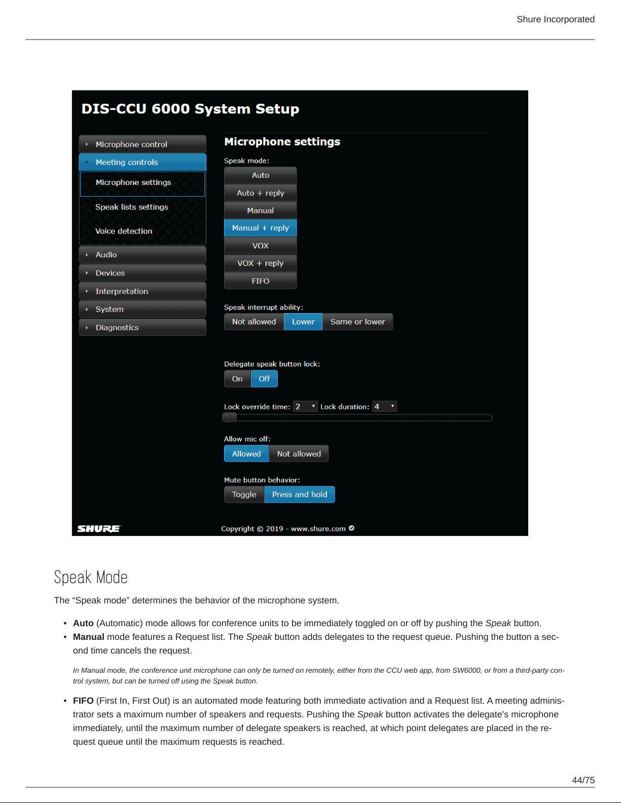
The “Speak mode” determines the behavior of the microphone system.
•
Auto (Automatic) mode allows for conference units to be immediately toggled on or off by pushing the Speak button.
•
Manual mode features a Request list. The Speak button adds delegates to the request queue. Pushing the button a sec-
ond time cancels the request.
In Manual mode, the conference unit microphone can only be turned on remotely, either from the CCU web app, from SW6000, or from a third-party con-
trol system, but can be turned off using the Speak button.
•
FIFO (First In, First Out) is an automated mode featuring both immediate activation and a Request list. A meeting adminis-
trator sets a maximum number of speakers and requests. Pushing the Speak button activates the delegate's microphone
immediately, until the maximum number of delegate speakers is reached, at which point delegates are placed in the re-
quest queue until the maximum requests is reached.
44/75
Page 45
Shure Incorporated
When an active unit is switched off, the first unit in the queue turns on automatically. The Request indicator flashes when
the conference unit is at the top of the queue and is the next to be switched on.
•
VOX (voice activation) mode allows conference units to be switched on automatically when a delegate is speaking in the
microphone, as well as toggled on or off using the Speak button. The microphone also turns off automatically after 4 sec-
onds.
Dual units do not support VOX. If VOX is selected, a dual unit will operate in Auto mode. Chairman units are always in Au-
to or VOX mode.
Note: VOX is available in legacy DCS units, and support for MXC is planned for a future firmware update.
Speak Interrupt Ability
The Speak interrupt ability setting determines when a participant can interrupt (turn off) other active speakers by turning on
their own microphone, if the number of active microphones reaches the limits set under Max. speakers: Delegates and Max.
speakers: Total.
•
Not allowed: When the number of open delegate microphones reaches the Max. speakers: Delegates limit, or the number
of open chairman microphones reaches the Max. speakers: Total limit, no more delegate/chairman microphones can be
opened and the green LED will flash 3 times.
Note: When the Max. speakers: Delegates limit is met but the Max. speakers: Totallimit is not, a chairman can interrupt the first delegate added to the
Speak list.
•
Lower: When the Max. speakers: Delegates limit is reached, a speaker interrupts the first delegate added to the speak list
with lower priority.
•
Same or lower: Any participant can interrupt the first delegate added to the Speak list with the same or lower priority
when the Max. speakers limit is reached. If only chairman microphones are active, a chairman can interrupt the first chair-
man added to the Speak list.
Individual priority settings can be manually determined in the Speak priority column under Devices > Participant setup.
Speak Button Lock
When controlling microphones remotely, the Speak button can be temporarily disabled to avoid unintentional activation by the
delegate.
Speak button lock is Off by default. When turned On, only units/users with speak priority 0-4 are locked. Remote commands
from TCP/IP, SW6000, and units with microphone control permission are not affected.
Lock duration is the amount of time the button's toggle functionality is affected.
•
Ranges from 2 to 120 seconds, in 1-second intervals
•
After this time, functionality returns to normal
Lock override time is the amount of time (in seconds) that the Speak button must be held for the speaker to bypass the lock.
•
Ranges from 1 to 120 seconds, in 1-second intervals
•
Can never be longer than the Lock duration time
Allow Mic Off
This determines whether a delegate can turn his or her microphone off. The option defaults to Allowed.
When set to Not allowed, only a participant with microphone control permission (Chairman) can turn off the microphone.
45/75
Page 46
Shure Incorporated
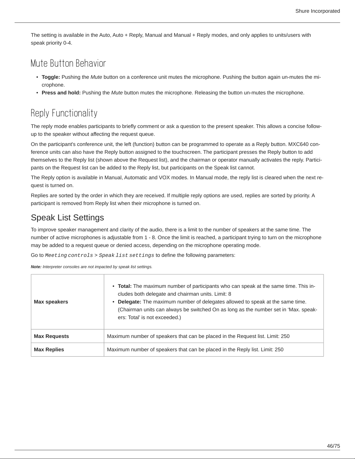
The setting is available in the Auto, Auto + Reply, Manual and Manual + Reply modes, and only applies to units/users with
speak priority 0-4.
Mute Button Behavior
•
Toggle: Pushing the Mute button on a conference unit mutes the microphone. Pushing the button again un-mutes the mi-
crophone.
•
Press and hold: Pushing the Mute button mutes the microphone. Releasing the button un-mutes the microphone.
Reply Functionality
The reply mode enables participants to briefly comment or ask a question to the present speaker. This allows a concise follow-
up to the speaker without affecting the request queue.
On the participant's conference unit, the left (function) button can be programmed to operate as a Reply button. MXC640 con-
ference units can also have the Reply button assigned to the touchscreen. The participant presses the Reply button to add
themselves to the Reply list (shown above the Request list), and the chairman or operator manually activates the reply. Partici-
pants on the Request list can be added to the Reply list, but participants on the Speak list cannot.
The Reply option is available in Manual, Automatic and VOX modes. In Manual mode, the reply list is cleared when the next re-
quest is turned on.
Replies are sorted by the order in which they are received. If multiple reply options are used, replies are sorted by priority. A
participant is removed from Reply list when their microphone is turned on.
Speak List Settings
To improve speaker management and clarity of the audio, there is a limit to the number of speakers at the same time. The
number of active microphones is adjustable from 1 - 8. Once the limit is reached, a participant trying to turn on the microphone
may be added to a request queue or denied access, depending on the microphone operating mode.
Go to Meeting controls > Speak list settings to define the following parameters:
Note: Interpreter consoles are not impacted by speak list settings.
•
Total: The maximum number of participants who can speak at the same time. This in-
cludes both delegate and chairman units. Limit: 8
Max speakers
Max Requests Maximum number of speakers that can be placed in the Request list. Limit: 250
Max Replies Maximum number of speakers that can be placed in the Reply list. Limit: 250
•
Delegate: The maximum number of delegates allowed to speak at the same time.
(Chairman units can always be switched On as long as the number set in ‘Max. speak-
ers: Total’ is not exceeded.)
46/75
Page 47

Shure Incorporated
Example Settings
Chairman (Moderator) Can Speak At Any Time Without Interrupting
Set the Max. speakers: Total limit one (1) higher than Max. speakers: Delegates.
Using FIFO Mode
First In, First Out (FIFO) mode automatically turns on microphones based on a chronological queue list. This mode works best
if Max. speakers: Delegates is set to one (1), so that the delegate must wait to speak until the other is finished.
Voice Detection
Adjust voice detection settings from Meeting controls > Voice detection.
47/75
Page 48
Shure Incorporated
Voice Activation (VOX)
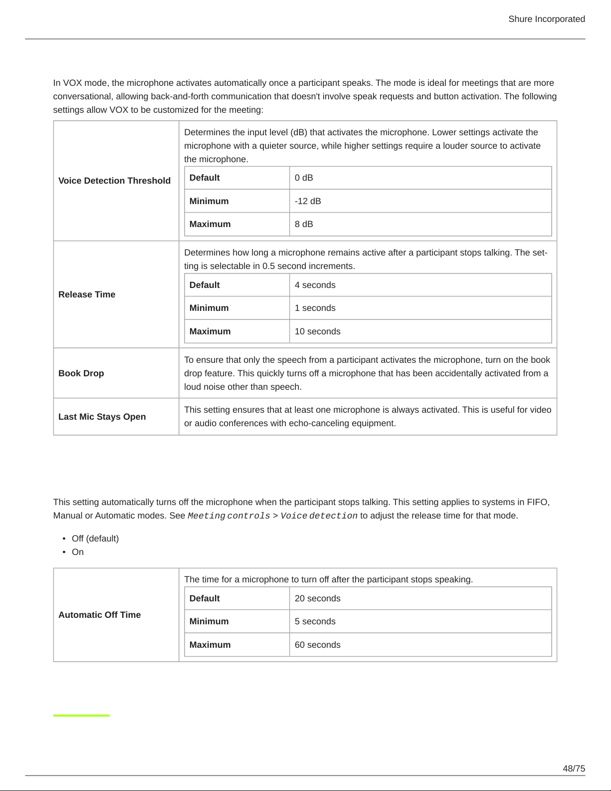
In VOX mode, the microphone activates automatically once a participant speaks. The mode is ideal for meetings that are more
conversational, allowing back-and-forth communication that doesn't involve speak requests and button activation. The following
settings allow VOX to be customized for the meeting:
Determines the input level (dB) that activates the microphone. Lower settings activate the
microphone with a quieter source, while higher settings require a louder source to activate
the microphone.
Voice Detection Threshold
Release Time
Book Drop
Last Mic Stays Open
Default 0 dB
Minimum -12 dB
Maximum 8 dB
Determines how long a microphone remains active after a participant stops talking. The set-
ting is selectable in 0.5 second increments.
Default 4 seconds
Minimum 1 seconds
Maximum 10 seconds
To ensure that only the speech from a participant activates the microphone, turn on the book
drop feature. This quickly turns off a microphone that has been accidentally activated from a
loud noise other than speech.
This setting ensures that at least one microphone is always activated. This is useful for video
or audio conferences with echo-canceling equipment.
Microphone Auto Off
This setting automatically turns off the microphone when the participant stops talking. This setting applies to systems in FIFO,
Manual or Automatic modes. See Meeting controls > Voice detection to adjust the release time for that mode.
•
Off (default)
•
On
The time for a microphone to turn off after the participant stops speaking.
Default 20 seconds
Automatic Off Time
Minimum 5 seconds
Maximum 60 seconds
48/75
Page 49
Shure Incorporated
Security
MXC components use a proprietary codec algorithm to prevent unauthorized devices from listening to the audio signal. To fur-
ther protect the meeting, assign a password to the browser interface and enable security features on wireless routers.
Password Protect the Browser Interface
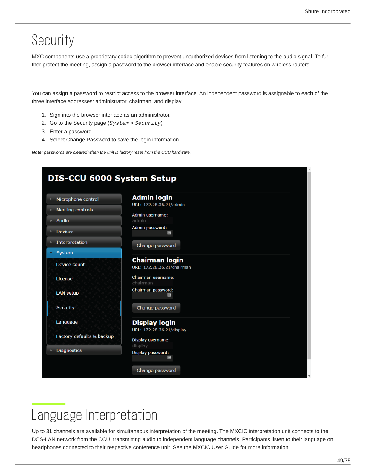
You can assign a password to restrict access to the browser interface. An independent password is assignable to each of the
three interface addresses: administrator, chairman, and display.
1.
Sign into the browser interface as an administrator.
2.
Go to the Security page (System > Security)
3.
Enter a password.
4.
Select Change Password to save the login information.
Note: passwords are cleared when the unit is factory reset from the CCU hardware.
Language Interpretation
Up to 31 channels are available for simultaneous interpretation of the meeting. The MXCIC interpretation unit connects to the
DCS-LAN network from the CCU, transmitting audio to independent language channels. Participants listen to their language on
headphones connected to their respective conference unit. See the MXCIC User Guide for more information.
49/75
Page 50
Shure Incorporated
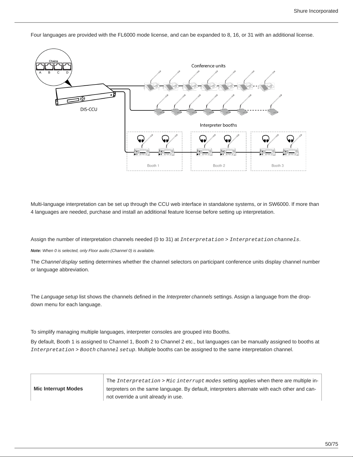
Four languages are provided with the FL6000 mode license, and can be expanded to 8, 16, or 31 with an additional license.
Interpretation Setup
Multi-language interpretation can be set up through the CCU web interface in standalone systems, or in SW6000. If more than
4 languages are needed, purchase and install an additional feature license before setting up interpretation.
Interpretation Channels
Assign the number of interpretation channels needed (0 to 31) at Interpretation > Interpretation channels.
Note: When 0 is selected, only Floor audio (Channel 0) is available.
The Channel display setting determines whether the channel selectors on participant conference units display channel number
or language abbreviation.
Language Setup
The Language setup list shows the channels defined in the Interpreter channels settings. Assign a language from the drop-
down menu for each language.
Booth Channel Setup
To simplify managing multiple languages, interpreter consoles are grouped into Booths.
By default, Booth 1 is assigned to Channel 1, Booth 2 to Channel 2 etc., but languages can be manually assigned to booths at
Interpretation > Booth channel setup. Multiple booths can be assigned to the same interpretation channel.
Interpretation Settings
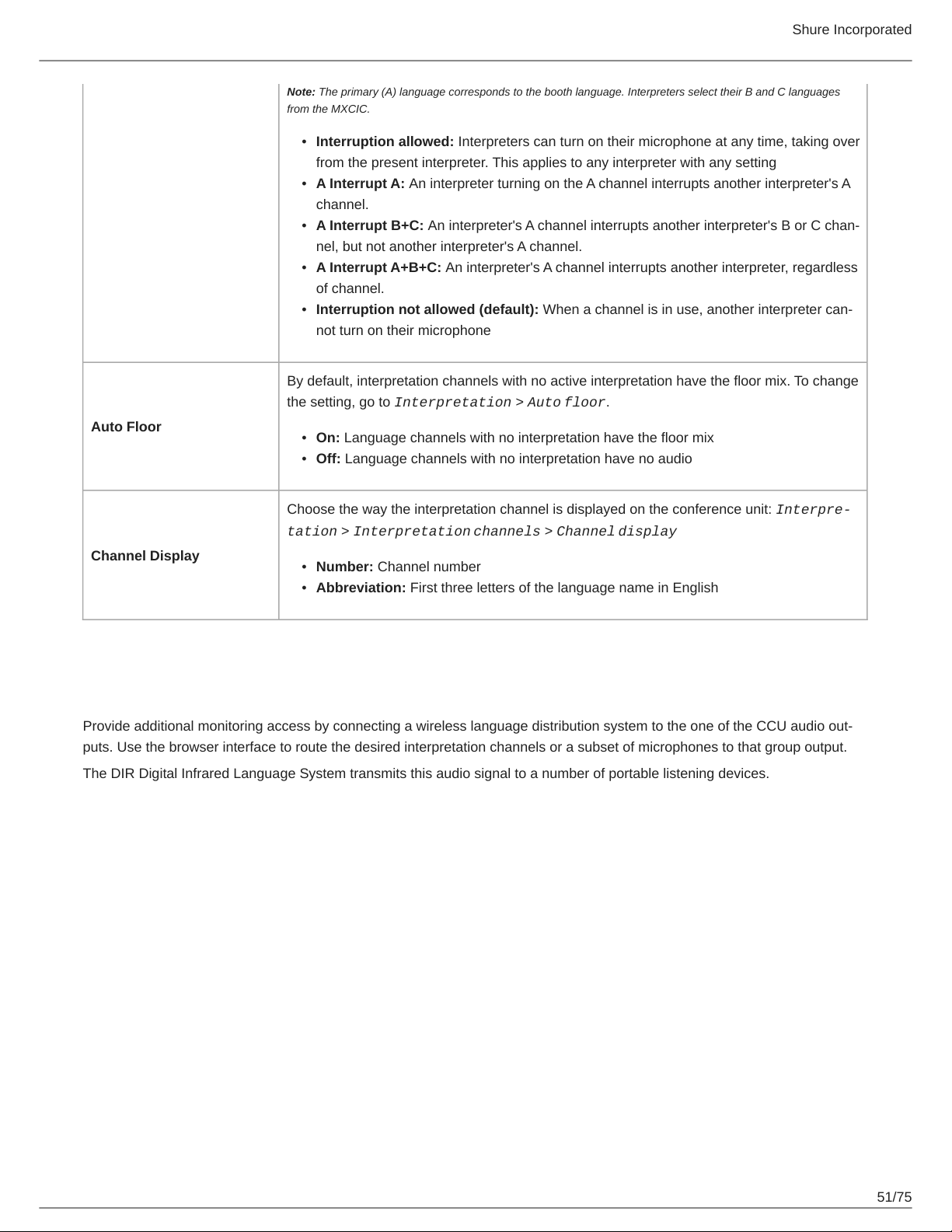
The Interpretation > Mic interrupt modes setting applies when there are multiple in-
Mic Interrupt Modes
terpreters on the same language. By default, interpreters alternate with each other and can-
not override a unit already in use.
50/75
Page 51
Auto Floor
Shure Incorporated
Note: The primary (A) language corresponds to the booth language. Interpreters select their B and C languages
from the MXCIC.
•
Interruption allowed: Interpreters can turn on their microphone at any time, taking over
from the present interpreter. This applies to any interpreter with any setting
•
A Interrupt A: An interpreter turning on the A channel interrupts another interpreter's A
channel.
•
A Interrupt B+C: An interpreter's A channel interrupts another interpreter's B or C chan-
nel, but not another interpreter's A channel.
•
A Interrupt A+B+C: An interpreter's A channel interrupts another interpreter, regardless
of channel.
•
Interruption not allowed (default): When a channel is in use, another interpreter can-
not turn on their microphone
By default, interpretation channels with no active interpretation have the floor mix. To change
the setting, go to Interpretation > Auto floor.
•
On: Language channels with no interpretation have the floor mix
•
Off: Language channels with no interpretation have no audio
Choose the way the interpretation channel is displayed on the conference unit: Interpre
tation > Interpretation channels > Channel display
Channel Display
•
Number: Channel number
•
Abbreviation: First three letters of the language name in English
Wireless Language Distribution
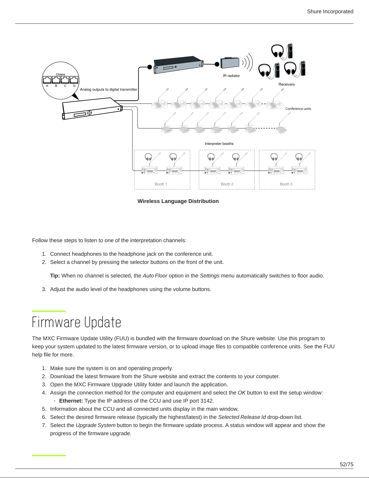
Provide additional monitoring access by connecting a wireless language distribution system to the one of the CCU audio out-
puts. Use the browser interface to route the desired interpretation channels or a subset of microphones to that group output.
The DIR Digital Infrared Language System transmits this audio signal to a number of portable listening devices.
51/75
Page 52
Shure Incorporated
Wireless Language Distribution
Listening to Interpretation
Follow these steps to listen to one of the interpretation channels:
1.
Connect headphones to the headphone jack on the conference unit.
2.
Select a channel by pressing the selector buttons on the front of the unit.
Tip: When no channel is selected, the Auto Floor option in the Settings menu automatically switches to floor audio.
3.
Adjust the audio level of the headphones using the volume buttons.
Firmware Update
The MXC Firmware Update Utility (FUU) is bundled with the firmware download on the Shure website. Use this program to
keep your system updated to the latest firmware version, or to upload image files to compatible conference units. See the FUU
help file for more.
1.
Make sure the system is on and operating properly.
2.
Download the latest firmware from the Shure website and extract the contents to your computer.
3.
Open the MXC Firmware Upgrade Utility folder and launch the application.
4.
Assign the connection method for the computer and equipment and select the OK button to exit the setup window:
◦
Ethernet: Type the IP address of the CCU and use IP port 3142.
5.
Information about the CCU and all connected units display in the main window.
6.
Select the desired firmware release (typically the highest/latest) in the Selected Release Id drop-down list.
7.
Select the Upgrade System button to begin the firmware update process. A status window will appear and show the
progress of the firmware upgrade.
52/75
Page 53
Shure Incorporated
Rackmounting the CCU
Install the central control unit in a standard 19” rack using the supplied 19” brackets. Remove the screws holding the top and
bottom covers, then attach the brackets to the front of the unit using the same screws.
Important: Use the two 10 mm length self-threading screws closest to the front and the 8 mm length threaded screw furthest
from the front.
The built-in fan draws air in on the left side and exhausts air on the right, and so does not require extra space above or below
for cooling.
Installing the Conference Units
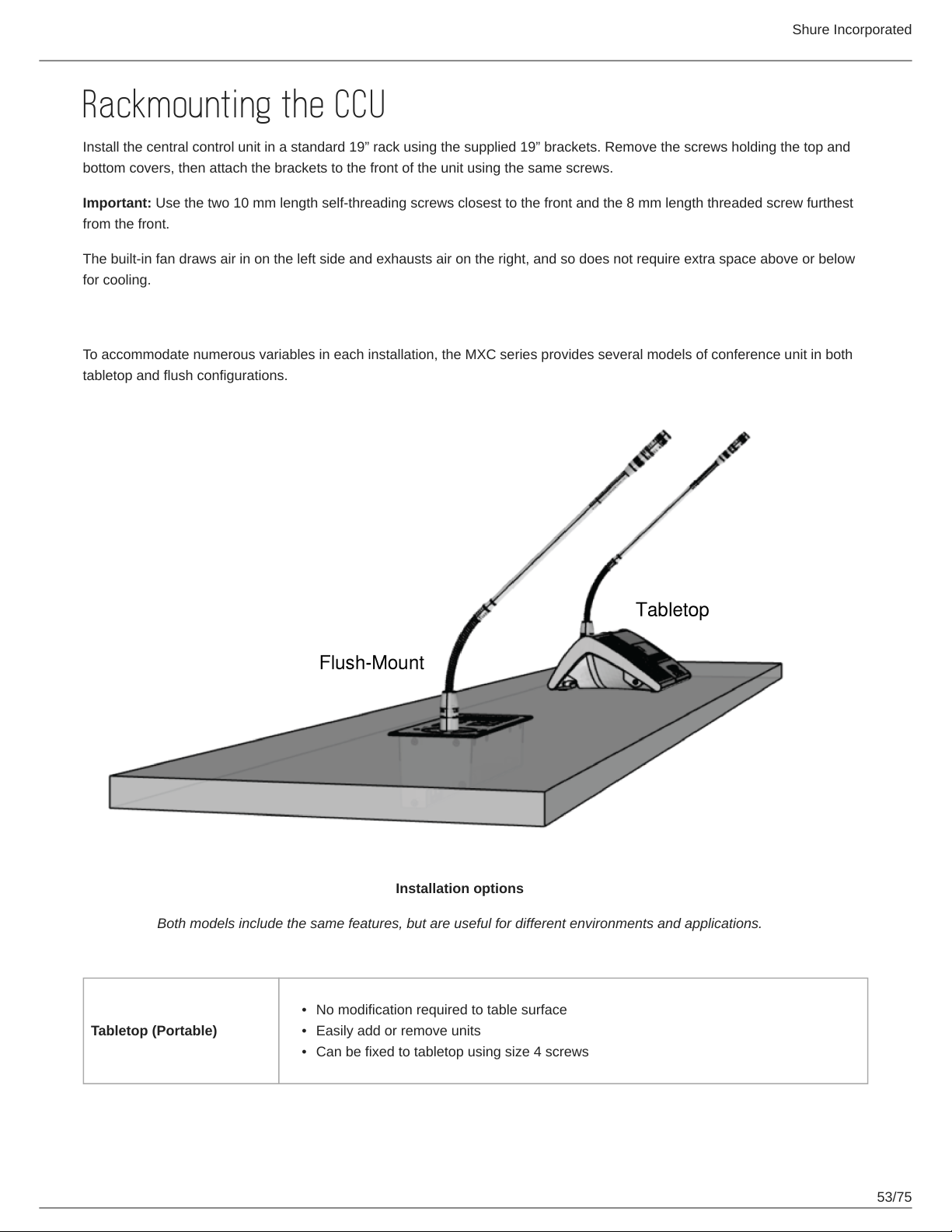
To accommodate numerous variables in each installation, the MXC series provides several models of conference unit in both
tabletop and flush configurations.
Both models include the same features, but are useful for different environments and applications.
Tabletop (Portable)
Installation options
•
No modification required to table surface
•
Easily add or remove units
•
Can be fixed to tabletop using size 4 screws
53/75
Page 54
Shure Incorporated
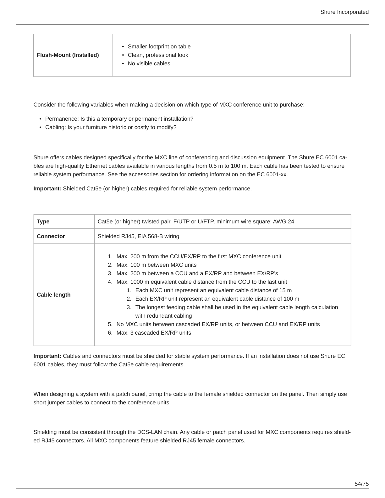
•
Smaller footprint on table
Flush-Mount (Installed)
Consider the following variables when making a decision on which type of MXC conference unit to purchase:
•
Permanence: Is this a temporary or permanent installation?
•
Cabling: Is your furniture historic or costly to modify?
•
Clean, professional look
•
No visible cables
Connecting DCS-LAN Equipment
Shure offers cables designed specifically for the MXC line of conferencing and discussion equipment. The Shure EC 6001 ca-
bles are high-quality Ethernet cables available in various lengths from 0.5 m to 100 m. Each cable has been tested to ensure
reliable system performance. See the accessories section for ordering information on the EC 6001-xx.
Important: Shielded Cat5e (or higher) cables required for reliable system performance.
Cable Requirements
Type Cat5e (or higher) twisted pair, F/UTP or U/FTP, minimum wire square: AWG 24
Connector Shielded RJ45, EIA 568-B wiring
1.
Max. 200 m from the CCU/EX/RP to the first MXC conference unit
2.
Max. 100 m between MXC units
3.
Max. 200 m between a CCU and a EX/RP and between EX/RP’s
4.
Max. 1000 m equivalent cable distance from the CCU to the last unit
1.
Cable length
5.
6.
Important: Cables and connectors must be shielded for stable system performance. If an installation does not use Shure EC
6001 cables, they must follow the Cat5e cable requirements.
Each MXC unit represent an equivalent cable distance of 15 m
2.
Each EX/RP unit represent an equivalent cable distance of 100 m
3.
The longest feeding cable shall be used in the equivalent cable length calculation
with redundant cabling
No MXC units between cascaded EX/RP units, or between CCU and EX/RP units
Max. 3 cascaded EX/RP units
Using Patch Panels
When designing a system with a patch panel, crimp the cable to the female shielded connector on the panel. Then simply use
short jumper cables to connect to the conference units.
Continuity of Shielding
Shielding must be consistent through the DCS-LAN chain. Any cable or patch panel used for MXC components requires shield-
ed RJ45 connectors. All MXC components feature shielded RJ45 female connectors.
54/75
Page 55
Shure Incorporated
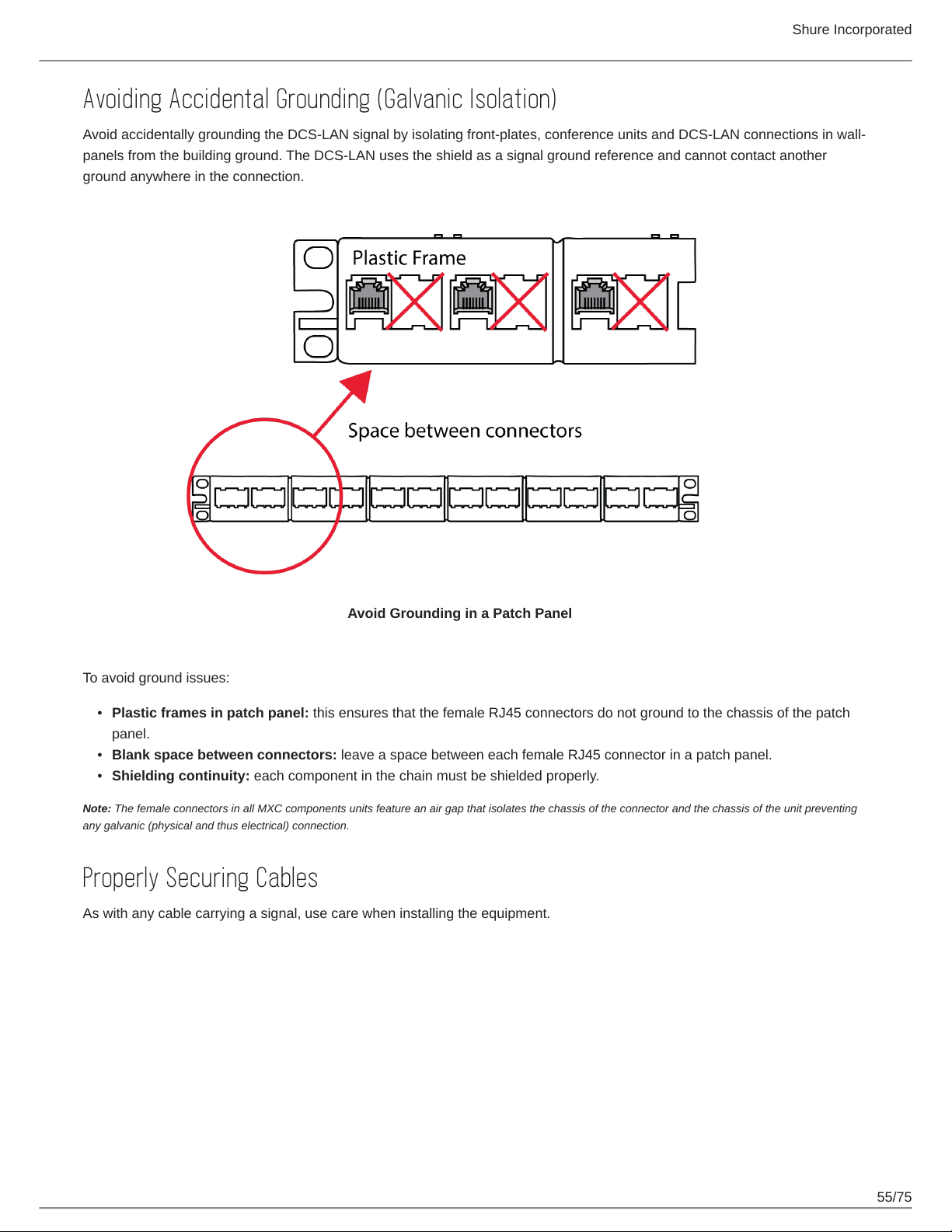
Avoiding Accidental Grounding (Galvanic Isolation)
Avoid accidentally grounding the DCS-LAN signal by isolating front-plates, conference units and DCS-LAN connections in wall-
panels from the building ground. The DCS-LAN uses the shield as a signal ground reference and cannot contact another
ground anywhere in the connection.
Avoid Grounding in a Patch Panel
To avoid ground issues:
•
Plastic frames in patch panel: this ensures that the female RJ45 connectors do not ground to the chassis of the patch
panel.
•
Blank space between connectors: leave a space between each female RJ45 connector in a patch panel.
•
Shielding continuity: each component in the chain must be shielded properly.
Note: The female connectors in all MXC components units feature an air gap that isolates the chassis of the connector and the chassis of the unit preventing
any galvanic (physical and thus electrical) connection.
Properly Securing Cables
As with any cable carrying a signal, use care when installing the equipment.
55/75
Page 56
Shure Incorporated
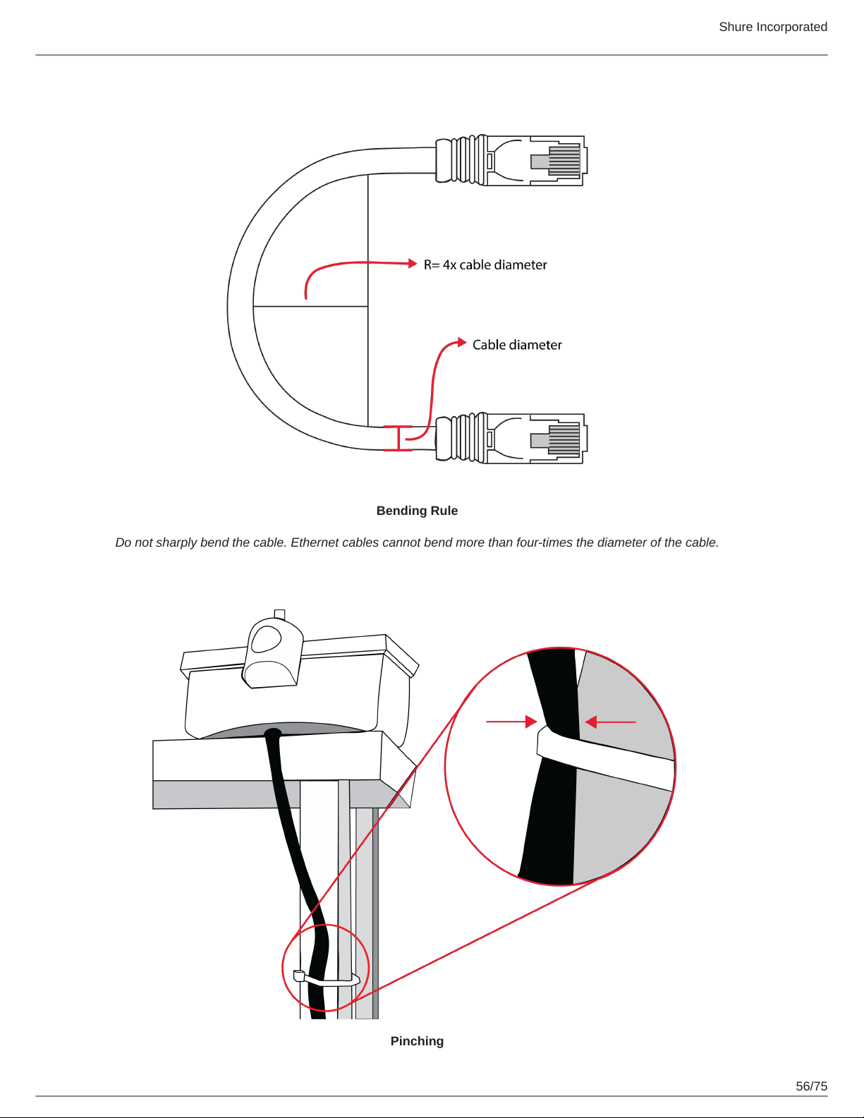
Bending Rule
Do not sharply bend the cable. Ethernet cables cannot bend more than four-times the diameter of the cable.
Pinching
56/75
Page 57
Shure Incorporated
Do not over-fasten the cable. A pinched cable may not operate correctly.
Installing Large Systems
DCS-LAN Power Calculator
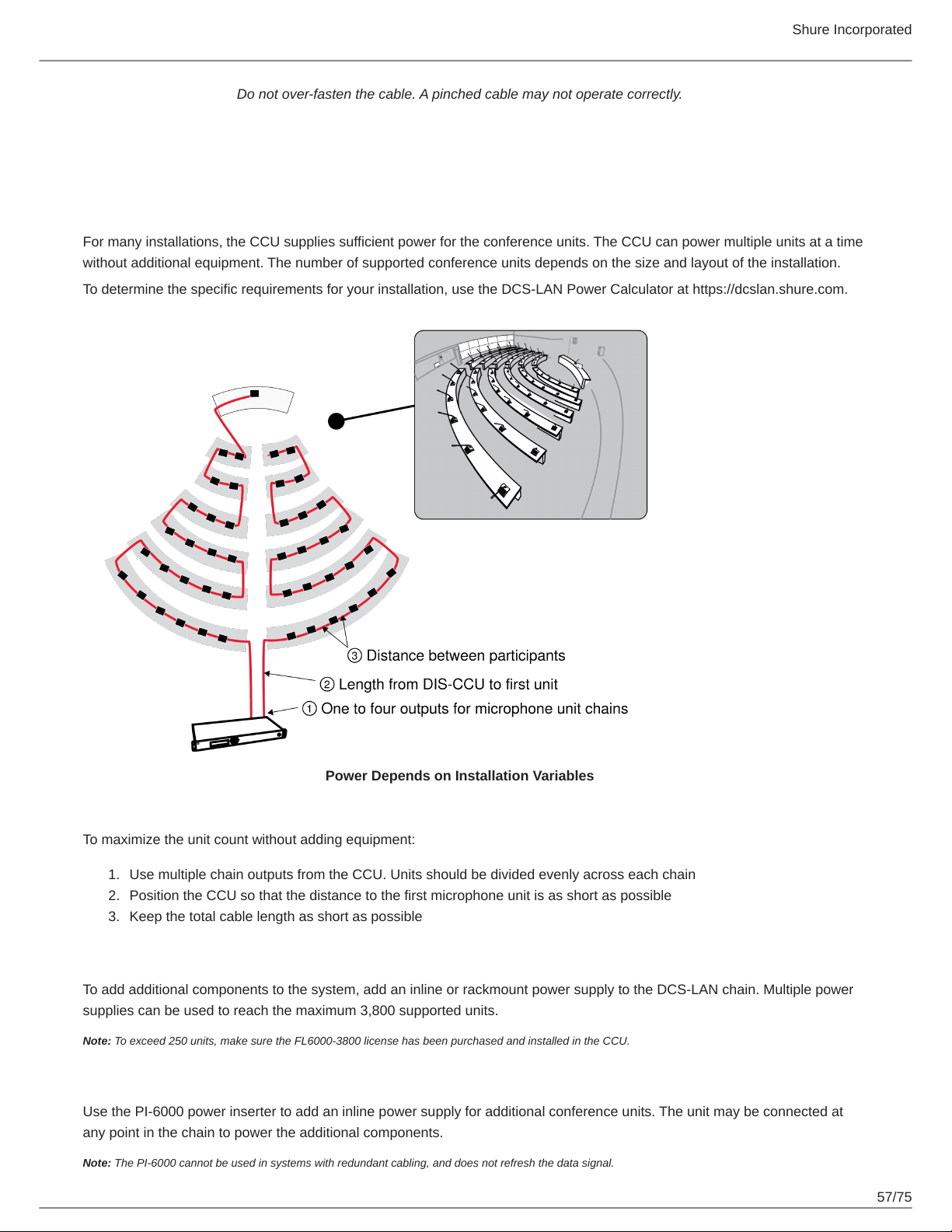
For many installations, the CCU supplies sufficient power for the conference units. The CCU can power multiple units at a time
without additional equipment. The number of supported conference units depends on the size and layout of the installation.
To determine the specific requirements for your installation, use the DCS-LAN Power Calculator at https://dcslan.shure.com.
Power Depends on Installation Variables
To maximize the unit count without adding equipment:
1.
Use multiple chain outputs from the CCU. Units should be divided evenly across each chain
2.
Position the CCU so that the distance to the first microphone unit is as short as possible
3.
Keep the total cable length as short as possible
Power Supplies for Additional Components
To add additional components to the system, add an inline or rackmount power supply to the DCS-LAN chain. Multiple power
supplies can be used to reach the maximum 3,800 supported units.
Note: To exceed 250 units, make sure the FL6000-3800 license has been purchased and installed in the CCU.
Inline Power Supply
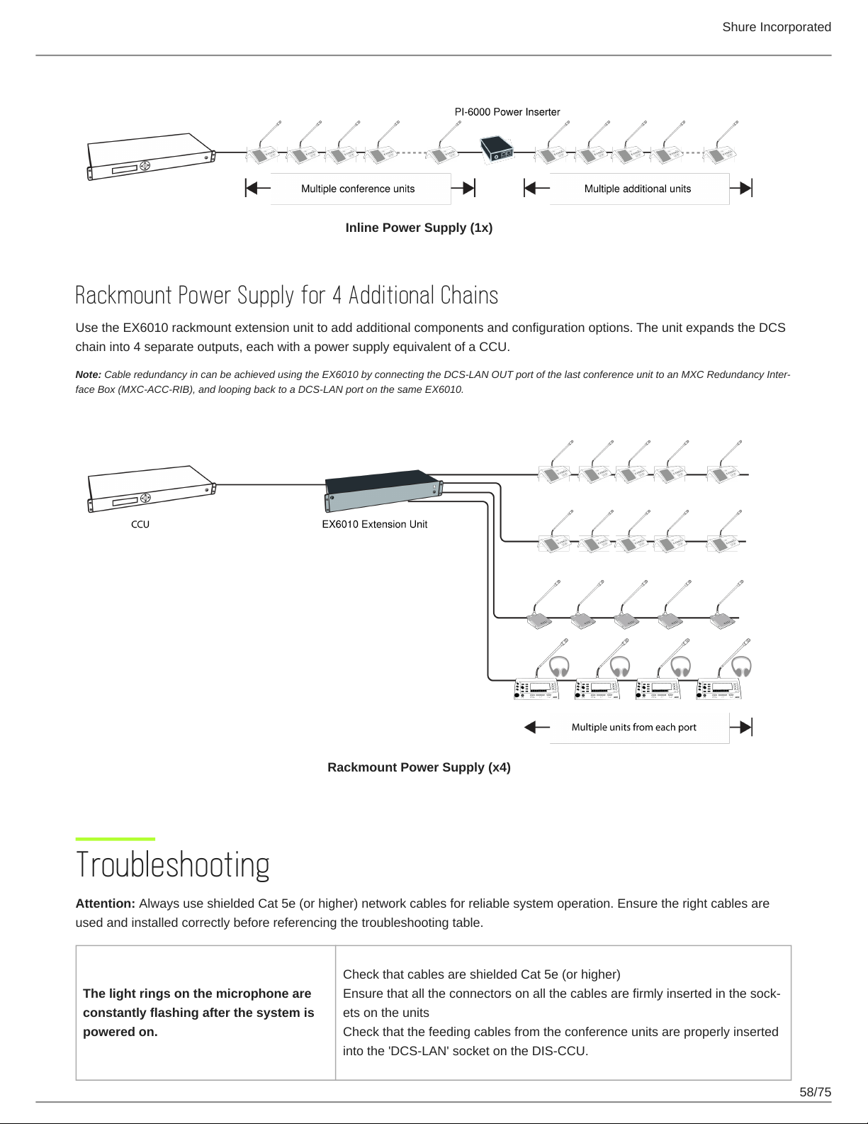
Use the PI-6000 power inserter to add an inline power supply for additional conference units. The unit may be connected at
any point in the chain to power the additional components.
Note: The PI-6000 cannot be used in systems with redundant cabling, and does not refresh the data signal.
57/75
Page 58
Shure Incorporated
Inline Power Supply (1x)
Rackmount Power Supply for 4 Additional Chains
Use the EX6010 rackmount extension unit to add additional components and configuration options. The unit expands the DCS
chain into 4 separate outputs, each with a power supply equivalent of a CCU.
Note: Cable redundancy in can be achieved using the EX6010 by connecting the DCS-LAN OUT port of the last conference unit to an MXC Redundancy Inter-
face Box (MXC-ACC-RIB), and looping back to a DCS-LAN port on the same EX6010.
Rackmount Power Supply (x4)
Troubleshooting
Attention: Always use shielded Cat 5e (or higher) network cables for reliable system operation. Ensure the right cables are
used and installed correctly before referencing the troubleshooting table.
Check that cables are shielded Cat 5e (or higher)
The light rings on the microphone are
constantly flashing after the system is
powered on.
Ensure that all the connectors on all the cables are firmly inserted in the sock-
ets on the units
Check that the feeding cables from the conference units are properly inserted
into the 'DCS-LAN' socket on the DIS-CCU.
58/75
Page 59
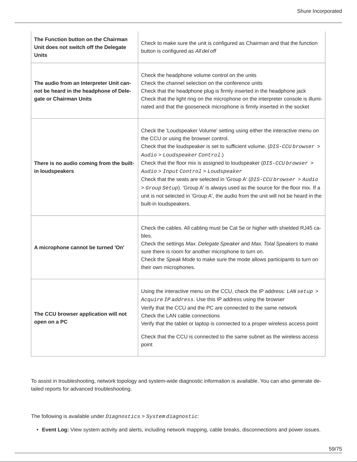
Shure Incorporated
The Function button on the Chairman
Unit does not switch off the Delegate
Units
The audio from an Interpreter Unit can-
not be heard in the headphone of Dele-
gate or Chairman Units
There is no audio coming from the built-
in loudspeakers
Check to make sure the unit is configured as Chairman and that the function
button is configured as All del off
Check the headphone volume control on the units
Check the channel selection on the conference units
Check that the headphone plug is firmly inserted in the headphone jack
Check that the light ring on the microphone on the interpreter console is illumi-
nated and that the gooseneck microphone is firmly inserted in the socket
Check the 'Loudspeaker Volume' setting using either the interactive menu on
the CCU or using the browser control.
Check that the loudspeaker is set to sufficient volume. (DIS-CCU browser >
Audio > Loudspeaker Control.)
Check that the floor mix is assigned to loudspeaker (DIS-CCU browser >
Audio > Input Control > Loudspeaker
Check that the seats are selected in 'Group A' (DIS-CCU browser > Audio
> Group Setup). 'Group A' is always used as the source for the floor mix. If a
unit is not selected in 'Group A', the audio from the unit will not be heard in the
built-in loudspeakers.
Check the cables. All cabling must be Cat 5e or higher with shielded RJ45 ca-
bles.
A microphone cannot be turned 'On'
The CCU browser application will not
open on a PC
Check the settings Max. Delegate Speaker and Max. Total Speakers to make
sure there is room for another microphone to turn on.
Check the Speak Mode to make sure the mode allows participants to turn on
their own microphones.
Using the interactive menu on the CCU, check the IP address: LAN setup >
Acquire IP address. Use this IP address using the browser
Verify that the CCU and the PC are connected to the same network
Check the LAN cable connections
Verify that the tablet or laptop is connected to a proper wireless access point
Check that the CCU is connected to the same subnet as the wireless access
point
Diagnostics
To assist in troubleshooting, network topology and system-wide diagnostic information is available. You can also generate de-
tailed reports for advanced troubleshooting.
System Diagnostic
The following is available under Diagnostics > System diagnostic:
•
Event Log: View system activity and alerts, including network mapping, cable breaks, disconnections and power issues.
59/75
Page 60
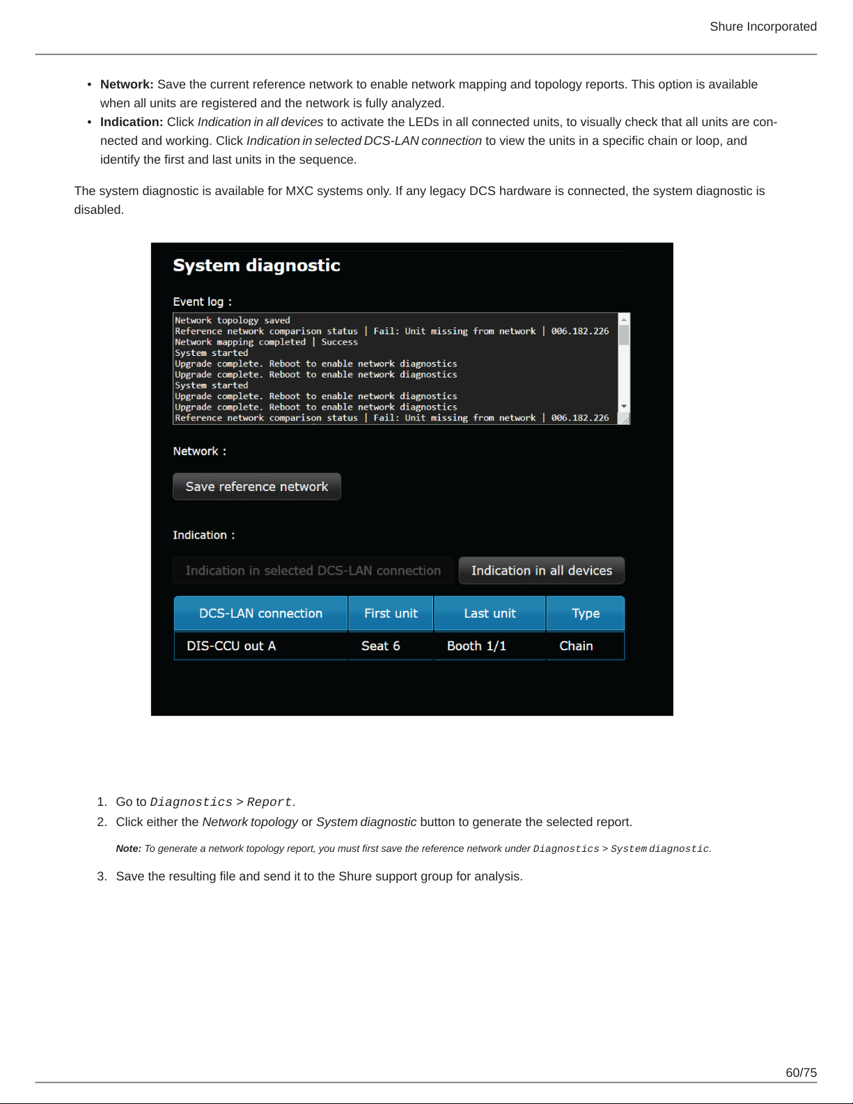
Shure Incorporated
•
Network: Save the current reference network to enable network mapping and topology reports. This option is available
when all units are registered and the network is fully analyzed.
•
Indication: Click Indication in all devices to activate the LEDs in all connected units, to visually check that all units are con-
nected and working. Click Indication in selected DCS-LAN connection to view the units in a specific chain or loop, and
identify the first and last units in the sequence.
The system diagnostic is available for MXC systems only. If any legacy DCS hardware is connected, the system diagnostic is
disabled.
Report
1.
2.
3.
Go to Diagnostics > Report.
Click either the Network topology or System diagnostic button to generate the selected report.
Note: To generate a network topology report, you must first save the reference network under Diagnostics > System diagnostic.
Save the resulting file and send it to the Shure support group for analysis.
60/75
Page 61
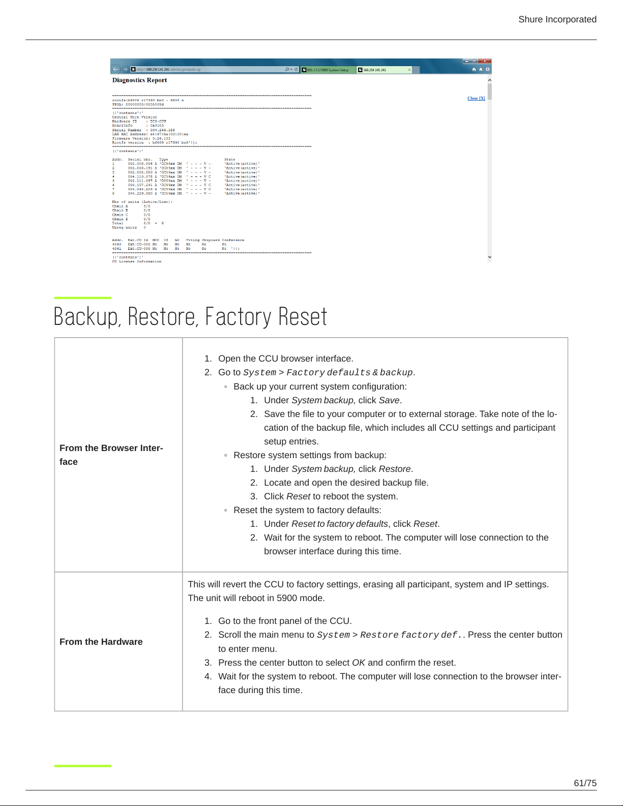
Shure Incorporated
Backup, Restore, Factory Reset
1.
Open the CCU browser interface.
2.
Go to System > Factory defaults & backup.
◦
Back up your current system configuration:
1.
Under System backup, click Save.
2.
Save the file to your computer or to external storage. Take note of the lo-
cation of the backup file, which includes all CCU settings and participant
From the Browser Inter-
face
◦
Restore system settings from backup:
◦
Reset the system to factory defaults:
This will revert the CCU to factory settings, erasing all participant, system and IP settings.
The unit will reboot in 5900 mode.
setup entries.
1.
Under System backup, click Restore.
2.
Locate and open the desired backup file.
3.
Click Reset to reboot the system.
1.
Under Reset to factory defaults, click Reset.
2.
Wait for the system to reboot. The computer will lose connection to the
browser interface during this time.
From the Hardware
1.
Go to the front panel of the CCU.
2.
Scroll the main menu to System > Restore factory def.. Press the center button
to enter menu.
3.
Press the center button to select OK and confirm the reset.
4.
Wait for the system to reboot. The computer will lose connection to the browser inter-
face during this time.
61/75
Page 62
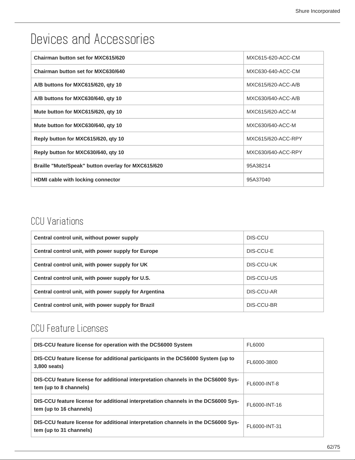
Devices and Accessories
Chairman button set for MXC615/620 MXC615-620-ACC-CM
Chairman button set for MXC630/640 MXC630-640-ACC-CM
A/B buttons for MXC615/620, qty 10 MXC615/620-ACC-A/B
A/B buttons for MXC630/640, qty 10 MXC630/640-ACC-A/B
Mute button for MXC615/620, qty 10 MXC615/620-ACC-M
Mute button for MXC630/640, qty 10 MXC630/640-ACC-M
Reply button for MXC615/620, qty 10 MXC615/620-ACC-RPY
Reply button for MXC630/640, qty 10 MXC630/640-ACC-RPY
Braille "Mute/Speak" button overlay for MXC615/620 95A38214
Shure Incorporated
HDMI cable with locking connector 95A37040
Model Variations
CCU Variations
Central control unit, without power supply DIS-CCU
Central control unit, with power supply for Europe DIS-CCU-E
Central control unit, with power supply for UK DIS-CCU-UK
Central control unit, with power supply for U.S. DIS-CCU-US
Central control unit, with power supply for Argentina DIS-CCU-AR
Central control unit, with power supply for Brazil DIS-CCU-BR
CCU Feature Licenses
DIS-CCU feature license for operation with the DCS6000 System FL6000
DIS-CCU feature license for additional participants in the DCS6000 System (up to
3,800 seats)
DIS-CCU feature license for additional interpretation channels in the DCS6000 Sys-
tem (up to 8 channels)
DIS-CCU feature license for additional interpretation channels in the DCS6000 Sys-
tem (up to 16 channels)
DIS-CCU feature license for additional interpretation channels in the DCS6000 Sys-
tem (up to 31 channels)
FL6000-3800
FL6000-INT-8
FL6000-INT-16
FL6000-INT-31
62/75
Page 63
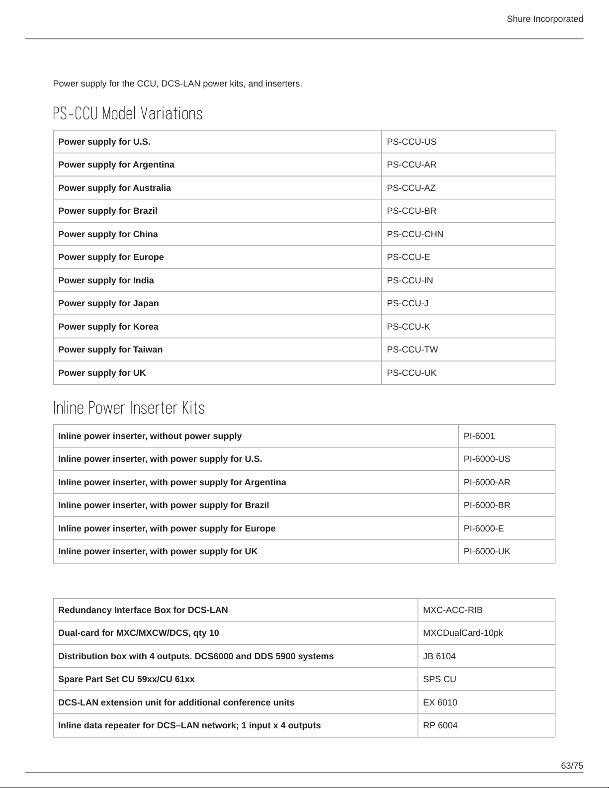
PS-CCU Power Supply
Power supply for the CCU, DCS-LAN power kits, and inserters.
PS-CCU Model Variations
Power supply for U.S. PS-CCU-US
Power supply for Argentina PS-CCU-AR
Power supply for Australia PS-CCU-AZ
Power supply for Brazil PS-CCU-BR
Power supply for China PS-CCU-CHN
Power supply for Europe PS-CCU-E
Power supply for India PS-CCU-IN
Power supply for Japan PS-CCU-J
Shure Incorporated
Power supply for Korea PS-CCU-K
Power supply for Taiwan PS-CCU-TW
Power supply for UK PS-CCU-UK
Inline Power Inserter Kits
Inline power inserter, without power supply PI-6001
Inline power inserter, with power supply for U.S. PI-6000-US
Inline power inserter, with power supply for Argentina PI-6000-AR
Inline power inserter, with power supply for Brazil PI-6000-BR
Inline power inserter, with power supply for Europe PI-6000-E
Inline power inserter, with power supply for UK PI-6000-UK
Optional Accessories and Replacement Parts
Redundancy Interface Box for DCS-LAN MXC-ACC-RIB
Dual-card for MXC/MXCW/DCS, qty 10 MXCDualCard-10pk
Distribution box with 4 outputs. DCS6000 and DDS 5900 systems JB 6104
Spare Part Set CU 59xx/CU 61xx SPS CU
DCS-LAN extension unit for additional conference units EX 6010
Inline data repeater for DCS–LAN network; 1 input x 4 outputs RP 6004
63/75
Page 64
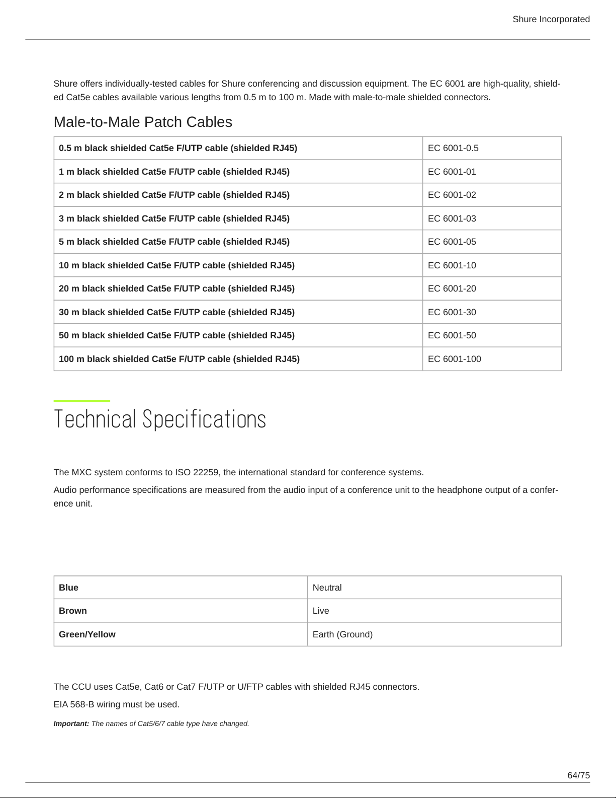
Shure Incorporated
Pre-Tested Shure Cables
Shure offers individually-tested cables for Shure conferencing and discussion equipment. The EC 6001 are high-quality, shield-
ed Cat5e cables available various lengths from 0.5 m to 100 m. Made with male-to-male shielded connectors.
Male-to-Male Patch Cables
0.5 m black shielded Cat5e F/UTP cable (shielded RJ45) EC 6001-0.5
1 m black shielded Cat5e F/UTP cable (shielded RJ45) EC 6001-01
2 m black shielded Cat5e F/UTP cable (shielded RJ45) EC 6001-02
3 m black shielded Cat5e F/UTP cable (shielded RJ45) EC 6001-03
5 m black shielded Cat5e F/UTP cable (shielded RJ45) EC 6001-05
10 m black shielded Cat5e F/UTP cable (shielded RJ45) EC 6001-10
20 m black shielded Cat5e F/UTP cable (shielded RJ45) EC 6001-20
30 m black shielded Cat5e F/UTP cable (shielded RJ45) EC 6001-30
50 m black shielded Cat5e F/UTP cable (shielded RJ45) EC 6001-50
100 m black shielded Cat5e F/UTP cable (shielded RJ45) EC 6001-100
Technical Specifications
Microflex Complete System
The MXC system conforms to ISO 22259, the international standard for conference systems.
Audio performance specifications are measured from the audio input of a conference unit to the headphone output of a confer-
ence unit.
Wiring Details
Connection to Main Power Supply
Blue Neutral
Brown Live
Green/Yellow Earth (Ground)
DCS-LAN Chain
The CCU uses Cat5e, Cat6 or Cat7 F/UTP or U/FTP cables with shielded RJ45 connectors.
EIA 568-B wiring must be used.
Important: The names of Cat5/6/7 cable type have changed.
64/75
Page 65
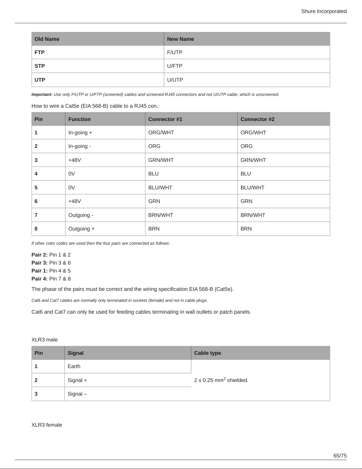
Old Name New Name
FTP F/UTP
STP U/FTP
UTP U/UTP
Important: Use only F/UTP or U/FTP (screened) cables and screened RJ45 connectors and not U/UTP cable, which is unscreened.
How to wire a Cat5e (EIA 568-B) cable to a RJ45 con.:
Pin Function Connector #1 Connector #2
1 In-going + ORG/WHT ORG/WHT
2 In-going - ORG ORG
3 +48V GRN/WHT GRN/WHT
4 0V BLU BLU
Shure Incorporated
5 0V BLU/WHT BLU/WHT
6 +48V GRN GRN
7 Outgoing - BRN/WHT BRN/WHT
8 Outgoing + BRN BRN
If other color codes are used then the four pairs are connected as follows:
Pair 2: Pin 1 & 2
Pair 3: Pin 3 & 6
Pair 1: Pin 4 & 5
Pair 4: Pin 7 & 8
The phase of the pairs must be correct and the wiring specification EIA 568-B (Cat5e).
Cat6 and Cat7 cables are normally only terminated in sockets (female) and not in cable plugs.
Cat6 and Cat7 can only be used for feeding cables terminating in wall outlets or patch panels.
Analog Audio Out
XLR3 male
Pin Signal Cable type
1 Earth
3 Signal –
Analog Audio In
XLR3 female
2 x 0.25 mm shielded.2 Signal +
2
65/75
Page 66
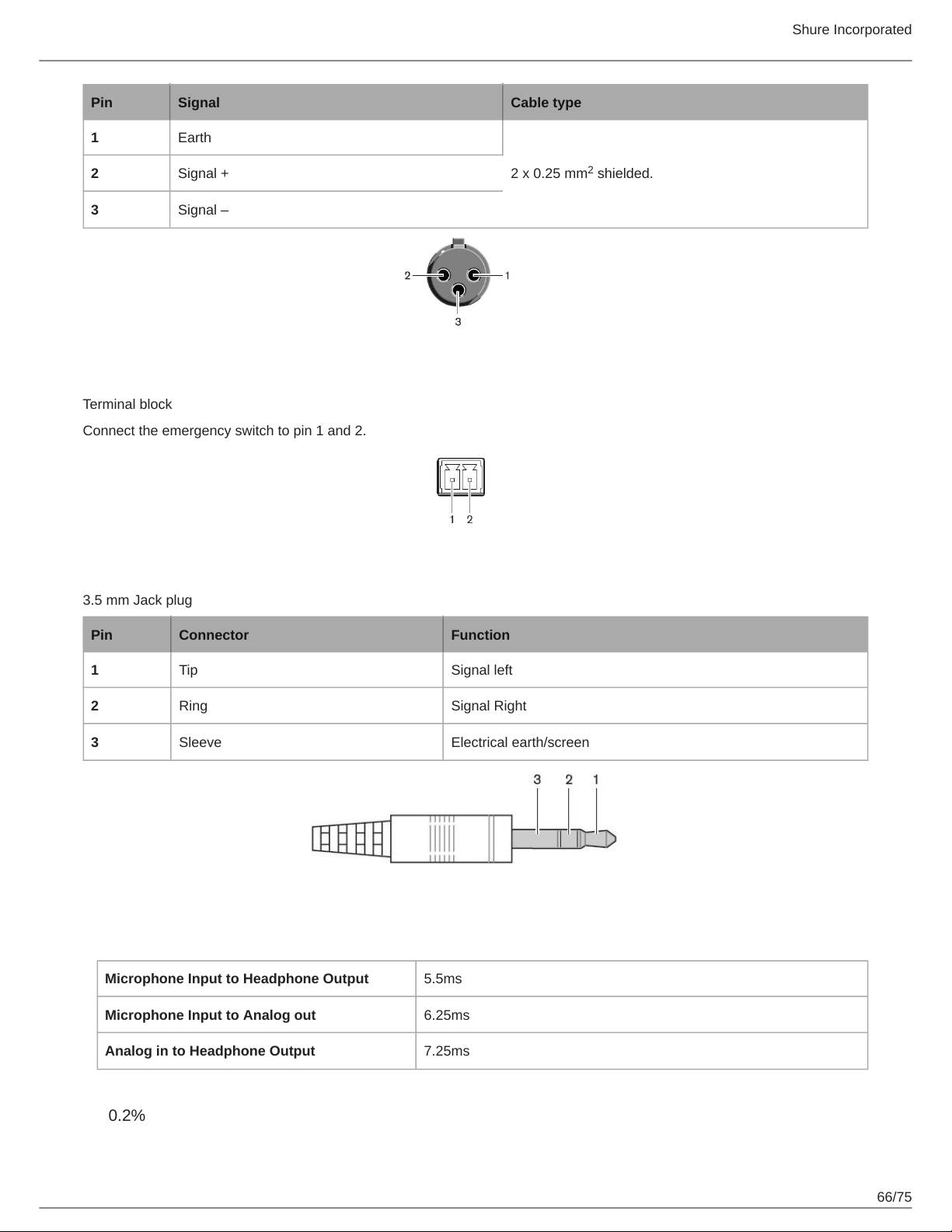
Pin Signal Cable type
1 Earth
Shure Incorporated
3 Signal –
Emergency Switch
Terminal block
Connect the emergency switch to pin 1 and 2.
Earphones
3.5 mm Jack plug
2 x 0.25 mm shielded.2 Signal +
2
Pin Connector Function
1 Tip Signal left
2 Ring Signal Right
3 Sleeve Electrical earth/screen
Common System Specifications
Latency
Microphone Input to Headphone Output 5.5ms
Microphone Input to Analog out 6.25ms
Analog in to Headphone Output 7.25ms
THD+N
0.2%
66/75
Page 67
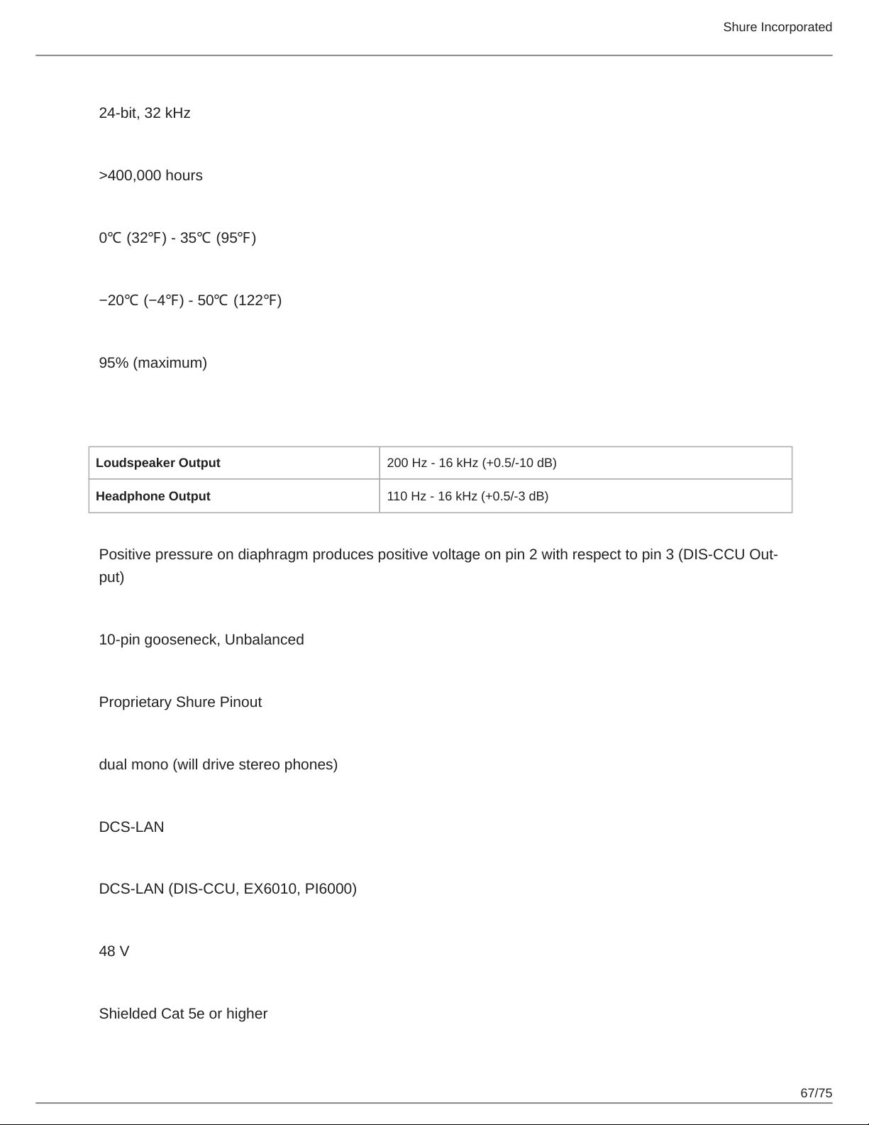
Digital Signal Processing
24-bit, 32 kHz
Mean Time Between Failures
>400,000 hours
Operating Temperature Range
0℃ (32℉) - 35℃ (95℉)
Storage Temperature Range
−20℃ (−4℉) - 50℃ (122℉)
Relative Humidity
95% (maximum)
Conference Unit Specifications
Audio Frequency Response
Shure Incorporated
Loudspeaker Output 200 Hz - 16 kHz (+0.5/-10 dB)
Headphone Output 110 Hz - 16 kHz (+0.5/-3 dB)
Polarity
Positive pressure on diaphragm produces positive voltage on pin 2 with respect to pin 3 (DIS-CCU Out-
put)
Microphone Connector
10-pin gooseneck, Unbalanced
Pin Assignments
Proprietary Shure Pinout
Headphone Output
dual mono (will drive stereo phones)
Network Connections
DCS-LAN
Power Supply
DCS-LAN (DIS-CCU, EX6010, PI6000)
Voltage At Source
48 V
Cable Requirements
Shielded Cat 5e or higher
67/75
Page 68
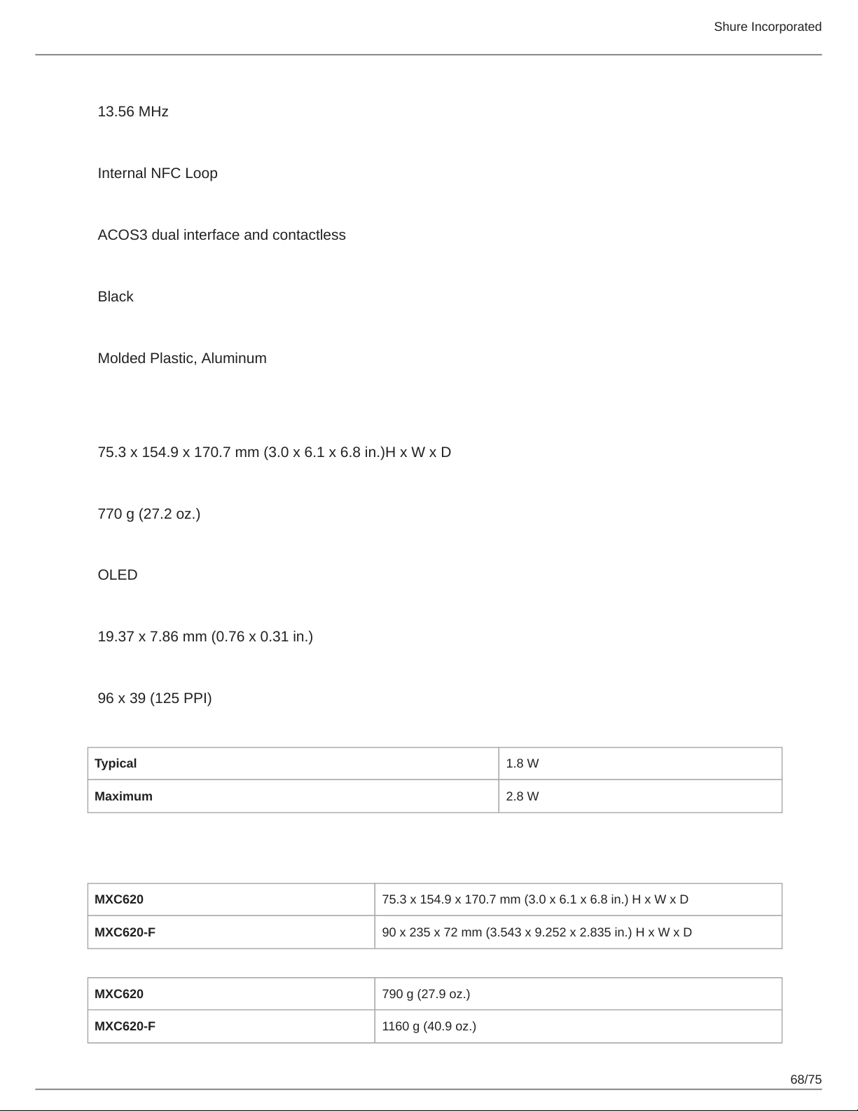
NFC Carrier Frequency
13.56 MHz
Antenna Type
Internal NFC Loop
NFC Card Compatibility
ACOS3 dual interface and contactless
Color
Black
Housing
Molded Plastic, Aluminum
MXC615
Dimensions
75.3 x 154.9 x 170.7 mm (3.0 x 6.1 x 6.8 in.)H x W x D
Shure Incorporated
Weight
770 g (27.2 oz.)
Screen Type
OLED
Screen Size
19.37 x 7.86 mm (0.76 x 0.31 in.)
Display Resolution
96 x 39 (125 PPI)
Power Consumption
Typical 1.8 W
Maximum 2.8 W
MXC620 / MXC620-F
Dimensions
MXC620 75.3 x 154.9 x 170.7 mm (3.0 x 6.1 x 6.8 in.) H x W x D
MXC620-F 90 x 235 x 72 mm (3.543 x 9.252 x 2.835 in.) H x W x D
Weight
MXC620 790 g (27.9 oz.)
MXC620-F 1160 g (40.9 oz.)
68/75
Page 69
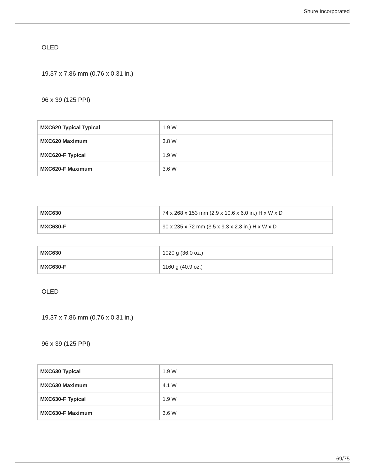
Screen Type
OLED
Screen Size
19.37 x 7.86 mm (0.76 x 0.31 in.)
Display Resolution
96 x 39 (125 PPI)
Power Consumption
MXC620 Typical Typical 1.9 W
MXC620 Maximum 3.8 W
MXC620-F Typical 1.9 W
MXC620-F Maximum 3.6 W
Shure Incorporated
MXC630 / MXC630-F
Dimensions
MXC630 74 x 268 x 153 mm (2.9 x 10.6 x 6.0 in.) H x W x D
MXC630-F 90 x 235 x 72 mm (3.5 x 9.3 x 2.8 in.) H x W x D
Weight
MXC630 1020 g (36.0 oz.)
MXC630-F 1160 g (40.9 oz.)
Screen Type
OLED
Screen Size
19.37 x 7.86 mm (0.76 x 0.31 in.)
Display Resolution
96 x 39 (125 PPI)
Power Consumption
MXC630 Typical 1.9 W
MXC630 Maximum 4.1 W
MXC630-F Typical 1.9 W
MXC630-F Maximum 3.6 W
69/75
Page 70
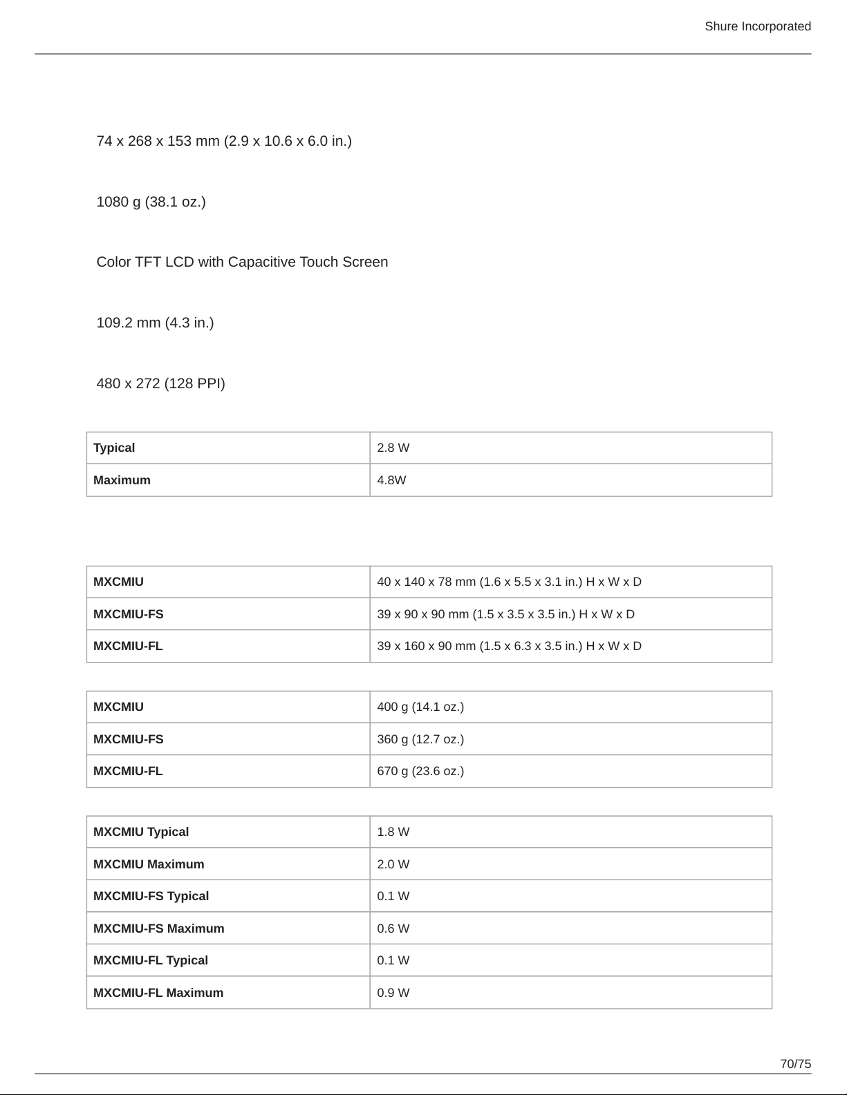
MXC640
Dimensions
74 x 268 x 153 mm (2.9 x 10.6 x 6.0 in.)
Weight
1080 g (38.1 oz.)
Screen Type
Color TFT LCD with Capacitive Touch Screen
Screen Size
109.2 mm (4.3 in.)
Display Resolution
480 x 272 (128 PPI)
Power Consumption
Shure Incorporated
Typical 2.8 W
Maximum 4.8W
MXCMIU
Dimensions
MXCMIU 40 x 140 x 78 mm (1.6 x 5.5 x 3.1 in.) H x W x D
MXCMIU-FS 39 x 90 x 90 mm (1.5 x 3.5 x 3.5 in.) H x W x D
MXCMIU-FL 39 x 160 x 90 mm (1.5 x 6.3 x 3.5 in.) H x W x D
Weight
MXCMIU 400 g (14.1 oz.)
MXCMIU-FS 360 g (12.7 oz.)
MXCMIU-FL 670 g (23.6 oz.)
Power Consumption
MXCMIU Typical 1.8 W
MXCMIU Maximum 2.0 W
MXCMIU-FS Typical 0.1 W
MXCMIU-FS Maximum 0.6 W
MXCMIU-FL Typical 0.1 W
MXCMIU-FL Maximum 0.9 W
70/75
Page 71
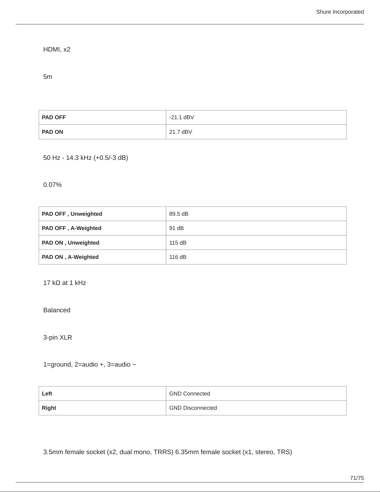
MXCMIU Connection to MXCMIU-FS / MXCMIU-FL
HDMI, x2
Maximum Cable Length
5m
XLR Input
Maximum Input Level
PAD OFF -21.1 dBV
PAD ON 21.7 dBV
Audio Frequency Response
50 Hz - 14.3 kHz (+0.5/-3 dB)
THD+N
0.07%
Shure Incorporated
Dynamic Range
PAD OFF , Unweighted 89.5 dB
PAD OFF , A-Weighted 91 dB
PAD ON , Unweighted 115 dB
PAD ON , A-Weighted 116 dB
Input Impedance
17 kΩ at 1 kHz
Configuration
Balanced
Type
3-pin XLR
Pin Assignments
1=ground, 2=audio +, 3=audio −
GND Lift
Left GND Connected
Right GND Disconnected
MXCIC
Audio Output Type
3.5mm female socket (x2, dual mono, TRRS) 6.35mm female socket (x1, stereo, TRS)
71/75
Page 72
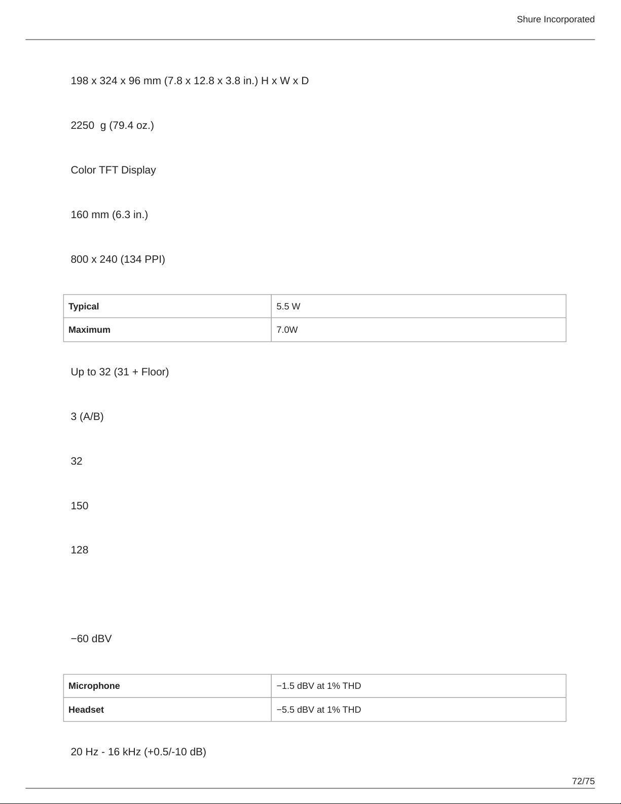
Dimensions
198 x 324 x 96 mm (7.8 x 12.8 x 3.8 in.) H x W x D
Weight
2250 g (79.4 oz.)
Screen Type
Color TFT Display
Screen Size
160 mm (6.3 in.)
Display Resolution
800 x 240 (134 PPI)
Power Consumption
Typical 5.5 W
Shure Incorporated
Maximum 7.0W
Number of Incoming Channels
Up to 32 (31 + Floor)
Number of Outgoing Channels
3 (A/B)
Maximum Units Per Booth
32
Maximum Number of Booths
150
Maximum Number of Units (total)
128
Audio Specifications
Audio Input
Nominal Input Level
−60 dBV
Maximum Audio Input Level
Microphone −1.5 dBV at 1% THD
Headset −5.5 dBV at 1% THD
Audio Frequency Response
20 Hz - 16 kHz (+0.5/-10 dB)
72/75
Page 73
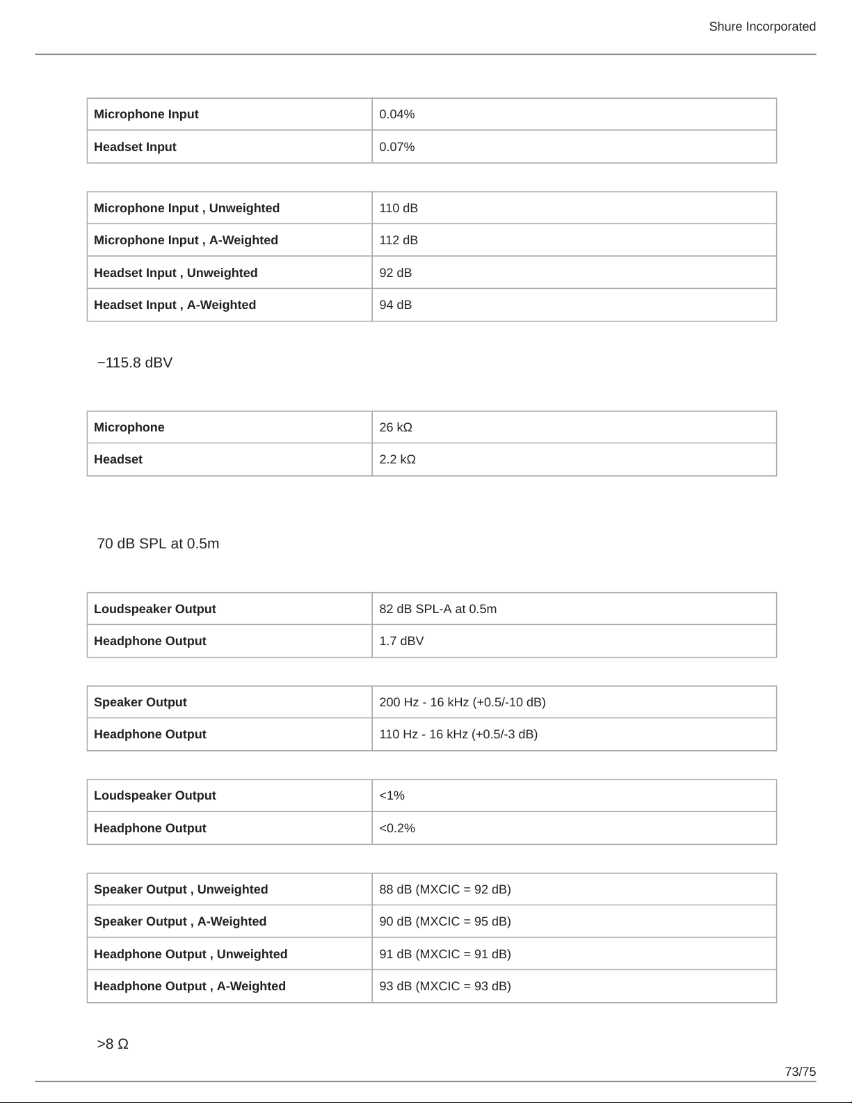
THD+N
Microphone Input 0.04%
Headset Input 0.07%
Dynamic Range
Microphone Input , Unweighted 110 dB
Microphone Input , A-Weighted 112 dB
Headset Input , Unweighted 92 dB
Headset Input , A-Weighted 94 dB
Preamplifier Equivalent Input Noise (EIN)
−115.8 dBV
Input Impedance
Microphone 26 kΩ
Shure Incorporated
Headset 2.2 kΩ
Audio Output
Nominal Output Level
70 dB SPL at 0.5m
Maximum Audio Output Level
Loudspeaker Output 82 dB SPL-A at 0.5m
Headphone Output 1.7 dBV
Audio Frequency Response
Speaker Output 200 Hz - 16 kHz (+0.5/-10 dB)
Headphone Output 110 Hz - 16 kHz (+0.5/-3 dB)
THD+N
Loudspeaker Output <1%
Headphone Output <0.2%
Dynamic Range
Speaker Output , Unweighted 88 dB (MXCIC = 92 dB)
Speaker Output , A-Weighted 90 dB (MXCIC = 95 dB)
Headphone Output , Unweighted 91 dB (MXCIC = 91 dB)
Headphone Output , A-Weighted 93 dB (MXCIC = 93 dB)
Load Impedance
>8 Ω
73/75
Page 74
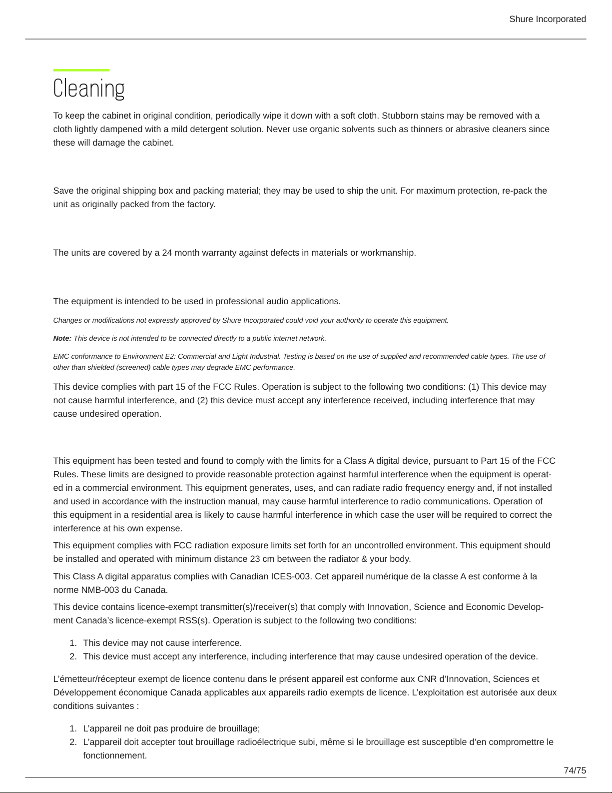
Shure Incorporated
Cleaning
To keep the cabinet in original condition, periodically wipe it down with a soft cloth. Stubborn stains may be removed with a
cloth lightly dampened with a mild detergent solution. Never use organic solvents such as thinners or abrasive cleaners since
these will damage the cabinet.
Repacking
Save the original shipping box and packing material; they may be used to ship the unit. For maximum protection, re-pack the
unit as originally packed from the factory.
Warranty
The units are covered by a 24 month warranty against defects in materials or workmanship.
Important Product Information
The equipment is intended to be used in professional audio applications.
Changes or modifications not expressly approved by Shure Incorporated could void your authority to operate this equipment.
Note: This device is not intended to be connected directly to a public internet network.
EMC conformance to Environment E2: Commercial and Light Industrial. Testing is based on the use of supplied and recommended cable types. The use of
other than shielded (screened) cable types may degrade EMC performance.
This device complies with part 15 of the FCC Rules. Operation is subject to the following two conditions: (1) This device may
not cause harmful interference, and (2) this device must accept any interference received, including interference that may
cause undesired operation.
Information to the user
This equipment has been tested and found to comply with the limits for a Class A digital device, pursuant to Part 15 of the FCC
Rules. These limits are designed to provide reasonable protection against harmful interference when the equipment is operat-
ed in a commercial environment. This equipment generates, uses, and can radiate radio frequency energy and, if not installed
and used in accordance with the instruction manual, may cause harmful interference to radio communications. Operation of
this equipment in a residential area is likely to cause harmful interference in which case the user will be required to correct the
interference at his own expense.
This equipment complies with FCC radiation exposure limits set forth for an uncontrolled environment. This equipment should
be installed and operated with minimum distance 23 cm between the radiator & your body.
This Class A digital apparatus complies with Canadian ICES-003. Cet appareil numérique de la classe A est conforme à la
norme NMB-003 du Canada.
This device contains licence-exempt transmitter(s)/receiver(s) that comply with Innovation, Science and Economic Develop-
ment Canada’s licence-exempt RSS(s). Operation is subject to the following two conditions:
1.
This device may not cause interference.
2.
This device must accept any interference, including interference that may cause undesired operation of the device.
L’émetteur/récepteur exempt de licence contenu dans le présent appareil est conforme aux CNR d’Innovation, Sciences et
Développement économique Canada applicables aux appareils radio exempts de licence. L’exploitation est autorisée aux deux
conditions suivantes :
1.
L’appareil ne doit pas produire de brouillage;
2.
L’appareil doit accepter tout brouillage radioélectrique subi, même si le brouillage est susceptible d’en compromettre le
fonctionnement.
74/75
Page 75
Shure Incorporated
Certifications
This product meets the Essential Requirements of all relevant European directives and is eligible for CE marking.
EAC Clarification: This product meets Russian compliance regulations as well as EAC marking requirements.
Hereby, Shure Incorporated declares that the radio equipment is in compliance with Directive 2014/53/EU. The full text of the
EU declaration of conformity is available at the following internet address: http://www.shure.com/europe/compliance
Authorized European representative:
Shure Europe GmbH
Headquarters Europe, Middle East & Africa
Department: EMEA Approval
Jakob-Dieffenbacher-Str. 12
75031 Eppingen, Germany
Phone: +49-7262-92 49 0
Fax: +49-7262-92 49 11 4
Email: [email protected]
75/75
 Loading...