

Shure MXCMIU, MXC615, MXC620, MXC630, MXC640 User Manual
...
MXC
®
Microflex Complete
User guide for the Shure Microflex Complete audio conferencing system.
Version: 2 (2019-I)

Table of Contents
MXCMicroflex® Complete 4
Important Safeguards 4
Labels 5
Note for Power Connections 5
Power Disconnect 6
Warning: 6
Overview 6
Information in This Manual 6
Features 6
Feature Licenses 7
DIS-CCU Central Control Unit 9
Simplified Audio Diagram 10
CCU Hardware Description 10
Menu Navigation 11
MXC Conference Units 13
Conference Unit Hardware Descriptions 13
Portable Model Variations 14
Flush-Mounted Model Variations 16
NFC Card functionality 18
Microflex Multipin Gooseneck Microphones 18
Snap-Fit Windscreen 19
Connecting Conference Units and DCS-LAN Compo-
nents 20
Connection Diagrams 21
Basic Setup with Conference Units 21
Controlling the Conference Unit 23
Chairman Role 24
Delegate Role 24
Shure Incorporated
Dual Delegate Role 24
User Indications 25
Web Interface 25
Open the CCU Web Interface 26
Assigning the Network Address 27
Additional Screens 27
Language Setting 30
User Interface for the MXC640 31
Navigation Pane 32
Home Screen 33
Agenda 34
Voting/Result Menu 35
Results 35
Channel Selector 36
Voting Functionality 37
Audio Settings 37
Microphone Functionality 37
Route Microphones to Groups 38
Floor Mix on the Loudspeakers 39
Headphone Channels 39
Analog Audio Outputs 40
Adding an External Audio Source 40
Meeting Configuration 41
Names, Roles and Seat Numbers 42
Meeting Controls 43
Voice Detection 47
Security 48
Password Protect the Browser Interface 49
Language Interpretation 49
Interpretation Setup 50
2/75

Shure Incorporated
Interpretation Settings 50
Wireless Language Distribution 51
Listening to Interpretation 52
Firmware Update 52
Rackmounting the CCU 52
Installing the Conference Units 53
Connecting DCS-LAN Equipment 54
Installing Large Systems 57
Troubleshooting 58
Diagnostics 59
Backup, Restore, Factory Reset 61
Devices and Accessories 61
Model Variations 62
PS-CCU Power Supply 63
Optional Accessories and Replacement Parts 63
Technical Specifications 64
Microflex Complete System 64
Wiring Details 64
Common System Specifications 66
Conference Unit Specifications 67
Audio Specifications 72
Cleaning 74
Repacking 74
Warranty 74
Important Product Information 74
Certifications 75
3/75
MXC
Microflex Complete
®
Important Safeguards
1.
Read these instructions - All the safety and operating instructions should be read before the apparatus or system is
operated.
2.
Keep these instructions - The important safety instructions and operating instructions should be retained for future
reference.
3.
Follow all warnings - All warnings on the apparatus and in the operating instructions should be adhered to.
4.
Follow all instructions - All instructions for installation or use/operating should be followed.
5.
Do not use this apparatus near water - Do not use this apparatus in a water or moistures environment - for example,
near a bath tub, wash bowl, kitchen sink, or laundry tub, in a wet basement, near a swimming pool, in an unprotected
outdoor installation, or any area which is classified as a wet location.
6.
Warning: To reduce the risk of fire or electric shock, do not expose this apparatus to rain or moisture and no
objects filled with liquids, such as vases, should be placed on this apparatus.
7.
Clean only with dry cloth - Unplug the apparatus from the outlet before cleaning. Do not use liquid cleaners or aerosol
cleaners.
8.
Do not block any ventilation openings. Install in accordance with the manufacturer’s instructions - Openings in
the enclosure, if any, are provided for ventilation and to ensure reliable operation of the apparatus and to protect it from
overheating. These openings must not be blocked or covered. This apparatus should not be placed in a built-in installa-
tion unless proper ventilation is provided or the manufacturer’s instructions have been adhered to.
9.
Do not install near any heat sources such as radiators, heat registers, stoves, air ducts, or other apparatus (in-
cluding amplifiers) that produce heat.
10.
Do not install the unit in a place exposed to direct sunlight, excessive dust or humidity, mechanical vibration or
shock .
11.
To avoid moisture condensations do not install the unit where the temperature may rise rapidly.
12.
Do not defeat the safety purpose of the polarized or ground-type plug. A polarized plug has two blades with one
wider than the other. A grounding type plug has two blades and a third grounding prong. The wider blade or the third
prong is provided for your safety. If the provided plug does not fit into your outlet, consult an electrician for replacement
of the obsolete outlet.
13.
Protect the power cord from being walked on or pinched particularly at plug, convenience receptacles, and the
point where they exit from the apparatus.
14.
Only use attachments/accessories specified by the manufacturer . Any mounting of the apparatus should follow
the manufacturer’s instructions, and should use a mounting accessory recommended by the manufacturer.
15.
Use only with the cart, stand, tripod, bracket or table specified by the manufacturer, or sold with the apparatus.
Shure Incorporated
When a cart is used, use caution when moving the cart/apparatus combination to avoid in-
jury from tip-over - Quick stops, excessive force, and uneven surfaces may cause the appli-
ance and cart combination to overturn.
16.
Unplug this apparatus during lighting storms or when unused for long periods of time . – Not applicable when
special functions are to be maintained, such as evacuation systems.
4/75
Shure Incorporated
17.
Refer all servicing to qualified service personnel. Servicing is required when the apparatus has been damaged
in any way, such as power-supply cord or plug is damaged, liquid has been spilled or objects have fallen into
the apparatus, the apparatus has been exposed to rain or moisture, does not operate normally, or has been
dropped.
18.
Replacement Parts - When replacement parts are required, be sure the service technician has used replacement parts
specified by the manufacturer or having the same characteristics as the original part.
Unauthorized substitutions may result in fire, electric shock or other hazards.
19.
Safety Check - Upon completion of any service or repairs to this apparatus, ask the service technician to perform safe-
ty checks to determine that the apparatus is in proper operating condition.
20.
Overloading - Do not overload outlets and extension cords as this can result in a risk of fire or electric shock.
21.
Power Sources - This apparatus should be operated only from the type of power source indicated on the marking la-
bel. If you are not sure of the type of power supply you plan to use, consult your appliance dealer or local power com-
pany. For apparatuses intended to operate from battery power, or other sources, refer to the operating instructions.
22.
Power Lines - An outdoor system should not be located in the vicinity of overhead power lines or other electric light or
power circuits, or where it can fall into such power lines or circuits. When installing an outdoor system, extreme care
should be taken to keep from touching such power lines or circuits, as contact with them might be fatal.
23.
Object and Liquid Entry - Never push objects of any kind into this apparatus through openings as they may touch
dangerous voltage points or short-out parts that could result in a fire or electric shock.
Never spill liquid of any kind on the apparatus. Should any liquid or solid object fall into the cabinet, unplug the unit and
have it checked by qualified personnel before operating it further.
Labels
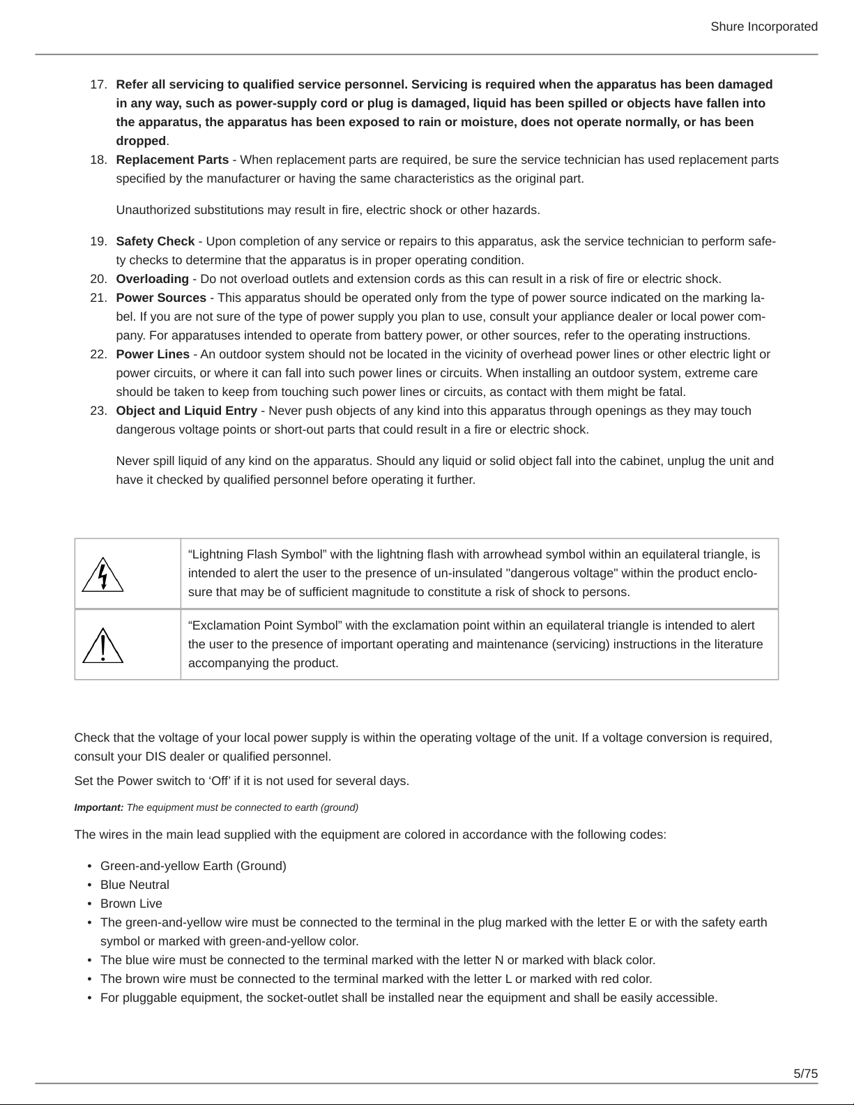
“Lightning Flash Symbol” with the lightning flash with arrowhead symbol within an equilateral triangle, is
intended to alert the user to the presence of un-insulated "dangerous voltage" within the product enclo-
sure that may be of sufficient magnitude to constitute a risk of shock to persons.
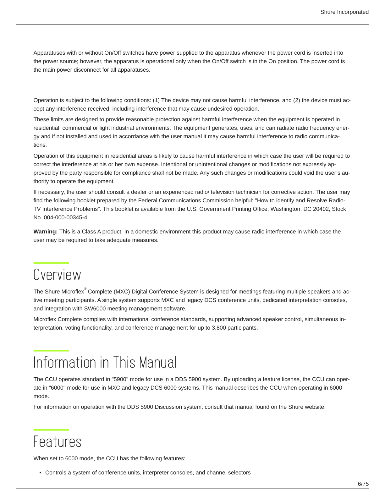
“Exclamation Point Symbol” with the exclamation point within an equilateral triangle is intended to alert
the user to the presence of important operating and maintenance (servicing) instructions in the literature
accompanying the product.
Note for Power Connections
Check that the voltage of your local power supply is within the operating voltage of the unit. If a voltage conversion is required,
consult your DIS dealer or qualified personnel.
Set the Power switch to ‘Off’ if it is not used for several days.
Important: The equipment must be connected to earth (ground)
The wires in the main lead supplied with the equipment are colored in accordance with the following codes:
•
Green-and-yellow Earth (Ground)
•
Blue Neutral
•
Brown Live
•
The green-and-yellow wire must be connected to the terminal in the plug marked with the letter E or with the safety earth
symbol or marked with green-and-yellow color.
•
The blue wire must be connected to the terminal marked with the letter N or marked with black color.
•
The brown wire must be connected to the terminal marked with the letter L or marked with red color.
•
For pluggable equipment, the socket-outlet shall be installed near the equipment and shall be easily accessible.
5/75
Shure Incorporated
Power Disconnect
Apparatuses with or without On/Off switches have power supplied to the apparatus whenever the power cord is inserted into
the power source; however, the apparatus is operational only when the On/Off switch is in the On position. The power cord is
the main power disconnect for all apparatuses.
Warning:
Operation is subject to the following conditions: (1) The device may not cause harmful interference, and (2) the device must ac-
cept any interference received, including interference that may cause undesired operation.
These limits are designed to provide reasonable protection against harmful interference when the equipment is operated in
residential, commercial or light industrial environments. The equipment generates, uses, and can radiate radio frequency ener-
gy and if not installed and used in accordance with the user manual it may cause harmful interference to radio communica-
tions.
Operation of this equipment in residential areas is likely to cause harmful interference in which case the user will be required to
correct the interference at his or her own expense. Intentional or unintentional changes or modifications not expressly ap-
proved by the party responsible for compliance shall not be made. Any such changes or modifications could void the user’s au-
thority to operate the equipment.
If necessary, the user should consult a dealer or an experienced radio/ television technician for corrective action. The user may
find the following booklet prepared by the Federal Communications Commission helpful: "How to identify and Resolve Radio-
TV Interference Problems". This booklet is available from the U.S. Government Printing Office, Washington, DC 20402, Stock
No. 004-000-00345-4.
Warning: This is a Class A product. In a domestic environment this product may cause radio interference in which case the
user may be required to take adequate measures.
Overview
The Shure Microflex Complete (MXC) Digital Conference System is designed for meetings featuring multiple speakers and ac-
tive meeting participants. A single system supports MXC and legacy DCS conference units, dedicated interpretation consoles,
and integration with SW6000 meeting management software.
Microflex Complete complies with international conference standards, supporting advanced speaker control, simultaneous in-
terpretation, voting functionality, and conference management for up to 3,800 participants.
®
Information in This Manual
The CCU operates standard in "5900" mode for use in a DDS 5900 system. By uploading a feature license, the CCU can oper-
ate in "6000" mode for use in MXC and legacy DCS 6000 systems. This manual describes the CCU when operating in 6000
mode.
For information on operation with the DDS 5900 Discussion system, consult that manual found on the Shure website.
Features
When set to 6000 mode, the CCU has the following features:
•
Controls a system of conference units, interpreter consoles, and channel selectors
6/75
Shure Incorporated
•
Transports secure audio signal with a proprietary codec algorithm
•
Provides a web server for advanced control through a browser interface
•
Supplies power to the units in the system
•
Supports up to 31 interpretation channels for multilingual meetings
•
Provides eight audio outputs to send interpretation channels or microphone groups to PA systems, audio mixers, audio
recorders, or a language distribution system
•
Provides two audio inputs for connecting wireless microphones, processed audio signals, an emergency broadcast mes-
sage (EEM), or music during meeting breaks
•
One rack unit (1RU) size installs into a standard 19" rack
Feature Licenses
The CCU operates with DDS 5900, legacy DCS 6000, and MXC conference systems. The CCU includes the DDS 5900 mode
as standard, and can operate in 6000 mode after installing a feature license.
To use MXC or DCS 6000 conference units, ensure the FL6000 is installed and operating on the CCU.
Purchasing the Feature License File
Contact your regional Shure sales representative to purchase a feature license file to enable 6000 mode and expansion fea-
tures. The features are bundled in a single .xml file generated specifically for the serial number of the CCU.
Adding the License to the CCU
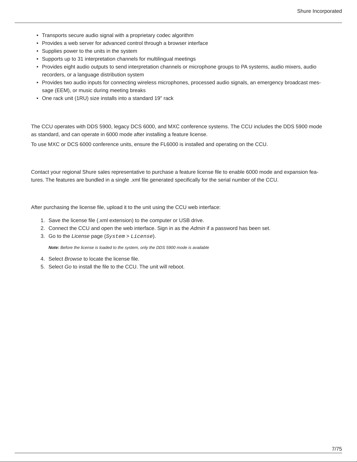
After purchasing the license file, upload it to the unit using the CCU web interface:
1.
Save the license file (.xml extension) to the computer or USB drive.
2.
Connect the CCU and open the web interface. Sign in as the Admin if a password has been set.
3.
Go to the License page (System > License).
Note: Before the license is loaded to the system, only the DDS 5900 mode is available
4.
Select Browse to locate the license file.
5.
Select Go to install the file to the CCU. The unit will reboot.
7/75
Shure Incorporated
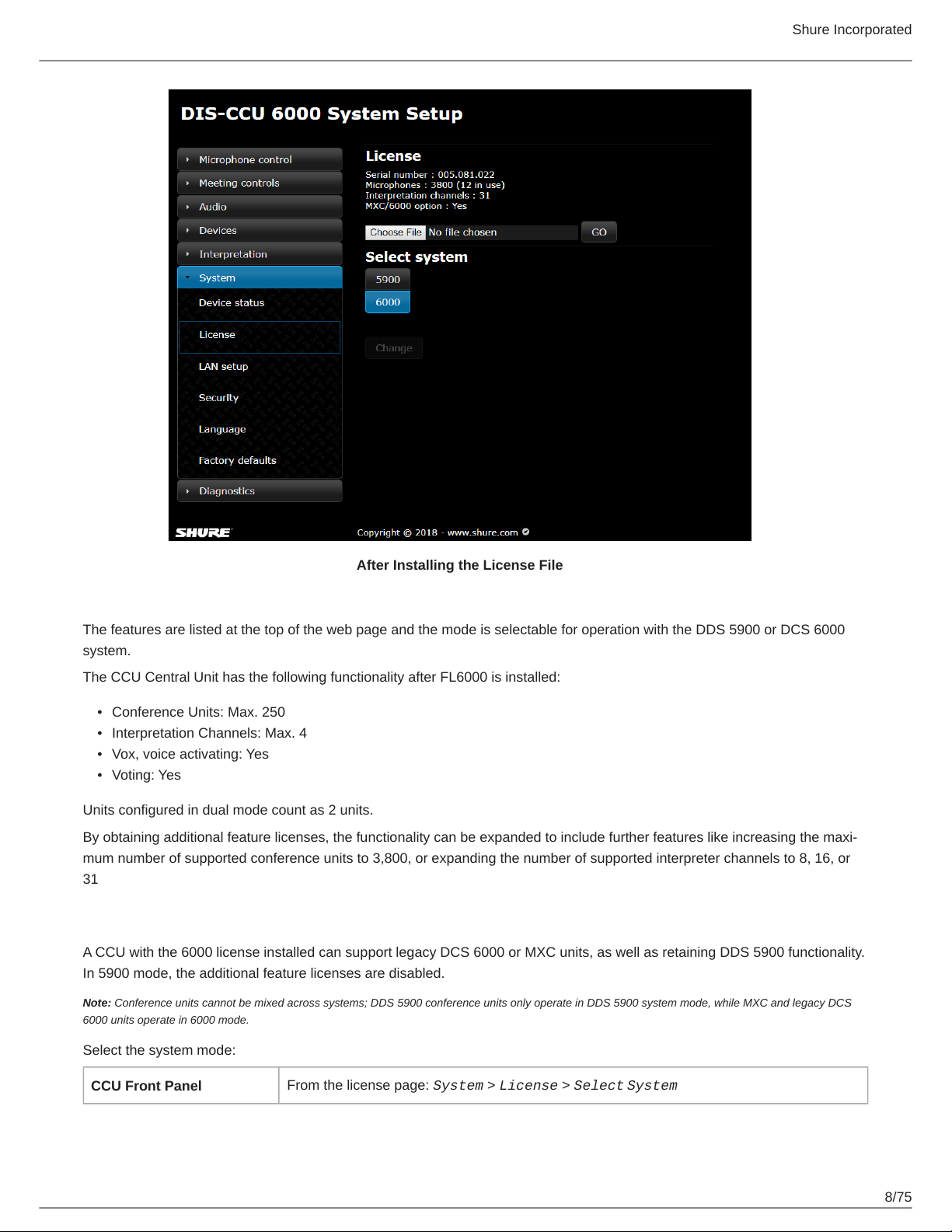
After Installing the License File
The features are listed at the top of the web page and the mode is selectable for operation with the DDS 5900 or DCS 6000
system.
The CCU Central Unit has the following functionality after FL6000 is installed:
•
Conference Units: Max. 250
•
Interpretation Channels: Max. 4
•
Vox, voice activating: Yes
•
Voting: Yes
Units configured in dual mode count as 2 units.
By obtaining additional feature licenses, the functionality can be expanded to include further features like increasing the maxi-
mum number of supported conference units to 3,800, or expanding the number of supported interpreter channels to 8, 16, or
31
Select the System Mode
A CCU with the 6000 license installed can support legacy DCS 6000 or MXC units, as well as retaining DDS 5900 functionality.
In 5900 mode, the additional feature licenses are disabled.
Note: Conference units cannot be mixed across systems; DDS 5900 conference units only operate in DDS 5900 system mode, while MXC and legacy DCS
6000 units operate in 6000 mode.
Select the system mode:
CCU Front Panel
From the license page: System > License > Select System
8/75
Shure Incorporated
Web Interface
System > License Info > Select [5900 or 6000] System
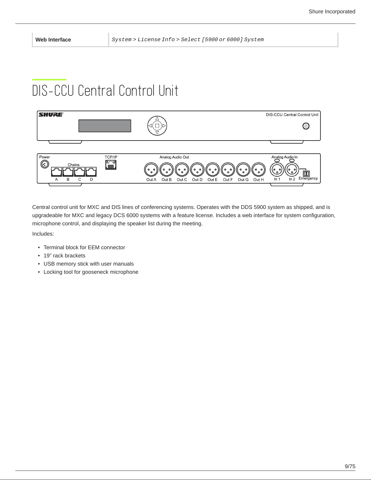
DIS-CCU Central Control Unit
Central control unit for MXC and DIS lines of conferencing systems. Operates with the DDS 5900 system as shipped, and is
upgradeable for MXC and legacy DCS 6000 systems with a feature license. Includes a web interface for system configuration,
microphone control, and displaying the speaker list during the meeting.
Includes:
•
Terminal block for EEM connector
•
19” rack brackets
•
USB memory stick with user manuals
•
Locking tool for gooseneck microphone
9/75

Simplified Audio Diagram
Shure Incorporated
CCU Hardware Description
10/75
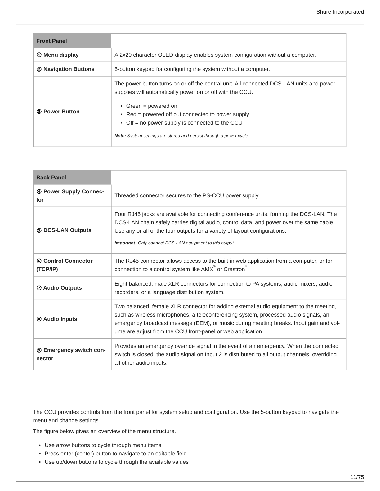
Front Panel
① Menu display A 2x20 character OLED-display enables system configuration without a computer.
② Navigation Buttons 5-button keypad for configuring the system without a computer.
The power button turns on or off the central unit. All connected DCS-LAN units and power
supplies will automatically power on or off with the CCU.
•
③ Power Button
Back Panel
Green = powered on
•
Red = powered off but connected to power supply
•
Off = no power supply is connected to the CCU
Note: System settings are stored and persist through a power cycle.
Shure Incorporated
④ Power Supply Connec-
tor
⑤ DCS-LAN Outputs
⑥ Control Connector
(TCP/IP)
⑦ Audio Outputs
⑧ Audio Inputs
⑨ Emergency switch con-
nector
Threaded connector secures to the PS-CCU power supply.
Four RJ45 jacks are available for connecting conference units, forming the DCS-LAN. The
DCS-LAN chain safely carries digital audio, control data, and power over the same cable.
Use any or all of the four outputs for a variety of layout configurations.
Important: Only connect DCS-LAN equipment to this output.
The RJ45 connector allows access to the built-in web application from a computer, or for
connection to a control system like AMX or Crestron .
Eight balanced, male XLR connectors for connection to PA systems, audio mixers, audio
recorders, or a language distribution system.
Two balanced, female XLR connector for adding external audio equipment to the meeting,
such as wireless microphones, a teleconferencing system, processed audio signals, an
emergency broadcast message (EEM), or music during meeting breaks. Input gain and vol-
ume are adjust from the CCU front-panel or web application.
Provides an emergency override signal in the event of an emergency. When the connected
switch is closed, the audio signal on Input 2 is distributed to all output channels, overriding
all other audio inputs.
® ®
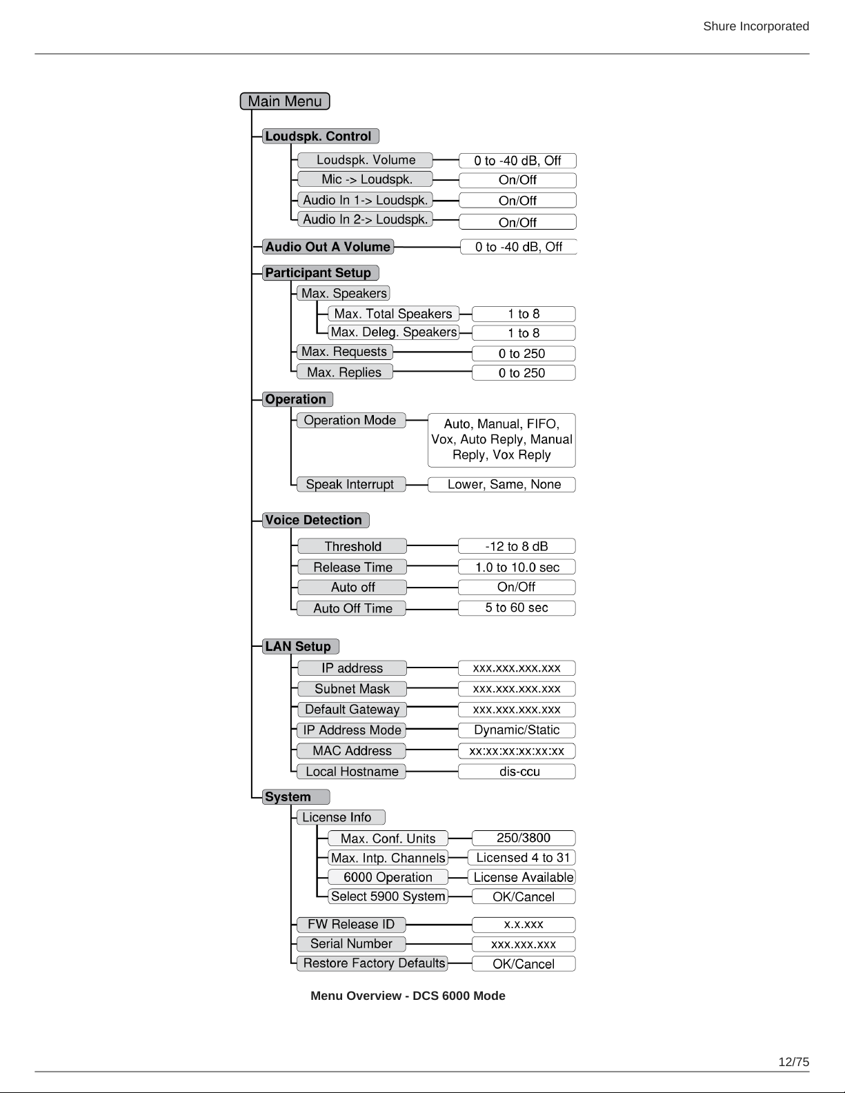
Menu Navigation
The CCU provides controls from the front panel for system setup and configuration. Use the 5-button keypad to navigate the
menu and change settings.
The figure below gives an overview of the menu structure.
•
Use arrow buttons to cycle through menu items
•
Press enter (center) button to navigate to an editable field.
•
Use up/down buttons to cycle through the available values
11/75
Shure Incorporated
Menu Overview - DCS 6000 Mode
12/75
Shure Incorporated
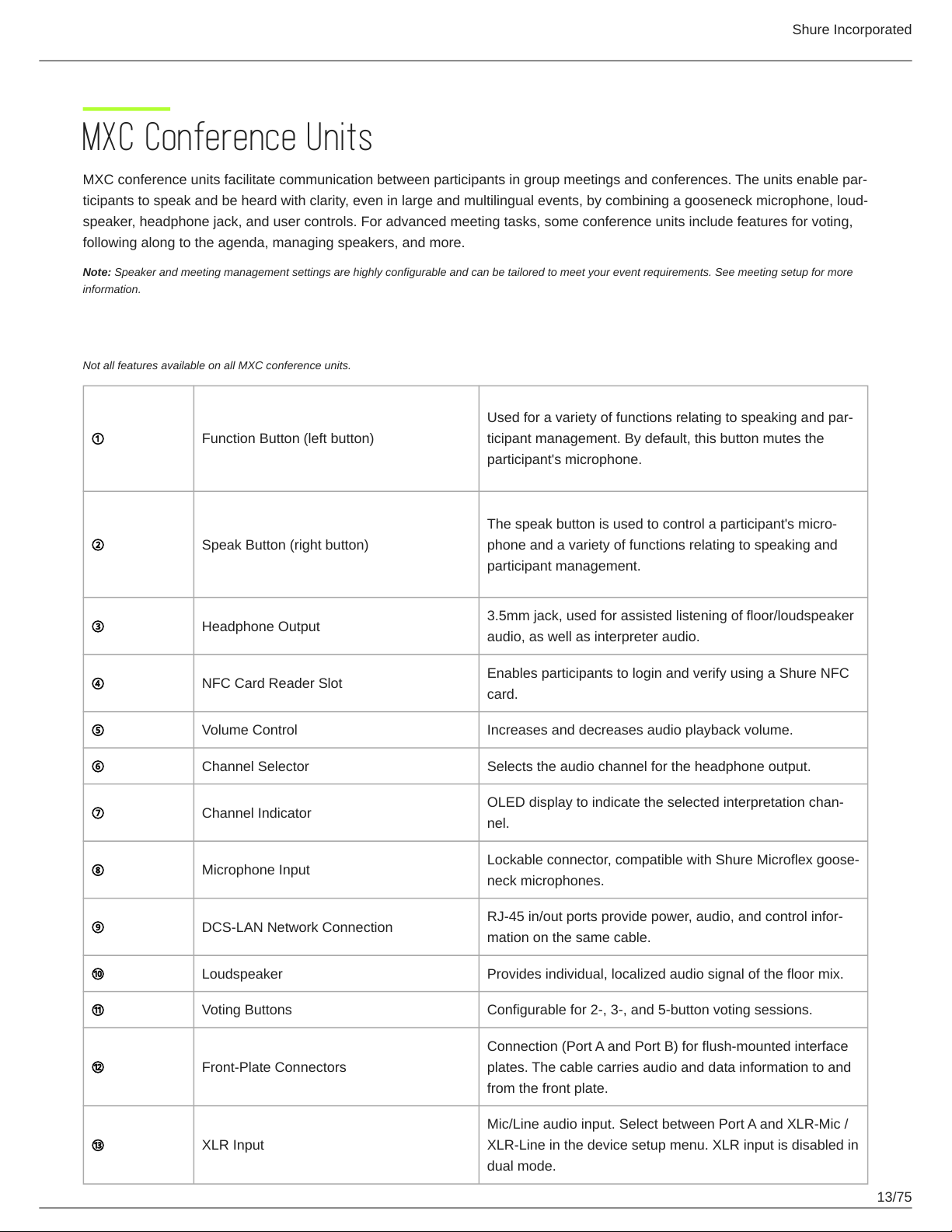
MXC Conference Units
MXC conference units facilitate communication between participants in group meetings and conferences. The units enable par-
ticipants to speak and be heard with clarity, even in large and multilingual events, by combining a gooseneck microphone, loud-
speaker, headphone jack, and user controls. For advanced meeting tasks, some conference units include features for voting,
following along to the agenda, managing speakers, and more.
Note: Speaker and meeting management settings are highly configurable and can be tailored to meet your event requirements. See meeting setup for more
information.
Conference Unit Hardware Descriptions
Not all features available on all MXC conference units.
Used for a variety of functions relating to speaking and par-
① Function Button (left button)
ticipant management. By default, this button mutes the
participant's microphone.
The speak button is used to control a participant's micro-
② Speak Button (right button)
③ Headphone Output
④ NFC Card Reader Slot
⑤ Volume Control Increases and decreases audio playback volume.
⑥ Channel Selector Selects the audio channel for the headphone output.
⑦ Channel Indicator
⑧ Microphone Input
⑨ DCS-LAN Network Connection
⑩ Loudspeaker Provides individual, localized audio signal of the floor mix.
phone and a variety of functions relating to speaking and
participant management.
3.5mm jack, used for assisted listening of floor/loudspeaker
audio, as well as interpreter audio.
Enables participants to login and verify using a Shure NFC
card.
OLED display to indicate the selected interpretation chan-
nel.
Lockable connector, compatible with Shure Microflex goose-
neck microphones.
RJ-45 in/out ports provide power, audio, and control infor-
mation on the same cable.
⑪ Voting Buttons Configurable for 2-, 3-, and 5-button voting sessions.
Connection (Port A and Port B) for flush-mounted interface
⑫ Front-Plate Connectors
⑬ XLR Input
plates. The cable carries audio and data information to and
from the front plate.
Mic/Line audio input. Select between Port A and XLR-Mic /
XLR-Line in the device setup menu. XLR input is disabled in
dual mode.
13/75

Shure Incorporated
⑭ Ground/Lift Toggle Lifts the ground from pin 1 of the XLR input.
⑮ Touch Screen Provides voting and advanced meeting interaction.
Portable Model Variations
MXC615 & MXC620 Conference Unit
Features participant identification using NFC card (MXC620 only), dual-language channel selector and an optional Braille
'Mute/Speak' overlay. Supports chairman, delegate and dual delegate roles.
Note: NFC is not supported with dual-delegate roles.
MXC630 Voting Conference Unit
Conference unit with voting capability, participant identification using NFC card, single-language channel selector, and integrat-
ed Braille 'Mute/Speak' labels for speak and function buttons. Supports chairman and delegate roles.
14/75
Shure Incorporated
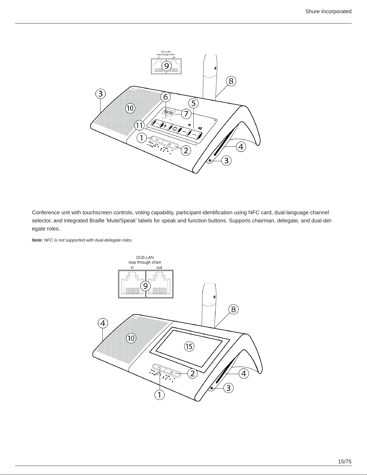
MXC640 Touchscreen Conference Unit
Conference unit with touchscreen controls, voting capability, participant identification using NFC card, dual-language channel
selector, and integrated Braille 'Mute/Speak' labels for speak and function buttons. Supports chairman, delegate, and dual-del-
egate roles.
Note: NFC is not supported with dual-delegate roles.
15/75
Shure Incorporated
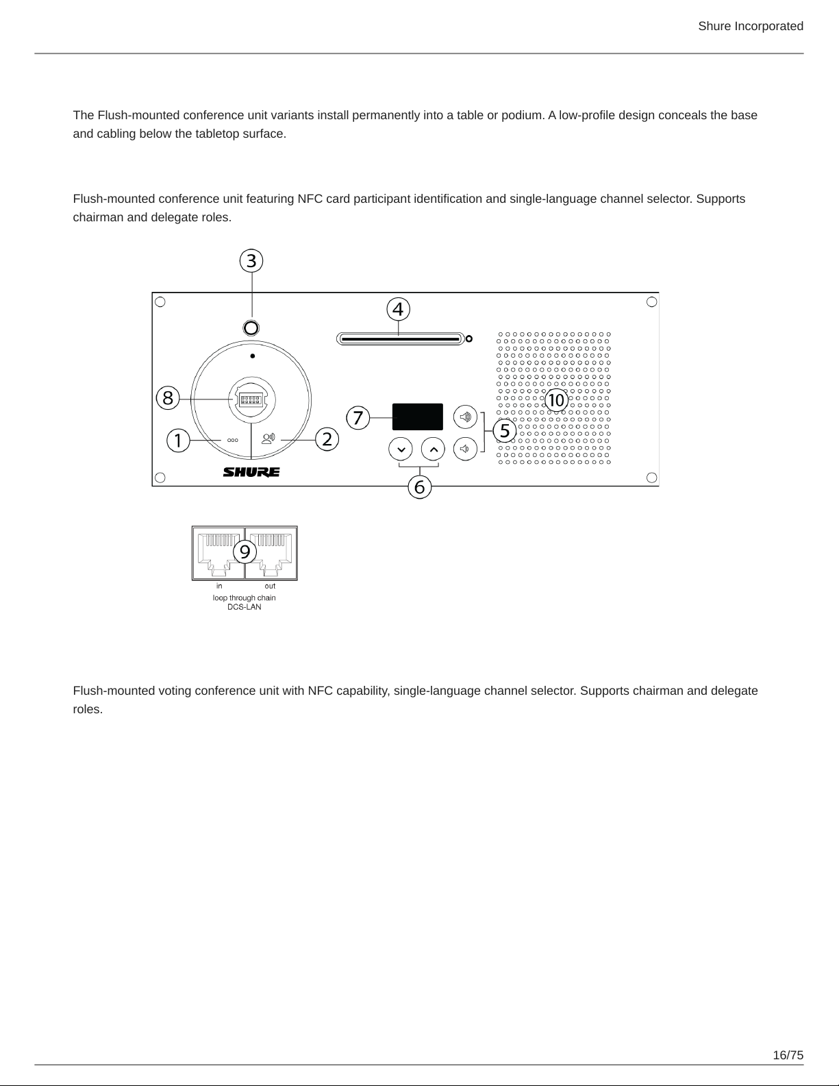
Flush-Mounted Model Variations
The Flush-mounted conference unit variants install permanently into a table or podium. A low-profile design conceals the base
and cabling below the tabletop surface.
MXC620-F Conference Unit
Flush-mounted conference unit featuring NFC card participant identification and single-language channel selector. Supports
chairman and delegate roles.
MXC630-F Voting Unit
Flush-mounted voting conference unit with NFC capability, single-language channel selector. Supports chairman and delegate
roles.
16/75
Shure Incorporated
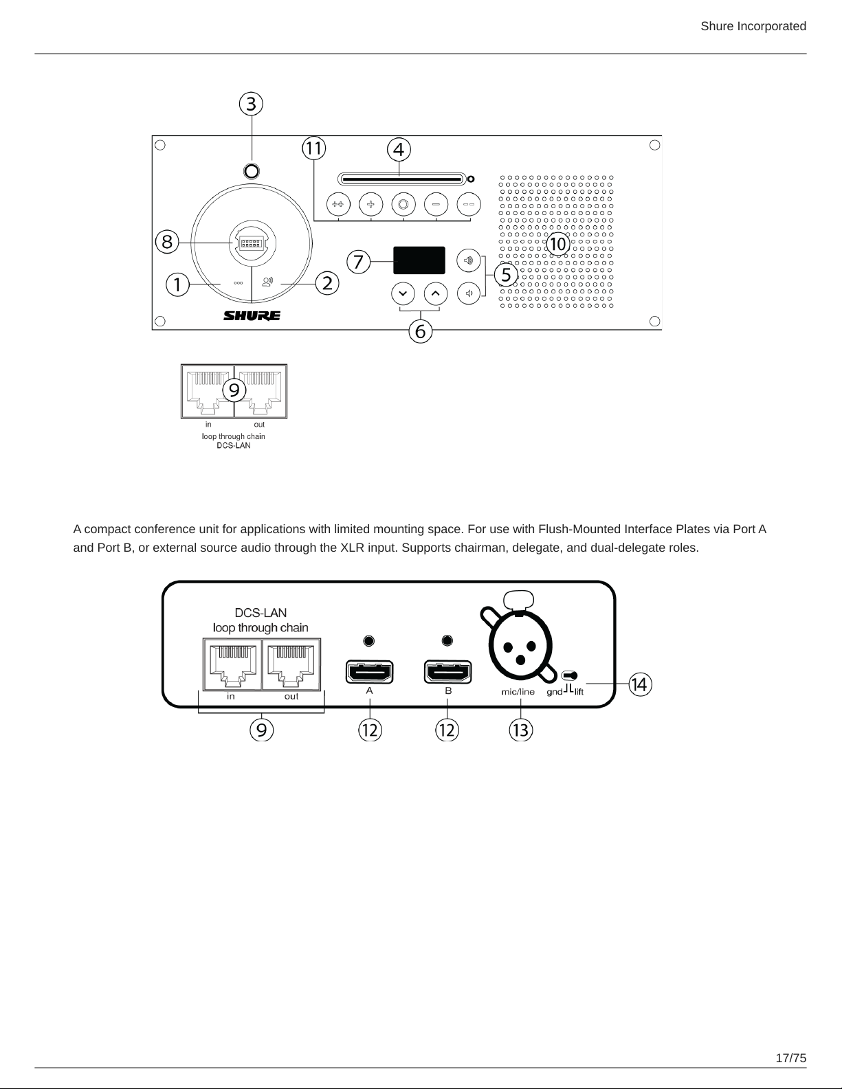
MXCMIU Multi Interface Unit
A compact conference unit for applications with limited mounting space. For use with Flush-Mounted Interface Plates via Port A
and Port B, or external source audio through the XLR input. Supports chairman, delegate, and dual-delegate roles.
17/75
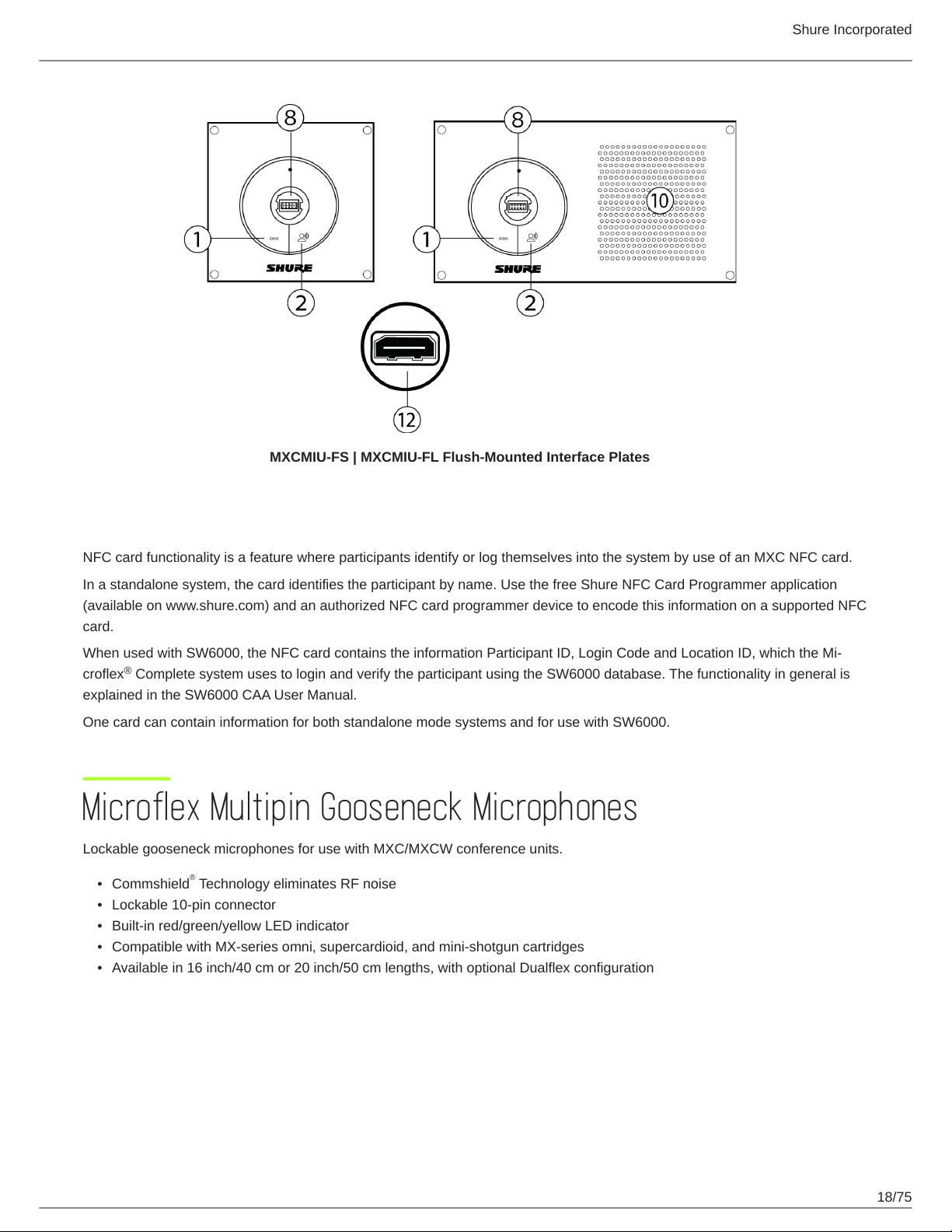
MXCMIU-FS | MXCMIU-FL Flush-Mounted Interface Plates
Shure Incorporated
NFC Card functionality
NFC card functionality is a feature where participants identify or log themselves into the system by use of an MXC NFC card.
In a standalone system, the card identifies the participant by name. Use the free Shure NFC Card Programmer application
(available on www.shure.com) and an authorized NFC card programmer device to encode this information on a supported NFC
card.
When used with SW6000, the NFC card contains the information Participant ID, Login Code and Location ID, which the Mi-
®
croflex Complete system uses to login and verify the participant using the SW6000 database. The functionality in general is
explained in the SW6000 CAA User Manual.
One card can contain information for both standalone mode systems and for use with SW6000.
Microflex Multipin Gooseneck Microphones
Lockable gooseneck microphones for use with MXC/MXCW conference units.
•
Commshield Technology eliminates RF noise
•
Lockable 10-pin connector
•
Built-in red/green/yellow LED indicator
•
Compatible with MX-series omni, supercardioid, and mini-shotgun cartridges
•
Available in 16 inch/40 cm or 20 inch/50 cm lengths, with optional Dualflex configuration
®
18/75
Shure Incorporated
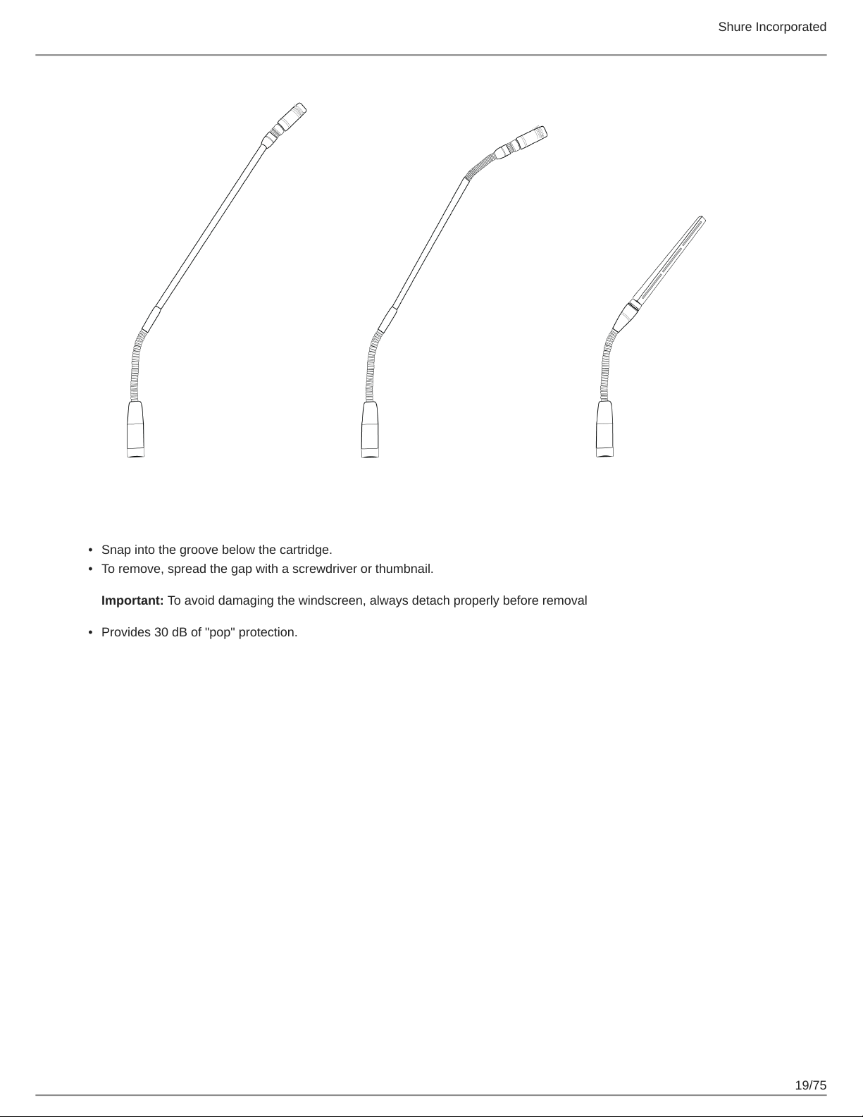
Snap-Fit Windscreen
•
Snap into the groove below the cartridge.
•
To remove, spread the gap with a screwdriver or thumbnail.
Important: To avoid damaging the windscreen, always detach properly before removal
•
Provides 30 dB of "pop" protection.
19/75

Shure Incorporated
Connecting Conference Units and DCS-LAN Components
Conference units and DCS-LAN components are connected in sequence (daisy-chain) using the two RJ45 ports on each unit.
Connectors are not interchangeable: the previous unit must be connected to the IN port, and the following unit to the OUT port.
Power, control data, and audio are transported from one unit to the next over the same shielded Cat5e cable.
To protect the equipment, ensure that the central control unit (CCU) is always off when connecting or disconnecting the con-
ference units. Use any of the four chain connectors (A, B, C, and/or D) for connecting DCS-LAN components.
1.
Power off the CCU to protect the equipment during set up.
2.
Connect a chain output on the CCU to the first conference unit with the shielded Cat5e cable.
3.
Connect the rest of the conference units in sequence, using the RJ45 jacks on the bottom of each unit.
20/75
Shure Incorporated
4.5.Use the included cable clamp to secure the cables in place.
Turn on the CCU by pressing the power button. The conference units will power on. The unit is stable once the control
button LEDs stop flashing.
Warning: Do not turn off CCU power until the system has stabilized
Connection Diagrams
The following system diagrams illustrate typical hardware connections to the CCU. Actual installations may use different combi-
nations of hardware, but follow the general concepts outlined below.
Note: Flush-mount and portable conference units are interchangeable in the following drawings, unless noted.
Basic Setup with Conference Units
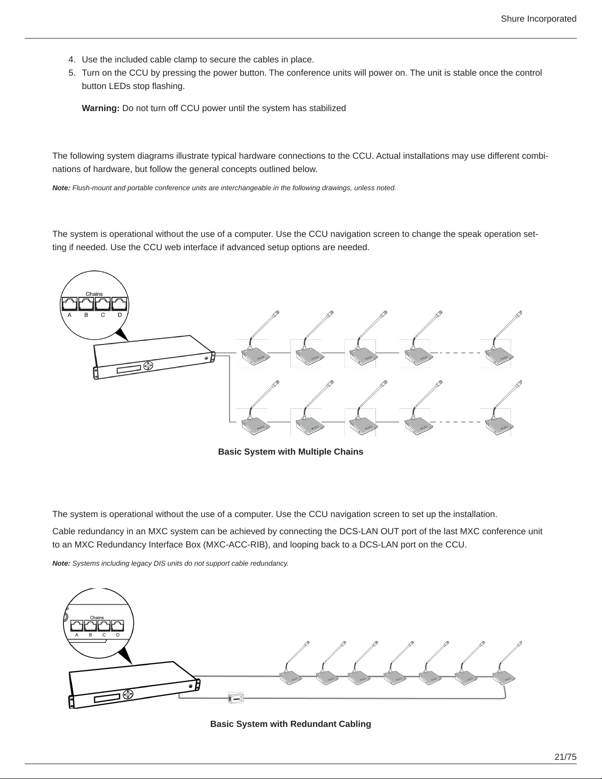
The system is operational without the use of a computer. Use the CCU navigation screen to change the speak operation set-
ting if needed. Use the CCU web interface if advanced setup options are needed.
Basic System with Multiple Chains
Redundancy
The system is operational without the use of a computer. Use the CCU navigation screen to set up the installation.
Cable redundancy in an MXC system can be achieved by connecting the DCS-LAN OUT port of the last MXC conference unit
to an MXC Redundancy Interface Box (MXC-ACC-RIB), and looping back to a DCS-LAN port on the CCU.
Note: Systems including legacy DIS units do not support cable redundancy.
Basic System with Redundant Cabling
21/75
Shure Incorporated
Computer for Advanced Control
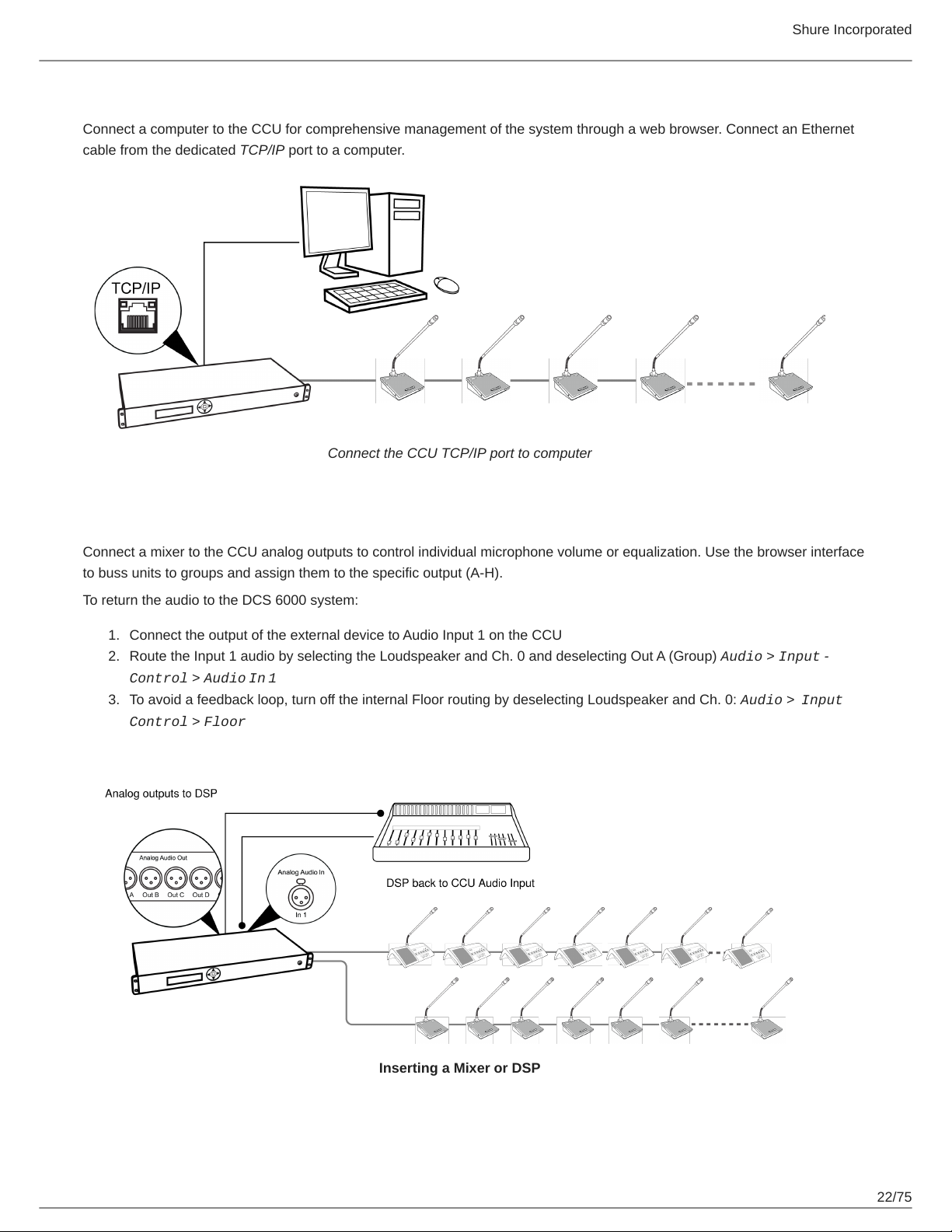
Connect a computer to the CCU for comprehensive management of the system through a web browser. Connect an Ethernet
cable from the dedicated TCP/IP port to a computer.
Connect the CCU TCP/IP port to computer
Mixer or DSP
Connect a mixer to the CCU analog outputs to control individual microphone volume or equalization. Use the browser interface
to buss units to groups and assign them to the specific output (A-H).
To return the audio to the DCS 6000 system:
1.
Connect the output of the external device to Audio Input 1 on the CCU
2.
Route the Input 1 audio by selecting the Loudspeaker and Ch. 0 and deselecting Out A (Group) Audio > Input
Control > Audio In 1
3.
To avoid a feedback loop, turn off the internal Floor routing by deselecting Loudspeaker and Ch. 0: Audio > Input
Control > Floor
Inserting a Mixer or DSP
22/75
Shure Incorporated
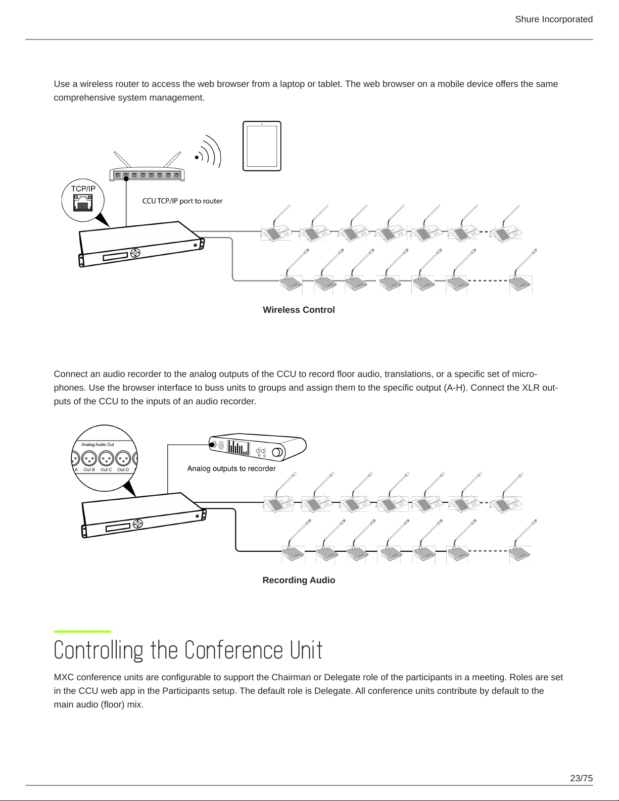
Tablet or Laptop for Wireless Control
Use a wireless router to access the web browser from a laptop or tablet. The web browser on a mobile device offers the same
comprehensive system management.
Wireless Control
Audio Recorder
Connect an audio recorder to the analog outputs of the CCU to record floor audio, translations, or a specific set of micro-
phones. Use the browser interface to buss units to groups and assign them to the specific output (A-H). Connect the XLR out-
puts of the CCU to the inputs of an audio recorder.
Recording Audio
Controlling the Conference Unit
MXC conference units are configurable to support the Chairman or Delegate role of the participants in a meeting. Roles are set
in the CCU web app in the Participants setup. The default role is Delegate. All conference units contribute by default to the
main audio (floor) mix.
23/75
 Loading...