

Page 1
Model MX692
User Guide
SHURE MX692 WIRELESS BOUNDARY MICROPHONE TRANSMITTER
• Integrated functionality of Microflex
boundary microphone and UC Series
wireless transmitter
• Frequency agile transmitter offers
over 100 user selectable channels for
UA and UB frequency bands; run up
to 32 systems simultaneously
• User programmable touch-sensitive
switch and status LED
• 9V battery-powered with 3-stage
battery life LED indicator
• Thread mount cartridge connection
for easy field replacement
• Internal antenna
• Requires Shure UC4 receiver (sold
separately)
©2004, Shure Incorporated
27A8828 (Rev. 2)
Printed in U.S.A.
Page 2

TABLE OF CONTENTS: ENGLISH
Introduction . . . . . . . . . . . . . . . . . . . . . . . . . . . . . . . . . . . . . . . . . . . . . . . . . . 2
MX692 Features and Controls. . . . . . . . . . . . . . . . . . . . . . . . . . . . . . . . . . . . 3
MX692 Features and Controls Continued . . . . . . . . . . . . . . . . . . . . . . . . . . . 4
Checking and Replacing the Battery . . . . . . . . . . . . . . . . . . . . . . . . . . . . . . . 5
Adjusting the Transmitter Gain Level. . . . . . . . . . . . . . . . . . . . . . . . . . . . . . . 6
Changing the Transmitter Group/Channel Settings. . . . . . . . . . . . . . . . . . . . 6
Positioning the Microphone . . . . . . . . . . . . . . . . . . . . . . . . . . . . . . . . . . . . . . 7
Positioning Multiple Microphones . . . . . . . . . . . . . . . . . . . . . . . . . . . . . . . . . 8
Positioning the Receiver . . . . . . . . . . . . . . . . . . . . . . . . . . . . . . . . . . . . . . . . 9
Removing the Grille . . . . . . . . . . . . . . . . . . . . . . . . . . . . . . . . . . . . . . . . . . . 10
Additional or Replacement Cartridges . . . . . . . . . . . . . . . . . . . . . . . . . . . . . 11
The Internal DIP Switches . . . . . . . . . . . . . . . . . . . . . . . . . . . . . . . . . . . . . . 12
Customizing Microphone Switch Functionality . . . . . . . . . . . . . . . . . . . . . . 13
Tips for Optimum Performance . . . . . . . . . . . . . . . . . . . . . . . . . . . . . . . . . . 14
Using the MX692 in Large Installations . . . . . . . . . . . . . . . . . . . . . . . . . . . . 14
Troubleshooting . . . . . . . . . . . . . . . . . . . . . . . . . . . . . . . . . . . . . . . . . . . . . . 15
Specifications. . . . . . . . . . . . . . . . . . . . . . . . . . . . . . . . . . . . . . . . . . . . . . . . 16
English – 1
Page 3

INTRODUCTION
The MX692 wireless boundary microphone is for use in a variety of boardroom, education,
government, and house of worship applications that require a clean, cable-free installation. Additionally, the MX692 is useful in retrofit installations where the modification of existing architecture and furnishings is unwelcome, and in facilities where a flexible, mobile audio system is
required.
The user-programmable mute switch and interchangeable microphone cartridges allow customization of microphone behavior and audio response to suit many applications. The transmitter antenna is mounted internally, giving the microphone a sleek appearance.
The MX692 integrates a boundary microphone and a wireless transmitter. The transmitter
broadcasts on the UA (782.125–805.750 MHz) and UB (692.500–715.625 MHz) frequency
bands. These frequencies are legal for broadcast in the U.S., Canada, Central and South America, and Australia.
The Shure UC Wireless system divides frequency bands into “groups” and “channels.” Up to
sixteen individual MX692 transmitter/UC4 receiver pairs, each with its own channel, may be assigned to a single group. With two frequency bands to choose from, it is possible to run up to 32
microphones simultaneously in a single sound system.
English – 2
Page 4
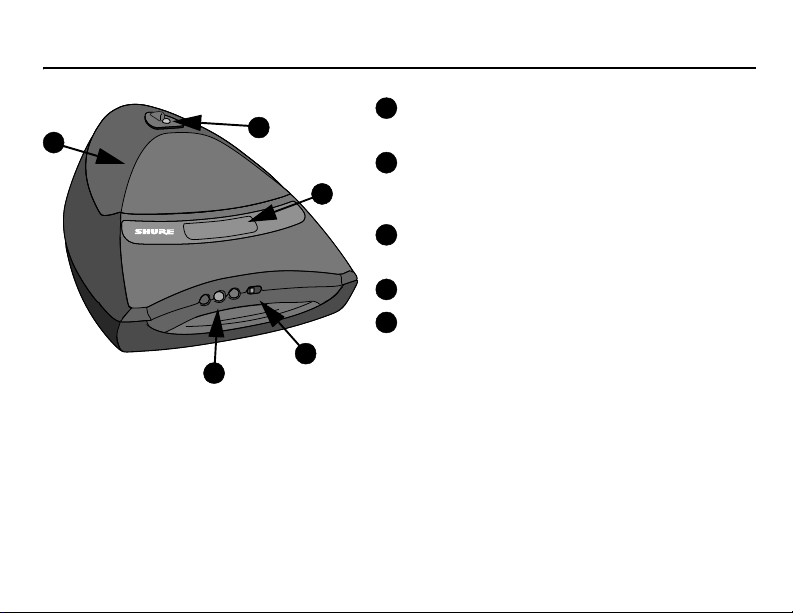
MX692 FEATURES AND CONTROLS
5
1
2
MICROFLEX
•
H
S
U
P
•
4
3
1
2
3
4
5
English – 3
Microphone Status LED
Microphone is active when lit.
Programmable Touch-sensitive Switch
Touch to mute or activate microphone,
depending on logic settings.
Power/Battery Life Gauge
LED color indicates battery power status.
Power On/Off Switch
Protective Grille
Grille can be removed to access microphone
cartridge and DIP switches.
Page 5
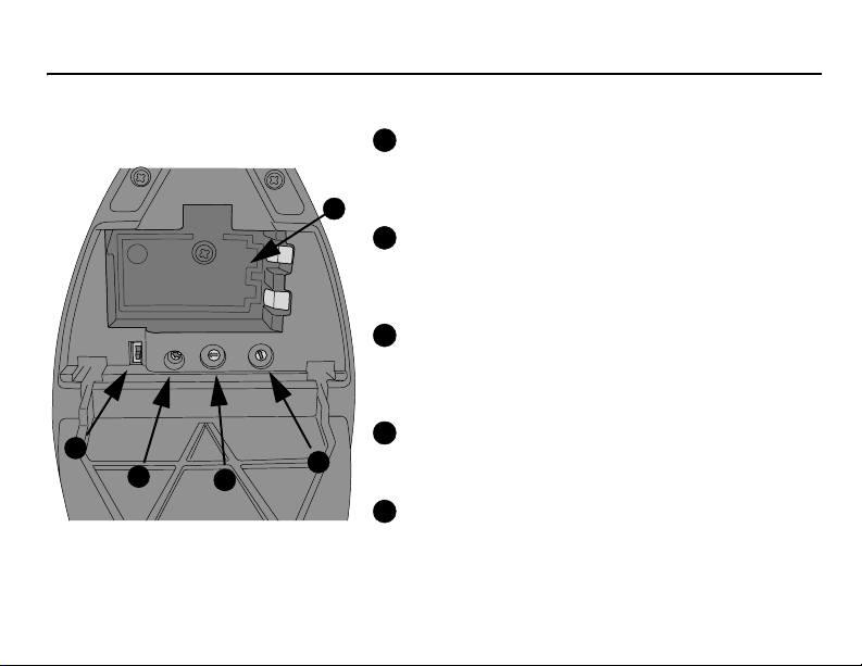
MX692 FEATURES AND CONTROLS CONTINUED
To access gain and channel settings, open the battery compartment door.
1
Input Attenuation Control
This two position switch lets you select either 0 dB or
20 dB attenuation, depending on the volume of the
5
5
4
3
2
3
6
4
2
7
1
1
5
8
0
0
9
6
A
F
9
B
E
7
D
C
8
1
2
3
4
talker’s voice.
2
Transmitter Output Gain Control
Changes the audio level to accommodate various
input volumes. Use the supplied screwdriver to make
adjustments.
3
Channel Setting Control (green dial)
Rotating the Channel dial changes the Channel
setting. Use the supplied screwdriver to make
adjustments.
4
Group Setting Control (red dial)
Rotating the Group dial changes the Group setting.
Use the supplied screwdriver to make adjustments.
5
Battery Compartment
Holds one 9V battery
English – 4
Page 6
CHECKING AND REPLACING THE BATTERY
A
B
C
D
E
F
0
1
2
3
4
5
6
7
8
9
0
1
2
3
4
5
6
7
8
9
To check the battery charge:
1. Turn the transmitter switch to on
2. Verify that one of the battery power LEDs is glowing (see page 3).
3. The amount of battery life remaining is indicated by which LED is lit, as shown in
the following table:
Transmitter LED Color Remaining Operating Time
Green 2 to 8 hours
Amber 45 minutes to 2 hours
Red 45 minutes or less
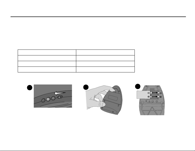
Replacing the battery:
1
2
3
For extended performance, use a 9V lithium battery. Rechargeable, carbon-zinc, and zinc-
chloride batteries are not recommended.
English – 5
Page 7

ADJUSTING THE TRANSMITTER GAIN LEVEL
A
B
C
D
E
F
0
1
2
3
4
5
6
7
8
9
0
1
2
3
4
5
6
7
8
9
If transmitter gain
is set correctly, the
audio LED meter on
the UC4 receiver
should reach amber
during normal speech
-20 dB
0
speech. If transmitter output needs to be increased or decreased, adjust the output gain
control.
Set the input attenuation control switch to 9
dB for normal use (default) or -20 dB for loud
voices (this is rare).
and momentarily flash red during the loudest
CHANGING THE TRANSMITTER GROUP/CHANNEL SETTINGS
For a wireless transmitter such as the MX692
to communicate with a receiver, the transmitter
and receiver must be communicating on the
same frequency. The frequency is set by changing the transmitter and receiver “group” and
“channel” settings. For a MX692 transmitter to
communicate with a UC4 receiver, the two must
have matching group and channel settings.
See the Shure website for recommended
group and channel settings for your area.
English – 6
To change MX692 group and channel set-
tings:
1. Turn the transmitter off.
2. Using the supplied
screwdriver, rotate the
GROUP dial (see
page 4) until the desired
setting is reached. Then
rotate the CHANNEL dial until the desired
setting is reached.
Page 8

POSITIONING THE MICROPHONE
With the standard cardioid cartridge installed, the
MX692 will pick up audio at conversational volume levels
within 1.5 M (5 ft.) in a 130 degree range.
As a general rule, a single microphone should be
used for every two people speaking.
If a tighter pickup range is required, a supercardioid
cartridge may be used.
130°
< 1.5M (5 FT.)
English – 7
Page 9

POSITIONING MULTIPLE MICROPHONES
In any installation, good vocal pickup can be
achieved by following the positioning rules on page
7. Maintain at least .3 m (1 ft.) separation between
transmitters. If you experience transmitter interference, increase the distance between transmitters, or
change the channel of one transmitter/receiver pair.
For information on receiver setup and positioning,
see the UC4 Wireless System user guide.
English – 8
Page 10

POSITIONING THE RECEIVER
>2 m (5 ft.)
<75 m (250 ft.) typical¹
MX692
The UC4 receiver may be rack mounted. See page 14 for information on systems with
multiple transmitters and receivers.
¹ Maximum distance depends on signal absorption, reflection, and interference.
English – 9
UC4
Page 11

REMOVING THE GRILLE
1. Open the battery compartment
2. Remove the battery
3. Loosen and remove the screw at the base of the
battery compartment
4. Remove the retainer from the top of the microphone
English – 10
5. Insert the screwdriver into the opening above the
battery compartment
6. Press gently on the underside of the microphone
grille with the tip of the screwdriver until the grille
pops out
Page 12

ADDITIONAL OR REPLACEMENT CARTRIDGES
Additional or replacement cartridges may be purchased for the MX692. For more information or
to order cartridges, contact the Shure service department or an authorized Shure service center.
To replace the microphone cartridge:
1. Remove the grille (see page 10)
2. Loosen the screw and remove the cartridge clamp
3. Twist to remove the existing cartridge
4. Reverse procedure to install new cartridge
Omnidirectional Cartridge ......................................... R183B
Supercardioid Cartridge ............................................ R184B
Cardioid Cartridge..................................................... R185B
English – 11
Page 13

THE INTERNAL DIP SWITCHES
21 *'+
&
The functionality of the touch-sensitive switch on the microphone’s front panel (see page 3)
can be customized using the internal DIP switches. See page 13 for customization options.
English – 12
Page 14

CUSTOMIZING MICROPHONE SWITCH FUNCTIONALITY
DESIRED SWITCH
FUNCTIONALITY
Push to mute, release to talk (as
shipped)
DESIRED LED FUNCTIONALITY DIP SWITCH SETTING
LED on when microphone is active
Push to talk release to mute LED on when microphone is active
Toggle: push on/push off LED on when microphone is active
Note: switch 4 of the MX692 DIP switch panel is not active
English – 13
G
N
D
O
H
0
4
2C
3
1
2
4
G
N
D
O
H
0
4
2C
3
1
2
4
G
N
D
O
H
0
4
2C
3
1
2
4
G
N
D
O
H
0
4
2C
3
1
2
4
Initially Muted Initially Active
Page 15

TIPS FOR OPTIMUM PERFORMANCE
• Maintain a line of sight between transmitter and receiver antennas.
• Avoid using the MX692 microphone on metal surfaces.
• Avoid placing laptop computers or other obstructions in front of the microphone during use.
• The MX692 wireless microphone/transmitter must be used with the Shure UC4 wireless
receiver.
USING THE MX692 IN LARGE INSTALLATIONS
• When using multiple receivers in a single location, use successive channels within the
same group.
• Use the UA845 UHF Antenna Distribution System to split the signal from one pair of antennas to multiple UC4 receivers.
• To improve RF reception, use the UA500 Remote Mount Antenna Kit to mount 1/2-wave
receiver antennas closer to the transmitters.
• For installations with long cable runs, use the UA830 UHF In-Line Antenna Amplifier. If a
cable run exceeds 50 ft., two UA830’s may be chained together.
English – 14
Page 16

TROUBLESHOOTING
If you experience difficulty, check the following:
• Make sure both the transmitter and the receiver are turned on.
• Check the MX692 battery gauge. Replace the battery if necessary.
• Make sure the transmitter and receiver frequency group/channel settings are identical.
• Make sure there is an unobstructed line-of-sight between the transmitter and receiver.
• If necessary, reposition the receiver, or decrease the distance between transmitter and
receiver.
• Remove local sources of RF interference, such as lighting equipment.
For in-depth troubleshooting, see your UC Wireless System user guide.
English – 15
Page 17

SPECIFICATIONS
Frequency response (see insert)
50 to 17,000 Hz
Polar pattern (see insert)
Cardioid (supplied)
Current drain
62 ± 10 mA, typical (Vss = 6.0 to 9.6 VDC)
Battery life
7 hours (based on alkaline battery)
Dynamic range
>100 dB minimum, A-weighted
Gain Adjustment Range
-6 to 34 dBs
Modulation
+/-45 kHz deviation
Polarity
Positive pressure on the diaphragm produces a
positive voltage on pin 2 of the XLR output of the
UC4 receiver.
Transducer type
Electret condenser
Power Requirements
9V alkaline battery
Temperature Range
Operating: (20° to 120° F)
Storage: (-20° to 165° F)
RF Carrier Frequency Range
692–716 MHz (UB)
782–806 MHz (UA)
Working Ranges
75 m (250 ft.) typical
250 m (800 ft.) line-of-sight
Note: actual working range depends on RF sig-
nal absorption, reflection, and interference
Minimum Distance Between Transmitters
.3 m (1 ft.)
RF Power Output
50 mW Max (conducted)
30 mW Typical (radiated)
Certification
See insert
English – 16
Page 18

Mute Circuitry
D
3
s
-
-
a
-
o
e
r
o
a
e
e
Dimensions, Polar Patterns and Frequency Response
131 mm (5.17 in.)
92 mm (3.625 in.)
90°
120°
60°
150°
dB
30°
+20
+10
180°
–20 dB
–15 dB
–10 dB
–5 dB
0
250 Hz
500 Hz
1000 Hz
150°
30°
120°
60°
90°
150°
120°
90°
60°
30°
180°
–20 dB
–15 dB
–10 dB
–5 dB
0
150°
120°
90°
60°
30°
2500 Hz
5000 Hz
10000 Hz
3
0
1
46 mm (1.8 in.)
Certifications and Licensing
Certifications
Type accepted under FCC Part 74 (FCC ID DD4MX692).
Certified by IC in Canada under RSS-123 and RSS-102.
(IC:616A-MX692.)
Operation of this device is subject to the following two conditions: (1) this device may not cause interference, and (2)
this device must accept any interference, including interference that may cause undesired operation of the device.
Licensing Information
Changes or modifications not expressly approved by
Shure Incorporated could void your authority to operate
this equipment.
Licensing of Shure wireless microphone equipment is the
user’s responsibility, and licensability depends on the user’s classification and application, and on the selected frequency. Shure strongly urges the user to contact the
appropriate telecommunications authority concerning
proper licensing, and before choosing and ordering frequencies.
CERTIFICACIONES
T1, T1G: Aceptado por espécimen bajo las normas de la
FCC, parte 74 (FCC ED DD4MX692). Homologado en Canadá por IC bajo la norma RSS-123 y RSS-102 (IC: 616AMX692).
El uso de este dispositivo está sujeto a las dos condiciones siguientes: (1) no se permite que este dispositivo
cause interferencias y (2) este dispositivo deberá aceptar
interferencias, incluso las que pudieran causar su mal funcionamiento.
INFORMACION PARA OBTENCION DE LICENCIAS
Las modificaciones o los cambios efectuados sin la aprobación expresa de Shure Incorporated podrían anular la
autorización concedida para usar el equipo.
La obtención de licencias de operación para equipos de
micrófonos inalámbricos Shure es responsabilidad del
usuario, y la otorgabilidad de licencias dependerá de la
clasificación y la aplicación del usuario y de la frecuencia
seleccionada. Shure recomienda enfáticamente al usuario
ponerse en contacto con las autoridades de telecomunicaciones correspondientes respecto a la obtención de licencias antes de seleccionar y solicitar frecuencias.
–10
2
-20
20 200001000 1000050 100
Normal settings
1
UC4 at maximum high frequency setting4 UC4 at minimum high frequency setting
3
HOMOLOGATION
Type accepté aux termes de la partie 74 (FCC ID
DD4MX692) des réglementations FCC. Homologué par IC
au Canada selon RSS-123 et RSS-102 (IC : 616A-MX692).
L’utilisation de ce dispositif est sujette aux deux conditions
suivantes : (1) ce dispositif ne doit pas causer de parasites
et (2) ce dispositif doit accepter les parasites, y compris
ceux qui pourraient provoquer un fonctionnement non souhaitable du dispositif.
RENSEIGNEMENTS SUR L’OCTROI DE LICENCE
Tout changement ou modification n’ayant pas fait l’objet
d’une autorisation expresse de Shure Incorporated peut
entraîner la nullité du droit d’utilisation de l’équipement.
La licence d’utilisation de l’équipement du microphone
sans fil Shure demeure la responsabilité de l’utilisateur, et
elle dépend de la classification de l’utilisateur et de l’application prévue par lui ainsi que de la fréquence sélectionnée. Shure recommande vivement de se mettre en rapport
avec les autorités compétentes des télécommunications
pour l’obtention des autorisations nécessaires, ainsi
qu’avant de choisir et de commander des fréquences.
UC4 at minimum low frequency setting
2
4
9876543298765432
Hz
CERTIFICADO
Tipo aceito conforme a FCC Parte 74 (FCC I
DD4MX692). Certificado pelo IC no Canadá sob RSS-12
e RSS-102 (IC: 616A-MX692).
A operação deste dispositivo está sujeita às seguinte
condições: (1) este dispositivo não pode causar interferên
cia (2) este dispositivo deve aceitar interferências, incluin
do algumas que possam causar operação não desejad
do dispositivo.
INFORMAÇÕES SOBRE A LICENÇA
Alterações ou modificações não expressamente aprova
das pela Shure Incorporated podem anular a autorizaçã
do usuário para a operação do equipamento.
A licença do equipamento de microfone sem fio da Shur
é de responsabilidade do usuário, e a capacidade de obte
licença depende da classificação e da aplicação d
usuário e da freqüência selecionada. A Shure recomend
enfaticamente ao usuário contatar a devida autoridade d
telecomunicações com relação à devida licença antes d
escolher e encomendar as freqüências.
©2003 Shure Incorporated
Page 19

Audio Circuitry
Page 20

SHURE Incorporated http://www.shure.com
United States, Canada, Latin America, Caribbean:
5800 W. Touhy Avenue, Niles, IL 60714-4608, U.S.A.
Phone: 847-600-2000 U.S. Fax: 847-600-1212 Int’l Fax: 847-600-6446
Europe, Middle East, Africa:
Shure Europe GmbH, Phone: 49-7131-72140 Fax: 49-7131-721414
Asia, Pacific:
Shure Asia Limited, Phone: 852-2893-4290 Fax: 852-2893-4055
 Loading...