

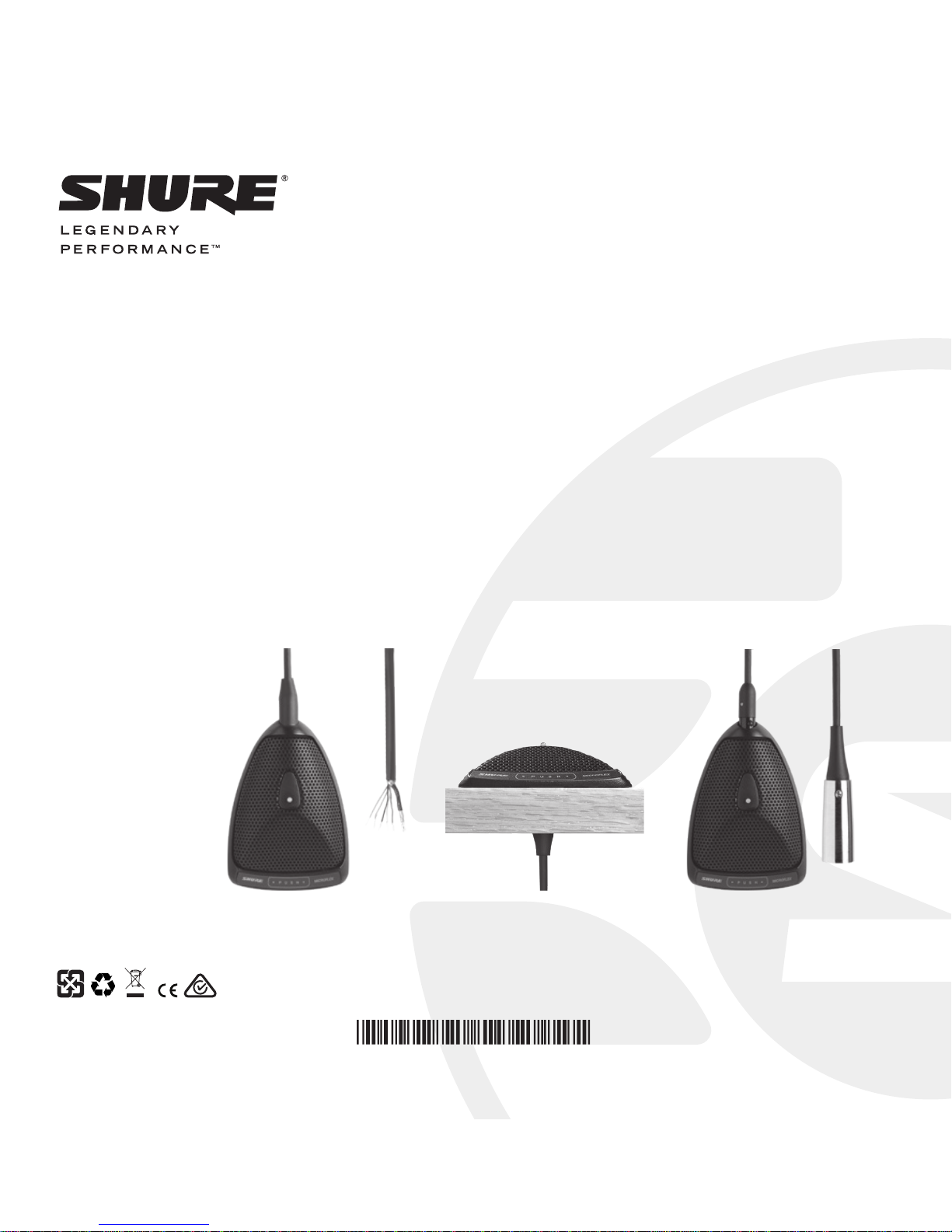
Shure MX300 SERIES User Manual
© 2015 Shure Incorporated
27A30137 (Rev. 1)
MICROFLEX WIRED MICROPHONES
MX300 SERIES
USER GUIDE
Le Guide de l’Utilisateur
Guia del Usuario
Guida dell’Utente
Bedienungsanleitung
取扱説明書
Manual do Usuário
Printed in U.S.A.
MX392 MX392BE MX393
3
Shure Microflex® MX300 Series microphones are surface-mounted electret condenser microphones
designed primarily for mounting on conference tables, stage floors, and lecterns. Their high sensitivity and wide frequency range make them especially suitable for picking up speech and vocals in
sound reinforcement and recording applications. Interchangeable cartridges provide the installer with
greater flexibility and make it possible to easily reconfigure microphone coverage as the need arises.
The MX392 and MX393 models include an internal preamplifier.
MX300 Series microphones take advantage of the principle that, at a barrier or boundary, the sound
pressure level doubles. When placed near a sufficiently large boundary surface, the microphone has
6 dB higher sensitivity and approximately 3 dB greater direct-to-reverberant sound ratio.
MX392-MX392BE-MX393
Boundary Microphones
Features
The MX392, MX392BE, and MX393 feature programmable logic input and output. Additionally
they provide following benefits:
• Flat frequency response across the vocal
range for uncolored sound
• Interchangeable cartridges that provide a
choice of polar pattern for each application
• Sleek, low-profile design for surface mounting
• Programmable mute button
• LED indicator
• Logic input/output for remote control or use
with automatic mixers
• RF filtering
Model Variations
MX392: Attached, unterminated cable.
MX392BE: Attached, unterminated cable
configured at the factory for bottom exit.
MX393: Detachable cable with XLR output
connector.
The polar pattern of the included cartridge is
indicated by a model number suffix:
/C Cardioid
/S Supercardioid
/O Omnidirectional
/N Cartridge not included
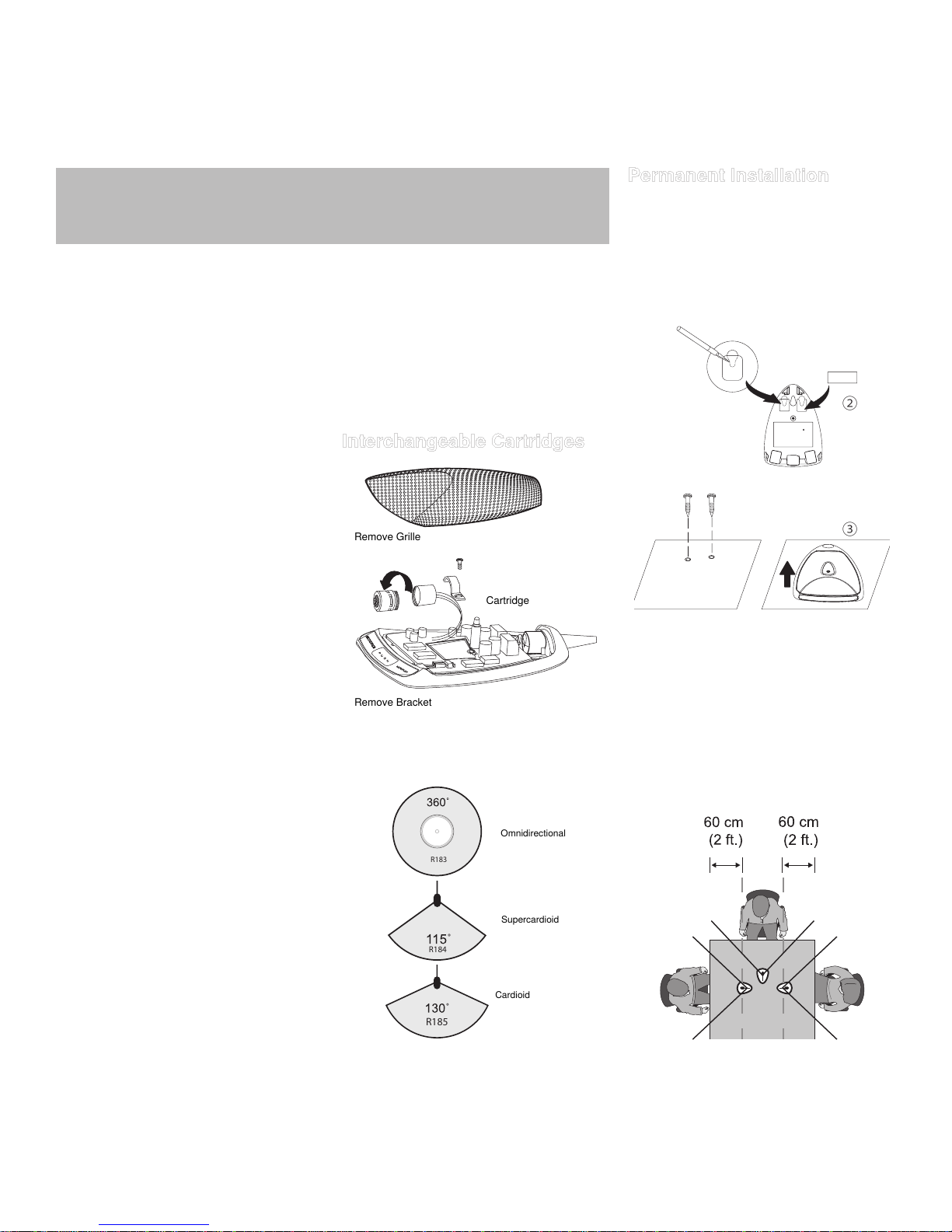
Remove Grille
Remove Bracket
Cartridge
Permanent Installation
MX392 and MX393
1. Remove grille to access mounting key holes.
2. Cut slots into pads.
3. Slide microphone forward to engage screws
in slots.
Note: If using rear side-exit cable option, only
drill two outer holes.
②
③
Microphone Placement
For best low-frequency response and rejection
of background noise, place the microphone on
a large, flat surface, such as a floor, table, or
lectern.
To reduce reverberance, avoid reflective surfaces above or to the side of the microphone,
such as beveled sides of pulpits or overhanging
shelves.
Interchangeable Cartridges
115º
115º
115º
Microflex microphones use interchangeable
cartridges that allow you to choose the polar
pattern for different installations.
R183
R184
R185
Omnidirectional
Supercardioid
Cardioid
Cartridge Polar Patterns
4
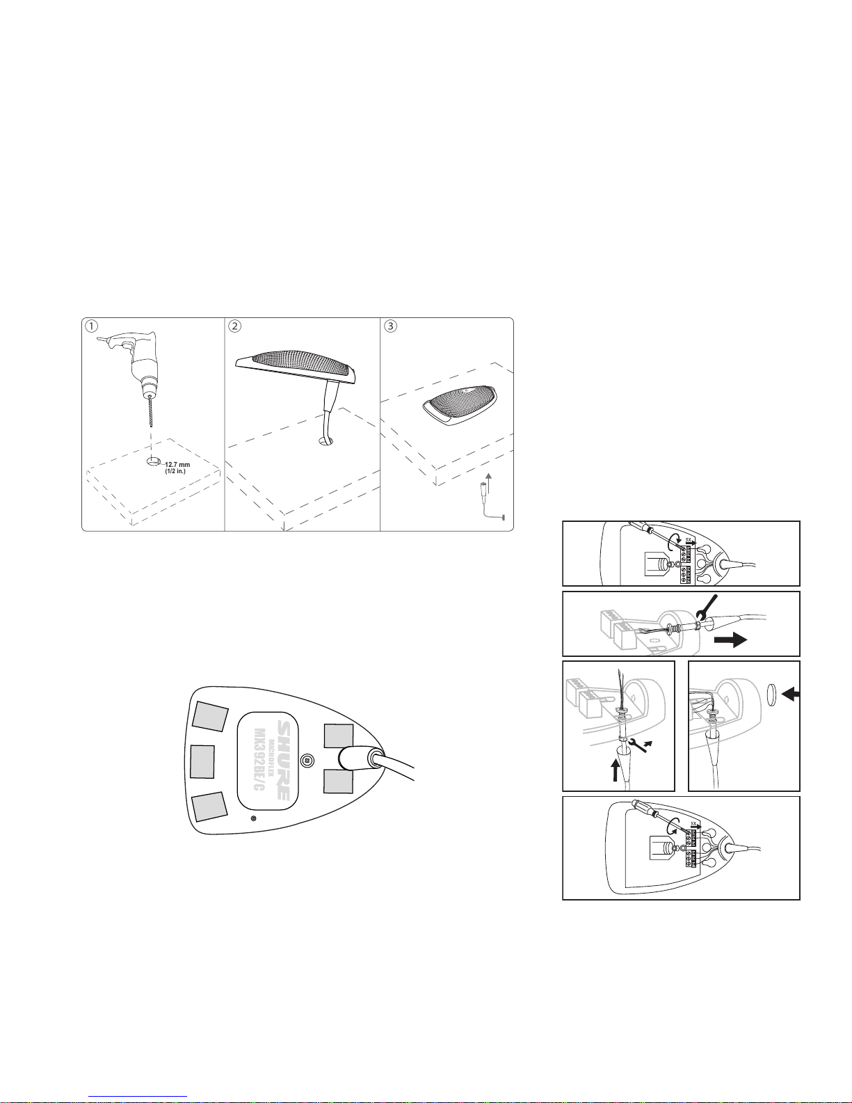
Once placement has been determined, the microphones can be permanently installed. First, drill the
hole in the selected area to allow the bottom entry cable to be conveniently routed out of sight. Then
use the pressure sensitive adhesive to keep the microphone firmly in place.
Drilling the hole:
1. Determine the cutting area for the bottom exit cable and drill a 1/2" (12.7 mm) circular hole.
Remove all debris from the mounting surface.
2. Route the cable through the drilled hole.
3. Connect the integrated XLR cable to a mixer or P.A. system.
Pressure Sensitive Adhesive
Re-Routing Cable for Bottom Exit (If your
MX392 is not BE configured)
②
⑧
⑤
⑥
③
MX392BE
1. Remove the grille.
2. Disconnect wires from screw terminals.
3. Grasp rubber boot within 1/2" of housing, using gas pliers. Rotate boot and cable ccw to
remove connector from threaded "L" bracket.
4. Remove cable from microphone housing.
5. Insert cable through access hole in microphone base.
6. Insert cable connector through hole and
thread it into "L" bracket.
7. If desired, rubber strain relief can be reattached to cable end or removed from cable
before fastening it to bracket.
8. Re-connect wires to proper screw terminals
on circuit board.
9. Insert supplied round rubber plug into unused
side cable exit.
10. Reinstall grille and foam screen.
11. Insert cable through hole in mounting
surface. Secure microphone to mounting
surface.
1. Thoroughly clean the application area with the included alcohol wipe. Removing the dust will allow
the microphone to adhere well.
2. Remove the adhesive backing and gently set the microphone into position.
3. Once the microphone is in position, firmly apply pressure to the microphone.
Note: The pressure sensitive adhesive will be extremely difficult to move once pressure has been
applied.
MX392BE/C
MICROFLEX
Bottom view of MX392BE/C with adhesive pads
12.7 mm
(1/2 in.)
① ② ③
 Loading...