

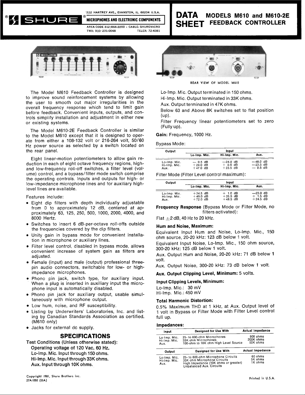
OVERALL DIMENSIONS - FIGURE
Phase:
Pin 3 of
the Microphone lnput is in phase with pin 3 of blue lead to the neutral terminal of the plug. The
the Microphone Output and out of phase with the tip of
Aux. Output and the tip of the Aux. Input.
Filter Characteristics:
Moving Filter Frequency control from
gain by 12 d~ t2
,j~
at frequency of maximum attenua-
0 to 12 reduces
tion. This center frequency is within -+20% of nominal
frequency.
One octave from center frequency, moving
Filter Frequency control from 0 to 12 reduces gain by
3.5 dB
t1 dB.
Below 63 switch: 6 dB per octave slope, 9 dB down
(+2 dB) at 20 Hz.
the "live" or "hot" terminal of the plug, and the
green/yellow lead is the grounding conductor and
should be connected to the ground or earth terminal
of the plug.
Before connecting the
the line voltage selector slide switch on the rear panel
(Item 22 of Figure 3) must be set to the proper posi-
To change the selector switch to the 108-132
tionV.A.C. position, loosen the mounting screw holding
the switch locking tab until the tab can be rotated
away from the switch lever. Tighten the mounting
screw
and
Above 8K switch: 6 dB per octave slope, 8 dB down
(+2 dB) at 20 kHz.
Typical filter frequency response characteristics are
shown in Figures 4 and 5. Filters are electrically isolated for minimum phase interaction.
Operating Voltage:
AC Operation:
M610:
M610-2E:
DC
108-132 volts, 50/60 Hz, 3 watts
108-132
rear panel.
Operation: 30 volts * 20% at approximately tacle is a professional three-pin audio connector (fe-
12 mA.
Or
as
selected by
216-264
a
switch
50/60
On
Hz,
the
Temperature Range:
Operating: -7°C to 57°C (20°F to 135°F) receptacle.
Storage: -29°C to
Net Weight:
Packaged Weight:
7I0C(-20°F to 160°F)
1.8 kg (3 Ib, 15 oz)
2.4 kg (5 Ib, 4 oz)
Dimensions:
See Figure 1.
INSTALLATION
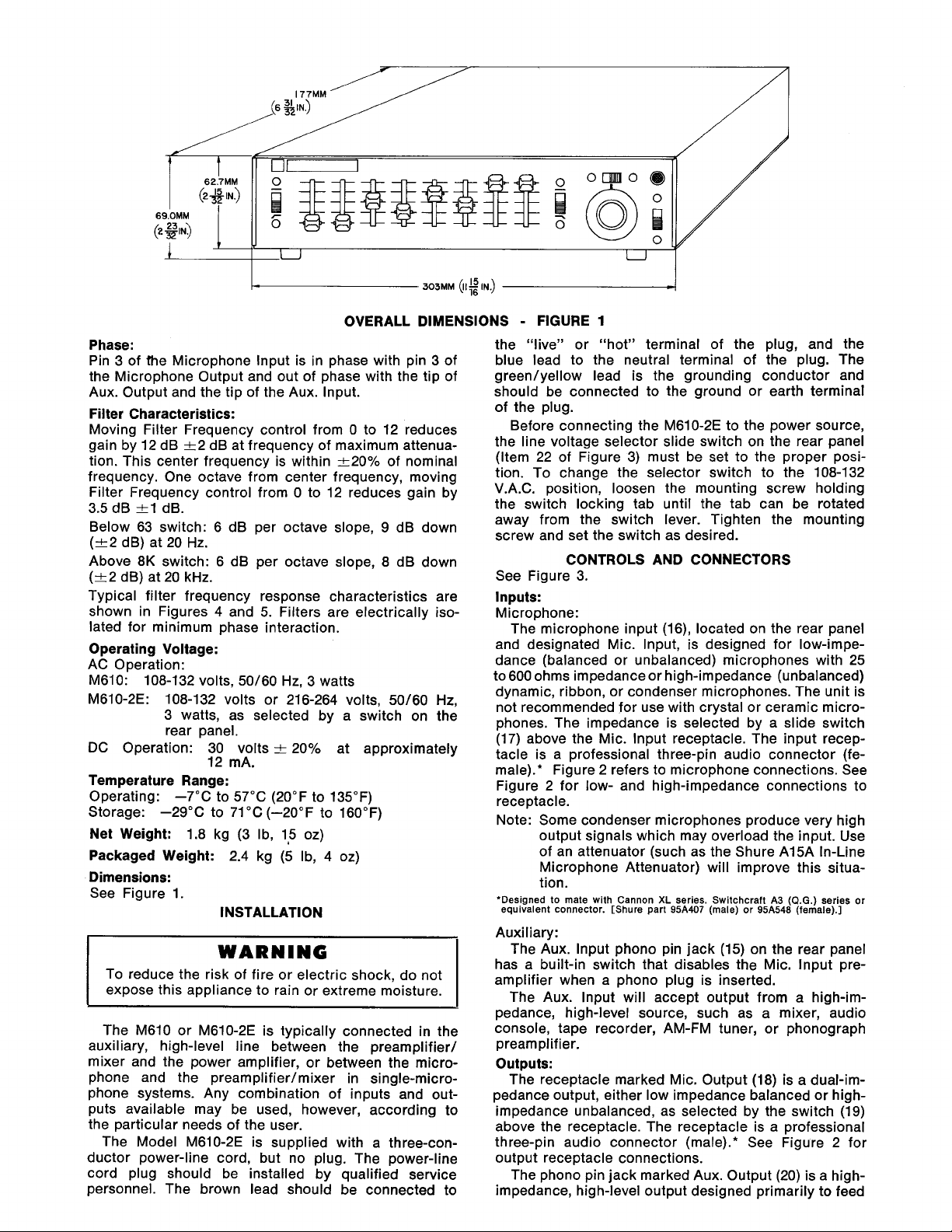
See Figure 3.
Inputs:
Microphone:
The microphone input
and designated Mic. Input, is designed for low-impe-
dance (balanced or unbalanced) microphones with 25
to 600 ohms impedance or high-impedance (unbalanced)
dynamic, ribbon, or condenser microphones. The unit is
not recommended for use with crystal or ceramic micro-
phones. The impedance is selected by a slide switch
(17) above the Mic. lnput receptacle. The input recep-
male).* Figure 2 refers to microphone connections. See
Figure 2 for low- and high-impedance connections to
Note: Some condenser microphones produce very high
output signals which may overload the input. Use
of an attenuator (such as the Shure
Microphone Attenuator) will improve this
tion.
'Designed to mate with Cannon
equivalent connector. [Shure part
1
M610-2E to the power source,
set
the
switch
as
CONTROLS AND CONNECTORS
(16), located on the rear panel
A15A In-Line
XL
series. Switchcraft
95A407
(male) or
A3
95A548
situa-
(Q.G.) series or
(female).]
Auxiliary:
WARNING
To reduce the risk of fire or electric shock, do not
expose this appliance to rain or extreme moisture.
The Aux. lnput phono pin jack (15) on the rear panel
has a built-in switch that disables the Mic. lnput pre-
amplifier when a phono plug is inserted.
The Aux. lnput will accept output from a
high-im-
pedance, high-level source, such as a mixer, audio
The M610 or M610-2E is typically connected in the
console, tape recorder, MVl-FM tuner, or phonograph
auxiliary, high-level line between the preamplifier/ preamplifier.
mixer and the power amplifier, or between the micro-
Outputs:
phone and the preamplifier/mixer in single-micro- The receptacle marked Mic. Output (18) is a dual-imphone systems. Any combination of inputs and out- pedance output, either low impedance balanced or high-
puts available may be used, however, according to impedance unbalanced, as selected by the switch (19)
the particular needs of the user.
The Model
M610-2E is supplied with a three-conductor power-line cord, but no plug. The power-line
cord plug should be installed by qualified service The phono pin jack marked Aux. Output (20) is a
above the receptacle. The receptacle is a professional
three-pin audio connector (male).* See Figure 2 for
output receptacle connections.
high-
personnel. The brown lead should be connected to impedance, high-level output designed primarily to feed

MICROPHONE MIC. INPUT MICROPHONE MIC. INPUT
LOW IMPEDANCE
(BALANCED LINE1
MICROPHONE
MIC. OUTPUT MIC. OUTPUT
LOW
IMPEDANCE HIGH IMPEDANCE
(BPLANCED LINE)
MICROPHONE
INPUT PLUG
OUTPUT
HIGH
CONNECTIONS
PLUG
CONNECTIONS
IMPEDANCE
MICROPHONE CONNECTIONS - FIGURE 2
u
MU\
7~610-ZE
ONLY)
/ \ /
FRONT
CONTROLS AND CONNECTORS - FIGURE
a power amplifier or auxiliary input requiring 0.1 to 2
volts.
Accessory
30
Volts D.C.:
These rear panel jacks (21) provide 30 volts dc for
accessories such as the
A68M Microphone Preamplifier. The jacks are also used as a power input when
using the Model
A67B Battery Power Supply (Acces-
sory). These jacks provide 34 Vdc open circuit (30 Vdc
mA max.).
at 6
Controls
(See Figure 3):
Power Switch and Pilot Light:
The power On-Off switch (14) controls operation of
the unit when it is powered either by the ac line or by
an external dc source. The pilot light (13) indicates
operation only when ac power is used.
Filter Frequency Controls:
The eight linear motion Filter Frequency controls
(9)
located on the front panel are used for adjusting the
(2)-
level of eight octave-spaced bands having center frequencies of 63 Hz, 125 Hz, 250 Hz, 500 Hz, 1 kHz, 2 kHz,
4 kHz, and 8 kHz respectively. The levels of the
octavespaced bands are individually and continuously adjustable from flat at full up position to approximately 12 dB
PANEL
REAR
PANEL
/
u
3
cut at full down position. Figures 4-1 and 4-2 illustrate
frequency response characteristic of each octave
the
filter when
Below 63 and Above
adjust& for 6 dB cut and full cut.
8K
Switches:
The Below 63 filter slide switch (1) reduces the gain
of frequencies below the 63 Hz octave band when placed
in the down position, and the Above
switch (10) reduces the gain of frequencies above the
8 kHz octave band when placed in the down position.
Figure 5 shows the frequency response characteristics
of these filters.
Mode (Filter-Bypass) Switch:
In the Bypass position, the Mode switch (11) disables
the filters and the Filter Level control and sets gain from
Aux. lnput to Aux. Output, or Mic. lnput to Mic. Output,
at approximately unity. The filters and Filter Level control are operative in the Filter position.
Filter Level Control:
The Filter Level control (12) provides up to 24 dB gain
when filters are enabled, as well as gain reduction below
unity. The Filter Level control is used to increase system
gain as filters are adjusted. A setting of
trol will provide approximately unity gain through the
Controller in the Filter mode.
8K
filter slide
4
for this con-

W
m
*
FIGURE
0
FREQUENCY (HZ)
4-1
-EACH FILTER AT
1000 l0,oOO 20,000
6
dB
ATTENUATION
g
:
-10
Y
2
-15
L
2
4
J
20 100 1000 lO.000
E
681 2
FIGURE
INDIVIDUAL OCTAVE FILTER FREQUENCY
CHARACTERISTIC (TYPICAL)
1.
Connect line cord to ac power source or use A67B
Battery Power Supply.
Set panel controls as follows:
On-Off slide switch (14) to ON position.
Mode slide switch (1
Below 63 (1) and Above 8K (10) slide switch to
flat (up) position.
All eight Filter Frequency controls (2)-(9) to full up
position.
Filter Level control (12) to zero (fully counterclock-
wise).
2. Adjust the amplifier gain of the sound system (using the
preamplifier/mixer or power amplifier vol-
ume control) until feedback becomes apparent. Re-
duce the gain setting until it is comfortably below
the feedback level.
3.
Set Mode slide switch (11) to FILTER position. In-
crease Filter Level control (12) until feedback
squeal or ringing is heard.
4. If the feedback sound is high pitched, one of the
four high-frequency Filter Frequency controls (1
kHz through 8 kHz) (6)-(9) will be most effective
in eliminating the feedback. Individually move each
Filter Frequency control slowly from top to bottom
and back to top while listening for feedback. The
control which eliminates feedback with the least
motion should then be moved down only so far as
necessary to eliminate the feedback.
5. If the feedback frequency happens to fall between
the bands covered by two adjacent controls, then it
may be necessary to move down both controls to
obtain the desired feedback suppression.
6. If the feedback sound first noted in step 4 is of a
low frequency, then the adjustment procedure
should be started using the low-frequency (63 Hz
through 500 Hz) Filter Frequency controls (2)-(5).
7.
Having eliminated the first feedback condition, increase the gain of the sound system with the
Filter Level control (12) until feedback is again
noted. Repeat the procedures of the preceding
steps 3 through 6 to eliminate the new feedback
condition. This may require adjustment of a different Filter Frequency control or may require a
further decrease in the control or controls previously moved down.
I
4
681 2
4-2-
FREQUENCY (HZ)
EACH FILTER AT MAXIMUM ATTENUATION
FIGURE
4
OPERATION
1) to BYPASS position.
4
681
2
eopoo
7
8. Repeat step
until either (A), one or more Filter
Frequency controls has been set to maximum attenuation, or (B), feedback appears to occur at more
than one frequency simultaneously. Do not reduce
the setting of any Filter Frequency controls more
than necessary to stop ringing or squealing during
the above procedure.
9. Conduct a talk test through the sound system with
the Mode switch set to FILTER and listen for
ringing. If ringing is noted, attempt to eliminate it
by a slight decrease in the setting of the Filter Level
control or further decrease in the appropriate Filter
Frequency control setting.
During the above procedure, it will not usually be
10.
necessary to set either the Below 63 or Above 8K
switches to the down position to eliminate feedback
unless the pitch of the feedback is extremely low
or extremely high. These switches are primarily intended for improving overall sound quality or tonal
balance, if necessary. After feedback has been
eliminated as outlined above, actuate each switch
and note the tonal character of the system during
the talk test. It will usually be advantageous to actuate the Below 63 switch if the 63 Hz Filter Frequency control is set below 6, and to actuate the
Above 8K switch if the 8 kHz Filter Frequency con-
trol is set below 6.
65
0
W
"7
0
2,
-5
W-''2
$
_I
W
LL
4
6
81
2
4
6
01
2
20 100 1000 lop00 20,000
BELOW
63
AND ABOVE
FREQUENCY
8K
(HZ)
FILTER FREQUENCY CHARACTERISTICS
4 6 81
(TYPICAL)
2
FIGURE 5
WARNING
Voltages in this equipment are hazardous to life.
Refer servicing to qualified service personnel.
OPTIONAL ACCESSORIES
Locking Panel
Rack Panel Kit
This Shure product is guaranteed in normal use to
be free from electrical and mechanioal defects for a
period of one year from date of purchase. Please
retain proof of purchase date. This guarantee includes
all parts and labor. This guarantee is in lieu of any
and all other guarantees or warranties, express or
implied, and there shall be no recovery for any consequential or incidental damages.
Carefully repack the unit and return it prepaid to:
If outside the United States, return the unit to your
dealer or Authorized Shure Service Center for repair.
The unit will be returned to you prepaid.
.......................
......................
.Model A68L
.Model A68R
GUARANTEE
SHIPPING INSTRUCTIONS
Shure Brothers Incorporated
Attention: Service Department
1501 West Shure Drive
Arlington Heights, Illinois 60004

PARTS LIST
BLK.
ITEM SHURE PART NO. SHURE KIT NO.
Dl. D2 86A404 RKC2 I
J I
J2 95A482 RKC83
J3 95A 198 RK122P
J4
J5, J6
I
K
K2-9 90A2044 AND 65A 1239A
PL I
9101, 9103, 0105 86A350 RKC89 4 NPN SILICON TRANSISTOR, HIGH GAIN, LOW NOISE,
0107 SIMILAR TO MOTOROLA 2N5210
9102, 0104, 9106 86A348
9108 SIMILAR TO MOTOROLA 2N5087
0109-Q1 16 866349 RKC9 4 NPN SILICON TRANSISTOR, HIGH GAIN, LOW NOISE.
R5 46A02
R6-R13
51. 52 55A54 RKClO 4 SLIDE SWITCH. DPDT
53 558103
54 55A119
S5,
56 55883
57 55A66
TZ 9082150
TI,
T3 5
F
I
95B634
956450
95A226, 958226
90A 1662
80A79 RKC45
1
46A045
1
A255
BOA155
-
-
-
RKC6
-
- -
RKC3
- -
-
-
-
-
-
-
- -
QTY.
4
-
2
-
-
-
-
-
-
-
-
I
I
I
I
I
IN KIT
DIODE. SILICON, IN4002 OR EQUIVALENT
PHONO JACK WITH SWITCH
INPUT CONNECTOR
OUTPUT CONNECTOR
PHONO JACK
D.C. RECEPTACLE, BLACK AND RED
KNOB
KNOB AND SLEEVE
NEON PILOT LIGHT ASSEMBLY (RESISTOR INTERNAL)
PNP SILICON TRANSISTOR, HIGH GAIN, LOW NOISE,
SIMILAR TO MOTOROLA
ROTARY POTENTIOMETER, 50K, AUDIO TAPER
SLIDE POTENTIOMETER, 250K, AUDIO TAPER
SLIDE SWITCH, DPDT, 3 AMP.. WITH SOLDER SHIELD
SLIDE SWITCH, DPDT
SLIDE SWITCH. DPDl
SLIDE SWITCH. DPDT. 3 AMP.. WITH SOLDER SHIELD
TRANSFORMER AND SHIELD ASSEMBLY
POWER TRANSFORMER
FUSE, 1/16 AMP.
DESCRIPTION
MPS6521
PARTS PLACEMENT

 Loading...