

Page 1

UHF MK2 Wireless System
USER GUIDE SUPPLEMENT
M3 (692–716 MHz)
RENSEIGNEMENT SUPPLÉMENTAIRES
BEDIENUNGSANLEITUNG ANHANG
INFORMACION ADICIONAL
INFORMAZIONI SUPPLEMENTARI
IMPORTANT!
The Shure UHF MK2 Series wireless systems meet the essential requirements of the
European R&TTE Directive 99/5/E and are eligible to bear the CE marking.
Shure UHF components bearing the MK2 insignia are compatible with other Shure
UHF Series wireless systems, but ARE NOT interchangeable with UHF Series components; i.e., a UHF MK2 Transmitter cannot be used with a U4 Receiver that lacks the
MK2 insignia.
SPECIFICATIONS 2. . . . . . . . . . . . . . . . . . . . . . . . . . . . . . . . . . . . . . . . . . . . . . .
UHF WIRELESS SYSTEM COMPA TIBILITY GUIDE 7. . . . . . . . . . . . . . . . .
MASTER LIST 57. . . . . . . . . . . . . . . . . . . . . . . . . . . . . . . . . . . . . . . . . . . . . . . . .
CARACTÉRISTIQUES TECHNIQUES 13. . . . . . . . . . . . . . . . . . . . . . . . . . . .
GUIDE DE COMPATIBILITÉ DU SYSTÈME UHF SANS FIL 19. . . . . . . . . .
LISTE MAÎTRESSE 57. . . . . . . . . . . . . . . . . . . . . . . . . . . . . . . . . . . . . . . . . . . . .
SPEZIFIKATIONEN 24. . . . . . . . . . . . . . . . . . . . . . . . . . . . . . . . . . . . . . . . . . . . .
KOMP ATIBILITÄTSLEITFADEN FÜR UHF–M3–DRAHTLOSSYSTEME 30.
HAUPTLISTE 57. . . . . . . . . . . . . . . . . . . . . . . . . . . . . . . . . . . . . . . . . . . . . . . . . .
ESPECIFICACIONES 35. . . . . . . . . . . . . . . . . . . . . . . . . . . . . . . . . . . . . . . . . . .
GUÍA DE COMPATIBILIDAD DE SISTEMAS INALÁMBRICOS DE UHF 41. . .
LISTA MAESTRA 57. . . . . . . . . . . . . . . . . . . . . . . . . . . . . . . . . . . . . . . . . . . . . . .
DATI TECNICI 46. . . . . . . . . . . . . . . . . . . . . . . . . . . . . . . . . . . . . . . . . . . . . . . . .
GUIDA ALLA COMPATIBILITÀ DEL SISTEMA SENZA FILI UHF 52. . . . . .
L’ELENCO PRINCIPALE 57. . . . . . . . . . . . . . . . . . . . . . . . . . . . . . . . . . . . . . . .
2002, Shure Incorporated
27A8759 (BI)
Printed in U.S.A.
Page 2
SPECIFICATIONS
RF Carrier Frequency Range
692–716 MHz
Working Range
U1, U2: 152.4 m, minimum, under typical conditions; 487.6 m line of sight
NOTE: Actual working range depends on RF signal absorption, reflection and
interference
Audio Frequency Response
50 to 15,000 Hz, ±2 dB.
NOTE: Overall system frequency response depends on the microphone element
Gain Adjustment Range
U1: 0 to 40 dB
U2: 0 to 26 dB
Modulation
±18 kHz deviation compressor-expander system with pre-and de-emphasis
RF Power Output
U1, U2: 10 mW maximum
Dynamic Range
>102 dB, A-weighted
RF Sensitivity
U4S U4D
–110 dBm
12 dB SINAD
–105 dBm
30 dB SINAD
Image Rejection
90 dB typical
Spurious Rejection
75 dB typical
Ultimate Quieting (ref. ±18 kHz deviation)
>100 dB, A-weighted
Audio Polarity
Positive pressure on microphone diaphragm (or positive voltage applied to tip of
WA302 phone plug) produces positive voltage on pin 2 with respect to pin 3 of
low impedance output and the tip of the high impedance 1/4-inch output
System Distortion (ref. ±18 kHz deviation, 1 kHz modulation)
0.3% Total Harmonic Distortion typical
Power Requirements
U1, U2: 1.5V AA alkaline battery (Duracell MN1500 recommended); Nicad optional
U4: 230 Vac , 50/60 Hz
Power Consumption:
U4S: 9.6 W min., 13.2 W max.
U4D: 12 W min.,16 W max.
UA845: 15 W min., 16 W max.
Battery Life (Typical)
U1, U2: 12 hours (with Duracell MN1500 1.5V AA alkaline battery)
Operating Temperature Range
-6° to +49° C
NOTE: Battery characteristics may limit this range
–107 dBm
12 dB SINAD
–102 dBm
30 dB SINAD
2
Page 3
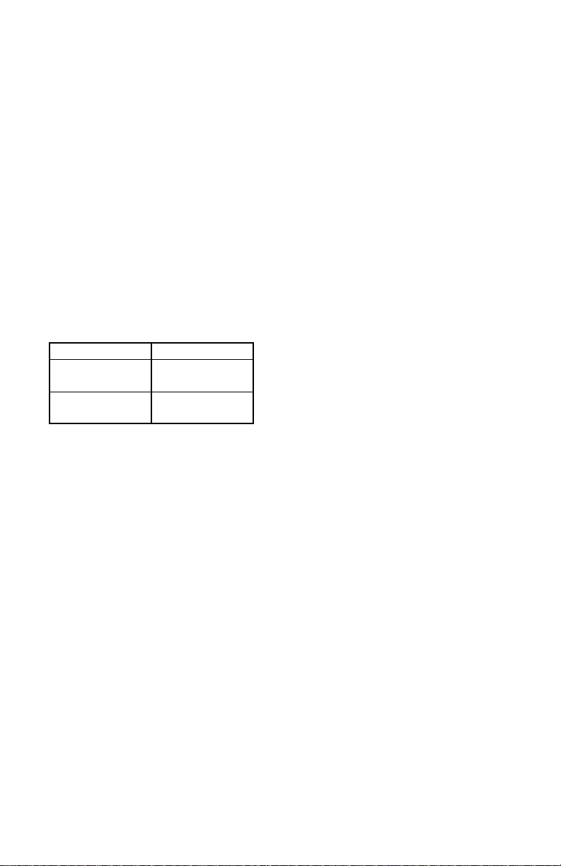
U1 Transmitter Input (Figure 1)
Connector:
Input Configuration:
Actual Impedance:
Maximum Input Level:
TA4F Connector Pin
Assignments:
LEMO Connector
Pin Assignments:
Voltage for Remote Power:
TA4F or LEMO
Unbalanced, active
18 kΩ with lavalier microphone
1 MΩ with instrument cable
6 Vp–p (+7 dBV) for 1% THD at minimum gain
setting using 1 kHz signal.
Pin 1: Tied to Ground
Pin 2: Tied to +5 V
Pin 3: Tied to Audio
Pin 4: Tied thru 20kΩ Resistor to Ground.
(On instrument adapter cable, Pin 4 floats)
Pin 1: Tied to Pin 3 and 10 kΩ to Ground
Pin 2: +5V
Pin 3: Tied to Pin 1
Pin 4: Tied to Shield (Ground for Positive Bias)
+5 V supplied to microphone cartridge
MICROPHONE
ELEMENT
NOTE: LAVALIER MIC TIES PINS 3 AND 4
TOGETHER; GUITAR CABLE DOES NOT.
1
2
3
4
U1 Transmitter Output
Connector:
Actual Impedance:
Nominal Output Level:
Maximum Output Level:
Pin Assignments:
U1/ MIC JACK BOARD
2
2
4
4
500 Ω
3
3
499 Ω
1
499 Ω
AUDIO
27 pF
BIAS
27 pF
SHIELD
1
U1L (LEMO 4 PIN) MIC JACK BOARD
10K Ω
FIGURE 1
+10 dBm
+11 dBm
Shell = Ground
Center = Signal
500 Ω
27 pF
SMC
50 Ω
20K Ω
27 pF
+5 V
AUDIO
GROUND
3
Page 4

U2 Transmitter Input
Input Configuration: Unbalanced, active
Actual Impedance: 20 kΩ
Maximum Input Level: 3 Vp–p (0.5 dBV) for 1% THD at minimum gain
setting using 1 kHz signal.
U2 Transmitter Output
Connector:
Actual Impedance:
Nominal Output Level:
Maximum Output Level:
Pin Assignments:
SMC
50 Ω
+10 dBm
+11 dBm
Shell = Ground
Center = Signal
U4S and U4D Receiver Input
Connector: Antenna Power Input Network Interface
Connector Type: BNC IEC 320 25–Pin D
Actual
Impedance:
Nominal Input
Level:
Maximum Input
Level:
Pin Assignments: Shell = Ground
Voltage for
Remote Power:
50 Ω –– ––
–95 to –30 dBm 230 VAC,
50/60 Hz
+6 dBm
254 VAC, 50/60 Hz ––
(–20 dBm
recommended)
IEC Standard ––
Center = Signal
12 Vdc, 150 mA
–– 5V, 700 mA max.
maximum
CMOS Logic
U4S and U4D Receiver Output
Connector: Monitor Power
Output
Configuration:
Actual
Impedance:
Nominal
Input Level:
Pin
Assignments:
Unbalanced
mono, 1/4 inch
300 Ω –– 1 kΩ 30 Ω See
–– 230 VAC,
Tip = Hot
Ring = Hot
Sleeve = Gnd
Voltage/
Current/
Phantom
Power
Protection?
*Output Level: Microphone Level = Line Level – 30 dB
Yes –– Yes Yes 5V, 700 mA
Output
–– Un-
5A
IEC
Standard
balanced
Tip = Hot
Sleeve =
4
High Z
Audio
Low Z
Audio*
Network
Interface
Balanced See
Appendix
Appendix
–– –– CMOS
1 = Ground
Ring/
2 = Hot
Appendix
3 = Hot
Gnd
resettable
polyfuse
Logic
See
Page 5

Overall Dimensions
U1: 92.2 mm L x 64.7 mm W x 24.2 mm D
U2/58:254 mm L x 50.8 mm Dia.
U2/BETA 58: 254 mm L x 53.2 mm Dia.
U2/87:228.6 mm x 49.2 mm Dia.
U2/BETA 87: 216 mm L x 50.8 mm Dia
U4S/U4D: 44.5 mm H x 482.6 mm W x 295.3 mm D
Net Weight
U1: 175.2 g without battery
U2/58, U2/BETA 58: 375.6 g without battery
U2/87, U2/BETA 87: 303.1 g without battery
U4S: 3.30 kg
U4D: 3.85 kg
Certification
The Shure UHF series wireless systems meet the essential requirements of the
European R&TTE Directive 99/5/EC and are eligible to carry the CE marking.
U1, U2: Conforms to European ETSI Standard EN 300 422 (Parts 1 and 2) and
ETS 300445/A1.
U4, U4D: Conforms to European ETSI Standard EN 300 445/A1 and EN 60950.
THIS RADIO EQUIPMENT IS INTENDED FOR USE IN PROFESSIONAL
ENTERTAINMENT (CLASS I) AND SIMILAR APPLICATIONS.
FURNISHED ACCESSORIES
Microphone Stand Adapter (U2) WA371. . . . . . . . . . . . . . . . . . . . . . . . . . . . . . . . . . . . .
Zipper Bag (U1) 26A13. . . . . . . . . . . . . . . . . . . . . . . . . . . . . . . . . . . . . . . . . . . . . . . . . . .
Zipper Bag (U2) 26A14. . . . . . . . . . . . . . . . . . . . . . . . . . . . . . . . . . . . . . . . . . . . . . . . . . .
Screwdriver 80A498. . . . . . . . . . . . . . . . . . . . . . . . . . . . . . . . . . . . . . . . . . . . . . . . . . . . .
Coaxial Antenna Cable (2 ft) UA802. . . . . . . . . . . . . . . . . . . . . . . . . . . . . . . . . . . . . . . .
1/2 Wave Antenna UA820B. . . . . . . . . . . . . . . . . . . . . . . . . . . . . . . . . . . . . . . . . . . . . . . .
Transmitter Carrying Case 65A8257. . . . . . . . . . . . . . . . . . . . . . . . . . . . . . . . . . . . . . . .
Carrying Case Insert 29B1577. . . . . . . . . . . . . . . . . . . . . . . . . . . . . . . . . . . . . . . . . . . . .
OPTIONAL ACCESSORIES
Instrument Adapter Cable (U1) WA302, WA304. . . . . . . . . . . . . . . . . . . . . . . . . . . . . .
TA4F Female 4–Pin Connector (U1) WA330. . . . . . . . . . . . . . . . . . . . . . . . . . . . . . . . .
In-Line Audio Switch (U1) WA360. . . . . . . . . . . . . . . . . . . . . . . . . . . . . . . . . . . . . . . . . . .
1.8 Meter (6 ft) Receiver-Mixer Cable (
7.6 Meter (25 ft) Antenna Extension Cable UA825. . . . . . . . . . . . . . . . . . . . . . . . . . . .
15.2 Meter (50 ft) Antenna Extension Cable UA850. . . . . . . . . . . . . . . . . . . . . . . . . . .
30.4 Meter (100 ft) Antenna Extension Cable UA8100. . . . . . . . . . . . . . . . . . . . . . . . .
In–Line Active Remote Antenna Kit (692 – 716 MHz) UA830UB. . . . . . . . . . . . . . . .
Antenna/Power Distribution System, 230 Vac UA845UB. . . . . . . . . . . . . . . . . . . . . . .
Directional Antenna UA870UB. . . . . . . . . . . . . . . . . . . . . . . . . . . . . . . . . . . . . . . . . . . . .
1
/4” phone to XLR) WA410. . . . . . . . . . . . . . .
5
Page 6

REPLACEMENT PARTS
Hardware Kit (screwdriver, mounting feet, cable clamps) 90VL1371. . . . . . . . . . . . .
Bulkhead Adapters for Front–Mounting Antennas 95A8647. . . . . . . . . . . . . . . . . . . .
230 VAC Power Cord (Schuko mains connector) 95A8247. . . . . . . . . . . . . . . . . . . . .
304 mm (12 in.) Daisy–Chain Power Cord (230 V) 95A8678. . . . . . . . . . . . . . . . . . .
Cartridge with Grille (U2/58) R158. . . . . . . . . . . . . . . . . . . . . . . . . . . . . . . . . .
SM58
BETA 58A Cartridge with Grille (U2/BETA 58) R179. . . . . . . . . . . . . . . . . . . . . . . . . .
SM87 Cartridge with Grille (U2/87) R165. . . . . . . . . . . . . . . . . . . . . . . . . . . . . . . . . . . .
BETA 87A Cartridge with Grille (U2/BETA 87) R166. . . . . . . . . . . . . . . . . . . . . . . . . .
BETA 87C Cartridge with Grille (U2/BETA 87) RPW100. . . . . . . . . . . . . . . . . . . . . . .
Matte Silver Grille (U2/58) RK143G. . . . . . . . . . . . . . . . . . . . . . . . . . . . . . . . . . . . . . . . .
Matte Silver Grille (U2/BETA 58) RK265G. . . . . . . . . . . . . . . . . . . . . . . . . . . . . . . . . . . .
Matte Silver Grille (U2/BETA 87) RK313G. . . . . . . . . . . . . . . . . . . . . . . . . . . . . . . . . . . .
Black Grille (U2/87) RK214G. . . . . . . . . . . . . . . . . . . . . . . . . . . . . . . . . . . . . . . . . . . . . .
Black Grille (U2/BETA 58) RK323G. . . . . . . . . . . . . . . . . . . . . . . . . . . . . . . . . . . . . . . . .
Black Grille (U2/BETA 87) RK324G. . . . . . . . . . . . . . . . . . . . . . . . . . . . . . . . . . . . . . . . .
Belt Clip (U1) 53A8247A. . . . . . . . . . . . . . . . . . . . . . . . . . . . . . . . . . . . . . . . . . . . . . . . . .
Antenna (U1) 95A8646. . . . . . . . . . . . . . . . . . . . . . . . . . . . . . . . . . . . . . . . . . . . . . . . . . .
Antenna (U2) 95A2029. . . . . . . . . . . . . . . . . . . . . . . . . . . . . . . . . . . . . . . . . . . . . . . . . . .
LICENSING INFORMATION
Changes or modifications not expressly approved by Shure Incorporated could void
your authority to operate the equipment. Licensi ng of Shure wireless microphone
equipment is the u ser’s r esponsibility, a nd l icensability depends o n t he u ser’s c lassification and application, and o n t he s elected frequency. S hure s trongly urges t he user
to contact t he a ppropriate t elecommunications authority concerning p roper l icensing,
and before choosing and ordering frequencies.
R&TTE CONFORMITY INFORMATION
IMPORTANT! Shure Models U1 and U2 Transmitters meet the essential require-
ments of the European R&TTE Directive 99/5/EC and are eligible to carry the CE
marking.
Shure Model U4 Receivers meet the essential requirements of the European R&TTE
Directive 99/5/EC and are eligible to carry the CE marking.
This Radio Equipment is intended for use IN MUSICAL PROFESSIONAL ENTERTAINMENT AND SIMILAR APPLICATIONS.
NOTE: This Radio apparatus may be capable of operating on some frequencies not
authorized in your region. Please contact your national authority to obtain information
on authorized frequencies for wireless microphone products in your region
Frequency Range of Apparatus: 692 MHz – 862 MHz
Licensing: A ministerial license to operate this equipment may be required in certain
areas. Consult your national authority for possible requirements.
Shure Transmitters Models U1 and U2 may be used in the countries and frequency
ranges listed in Table 1.
O682
6
Page 7

Table 1
Country Code U1-M3, U2-M3
A 692–716 MHz* 774–782 MHz* 782–810 MHz* 800–820 MHz* 800–830 MHz* 838–862 MHz*
B 692–716 MHz* 774–782 MHz* 782–810 MHz* 800–820 MHz* 800–830 MHz* 838–862 MHz*
CH 692–716 MHz* 774–782 MHz* 782–810 MHz* 800–820 MHz* 800–830 MHz* 838–862 MHz*
D 692–716 MHz* 774–782 MHz* 782–810 MHz* 800–820 MHz* 800–830 MHz* 838–862 MHz*
E 692–716 MHz* 774–782 MHz* 782–810 MHz* 800–820 MHz* 800–830 MHz* 838–862 MHz*
F 692–716 MHz* 774–782 MHz* 782–810 MHz* 800–820 MHz* 800–830 MHz* *
GB 692–716 MHz* 774–782 MHz* 782–810 MHz* * * 838–862 MHz*
GR 692–716 MHz* 774–782 MHz* 782–810 MHz* 800–820 MHz* 800–830 MHz* 838–862 MHz*
I 692–716 MHz* 774–782 MHz* 782–810 MHz* * * *
IRL 692–716 MHz* 774–782 MHz* 782–810 MHz* 800–820 MHz* 800–830 MHz* 838–862 MHz*
L 692–716 MHz* 774–782 MHz* 782–810 MHz* 800–820 MHz* 800–830 MHz* 838–862 MHz*
NL 692–716 MHz* 774–782 MHz* 782–810 MHz* 800–820 MHz* 800–830 MHz* 838–862 MHz*
P 692–716 MHz* 774–782 MHz* 782–810 MHz* 800–820 MHz* 800–830 MHz* 838–862 MHz*
DK * * 800–810 MHz* 800–820 MHz* 800–830 MHz* *
FIN * * 800,1–810
N * * 800–810 MHz* 800–820 MHz* 800–830 MHz* *
S * * 800–810 MHz* 800–814 MHz* 800–814 MHz* *
All Other
Countries
(692 - 716
MHz)
* * * * * *
*Please contact your national authority for information on available legal frequencies for your area
and legal use of the equipment.
U1-R3, U2-R3
(774 - 782
MHz)
U1-R7, U2-R7
(782 - 810
MHz)
MHz*
U1-R6, U2-R6
(800 - 820
MHz)
800,1–819,9
MHz*
U1-R2, U2-R2
(800 - 320
MHz)
800,1–819,9
MHz*
U1-S2, U2-S2
(838 - 862
MHz)
*
UHF WIRELESS SYSTEM COMPATIBILITY GUIDE
Table 2 provides a convenient overview of frequency–compatible systems in the
692.000 to 716.000 MHz band. Each of the primary groups contains multiple channels
which are all compatible with one another.
Up to 20 Shure UHF Wireless Systems can be operated simultaneouslywithin the
692–716 MHz band if using the discontinued UHF UB versions, or a combination of
UB and MK2 M3 versions. Up to 30 UHF MK2 systems can be operated simultaneously within the 692–716 MHz band.
Note: Combinations of Shure UHF transmitters and UHF MK2 receivers, and combinations of UHF MK2 transmitters and UHF receivers are NOT supposed to work together. Always use a transmitter–receiver combination of the same frequency version
(M3 or UB).
Groups 1–16 MUST be chosen if the installation includes a pure setup of Shure UHF
Wireless Systems (frequency version UB only) or a mixed setup of Shure UHF and
Shure UHF MK2 Wireless Systems (frequency versions UB and M3)
Groups 1–16 CAN be chosen if the installation includes a pure setup of Shure UHF
MK2 Wireless Systems (frequency version M3 only).
Groups 17–27 CAN ONLY be chosen if the installation includes a pure setup of Shure
UHF MK2 Wireless Systems (frequency version M3 only).
7
Page 8

FREQUENCY GROUP CONTENTS
Groups 1–10*
Groups 1–3 provide the maximum number of compatible frequencies between 692
and 716 MHz.
Group 4 provides the maximum number of compatible frequencies between 692 and
716 MHz.
Groups 5–6 provide the maximum number of compatible frequencies between 692
and 716 MHz.
Group 7 provides the maximum number of compatible frequencies between 692 and
710 MHz.
Groups 8–10 provide the maximum number of compatible frequencies between 692
and 716 MHz, in descending order.
Groups 11–16*
Groups 11–12 comply with the French regulations for user group A.
Groups 13–14 comply with the French regulations for user group B.
Groups 15–16 comply with the French regulations for user group C.
Groups 17–27: *
Groups 17–18 provide the maximum number of compatible frequencies between 692
and 716 MHz.
Groups 19–20 comply with the French regulations for user group A.
Groups 21–22 comply with the French regulations for user group B.
Groups 23–24 comply with the French regulations for user group C.
Groups 25–26 comply with the German regulations for broadcast users.
Group 27 complies with Belgium regulations for broadcast users.
* Contact your national frequency authority to get information on the available legal frequencies for your area and legal use of the equipment. Contact the Shure Customer Service Department if you need additional information on frequency selection and system setup.
NOTE: Shure recommends that you maintain a 500 kHz separation between each receiver
channel in the U4D dual channel receivers. Please contact the Shure Customer Service Department (1–800–434–3350) if you need additional information or assistance in frequency
selection and setup.
8
Page 9

TABLE 2
SYSTEM COMPATIBILITY GUIDE
M3 FREQUENCY BAND (692–716 MHz)
Channel Group 1 Group 2 Group 3 Group 4 Group 5 Group 6 Group 7 Group 8
1 692.500 692.125 692.250 698.250 692.500 692.125 692.125 715.625
2 693.375 692.625 695.125 698.875 693.250 693.500 693.125 714.625
3 694.500 693.375 695.875 700.000 694.250 694.125 693.625 714.000
4 695.000 694.375 697.125 700.625 695.000 695.125 694.625 713.125
5 697.000 695.125 698.625 701.500 695.500 695.750 695.875 712.000
6 698.000 698.875 699.875 702.000 696.250 697.000 696.500 710.250
7 699.250 699.375 700.625 702.750 697.250 697.750 697.875 708.125
8 699.750 700.625 701.625 703.750 698.000 699.125 698.875 707.625
9 702.875 703.125 702.375 704.375 704.500 700.125 700.500 706.750
10 703.750 704.625 703.625 709.000 706.000 701.625 701.500 706.250
11 705.500 706.375 704.375 709.500 706.750 702.250 703.375 703.625
12 707.500 707.125 708.375 710.250 707.250 710.125 703.875 702.625
13 708.500 707.625 709.375 711.250 708.750 710.625 705.875 701.875
14 709.000 708.375 709.875 711.875 709.500 711.500 706.875 699.875
15 709.750 710.875 710.750 712.750 711.250 712.125 707.625 696.375
16 710.250 711.500 711.875 713.250 712.000 713.125 708.125 695.875
17 712.750 712.500 713.375 714.000 713.250 713.875 709.125 694.625
18 713.750 713.125 714.125 715.000 714.250 714.375 709.625 693.750
19 714.500 714.375 714.625 715.625 715.000 715.250 692.375
20 715.500 715.125 715.625 716.000 715.875
21
22
23
24
25
26
27
28
29
30
UB/M3 UB/M3 UB/M3 UB/M3 UB/M3 UB/M3 UB/M3 UB/M3
9
Page 10

Channel Group 9 Group 10 Group 11 Group 12 Group 13 Group 14 Group 15 Group 16
1 715.500 715.125 692.250 715.500 692.500 714.975 692.000 716.000
2 714.250 714.125 695.250 714.500 693.300 712.775 692.700 714.775
3 712.750 713.625 695.750 713.250 694.500 712.025 694.300 712.975
4 712.000 711.875 697.250 712.500 696.025 709.700 695.000 712.225
5 710.875 711.125 698.500 711.500 696.775 708.500 696.225 710.300
6 710.375 709.875 699.500 710.750 698.225 706.225 696.975 709.100
7 708.250 709.000 700.250 707.750 701.700 702.500 700.000 703.000
8 707.125 708.375 702.750 707.250 702.500 701.700 700.700 701.900
9 704.125 707.375 703.500 705.750 706.225 701.300 706.775 700.000
10 702.500 706.625 704.500 705.250 708.500 698.225 709.100 698.775
11 700.625 705.125 705.750 704.500 709.300 696.775 710.300 696.225
12 699.000 700.875 707.250 703.500 709.700 696.025 711.000 695.000
13 698.125 700.000 707.750 699.500 712.775 694.500 712.225 694.300
14 697.625 699.375 710.750 698.500 713.500 693.300 714.775 692.700
15 695.875 697.625 711.500 697.750 714.975 692.500 716.000 692.000
16 694.875 696.875 712.500 695.250
17 694.375 696.375 714.500 694.750
18 693.250 694.625 715.500 692.250
19 692.500 694.125
20 693.125
21
22
23
24
25
26
27
28
29
30
UB/M3 UB/M3 UB/M3 UB/M3 UB/M3 UB/M3 UB/M3 UB/M3
10
Page 11

Channel Group 17 Group 18 Group 19 Group 20 Group 21 Group 22 Group 23 Group 24
1 692.875 692.275 692.250 715.500 693.300 714.975 693.100 714.775
2 693.625 693.025 695.750 714.500 693.700 712.025 693.900 712.975
3 694.675 694.075 697.250 713.250 694.500 710.100 694.300 712.225
4 695.575 694.975 697.750 712.500 696.775 709.700 695.000 709.900
5 696.025 695.425 698.500 711.500 698.225 708.900 698.025 709.100
6 696.925 696.325 699.500 710.750 700.500 708.500 698.775 708.700
7 697.675 697.075 700.250 707.750 700.900 706.225 700.000 708.000
8 698.125 697.525 703.500 707.250 702.100 704.775 700.700 704.225
9 698.875 698.275 704.500 705.750 702.500 701.700 702.300 702.300
10 699.475 698.875 705.250 705.250 706.975 700.900 708.000 700.700
11 699.925 699.325 705.750 703.500 708.900 698.975 708.700 700.000
12 700.525 699.925 707.250 699.500 709.300 698.225 709.100 698.775
13 701.425 700.825 707.750 698.500 710.100 696.775 709.900 698.025
14 701.875 701.275 710.750 697.750 712.025 696.025 712.225 695.000
15 702.775 702.175 711.500 696.500 712.775 694.100 712.975 694.300
16 704.575 703.975 712.500 695.750 714.225 692.500 714.025 693.900
17 705.775 705.175 714.500 694.750 714.775 693.100
18 707.575 706.975 715.500 692.250
19 708.475 707.875
20 708.925 708.325
21 709.825 709.225
22 710.425 709.825
23 711.325 710.725
24 711.775 711.175
25 712.525 711.925
26 712.975 712.375
27 714.025 713.425
28 714.775 714.175
29 715.375 714.775
30 715.825 715.225
M3 M3 M3 M3 M3 M3 M3 M3
11
Page 12

Channel Group 25 Group 26 Group 27
1 692.150 692.600 710.150
2 692.600 692.975 710.600
3 694.000 694.450 710.900
4 694.900 695.125 711.500
5 695.650 695.575 711.800
6 696.100 696.550 712.250
7 697.000 697.075 713.300
8 697.450 698.350 714.200
9 698.050 698.875 714.650
10 698.500 699.175 714.950
11 699.400 699.850 715.475
12 699.850 700.300 715.850
13 704.250 704.325
14 705.000 705.975
15 705.450 706.575
16 706.800 707.325
17 707.400 708.525
18 708.300 710.075
19 710.900 710.825
20 711.350 711.425
21 712.100 711.800
22 712.700 712.475
23 713.150 713.750
24 714.650 714.650
25 715.700 715.250
26
27
28
29
30
M3 M3 M3
12
Page 13

CARACTÉRISTIQUES TECHNIQUES
Gamme de la fréquence porteuse RF
692–716 MHz
Distance utile
152,4 mètres dans les conditions typiques; 487.6 m max.
REMARQUE : La distance utile réelle dépend des facteurs affectant le signal RF,
tels que l’absorption, la réflexion et les perturbations.
Réponse en fréquence audio
50 à 15 000 Hz, "2 dB.
REMARQUE : La réponse en fréquence globale dépend de la qualité du
microphone.
Gamme de réglage du gain
U1 : 0 à 40 dB
U2 : 0 à 26 dB
Modulation
Système compresseur–extenseur d’écart "18 kHz avec préaccentuation et
désaccentuation.
Puissance de sortie RF
U1, U2 : 10 mW maximum.
Dynamique
>102 dB, pondéré A
Sensibilité RF
U4S U4D
–110 dBm
12 dB SINAD
–105 dBm
30 dB SINAD
–107 dBm
12 dB SINAD
–102 dBm
30 dB SINAD
Rejet d’image
90 dB (typique)
Rejet des fréquences parasites
75 dB (typique)
Atténuation ultime (réf. écart de 18 kHz)
>100 dB, pondéré A
Polarité audio
Une pression positive sur le diaphragme du microphone (ou une tension positive
appliquée au bout de la fiche téléphonique WA302) engendre une tension
positive à la broche 2 par rapport à la broche 3 de la sortie à basse impédance
et à l’extrémité du jack 1/4 po de la sortie à haute impédance.
Distorsion du système (réf. écart "18 kHz, modulation 1 kHz)
0,3 % de distorsion harmonique totale (typique).
Alimentation électrique
U1, U2 : piles alcalines AA de 1,5 V (Duracell MN1604 recommandées); piles au
nickel–cadmium en option.
U4 : 230 Vca, 50/60 Hz.
Consommation de puissance: 9.6 W min, 13.2 W max (U4S)
12 W min, 16 W max (U4D)
15 W min, 16 W max (UA845)
13
Page 14
Capacité des piles (typique)
12 heures d’utilisation (piles alcalines AA de 1,5 V Duracell MN1500).
Température de fonctionnement
–6 à +49 _C.
REMARQUE : Les caractéristiques des piles peuvent changer ces valeurs.
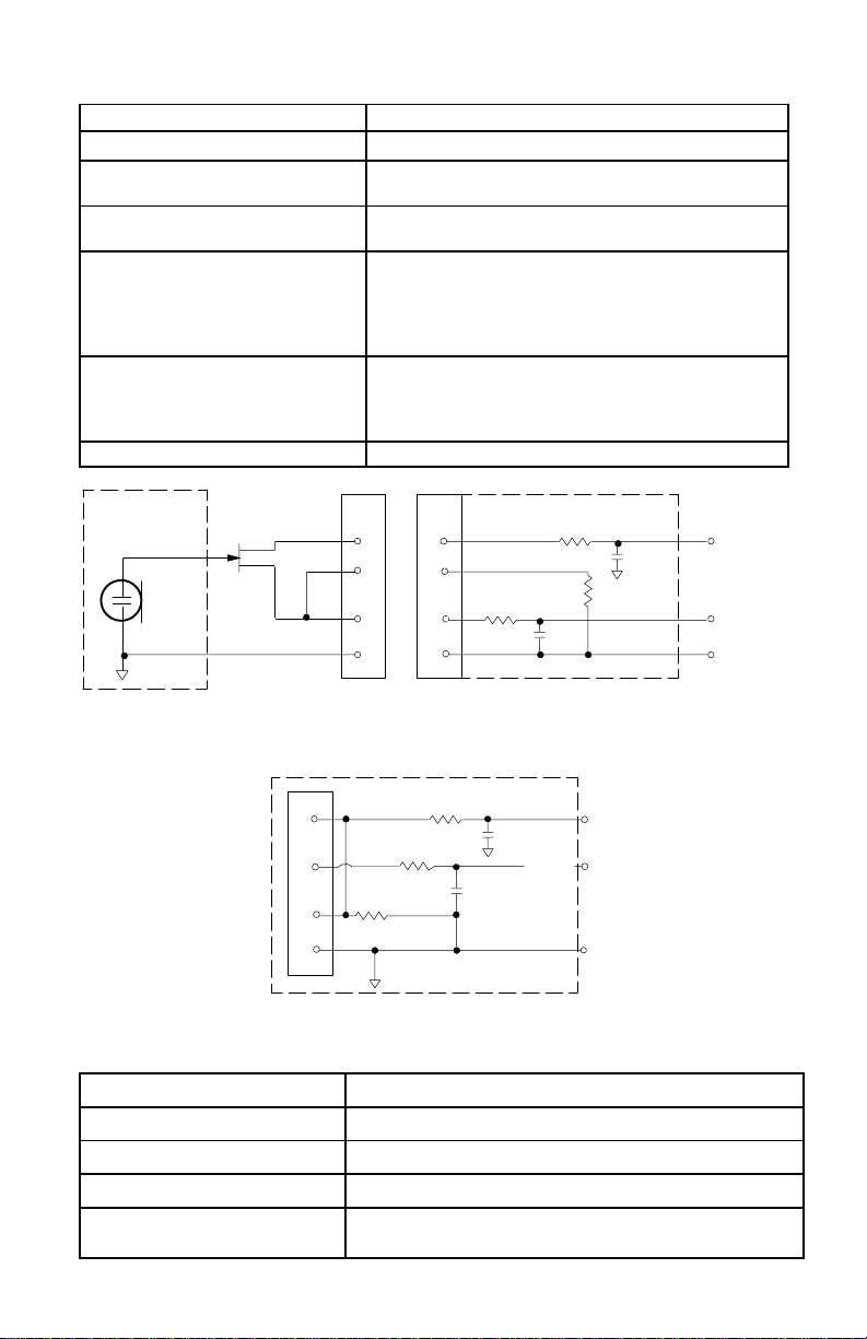
Entrée de l’émetteur U1 (Figure 1)
Connecteur : TA4F ou LEMO
Configuration de l’entrée : Asymétrique, active
Impédance réelle : 18 kW avec micro–cravate
Niveau d’entrée maximal : 6 V c–à–c (+7 dBV) pour 1 % DHT; gain
Affectation des broches
TA4F :
Affectation des broches LEMO
:
Tension d’alimentation
fantôme :
1 MW avec cordon d’instrument
minimal et signal de 1 kHz
Broche 1 : à Masse
Broche 2 : à +5 V
Broche 3 : à Audio
Broche 4 = 20 k à Masse et Audio (Sur le
cordon adaptateur d’instrument, la broche 4 est
flottante)
Broche 1 : à Broche 3 et 10 kW à Masse
Broche 2 : à +5 V
Broche 3 : à Broche 1
Broche 4 : à Blindage (Masse por biase positif)
+5V alimenté à la cartouche du microphone
MICROPHONE
ELEMENT
NOTE: LAVALIER MIC TIES PINS 3 AND 4
TOGETHER; GUITAR CABLE DOES NOT.
1
2
3
4
U1/ MIC JACK BOARD
2
2
4
4
500 Ω
3
3
499 Ω
1
499 Ω
AUDIO
27 pF
BIAS
27 pF
SHIELD
1
U1L (LEMO 4 PIN) MIC JACK BOARD
10K Ω
FIGURE 1
14
500 Ω
27 pF
20K Ω
27 pF
+5 V
AUDIO
GROUND
Page 15

Sortie de l’émetteur U1
Connecteur : Antenne
Impédance réelle : 50 Ω
Niveau de sortie nominal : +10 dBm
Niveau de sortie maximal : +11 dBm
Affectation des broches : Boîtier = Masse
Centre = Signal
Entrée de l’émetteur U2
Configuration de l’entrée : Asymétrique, active
Impédance réelle : 20 kΩ
Niveau d’entrée maximal : 3 V c–à–c (+0.5 dBV) pour 1 % DHT; gain minimal
et signal de 1 kHz
Sortie de l’émetteur U2
Connecteur : SMC
Impédance réelle : 50 Ω
Niveau de sortie nominal : +10 dBm
Niveau de sortie maximal : +11 dBm
Affectation des broches : Boîtier = Masse
Centre = Signal
Entrée des récepteurs U4S et U4D
Connecteur : Antenne Entrée secteur Interface
Type de connecteur : BNC CEI D 25 broches
Impédance réelle : 50 Ω –– ––
Niveau d’entrée nominal : –95 à –30 dBm 90 à 230 Vca,
50/60 Hz
réseau
Logique CMOS
Niveau d’entrée maximal :
Affectation des broches : Boîtier = Masse
Tension d’alimentatio
fantôme :
+6 dBm
(–20 dBm
recommand
Centre = Signal
12 V cc, 150
mA maximal
é)
15
230 V ca, 50/60
Hz
Norme CEI ––
–– ––
––
Page 16

Sortie des récepteurs U4S et U4D
Connecteur : Écouteurs de
Configuratio
n de la sortie
:
Impédance
réelle :
Niveau
d’entrée
nominal :
Affectation
des broches :
Protection
tension/
intensité/
alimentation
fantôme
*Niveau de sortie: mic = ligne – 30 dB
contrôle
Mono
asymétrique,
1/4 po
300 Ω –– 1 kΩ 30 Ω Voir
–– 90 à 230
Pointe = Sous
tension
Nuque = Sous
tension
Gaine =
Masse
Oui Oui Oui 5V, 700
Sortie
secteur
–– Asymétrique Symétrique Voir
Vca, 5 A
Norme
CEI
Audio à
haute
impédance
–– –– Logique
Pointe =
Sous
tension
Nuque/gain
e = Masse
Audio à
bass
impédance*
1 = Masse
2 = Sous
tension
3 = Sous
tension
Interface
réseau
annexe
annexe
CMOS
Voir
annexe
mA max.
Encombrement
U1 : 92,2 x 64,7 x 24,2 mm (L x Lr x P)
U2/58 : 254 x 50,8 mm (L x diam.)
U2/BETA 58A : 254 x 53,2 mm (L x diam.)
U2/87 : 228,6 x 49,2 mm (L x diam.)
U2/BETA 87 : 216 x 50,8 mm (L x diam.)
U4S/U4D : 44,5 x 482,6 x 295,3 mm (H x Lr x P)
Poids net
U1 : 175,2 g sans piles
U2/58, U2/BETA 58A : 375,6 g sans piles
U2/87, U2/BETA 87 : 303,1 g sans piles
U4S : 3,30 kg
U4D : 3,85 kg
Homologation
Les systèmes sans fil série UHF Shure sont conformes aux exigences
essentielles de la directive européenne R&TTE 99/5/CE et sont autorisés à
porter la marque CE.
U1, U2 : Conforme à la norme ETSI européenne EN 300 422 (parties 1 et 2) et
ETS 300 445/A1.
U4, U4D : Conforme à la norme ETSI européenne ETS 300 445/A1 et EN 60950.
CE MATÉRIEL RADIO EST PRÉVU POUR UTILISATION EN SPECTACLES
PROFESSIONNELS (CLASSE I) ET APPLICATIONS SIMILAIRES.
16
Page 17

ACCESSOIRES FOURNIS
Adaptateur de support de microphone (U2) WA371. . . . . . . . . . . . . . . . . . . . . . . . . . .
Pochette à fermeture éclair (U1) 26A13. . . . . . . . . . . . . . . . . . . . . . . . . . . . . . . . . . . . .
Pochette à fermeture éclair (U2) 26A14. . . . . . . . . . . . . . . . . . . . . . . . . . . . . . . . . . . . .
Tournevis 80A498. . . . . . . . . . . . . . . . . . . . . . . . . . . . . . . . . . . . . . . . . . . . . . . . . . . . . . .
Câble coaxial d’antenne (60 cm) UA802. . . . . . . . . . . . . . . . . . . . . . . . . . . . . . . . . . . . .
Antenne demi–onde (692 à 716 MHz) UA820B. . . . . . . . . . . . . . . . . . . . . . . . . . . . . . .
Valise de transport pour l’émetteur 65A8257. . . . . . . . . . . . . . . . . . . . . . . . . . . . . . . . .
Insertion de valise de transport 29B1577. . . . . . . . . . . . . . . . . . . . . . . . . . . . . . . . . . . .
ACCESSOIRES EN OPTION
Cordon adaptateur d’instrument (U1) WA302. . . . . . . . . . . . . . . . . . . . . . . . . . . . . . . . .
Connecteur femelle 4 broches TA4F (U1) WA33. . . . . . . . . . . . . . . . . . . . . . . . . . . . . .
Commutateur audio en ligne (U1) WA360. . . . . . . . . . . . . . . . . . . . . . . . . . . . . . . . . . . .
Câble d’interface récepteur–mélangeur de 1,80 m (fiche
téléphonique 1/4 po et fiche XLR) WA410. . . . . . . . . . . . . . . . . . . . . . . . . . . . . . . . . . . .
Rallonge d’antenne de 7,6 m UA825. . . . . . . . . . . . . . . . . . . . . . . . . . . . . . . . . . . . . . . .
Rallonge d’antenne de 30,4 m UA8100. . . . . . . . . . . . . . . . . . . . . . . . . . . . . . . . . . . . . .
Rallonge d’antenne de 15,2 m UA850. . . . . . . . . . . . . . . . . . . . . . . . . . . . . . . . . . . . . . .
Kit d’antenne active à distance en ligne (692–716 MHz) UA830UB. . . . . . . . . . . . .
Système répartiteur d’antennes/alimentation, 230 Vca UA845–UB. . . . . . . . . . . . . .
Antenne directionelle UA870UB. . . . . . . . . . . . . . . . . . . . . . . . . . . . . . . . . . . . . . . . . . .
PIÈCES DE RECHANGE
Kit d’installation (tournevis, pieds, serre–câbles) 90VL1371. . . . . . . . . . . . . . . . . . . .
Adaptateurs de montage des antennes à l’avant 95A8647. . . . . . . . . . . . . . . . . . . . .
Cordon d’alimentation 230 Vca 95A8247. . . . . . . . . . . . . . . . . . . . . . . . . . . . . . . . . . . .
Cordon d’alimentation en série 304 mm (230 V) 85A8678. . . . . . . . . . . . . . . . . . . . .
Cartouche SM58
Cartouche BETA 58A avec grille (U2/BETA 58) R179. . . . . . . . . . . . . . . . . . . . . . . . .
Cartouche SM87 avec grille (U2/87) R165. . . . . . . . . . . . . . . . . . . . . . . . . . . . . . . . . .
Cartouche BETA 87A avec grille (U2/BETA 87) R166. . . . . . . . . . . . . . . . . . . . . . . . .
Cartouche BETA 87C avec grille (U2/BETA 87) RPW100. . . . . . . . . . . . . . . . . . . . . .
Grille argent mat (U2/58) RK143G. . . . . . . . . . . . . . . . . . . . . . . . . . . . . . . . . . . . . . . . . .
Grille argent mat (U2/BETA 58) RK265G. . . . . . . . . . . . . . . . . . . . . . . . . . . . . . . . . . . . .
Grille argent mat (U2/BETA 87) RK313G. . . . . . . . . . . . . . . . . . . . . . . . . . . . . . . . . . . . .
Grille noire (U2/87) RK214G. . . . . . . . . . . . . . . . . . . . . . . . . . . . . . . . . . . . . . . . . . . . . . .
Grille noire (U2/BETA 58) RK323G. . . . . . . . . . . . . . . . . . . . . . . . . . . . . . . . . . . . . . . . . .
Grille noire (U2/BETA 87) RK324G. . . . . . . . . . . . . . . . . . . . . . . . . . . . . . . . . . . . . . . . . .
Pince de ceinture (U1) 53A8247A. . . . . . . . . . . . . . . . . . . . . . . . . . . . . . . . . . . . . . . . . .
Antenne (U1) 95A8646. . . . . . . . . . . . . . . . . . . . . . . . . . . . . . . . . . . . . . . . . . . . . . . . . . .
Antenne (U2) 95A2029. . . . . . . . . . . . . . . . . . . . . . . . . . . . . . . . . . . . . . . . . . . . . . . . . . .
avec grille (U2/58) R158. . . . . . . . . . . . . . . . . . . . . . . . . . . . . . . . .
RENSEIGNEMENTS SUR L’OCTROI DE LICENCE
Tout changement ou modification n’ayant pas fait l’objet d’une autorisation expresse de
Shure Incorporated peut entraîner la n ullité du droit d’utilisation de l ’équipem ent. L a l icen-
ce d’utilisation de l’équipement du microphone sans fil Shure demeure la responsabilité
de l’utilisateur , e t elle d épend de la classification de l’utilisateur et de l’application p révue
par lui ainsi que de la fréquence sélectionnée. S hure recommande v ivement de se mettre
en rapport avec les autorités compétentes des télécom m unications pour l ’obtention des
autorisations nécessaires, ainsi qu’avant de choisir et de commander des fr équences.
17
Page 18

INFORMATIONS DE CONFORMITÉ R&TTE
IMPORT ANT ! Les transmetteurs modèles Shure U1 et U2 conforme aux exigences
essentielles de la directive européenne R&TTE 99/5/CE et sont autorisés à porter la
marque CE.
Le recepteur modèle Shure U4 conforme aux exigences essentielles de la directive
européenne R&TTE 99/5/CE et sont autorisés à porter la marque CE.
CE MATÉRIEL RADIO EST PRÉVU POUR UTILISATION EN SPECTACLES PROFESSIONNELS ET APPLICATIONS SIMILAIRES.
REMARQUE : IL EST POSSIBLE QUE CE MATÉRIEL SOIT CAPABLE DE FONCTIONNER SUR CERTAINES FRÉQUENCES NON AUTORISÉES LOCALEMENT.
SE METTRE EN RAPPORT AVEC LES AUTORITÉS COMPÉTENTES POUR OB-
TENIR LES INFORMATIONS SUR LES FRÉQUENCES AUTORISÉES POUR LES
SYSTÈMES DE MICROPHONES SANS FIL LOCALEMENT
Autorisation d’utilisation : Noter qu’une licence officielle d’utilisation de ce matériel
peut être requise dans certains endroits. Consulter les autorités compétentes pour les
spécifications possibles.
Les modèles d’transmetteur Shu re U1 et U 2 peuvent être utilisés dans les pays et a ux
gammes de fréquences indiqués au Tableau 1.
Code de Pays U1-M3, U2-M3
A 692–716 MHz* 774–782 MHz* 782–810 MHz* 800–820 MHz* 800–830 MHz* 838–862 MHz*
B 692–716 MHz* 774–782 MHz* 782–810 MHz* 800–820 MHz* 800–830 MHz* 838–862 MHz*
CH 692–716 MHz* 774–782 MHz* 782–810 MHz* 800–820 MHz* 800–830 MHz* 838–862 MHz*
D 692–716 MHz* 774–782 MHz* 782–810 MHz* 800–820 MHz* 800–830 MHz* 838–862 MHz*
E 692–716 MHz* 774–782 MHz* 782–810 MHz* 800–820 MHz* 800–830 MHz* 838–862 MHz*
F 692–716 MHz* 774–782 MHz* 782–810 MHz* 800–820 MHz* 800–830 MHz* *
GB 692–716 MHz* 774–782 MHz* 782–810 MHz* * * 838–862 MHz*
GR 692–716 MHz* 774–782 MHz* 782–810 MHz* 800–820 MHz* 800–830 MHz* 838–862 MHz*
I 692–716 MHz* 774–782 MHz* 782–810 MHz* * * *
IRL 692–716 MHz* 774–782 MHz* 782–810 MHz* 800–820 MHz* 800–830 MHz* 838–862 MHz*
L 692–716 MHz* 774–782 MHz* 782–810 MHz* 800–820 MHz* 800–830 MHz* 838–862 MHz*
NL 692–716 MHz* 774–782 MHz* 782–810 MHz* 800–820 MHz* 800–830 MHz* 838–862 MHz*
P 692–716 MHz* 774–782 MHz* 782–810 MHz* 800–820 MHz* 800–830 MHz* 838–862 MHz*
DK * * 800–810 MHz* 800–820 MHz* 800–830 MHz* *
FIN * * 800,1–810
N * * 800–810 MHz* 800–820 MHz* 800–830 MHz* *
S * * 800–810 MHz* 800–814 MHz* 800–814 MHz* *
Tous les
autres pays
*Se mettre en rapport avec les autorités compétentes pour obtenir les informations sur les fréquences autorisées disponibles localement et sur l’utilisation autorisée du matériel.
REMARQUE : Shure recommande de maintenir une séparation de 500 kHz entre chaque
canal de récepteur dans les récepteurs à canal double U4D. Ne pas hésiter à contacter le
service clientèle de Shure (49-7131-72140) pour toute assistance ou informations complé-
mentaires concernant la sélection et le réglage des fréquences.
O682
TABLEAU 1
(692 - 716
MHz)
* * * * * *
U1-R3, U2-R3
(774 - 782
MHz)
U1-R7, U2-R7
(782 - 810
MHz)
MHz*
U1-R6, U2-R6
(800 - 820
MHz)
800,1–819,9
MHz*
U1-R2, U2-R2
(800 - 320
MHz)
800,1–819,9
MHz*
U1-S2, U2-S2
(838 - 862
MHz)
*
18
Page 19

GUIDE DE COMPATIBILITÉ DU SYSTÈME SANS FIL M3 UHF
Le tableau suivant donne une liste générale des systèmes compatibles en fréquence
dans la bande de 692,000 à 716,000 MHz. Chaque groupe comprend plusieurs canaux compatibles les uns avec les autres.
Jusqu’à 20 systèmes sans fil UHF Shure peuvent être utilisés simultanément dans la
bande de 692 à 716 MHz si ces systèmes sont de versions de fréquence UB (aban-
données) ou d’une combinaison de versions UB et M3. Jusqu’à 30 systèmes sans fil
MK2 UHF Shure peuvent être utilisés simultanément dans la bande de 692 à 716 MHz
s’ils sont tous de versions de fréquence M3.
Remarque : Les combinaisons d’émetteurs UHF Shure et de récepteurs MK2 UHF
Shure ainsi que les combinaisons d’émetteurs MK2 UHF Shure et de récepteurs UHF
Shure NE SONT PAS censées fonctionner. Toujours utiliser les combinaisons émetteurs–récepteurs de même version de fréquence (M3 ou UB).
Les groupes 1 à 16 DOIVENT être utilisés si l’installation comprend des systèmes
sans fil UHF Shure (fréquence UB seulement) ou des systèmes sans fil UHF Shure
et des systèmes sans fil MK2 UHF Shure (fréquences UB et M3)
Les groupes 1 à 16 PEUVENT être utilisés si l’installation comprend des systèmes
sans fil MK2 UHF Shure seulement (versions de fréquence M3).
Les groupes 17 à 27 peuvent UNIQUEMENT être utilisés si l’installation comprend
des systèmes sans fil MK2 UHF Shure seulement (versions de fréquence M3).
COMPOSANTS DES GROUPES
Groupes 1 à 10*
Les groupes 1 à 3 offrent le nombre maximum de fréquences compatibles entre 692
et 716 MHz.
Le groupe 4 o ffre l e n ombre m axim um d e f réquences compatibles entre 6 92 e t 7 16 M Hz.
Les groupes 5 à 6 offrent le nombre maximum de fréquences compatibles entre 692
et 716 MHz.
Le groupe 7 o ffre l e n ombre m axim um d e f réquences compatibles entre 6 92 e t 7 16 MHz.
Les groupes 8 à 10 offrent le nombre maximum de fréquences compatibles entre 692 et
716 MHz listées en ordre descendant.
Groupes 11 à 16*
Les groupes 11 à 12 sont conformes aux réglementations françaises pour le groupe
d’utilisateurs A.
Les groupes 13 à 14 sont conformes aux réglementations françaises pour le groupe
d’utilisateurs B.
Les groupes 15 à 16 sont conformes aux réglementations françaises pour le groupe
d’utilisateurs C.
Groupes 17 à 27*
Les groupes 17 à 18 o ffrent le nombre maximum de fréquences compatibles entre 692
et 716 MHz.
Les groupes 19 à 20 sont conformes aux réglementations françaises pour le groupe
d’utilisateurs A.
Les groupes 21 à 22 sont conformes aux réglementations françaises pour le groupe
d’utilisateurs B.
Les groupes 23 à 24 sont conformes aux réglementations françaises pour le groupe
d’utilisateurs C.
Les groupes 25 à 26 sont conformes aux réglementations allemandes pour les utilisateurs de diffusion.
Le groupe 27 est conforme aux réglementations belges p our l es utilisateurs de diffusion.
*Se mettre en rapport avec les autorités compétentes pour obtenir les informations sur les
fréquences autorisées disponibles localement et sur l’utilisation autorisée du matériel.
19
Page 20

TABLEAU 2
SYSTÈMES COMPATIBLES EN FRÉQUENCE DANS LA BANDE M3
(692–716 MHz)
Channel Groupe 1 Groupe 2 Groupe 3 Groupe 4 Groupe 5 Groupe 6 Groupe 7 Groupe 8
1 692.500 692.125 692.250 698.250 692.500 692.125 692.125 715.625
2 693.375 692.625 695.125 698.875 693.250 693.500 693.125 714.625
3 694.500 693.375 695.875 700.000 694.250 694.125 693.625 714.000
4 695.000 694.375 697.125 700.625 695.000 695.125 694.625 713.125
5 697.000 695.125 698.625 701.500 695.500 695.750 695.875 712.000
6 698.000 698.875 699.875 702.000 696.250 697.000 696.500 710.250
7 699.250 699.375 700.625 702.750 697.250 697.750 697.875 708.125
8 699.750 700.625 701.625 703.750 698.000 699.125 698.875 707.625
9 702.875 703.125 702.375 704.375 704.500 700.125 700.500 706.750
10 703.750 704.625 703.625 709.000 706.000 701.625 701.500 706.250
11 705.500 706.375 704.375 709.500 706.750 702.250 703.375 703.625
12 707.500 707.125 708.375 710.250 707.250 710.125 703.875 702.625
13 708.500 707.625 709.375 711.250 708.750 710.625 705.875 701.875
14 709.000 708.375 709.875 711.875 709.500 711.500 706.875 699.875
15 709.750 710.875 710.750 712.750 711.250 712.125 707.625 696.375
16 710.250 711.500 711.875 713.250 712.000 713.125 708.125 695.875
17 712.750 712.500 713.375 714.000 713.250 713.875 709.125 694.625
18 713.750 713.125 714.125 715.000 714.250 714.375 709.625 693.750
19 714.500 714.375 714.625 715.625 715.000 715.250 692.375
20 715.500 715.125 715.625 716.000 715.875
21
22
23
24
25
26
27
28
29
30
UB/M3 UB/M3 UB/M3 UB/M3 UB/M3 UB/M3 UB/M3 UB/M3
20
Page 21

Channel Groupe 9 Groupe 10 Groupe 11 Groupe 12 Groupe 13 Groupe 14 Groupe 15 Groupe 16
1 715.500 715.125 692.250 715.500 692.500 714.975 692.000 716.000
2 714.250 714.125 695.250 714.500 693.300 712.775 692.700 714.775
3 712.750 713.625 695.750 713.250 694.500 712.025 694.300 712.975
4 712.000 711.875 697.250 712.500 696.025 709.700 695.000 712.225
5 710.875 711.125 698.500 711.500 696.775 708.500 696.225 710.300
6 710.375 709.875 699.500 710.750 698.225 706.225 696.975 709.100
7 708.250 709.000 700.250 707.750 701.700 702.500 700.000 703.000
8 707.125 708.375 702.750 707.250 702.500 701.700 700.700 701.900
9 704.125 707.375 703.500 705.750 706.225 701.300 706.775 700.000
10 702.500 706.625 704.500 705.250 708.500 698.225 709.100 698.775
11 700.625 705.125 705.750 704.500 709.300 696.775 710.300 696.225
12 699.000 700.875 707.250 703.500 709.700 696.025 711.000 695.000
13 698.125 700.000 707.750 699.500 712.775 694.500 712.225 694.300
14 697.625 699.375 710.750 698.500 713.500 693.300 714.775 692.700
15 695.875 697.625 711.500 697.750 714.975 692.500 716.000 692.000
16 694.875 696.875 712.500 695.250
17 694.375 696.375 714.500 694.750
18 693.250 694.625 715.500 692.250
19 692.500 694.125
20 693.125
21
22
23
24
25
26
27
28
29
30
UB/M3 UB/M3 UB/M3 UB/M3 UB/M3 UB/M3 UB/M3 UB/M3
21
Page 22

Channel Groupe 17 Groupe 18 Groupe 19 Groupe 20 Groupe 21 Groupe 22 Groupe 23 Groupe 24
1 692.875 692.275 692.250 715.500 693.300 714.975 693.100 714.775
2 693.625 693.025 695.750 714.500 693.700 712.025 693.900 712.975
3 694.675 694.075 697.250 713.250 694.500 710.100 694.300 712.225
4 695.575 694.975 697.750 712.500 696.775 709.700 695.000 709.900
5 696.025 695.425 698.500 711.500 698.225 708.900 698.025 709.100
6 696.925 696.325 699.500 710.750 700.500 708.500 698.775 708.700
7 697.675 697.075 700.250 707.750 700.900 706.225 700.000 708.000
8 698.125 697.525 703.500 707.250 702.100 704.775 700.700 704.225
9 698.875 698.275 704.500 705.750 702.500 701.700 702.300 702.300
10 699.475 698.875 705.250 705.250 706.975 700.900 708.000 700.700
11 699.925 699.325 705.750 703.500 708.900 698.975 708.700 700.000
12 700.525 699.925 707.250 699.500 709.300 698.225 709.100 698.775
13 701.425 700.825 707.750 698.500 710.100 696.775 709.900 698.025
14 701.875 701.275 710.750 697.750 712.025 696.025 712.225 695.000
15 702.775 702.175 711.500 696.500 712.775 694.100 712.975 694.300
16 704.575 703.975 712.500 695.750 714.225 692.500 714.025 693.900
17 705.775 705.175 714.500 694.750 714.775 693.100
18 707.575 706.975 715.500 692.250
19 708.475 707.875
20 708.925 708.325
21 709.825 709.225
22 710.425 709.825
23 711.325 710.725
24 711.775 711.175
25 712.525 711.925
26 712.975 712.375
27 714.025 713.425
28 714.775 714.175
29 715.375 714.775
30 715.825 715.225
M3 M3 M3 M3 M3 M3 M3 M3
22
Page 23

Channel Groupe 25 Groupe 26 Groupe 27
1 692.150 692.600 710.150
2 692.600 692.975 710.600
3 694.000 694.450 710.900
4 694.900 695.125 711.500
5 695.650 695.575 711.800
6 696.100 696.550 712.250
7 697.000 697.075 713.300
8 697.450 698.350 714.200
9 698.050 698.875 714.650
10 698.500 699.175 714.950
11 699.400 699.850 715.475
12 699.850 700.300 715.850
13 704.250 704.325
14 705.000 705.975
15 705.450 706.575
16 706.800 707.325
17 707.400 708.525
18 708.300 710.075
19 710.900 710.825
20 711.350 711.425
21 712.100 711.800
22 712.700 712.475
23 713.150 713.750
24 714.650 714.650
25 715.700 715.250
26
27
28
29
30
M3 M3 M3
23
Page 24

SPEZIFIKATIONEN
Frequenzbereich
692–716 MHz
Reichweite
150 m Minimum unter Normalbedingungen; 500 m maximal.
HINWEIS: Die tatsächliche Reichweite hängt von der HF-Signalabsorption,
-reflexio n und -interferenz ab.
Audiofrequenzgang
50 bis 15,000 Hz, "2 dB.
HINWEIS: Der Gesamtaudiofrequenzgang des Systems hängt vom
Mikrophonelement ab.
Verstärkungsbereich
U1: 0 bis 40 dB
U2: 0 bis 26 dB
Modulation
"18 kHz Komprimierungs–/Dekomprimierungssystem mit Preemphasis und
Deemphasis.
Dynamikbereich
>102 dB, mit A–Bewertung
HF–Empfindlichkeit:
U4S U4D
–110 dBm
12 dB SINAD
–105 dBm
30 dB SINAD
–107 dBm
12 dB SINAD
–102 dBm
30 dB SINAD
HF–Leistungsabgabe
U1, U2: maximal 10 mW
Spiegelselektion
90 dB (typisch)
Oberwellenunterdrückung
75 dB (typisch)
Grenzschalldämmung (bzgl. 45 kHz Abweichung)
>100 dB, mit A–Bewertung
Audiopolarität
Positiver Druck auf die Mikrophonmembran (oder positive Spannung an der
Spitze des Klinkensteckers WA302) erzeugt positive Spannung an Pin 2
hinsichtlich Pin 3 des Niederimpedanzausgangs und der Spitze des
Hochimpedanz–6,3mm–Ausgangs.
Systemverzerrung (bzgl. "18 kHz Abweichung, 1 kHz Modulation)
0,3% Gesamtklirrfaktor (typisch)
Stromversorgung
U1, U2: 1,5–V–Alkalibatterie (Duracell MN 1500 wird empfohlen), wahlweise NiCd
U4: 230 V Wechselstrom, 50/60 Hz
Leistungsaufnahme: 9.6 W min, 13.2 W max (U4S)
12 W min, 16 W max (U4D)
15 W min, 16 W max (UA845)
24
Page 25

Batterielebensdauer Sender (typisch)
12 Stunden (für Duracell MN 1500 1,5–V–Alkalibatterien)
Betriebstemperaturbereich
–6_ bis +49_ C
HINWEIS: Batterieeigenschaften können diesen Bereich einschränken.
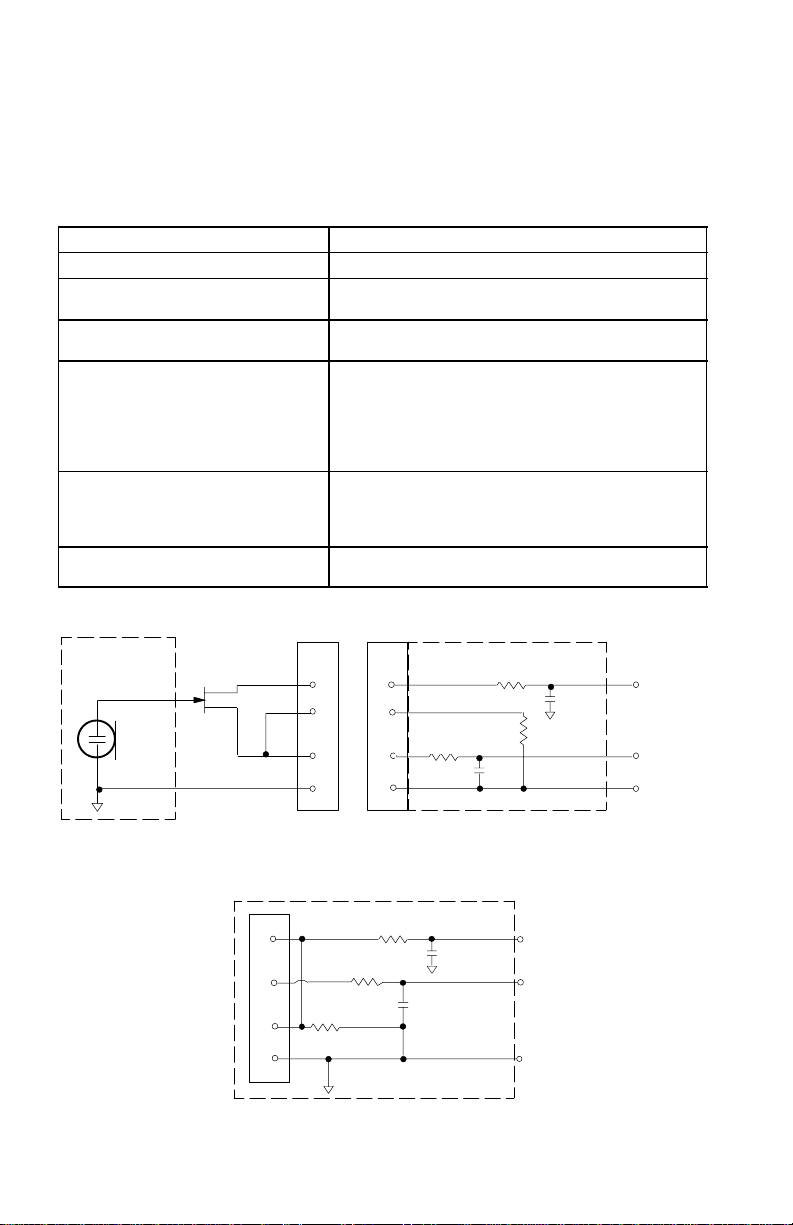
U1–Sendereingang (Abbildung 1)
Anschluß: TA4F oder LEMO
Eingangskonfiguration: Asymmetrisch, aktiv
Tatsächliche Impedanz:
Maximaler Eingangs-pegel: 6 Vss (+7 dBV) für 1% Gesamtklirrfaktor bei
minimaler Verstärkungseinstellung mit 1 kHz Signal
TA4F
Pinkonfiguration:
Instrumentenadapterkabeln ist Pin 4 nicht geerdet)
LEMO Pinkonfiguration: Pin 1: an Pin 3 und 10 kΩ an Erdung
Spannung für
Phantomspeisung:
18 k Bei Lavalier–Mikrophon
1M mit Instrumentenkabel
Pin 1: Erdung
Pin 2: +5V
Pin 3: Audio
Pin 4 : an 20 kΩ für Erdung & Audio (bei
Pin 2: +5V
Pin 3: Pin 1
Pin 4: an der Schirmung (Erdung)
+5 V Versorgung an Mikrophonkapsel
MIKROPHON
ELEMENT
HINWEIS: DAS LAVALIERKABEL VERBINDET Pin 3 UND 4; DAS
GITARRENKABEL ERFÜLLT DIESE FUNKTION NICHT
U1L (LEMO–4 POLIG) MIKROFONBUCHSE
1
2
3
4
2
4
3
1
499 Ω
499 Ω
10K Ω
U1 MIKROPHON–KLINKENPLATTE
2
4
500 Ω
3
1
AUDIO
27 pF
VORSPANNUNG
27 pF
ABSCHIRMUNG
ABBILDUNG 1
25
500 Ω
27 pF
20K Ω
27 pF
+5 V
AUDIO
ERDUNG
Page 26

U1–Senderausgang (Abbildung 1)
Anschlußtyp: SMC
Tatsächliche Impedanz:
Nominaler Ausgangs pegel: +10 dBm
Maximaler Ausgangs pegel: +11 dBm
Pinkonfiguration: Mantel = Erdung
50
Mitte = Signal
U2–Sendereingang
Eingangskonfiguration: Asymmetrisch, aktiv
Tatsächliche Impedanz:
MaximaleR Eingangspegel: 3 Vss (+0.5 dBV) für 1% Gesamtklirrfaktor bei
minimaler Verstärkungseinstellung und
20 K
1–kHz–Signal
U2–Senderausgang
Anschlußtyp: SMC
Tatsächliche Impedanz:
Nominaler Ausgangspegel: +10 dBm
Maximaler Ausgangspegel: +11 dBm
Pinkonfiguration: Mantel = Erdung
50
Mitte = Signal
U4S– und U4D–Empfängereingang
Anschluß: Antenne Netzeingang Netzschnittstelle
Anschlußtyp: BNC CEI 320 25–polig D
Tatsächliche
Impedanz:
Nominaler
Eingangspegel:
50 Ω –– ––
–95 bis –30 dBm 230 V
Wechselstrom
50/60 Hz
CMOS–Logik
Maximaler
Eingangspegel:
Pinkonfiguration:Mantel = Erdung
Spannung für
Remote
speisung:
+6 dBm
(–20 dBm
empfohlen)
Mitte = Signal
12 V , 150 mA
max.
254 V
Wechselstrom,
50/60 Hz
IEC–Standard ––
–– 5 V, 700 mA max.
26
––
Page 27

U4S– und U4D–Empfängerausgang
Anschluß: Monitor–
Ausgangs–
konfiguratio
n:
Tatsächliche
Impedanz:
Nominaler
Eingang–
spegel:
Pinkon–
figuration:
Spannungs–/
Strom–/
Phantom–
speisungs–
schutz?
*Mikrofonpegel = Linepegel –30 dB
ausgsng
Asymmetrisch
Mono,
6,3mm–Klinke
300 Ω –– 1 kΩ 30 Ω siehe
–– 230 V
Spitze = unter
Spannung
tension
Ring = unter
Spannung
Hülse =
Erdung
Ja Ja Ja ––
Strom-
ausgang
–– Asymme–
Wechsel
strom,
5A
IEC
Standar
d
Z–Audio
Spitze =
Spannung
Ring/Hüls
High
trisch
–– –– CMOS–
unter
e =
Erdung
Low
Z–Audio*
Symme-
trisch
1 = Erdung
2 = unter
Spannung
3 = unter
Spannung
schnittstel-
Anhang
Anhang
Anhang
Netz-
le
siehe
Logik
siehe
Gesamtabmessungen
U1, H x B x T: 92,2 mm x 64,7 mm x 24,2 mm
U2/58, L x Durchmesser: 254 mm x 50,80 mm
U2/BETA 58A, L x Durchmesser: 254 mm x 53,2 mm
U2/87, L x Durchmesser: 228,6 mm x 49,2 mm
U2/BETA 87, L x Durchmesser: 216 mm x 50,8 mm
U4S/U4D: H x B x T: 44,5 mm x 482,6 mm x 295,3 mm
Nettogewicht
U1: 175,2 g ohne Batterien
U2/58, U2/BETA 58A: 375,6 g ohne Batterien
U2/87, U2/BETA 87: 303,1 g ohne Batterien
U4S: 3,3 kg
U4D: 3,85 kg
Zulassung
Die Drahtlossysteme der Serie Shure UHF entsprechen den Grundanforderungen
der europäischen R&TTE–Richtlinie 99/5/EC und sind zum Tragen des
CE–Zeichens berechtigt.
U1, U2: Entspricht der europäischen ETSI Norm EN 300 422, Teil 1 und 2, und
ETS 300 445/A1.
U4, U4D: Entspricht der europäischen ETSI Norm EN 300 445/A1 und EN 60950.
DIESES FUNKGERÄT IST ZUR VERWENDUNG IM
UNTERHALTUNGSGEWERBE (KLASSE I) UND IN ÄHNLICHEN
ANWENDUNGEN VORGESEHEN.
27
Page 28

MITGELIEFERTES ZUBEHÖR
Mikrofonstativadapter (U2) WA371. . . . . . . . . . . . . . . . . . . . . . . . . . . . . . . . . . . . . . . . . .
Tasche (U1) 26A13. . . . . . . . . . . . . . . . . . . . . . . . . . . . . . . . . . . . . . . . . . . . . . . . . . . . . .
Tasche (U2) 26A14. . . . . . . . . . . . . . . . . . . . . . . . . . . . . . . . . . . . . . . . . . . . . . . . . . . . . .
Schraubendreher 80A498. . . . . . . . . . . . . . . . . . . . . . . . . . . . . . . . . . . . . . . . . . . . . . . . .
Antennenkabel (60cm) UA802. . . . . . . . . . . . . . . . . . . . . . . . . . . . . . . . . . . . . . . . . . . . .
Halbwellenantenne (692–716 MHz) UA820B. . . . . . . . . . . . . . . . . . . . . . . . . . . . . . . .
Sendertragetasche 65A8257. . . . . . . . . . . . . . . . . . . . . . . . . . . . . . . . . . . . . . . . . . . . . .
Sendertragetasche Einsatzstück 29B1577. . . . . . . . . . . . . . . . . . . . . . . . . . . . . . . . . .
ZUSATZAUSRÜSTUNG
Instrumentenadapterkabel (U1) WA302. . . . . . . . . . . . . . . . . . . . . . . . . . . . . . . . . . . . . .
TA4F 4–polige Buchse (U1) WA330. . . . . . . . . . . . . . . . . . . . . . . . . . . . . . . . . . . . . . . . .
Inline–Audioschalter (U1) WA360. . . . . . . . . . . . . . . . . . . . . . . . . . . . . . . . . . . . . . . . . . .
1,8 m Empfänger–Mischpultkabel (6,3mm Klinken– an XLR–Anschluß) WA410. . .
7,6 m Antennenverlängerungskabel UA825. . . . . . . . . . . . . . . . . . . . . . . . . . . . . . . . . .
15,2 m Antennenverlängerungskabel UA850. . . . . . . . . . . . . . . . . . . . . . . . . . . . . . . . .
30,4 m Antennenverlängerungskabel UA8100. . . . . . . . . . . . . . . . . . . . . . . . . . . . . . . .
Inline–Antennenverstärker (692–716 MHz) UA830UB. . . . . . . . . . . . . . . . . . . . . . . . .
Antennen–/Stromverteilungssystem, 230 V Wechselstrom UA845–UB. . . . . . . . . .
Aktive UHF–Richtantenne UA870UB. . . . . . . . . . . . . . . . . . . . . . . . . . . . . . . . . . . . . . .
ERSATZTEILE
Beschlagteile (Schraubendreher, Montagefüßchen, Kabelklemmen) 90VL1371. . . . . .
Trennwandadapter für Frontantennen 95A8647. . . . . . . . . . . . . . . . . . . . . . . . . . . . . .
230 V Wechselstromkabel 95A8247. . . . . . . . . . . . . . . . . . . . . . . . . . . . . . . . . . . . . . .
304 mm Verkettungsstromkabel (230 V) 95A8678. . . . . . . . . . . . . . . . . . . . . . . . . . . .
Microfonkapsel SM58
Microfonkapsel BETA 58A mit Grill (U2/BETA 58) R179. . . . . . . . . . . . . . . . . . . . . . .
Microfonkapsel SM87 mit Grill (U2/87) R165. . . . . . . . . . . . . . . . . . . . . . . . . . . . . . . . .
Microfonkapsel BETA 87A mit Grill (U2/BETA 87) R166. . . . . . . . . . . . . . . . . . . . . . .
Microfonkapsel BETA 87C mit Grill (U2/BETA 87) RPW100. . . . . . . . . . . . . . . . . . . .
Grill Mattsilber (U2/58) RK143G. . . . . . . . . . . . . . . . . . . . . . . . . . . . . . . . . . . . . . . . . . . .
Grill Mattsilber (U2/BETA 58) RK265G. . . . . . . . . . . . . . . . . . . . . . . . . . . . . . . . . . . . . . .
Grill Mattsilber (U2/BETA 58) RK313G. . . . . . . . . . . . . . . . . . . . . . . . . . . . . . . . . . . . . . .
Grill Schwarz (U2/87) RK214G. . . . . . . . . . . . . . . . . . . . . . . . . . . . . . . . . . . . . . . . . . . . .
Grill Schwarz (U2/BETA58) RK323G. . . . . . . . . . . . . . . . . . . . . . . . . . . . . . . . . . . . . . . .
Grill Schwarz (U2/BETA 87) RK324G. . . . . . . . . . . . . . . . . . . . . . . . . . . . . . . . . . . . . . . .
Gürtelhalter (U1) 53A8247A. . . . . . . . . . . . . . . . . . . . . . . . . . . . . . . . . . . . . . . . . . . . . . .
Antenne (U1) 95A8646. . . . . . . . . . . . . . . . . . . . . . . . . . . . . . . . . . . . . . . . . . . . . . . . . . .
Antenne (U2) 95A2029. . . . . . . . . . . . . . . . . . . . . . . . . . . . . . . . . . . . . . . . . . . . . . . . . . .
mit Grill (U2/58) R158. . . . . . . . . . . . . . . . . . . . . . . . . . . . . . .
LIZENZINFORMATIONEN
Nicht ausdrücklich von Shure Incorporated genehmigte Änderungen oder Modifikatio-
nen können den Entzug der Betriebsgenehmigung für das Gerät zur Folge haben.
Das Erlangen einer Lizenz für drahtlose Shure–Mikrofonsysteme obliegt dem Benut-
zer. Die Erteilung einer Lizenz hängt von der Klassifizierung und Anwendung durch
den Benutzer sowie von der ausgewählten Frequenz ab. Shure empfiehlt dem Benut-
zer dringend, sich vor der Auswahl und Bestellung von Frequenzen mit der zuständi-
gen Fernmelde–/Regulierungsbehörde hinsichtlich der ordnungsgemäßen Zulassung
in Verbindung zu setzen.
28
Page 29

R&TTE–ÜBEREINSTIMMUNGSINFORMATIONEN
WICHTIG! Die Senders Modells U1 und U2 entsprechen den Grundanforderungen
der europäischen R&TTE–Richtlinie 99/5/EC und sind zum Tragen des CE–Zeichens
berechtigt.
Der Empfänger Modell U4 entsprechen den Grundanforderungen der europäischen
R&TTE–Richtlinie 99/5/EC und sind zum Tragen des CE–Zeichens berechtigt.
DIESES FUNKGERÄT IST ZUR VERWENDUNG IM UNTERHALTUNGSGEWERBE
UND IN ÄHNLICHEN ANWENDUNGEN VORGESEHEN.
HINWEIS: DIESES GERÄT KANN MÖGLICHERWEISE AUF EINIGEN FREQUEN-
ZEN ARBEITEN, DIE IN IHREM GEBIET NICHT ZUGELASSEN SIND. WENDEN
SIE SICH BITTE AN DIE ZUST ÄNDIGE BEHÖRDE, UM INFORMATIONEN ÜBER
ZUGELASSENE FREQUENZEN FÜR DRAHTLOSE MIKROFONPRODUKTE IN
IHREM GEBIET ZU ERHALTEN.
Zulassung: Es ist zu beachten, dass in einigen Gebieten für den Betrieb dieses Ge-
räts u.U. eine behördliche Zulassung erforderlich ist. Wenden Sie sich bitte an die zuständige Behörde, um Informationen über mögliche Anforderungen zu erhalten.
Die Shure-Sendermodelles U1 und U 2 k önnen in d en L ändern und m it d en F requenzberei-
chen verwendet werden, die in Tabelle 1 aufgeführt sind.
Lander–Kurzel U1-M3, U2-M3
A 692–716 MHz* 774–782 MHz* 782–810 MHz* 800–820 MHz* 800–830 MHz* 838–862 MHz*
B 692–716 MHz* 774–782 MHz* 782–810 MHz* 800–820 MHz* 800–830 MHz* 838–862 MHz*
CH 692–716 MHz* 774–782 MHz* 782–810 MHz* 800–820 MHz* 800–830 MHz* 838–862 MHz*
D 692–716 MHz* 774–782 MHz* 782–810 MHz* 800–820 MHz* 800–830 MHz* 838–862 MHz*
E 692–716 MHz* 774–782 MHz* 782–810 MHz* 800–820 MHz* 800–830 MHz* 838–862 MHz*
F 692–716 MHz* 774–782 MHz* 782–810 MHz* 800–820 MHz* 800–830 MHz* *
GB 692–716 MHz* 774–782 MHz* 782–810 MHz* * * 838–862 MHz*
GR 692–716 MHz* 774–782 MHz* 782–810 MHz* 800–820 MHz* 800–830 MHz* 838–862 MHz*
I 692–716 MHz* 774–782 MHz* 782–810 MHz* * * *
IRL 692–716 MHz* 774–782 MHz* 782–810 MHz* 800–820 MHz* 800–830 MHz* 838–862 MHz*
L 692–716 MHz* 774–782 MHz* 782–810 MHz* 800–820 MHz* 800–830 MHz* 838–862 MHz*
NL 692–716 MHz* 774–782 MHz* 782–810 MHz* 800–820 MHz* 800–830 MHz* 838–862 MHz*
P 692–716 MHz* 774–782 MHz* 782–810 MHz* 800–820 MHz* 800–830 MHz* 838–862 MHz*
DK * * 800–810 MHz* 800–820 MHz* 800–830 MHz* *
FIN * * 800,1–810
N * * 800–810 MHz* 800–820 MHz* 800–830 MHz* *
S * * 800–810 MHz* 800–814 MHz* 800–814 MHz* *
Alle anderen
Länder
*Für Informationen bezüglich der für Ihr Gebiet verfügbaren gesetzlich zugelassenen Frequenzen und der gesetzlichen Bestimmungen für den Einsatz der Geräte setzen Sie sich bitte mit der
zuständigen örtlichen Behörde in Verbindung.
HINWEIS: Shure empfiehlt, 500 kHz Kanaltrennung zwischen jedem Empfängerkanal in den
2–Kanal–Empfängern U4D aufrecht zu erhalten. Wenn weitere Informationen oder Unterstützung bei der Frequenzauswahl und Einrichtung gewünscht werden, wenden Sie sich
bitte an die Kundendienstabteilung von Shure (49-7131-72140)
O682
TABELLE 1
(692 - 716
MHz)
* * * * * *
U1-R3, U2-R3
(774 - 782
MHz)
U1-R7, U2-R7
(782 - 810
MHz)
MHz*
U1-R6, U2-R6
(800 - 820
MHz)
800,1–819,9
MHz*
U1-R2, U2-R2
(800 - 320
MHz)
800,1–819,9
MHz*
U1-S2, U2-S2
(838 - 862
MHz)
*
29
Page 30

KOMPATIBILITÄTSLEITFADEN FÜR UHF–M3–DRAHTLOSSYSTEME
Tabelle 2 stellt eine praktische Übersicht über frequenzkompatible Systeme im Fre-
quenzbereich von 692.000 bis 716.000 MHz dar. Jede Gruppe enthält mehrere Kanäle, die alle miteinander kompatibel sind.
Bis zu 20 Shure UHF–Drahtlossysteme können gleichzeitig innerhalb des 692–716
MHz–Frequenzbereichs betrieben werden, wenn es sich bei den Systemen um UB–
Frequenzversionen (Produktion eingestellt) oder eine Kombination von UB– und
M3–Ausführungen handelt. Bis zu 30 Shure UHF–MK2–Drahtlossysteme können
gleichzeitig innerhalb des 692–716 MHz–Frequenzbereichs betrieben werden, wenn
alle Systeme M3–Frequenzausführungen sind.
Hinweis: Kombinationen von Shure UHF–Sendern und Shure UHF–MK2–Empfängern
und Kombinationen von Shure UHF–MK2–Sendern und Shure UHF–Empfängern sind
NICHT für d en g em einsamen E insatz vorgesehen. Es müssen stets Sender/Empfänger–
Kombinationen derselben Frequenzausführung (M3 oder UB) verwendet werden.
Gruppen 1–16 MÜSSEN verwendet werden, wenn folgende Systeme in der Installation vorhanden sind Shure UHF–Drahtlossysteme (nur UB–Frequenzausführungen)
oder Shure UHF–Drahtlossysteme und Shure UHF–MK2–Drahtlossysteme (UB– und
M3–Frequenzausführungen).
Gruppen 1–16 K ÖNNEN verwendet w erden, wenn f olgende S ysteme in der Installation
vorhanden sind nur Shure UHF–MK2–Drahtlossysteme (M3–Frequenzausführungen).
Gruppen 17–27 können NUR verwendet werden, wenn folgende Systeme in der
Installation vorhanden sind nur Shure UHF–MK2–Drahtlossysteme (M3–Frequen-
zausführungen)
GRUPPENZUSAMMENSETZUNG
Gruppen 1–10*
Gruppen 1–3 bieten die maximale Anzahl kompatibler Frequenzen zwischen 692 und
716 MHz.
Gruppe 4 bietet d ie maximale A nzahl kompatibler Frequenzen z wischen 692 und 7 16 MHz.
Gruppen 5–6 bieten die maximale Anzahl kompatibler Frequenzen zwischen 692 und
716 MHz.
Gruppe 7 bietet d ie maximale A nzahl kompatibler Frequenzen z wischen 692 und 7 16 MHz.
Gruppen 8–10 bieten die maximale Anzahl kompatibler Frequenzen zwischen 692
und 716 MHz.
Gruppen 11–16*
Gruppen 11–12 entsprechen den französischen Verordnungen für Nutzergruppe A.
Gruppen 13–14 entsprechen den französischen Verordnungen für Nutzergruppe B.
Gruppen 15–16 entsprechen den französischen Verordnungen für Nutzergruppe C.
Gruppen 17–27*
Gruppen 17–27 bieten die maximale Anzahl kompatibler Frequenzen zwischen 692
und 716 MHz.
Gruppen 21–22 entsprechen den französischen Verordnungen für Nutzergruppe A.
Gruppen 23–24 entsprechen den französischen Verordnungen für Nutzergruppe B.
Gruppen 25–26 entsprechen den französischen Verordnungen für Nutzergruppe C.
Gruppen 25–26 entsprechen den deutschen Verordnungen für Rundfunknutzer.
Gruppe 27 entspricht den belgischen Verordnungen für Rundfunknutzer.
*Informationen über die an Ihren Standorten verfügbaren zulässigen Frequenzen und die
gesetzlichen Bestimmungen für den Einsatz der Geräte sind von der zuständigen örtlichen
Frequenzbehörde einzuholen.
30
Page 31

TABELLE 2
FREQUENZKOMPATIBLE SYSTEM E IM FREQUENZBEREICH M3
(692–716 MHz)
Kanal Gruppe 1 Gruppe 2 Gruppe 3 Gruppe 4 Gruppe 5 Gruppe 6 Gruppe 7 Gruppe 8
1 692.500 692.125 692.250 698.250 692.500 692.125 692.125 715.625
2 693.375 692.625 695.125 698.875 693.250 693.500 693.125 714.625
3 694.500 693.375 695.875 700.000 694.250 694.125 693.625 714.000
4 695.000 694.375 697.125 700.625 695.000 695.125 694.625 713.125
5 697.000 695.125 698.625 701.500 695.500 695.750 695.875 712.000
6 698.000 698.875 699.875 702.000 696.250 697.000 696.500 710.250
7 699.250 699.375 700.625 702.750 697.250 697.750 697.875 708.125
8 699.750 700.625 701.625 703.750 698.000 699.125 698.875 707.625
9 702.875 703.125 702.375 704.375 704.500 700.125 700.500 706.750
10 703.750 704.625 703.625 709.000 706.000 701.625 701.500 706.250
11 705.500 706.375 704.375 709.500 706.750 702.250 703.375 703.625
12 707.500 707.125 708.375 710.250 707.250 710.125 703.875 702.625
13 708.500 707.625 709.375 711.250 708.750 710.625 705.875 701.875
14 709.000 708.375 709.875 711.875 709.500 711.500 706.875 699.875
15 709.750 710.875 710.750 712.750 711.250 712.125 707.625 696.375
16 710.250 711.500 711.875 713.250 712.000 713.125 708.125 695.875
17 712.750 712.500 713.375 714.000 713.250 713.875 709.125 694.625
18 713.750 713.125 714.125 715.000 714.250 714.375 709.625 693.750
19 714.500 714.375 714.625 715.625 715.000 715.250 692.375
20 715.500 715.125 715.625 716.000 715.875
21
22
23
24
25
26
27
28
29
30
UB/M3 UB/M3 UB/M3 UB/M3 UB/M3 UB/M3 UB/M3 UB/M3
31
Page 32

Kanal Gruppe 9 Gruppe 10 Gruppe 11 Gruppe 12 Gruppe 13 Gruppe 14 Gruppe 15 Gruppe 16
1 715.500 715.125 692.250 715.500 692.500 714.975 692.000 716.000
2 714.250 714.125 695.250 714.500 693.300 712.775 692.700 714.775
3 712.750 713.625 695.750 713.250 694.500 712.025 694.300 712.975
4 712.000 711.875 697.250 712.500 696.025 709.700 695.000 712.225
5 710.875 711.125 698.500 711.500 696.775 708.500 696.225 710.300
6 710.375 709.875 699.500 710.750 698.225 706.225 696.975 709.100
7 708.250 709.000 700.250 707.750 701.700 702.500 700.000 703.000
8 707.125 708.375 702.750 707.250 702.500 701.700 700.700 701.900
9 704.125 707.375 703.500 705.750 706.225 701.300 706.775 700.000
10 702.500 706.625 704.500 705.250 708.500 698.225 709.100 698.775
11 700.625 705.125 705.750 704.500 709.300 696.775 710.300 696.225
12 699.000 700.875 707.250 703.500 709.700 696.025 711.000 695.000
13 698.125 700.000 707.750 699.500 712.775 694.500 712.225 694.300
14 697.625 699.375 710.750 698.500 713.500 693.300 714.775 692.700
15 695.875 697.625 711.500 697.750 714.975 692.500 716.000 692.000
16 694.875 696.875 712.500 695.250
17 694.375 696.375 714.500 694.750
18 693.250 694.625 715.500 692.250
19 692.500 694.125
20 693.125
21
22
23
24
25
26
27
28
29
30
UB/M3 UB/M3 UB/M3 UB/M3 UB/M3 UB/M3 UB/M3 UB/M3
32
Page 33

Kanal Gruppe 17 Gruppe 18 Gruppe 19 Gruppe 20 Gruppe 21 Gruppe 22 Gruppe 23 Gruppe 24
1 692.875 692.275 692.250 715.500 693.300 714.975 693.100 714.775
2 693.625 693.025 695.750 714.500 693.700 712.025 693.900 712.975
3 694.675 694.075 697.250 713.250 694.500 710.100 694.300 712.225
4 695.575 694.975 697.750 712.500 696.775 709.700 695.000 709.900
5 696.025 695.425 698.500 711.500 698.225 708.900 698.025 709.100
6 696.925 696.325 699.500 710.750 700.500 708.500 698.775 708.700
7 697.675 697.075 700.250 707.750 700.900 706.225 700.000 708.000
8 698.125 697.525 703.500 707.250 702.100 704.775 700.700 704.225
9 698.875 698.275 704.500 705.750 702.500 701.700 702.300 702.300
10 699.475 698.875 705.250 705.250 706.975 700.900 708.000 700.700
11 699.925 699.325 705.750 703.500 708.900 698.975 708.700 700.000
12 700.525 699.925 707.250 699.500 709.300 698.225 709.100 698.775
13 701.425 700.825 707.750 698.500 710.100 696.775 709.900 698.025
14 701.875 701.275 710.750 697.750 712.025 696.025 712.225 695.000
15 702.775 702.175 711.500 696.500 712.775 694.100 712.975 694.300
16 704.575 703.975 712.500 695.750 714.225 692.500 714.025 693.900
17 705.775 705.175 714.500 694.750 714.775 693.100
18 707.575 706.975 715.500 692.250
19 708.475 707.875
20 708.925 708.325
21 709.825 709.225
22 710.425 709.825
23 711.325 710.725
24 711.775 711.175
25 712.525 711.925
26 712.975 712.375
27 714.025 713.425
28 714.775 714.175
29 715.375 714.775
30 715.825 715.225
M3 M3 M3 M3 M3 M3 M3 M3
33
Page 34

Kanal Gruppe 25 Gruppe 26 Gruppe 27
1 692.150 692.600 710.150
2 692.600 692.975 710.600
3 694.000 694.450 710.900
4 694.900 695.125 711.500
5 695.650 695.575 711.800
6 696.100 696.550 712.250
7 697.000 697.075 713.300
8 697.450 698.350 714.200
9 698.050 698.875 714.650
10 698.500 699.175 714.950
11 699.400 699.850 715.475
12 699.850 700.300 715.850
13 704.250 704.325
14 705.000 705.975
15 705.450 706.575
16 706.800 707.325
17 707.400 708.525
18 708.300 710.075
19 710.900 710.825
20 711.350 711.425
21 712.100 711.800
22 712.700 712.475
23 713.150 713.750
24 714.650 714.650
25 715.700 715.250
26
27
28
29
30
M3 M3 M3
34
Page 35

ESPECIFICACIONES
Gama de frecuencias portadoras
692–716 MHz
Alcance
152,4 m mínimo, bajo condiciones típicas; 487.6 m máximo.
NOT A: El alcance real depende de los niveles de absorción, reflexión e interferencia
de RF.
Respuesta de audiofrecuencia
50 a 15.000 Hz, "2 dB.
NOTA: La respuesta de frecuencia del sistema total depende del elemento de
micrófono utilizado
Gama de ajuste de ganancia
U1: 0 a 40 dB
U2: 0 a 26 dB
Modulación
Desviación de frecuencia de "18 kHz con sistema de compresor/expansor y
filtros de preénfasis y deénfasis
Potencia de salida RF
U1, U2: 10 mW máx.
Gama dinámica
>102 dB (ponderación A)
Sensibilidad de RF
U4S U4D
–110 dBm
12 dB SINAD
–105 dBm
30 dB SINAD
–107 dBm
12 dB SINAD
–102 dBm
30 dB SINAD
Rechazo de imágenes
90 dB típico
Rechazo de señales espurias
75 dB típico
Silenciamiento máximo (ref. desviación de 18 kHz)
>100 dB (ponderación A)
Polaridad de señal de audio
Una presión positiva en el diafragma del micrófono (o un voltaje positivo aplicado
a la punta de la clavija tipo audífono WA302) produce un voltaje positivo en la
clavija 2 con respecto a la clavija 3 de la salida de baja impedancia y con
respecto a la punta de la salida de alta impedancia con jack de 1/4 pulg.
Distorsión de sistema (ref. desviación de "18 kHz, modulación de 1 kHz)
Distorsión armónica total: 0,3% típica
Requisitos de alimentación
U1, U2: Baterías tamaño AA de 1,5 V (se recomienda usar baterías Duracell
MN1500); baterías de NiCad opcionales.
U4: 230 VCA, 50/60 Hz
Consunción de alimentación: 9.6 W min, 13.2 W max (U4S)
12 W min, 16 W max (U4D)
15 W min, 16 W max (UA845)
35
Page 36

Duración de la batería (típica)
12 horas (con baterías alcalinas Duracell MN1500 AA de 1,5 V)
Gama de temperatura de funcionamiento
–6_ a +49_C
NOTA: Las características de la batería podrían limitar esta gama.
Entrada de transmisor U1 (Figura 1)
Conector: TA4F o LEMO
Configuración de
entrada:
Impedancia real:
Nivel máximo de entrada: 6 Vp–p (+7 dBV) para 1% de THD usando señal de
1 kHz con ganancia en valor de ajuste mínimo
Conexión de clavijas de
conector TA4F:
Clavija 4: 20 k respecto a tierra y audio
(en el cable adaptador para instrumento, la clavija 4
Conexión de clavijas de
conector LEMO:
Voltaje para potencia
Suministro de +5 V al cartucho del micrófono
fantasma:
Desequilibrada, activa
18 k con micrófono de corbata
1 M con cable para instrumento
Clavija 1: Tierra
Clavija 2: +5 V
Clavija 3: Audio
flota)
Clavija 1: a Clavija 3 y 10 k a tierra
Clavija 2: +5 V
Clavija 3: Audio
Clavija 4: a escudo (tierra)
ELEMENTO DEL
MICROFONO
NOTA: LA CONEXION DE MICROFONO PARA CORBATA CONECTA
LA CLAVIJA 2 A LA 3; PERO EL CABLE DE GUITARRA NO LO HACE
TARJETA DE JACK DE MICROFONO U1L (CONECTOR LEMO DE 4 CLAVIJAS)
1
2
3
4
10K Ω
2
2
4
4
3
3
1
1
499 Ω
499 Ω
FIGURA 1
36
TARJETA DE JACKS PARA
MICROFONOS U1
500 Ω
27 pF
27 pF
500 Ω
20K Ω
27 pF
AUDIO
POLARIZACION
BLINDAJE
27 pF
+5 V
AUDIO
TIERRA
Page 37

Salida de transmisor U1
Conector: SMC
Impedancia real: 50 Ω
Nivel nominal de salida: +10 dBm
Nivel máximo de salida: +11 dBm
Conexión de clavijas: Casco = Tierra
Centro = Señal
Entrada de transmisor U2
Configuración de entrada: Desequilibrada, activa
Impedancia real: 20 kΩ
Nivel máximo de entrada: 3 Vp–p (+0.5 dBV) para 1% de THD usando señal de
1 kHz con ganancia en valor de ajuste mínimo
Salida de transmisor U2
Conector: SMC
Impedancia real: 50 Ω
Nivel nominal de salida: +10 dBm
Nivel máximo de salida: +11 dBm
Conexión de clavijas: Casco = Tierra
Centro = Señal
Entrada de receptores U4S y U4D
Conector: Antena Entrada de
Tipo de conector: BNC IEC 320 Tipo D, 25 clavijas
Impedancia real: 50 Ω –– ––
Nivel nominal de
entrada:
Nivel máximo de
entrada:
Conexión de
clavijas:
Voltaje para
potencia remota:
–95 a –30 dBm 230 VCA, 50/60 Hz Lógica CMOS
+6 dBm
(–20 dBm
recomendado)
Casco = Tierra
Centro = Señal
12 VCC, 150 mA
máx.
potencia
254 VCA, 50/60 Hz ––
Estándar IEC ––
–– ––
Conexión a red
37
Page 38

Salida de receptores U4S y U4D
Conector: Monitor Potencia
Configuració
n de salida
Impedancia
real:
Nivel
nominal de
entrada:
Conexión
de clavijas:
¿Protección
de voltaje/
corriente/
potencia
fantasma?
*Nivel de salida: nivel de micrófono = nivel de línea – 30 dB
Monofónica,
desequilib.,
1/4 pulg
300 Ω –– 1 kΩ 30 Ω Vea
–– 230 VCA,
Punta =
Señal
Anillo = Señal
Manguito =
Tierra
Sí –– Sí Sí 5 V, 700
de salida
–– Desequilibrada Equilibrada Vea
5 A
Estándar
IEC
Audio alta im-
pedancia
–– –– Lógica
Punta = Señal
Anillo/manguito
= Tierra
Audio baja
impedancia
*
1 = Tierra
2 = Señal
3 = Señal
Conexión
a red
Apéndice
Apéndice
CMOS
Vea
Apéndice
mA máx.
Dimensiones totales
U1: 92,2 mm (largo) x 64,7 mm (an.) x 24,2 mm (alt.)
U2/58: 254 mm (largo) x 50,8 mm (diám.)
U2/BETA 58A: 254 mm (largo) x 53,2 mm (diám.)
U2/87: 228,6 mm x 49,2 mm (diám.)
U2/BETA 87: 216 mm (largo) x 50,8 mm (diám.)
U4S/U4D: 44,5 mm (alt.) x 482,6 (an.) x 295,3 mm (prof.)
Peso neto
U1: 175,2 g sin batería
U2/58, U2/BETA58A: 375,6 g sin batería
U2/87, U2/BETA 87: 303,1 g sin batería
U4S: 3,30 kg
U4D: 3,85 kg
Certificaciones
Los sistemas inalámbricos de la serie UHF de Shure cumplen con los requisitos
esenciales de la directriz europea 99/5/EC de RTTE y califican para llevar la
marca CE.
U1, U2: Conformen a la norma ETSI europea EN 300 422 (partes 1 y 2) y ETS
300 445/A1.
U4, U4D: Conformen a la norma ETSI europea ETS 300 422 y EN 60950.
ESTE EQUIPO DE RADIO HA SIDO DISEÑADO PARA USARSE EN
APLICACIONES DE ENTRETENIMIENTO PROFESIONAL (CLASE I) Y
SIMILARES.
38
Page 39

ACCESORIOS SUMINISTRADOS
Pedestal para micrófono (U2) WA371. . . . . . . . . . . . . . . . . . . . . . . . . . . . . . . . . . . . . . .
Bolsa con cremallera (U1) 26A13. . . . . . . . . . . . . . . . . . . . . . . . . . . . . . . . . . . . . . . . . .
Bolsa con cremallera (U2) 26A14. . . . . . . . . . . . . . . . . . . . . . . . . . . . . . . . . . . . . . . . . .
Destornillador 80A498. . . . . . . . . . . . . . . . . . . . . . . . . . . . . . . . . . . . . . . . . . . . . . . . . . . .
Cable coaxial para antena (0,6 m) UA802. . . . . . . . . . . . . . . . . . . . . . . . . . . . . . . . . . .
Antena de 1/2 onda (692–716 MHz) UA820B. . . . . . . . . . . . . . . . . . . . . . . . . . . . . . . .
Caja de transporte del transmisor 65A8257. . . . . . . . . . . . . . . . . . . . . . . . . . . . . . . . . .
Inserción para la caja de transporte del transmisor 29B1577. . . . . . . . . . . . . . . . . . .
ACCESORIOS OPCIONALES
Cable adaptador para instrumento (U1) WA302, WA304. . . . . . . . . . . . . . . . . . . . . .
Conector de 4 clavijas hembra TA4F (U1) WA330. . . . . . . . . . . . . . . . . . . . . . . . . . . . .
Interruptor de audio en línea (U1) WA360. . . . . . . . . . . . . . . . . . . . . . . . . . . . . . . . . . . .
Cable de 1,8 m de receptor a consola (enchufe de1/4 pulg a XLR) WA410. . . . . . . . .
Cable de extensión de 7,6 m para antena UA825. . . . . . . . . . . . . . . . . . . . . . . . . . . . .
Cable de extensión de 15,2 m para antena UA850. . . . . . . . . . . . . . . . . . . . . . . . . . .
Cable de extensión de 30,2 m para antena UA8100. . . . . . . . . . . . . . . . . . . . . . . . . .
Juego activo para antenas remotas en línea (692 – 716 MHz) UA830UB. . . . . . . .
Sistema de distribución de antenas/alimentación, 230 VCA UA845–UB. . . . . . . . .
Antena Direccional UA870UB. . . . . . . . . . . . . . . . . . . . . . . . . . . . . . . . . . . . . . . . . . . . .
REPUESTOS
Juego de tornillería 90VL1371. . . . . . . . . . . . . . . . . . . . . . . . . . . . . . . . . . . . . . . . . . . . .
Adaptadores de tabique para montaje delantero de antenas 95A8647. . . . . . . . . . .
Cordón de alimentación para 230 VCA 95A8247. . . . . . . . . . . . . . . . . . . . . . . . . . . . .
Cordón de alimentación para conexión en cadena de 304 mm 95A8678. . . . . . . . .
Cartucho SM58
Cartucho BETA 58A con rejilla (U2/BETA 58) R179. . . . . . . . . . . . . . . . . . . . . . . . . . .
Cartucho SM87 con rejilla (U2/87) R165. . . . . . . . . . . . . . . . . . . . . . . . . . . . . . . . . . . .
Cartucho BETA 87A con rejilla (U2/BETA 87) R166. . . . . . . . . . . . . . . . . . . . . . . . . . .
Cartucho BETA 87C con rejilla (U2/BETA 87) RPW100. . . . . . . . . . . . . . . . . . . . . . . .
Rejilla plateada mate (U2/58) RK143G. . . . . . . . . . . . . . . . . . . . . . . . . . . . . . . . . . . . . .
Rejilla plateada mate (U2/BETA 58) RK265G. . . . . . . . . . . . . . . . . . . . . . . . . . . . . . . . .
Rejilla plateada mate (U2/BETA 87) RK313G. . . . . . . . . . . . . . . . . . . . . . . . . . . . . . . . .
Rejilla negra (U2/87) RK214G. . . . . . . . . . . . . . . . . . . . . . . . . . . . . . . . . . . . . . . . . . . . . .
Rejilla negra (U2/BETA 58) RK323G. . . . . . . . . . . . . . . . . . . . . . . . . . . . . . . . . . . . . . . .
Rejilla negra (U2/BETA 87) RK324G. . . . . . . . . . . . . . . . . . . . . . . . . . . . . . . . . . . . . . . .
Gancho para cinturón (U1) 53A8247A. . . . . . . . . . . . . . . . . . . . . . . . . . . . . . . . . . . . . . .
Antena (U1) 95A8646. . . . . . . . . . . . . . . . . . . . . . . . . . . . . . . . . . . . . . . . . . . . . . . . . . . .
Antena (U2) 95A2029. . . . . . . . . . . . . . . . . . . . . . . . . . . . . . . . . . . . . . . . . . . . . . . . . . . .
con rejilla (U2/58) R158. . . . . . . . . . . . . . . . . . . . . . . . . . . . . . . . . . .
INFORMACION PARA OBTENCION DE LICENCIAS
Las modificaciones o los cambios efectuados sin la aprobación expresa de Shure
Incorporated podrían anular la autorización concedida para usar el equipo. La obten-
ción de licencias de operaci ón para equipos de micrófonos inalámbricos Shure es
responsabilidad del usuario, y la otorgabilidad de licencias dependerá de la clasifica-
ción y la aplicación del usuario y de la frecuencia seleccionada. Shure recomienda
enfáticamente al usuario ponerse en contacto con las autoridades de telecomunicaciones correspondientes respecto a la obtención de licencias antes de seleccionar y
solicitar frecuencias.
39
Page 40

INFORMACION DE CONFORMIDAD RTTE
IMPORTANTE: Los transmisores modelos U1 y U2 de Shure cumplen con los requisi-
tos esenciales de la directriz europea 99/5/EC de RTTE y califican para llevar la marca
CE.
El receptor modelo U4 de Shure cumple con los requisitos esenciales de la directriz
europea 99/5/EC de RTTE y califican para llevar la marca CE.
ESTE EQUIPO DE RADIO HA SIDO DISEÑADO PARA USARSE EN APLICACIONES DE ENTRETENIMIENTO PROFESIONAL Y SIMILARES.
NOTA: ES POSIBLE QUE ESTE EQUIPO FUNCIONE EN ALGUNAS FRECUENCIAS NO AUT ORIZADAS EN SU REGION. POR FAVOR CONTACTE A LA AUTORIDAD NACIONAL PARA OBTENER INFORMACION ACERCA DE LAS FRECUENCIAS AUTORIZADAS PARA PRODUCTOS CON MICROFONOS
INALAMBRICOS EN SU ZONA
Licencia de uso: Tenga presente que se puede requerir una licencia ministerial para
hacer funcionar este equipo en algunas áreas. Consulte a la autoridad nacional sobre
los posibles requisitos.
Los transmisores Shure modelos U1 y U2 pueden usarse en los países y gamas de
frecuencias indicados en la Tabla 1.
* Comuníquese con la autoridad nacional para obtener información en cuanto a las frecuencias
legales disponibles y usos legales del equipo en su área.
O682
TABLA 1
Codigo de
País
CH 692–716 MHz* 774–782 MHz* 782–810 MHz* 800–820 MHz* 800–830 MHz* 838–862 MHz*
GB 692–716 MHz* 774–782 MHz* 782–810 MHz* * * 838–862 MHz*
GR 692–716 MHz* 774–782 MHz* 782–810 MHz* 800–820 MHz* 800–830 MHz* 838–862 MHz*
IRL 692–716 MHz* 774–782 MHz* 782–810 MHz* 800–820 MHz* 800–830 MHz* 838–862 MHz*
NL 692–716 MHz* 774–782 MHz* 782–810 MHz* 800–820 MHz* 800–830 MHz* 838–862 MHz*
DK * * 800–810 MHz* 800–820 MHz* 800–830 MHz* *
FIN * * 800,1–810
Demás países * * * * * *
U1-M3, U2-M3
(692 - 716
MHz)
A 692–716 MHz* 774–782 MHz* 782–810 MHz* 800–820 MHz* 800–830 MHz* 838–862 MHz*
B 692–716 MHz* 774–782 MHz* 782–810 MHz* 800–820 MHz* 800–830 MHz* 838–862 MHz*
D 692–716 MHz* 774–782 MHz* 782–810 MHz* 800–820 MHz* 800–830 MHz* 838–862 MHz*
E 692–716 MHz* 774–782 MHz* 782–810 MHz* 800–820 MHz* 800–830 MHz* 838–862 MHz*
F 692–716 MHz* 774–782 MHz* 782–810 MHz* 800–820 MHz* 800–830 MHz* *
I 692–716 MHz* 774–782 MHz* 782–810 MHz* * * *
L 692–716 MHz* 774–782 MHz* 782–810 MHz* 800–820 MHz* 800–830 MHz* 838–862 MHz*
P 692–716 MHz* 774–782 MHz* 782–810 MHz* 800–820 MHz* 800–830 MHz* 838–862 MHz*
N * * 800–810 MHz* 800–820 MHz* 800–830 MHz* *
S * * 800–810 MHz* 800–814 MHz* 800–814 MHz* *
U1-R3, U2-R3
(774 - 782
MHz)
U1-R7, U2-R7
(782 - 810
MHz)
MHz*
U1-R6, U2-R6
(800 - 820
MHz)
800,1–819,9
MHz*
U1-R2, U2-R2
(800 - 320
MHz)
800,1–819,9
MHz*
U1-S2, U2-S2
(838 - 862
MHz)
*
NOTA: Shure recomienda mantener una separación de 500 kHz entre los canales de cada
receptor en los receptores U4D de dos canales. Comuníquese con el Departamento de Servi-
cio de Shure (49-7131-72140) si necesita información adicional o ayuda para la selección de
frecuencias y configuración del sistema.
40
Page 41

GUÍA DE COMPATIBILIDAD DE SISTEMA INALÁMBRICO UHF M3
La Tabla 2 ofrece un resumen de los sistemas con frecuencias compatibles en la banda de 692,000 a 716,000 MHz. Cada grupo contiene canales múltiples, los cuales son
compatibles entre sí.
Hasta 20 sistemas inalámbricos UHF de Shure pueden funcionar simultáneamente
en la banda de los 692–716 MHz, si los sistemas son de versión de frecuencias UB
(discontinuados), o una combinación de sistemas de versión UB y M3. Hasta 3 0 sistemas inalámbricos UHF MK2 de Shure pueden funcionar simultáneamente en la banda
de 692–716 MHz, si todos los sistemas son de versión de frecuencias M3.
Nota: Los transmisores UHF de Shure no están diseñados para funcionar con los re-
ceptores UHF MK2 de Shure, como tampoco los transmisores UHF MK2 de Shure
están diseñados para funcionar con los receptores UHF de Shure. Siempre use transmisores y receptores de una misma versión de frecuencias (M3 ó UB).
Grupos 1–16 DEBEN usarse si la instalación incluye Sistemas inalámbricos UHF de
Shure (sólo versión de frecuencias UB) o Sistemas inalámbricos UHF de Shure y sis-
temas inalámbricos UHF MK2 de Shure (versiones de frecuencias UB y M3)
Grupos 1–16 PUEDEN usarse si la instalación incluye Sistemas inalámbricos UHF
MK2 de Shure (versiones de frecuencias M3).
Grupos 17–27 SOLAMENTE pueden usarse si la instalación incluye Sistemas ina-
lámbricos UHF MK2 de Shure (versiones de frecuencias M3).
CONTENIDO DEL GRUPO
Grupos 1–10*
Los Grupos 1–3 ofrecen el número máximo de frecuencias compatibles entre 692 y
716 MHz.
El Grupo 4 ofrece el número máximo de frecuencias compatibles entre 692 y 716 MHz.
Los Grupos 5–6 ofrecen el número máximo de frecuencias compatibles entre 692 y
716 MHz.
El Grupo 7 ofrece el número máximo de frecuencias compatibles entre 692 y 716 MHz.
Los Grupos 8–10 ofrecen el número máximo de frecuencias compatibles entre 692
y 716 MHz, las cuales se dan en orden descendente.
Grupos 11–16*
Los Grupos 11–12 cumplen con las regulaciones de Francia para grupo de usuarios
tipo A.
Los Grupos 13–14 cumplen con las regulaciones de Francia para grupo de usuarios
tipo B.
Los Grupos 15–16 cumplen con las regulaciones de Francia para grupo de usuarios
tipo C.
Grupos 17–27*
Los Grupos 17–18 ofrecen el número máximo de frecuencias compatibles entre 692
y 716 MHz.
Los Grupos 19–20 cumplen con las regulaciones de Francia para grupo de usuarios
tipo A.
Los Grupos 21–22 cumplen con las regulaciones de Francia para grupo de usuarios
tipo B.
Los Grupos 23–24 cumplen con las regulaciones de Francia para grupo de usuarios
tipo C.
Los Grupos 25–26 cumplen con las regulaciones de Alemania para usuarios de difusión comercial.
El Grupo 2 7 c umple c on l as r egulaciones de Bélgica para u suarios d e d ifusión c omercial.
*Comuníquese con la autoridad nacional para obtener información en cuanto a las frecuencias legales disponibles y usos legales del equipo en su área.
41
Page 42

TABLA 2
SISTEMAS CON FRECUENCIAS COMPATIBLES EN LA BANDA M3
(692–716 MHz)
Canal Grupo 1 Grupo 2 Grupo 3 Grupo 4 Grupo 5 Grupo 6 Grupo 7 Grupo 8
1 692.500 692.125 692.250 698.250 692.500 692.125 692.125 715.625
2 693.375 692.625 695.125 698.875 693.250 693.500 693.125 714.625
3 694.500 693.375 695.875 700.000 694.250 694.125 693.625 714.000
4 695.000 694.375 697.125 700.625 695.000 695.125 694.625 713.125
5 697.000 695.125 698.625 701.500 695.500 695.750 695.875 712.000
6 698.000 698.875 699.875 702.000 696.250 697.000 696.500 710.250
7 699.250 699.375 700.625 702.750 697.250 697.750 697.875 708.125
8 699.750 700.625 701.625 703.750 698.000 699.125 698.875 707.625
9 702.875 703.125 702.375 704.375 704.500 700.125 700.500 706.750
10 703.750 704.625 703.625 709.000 706.000 701.625 701.500 706.250
11 705.500 706.375 704.375 709.500 706.750 702.250 703.375 703.625
12 707.500 707.125 708.375 710.250 707.250 710.125 703.875 702.625
13 708.500 707.625 709.375 711.250 708.750 710.625 705.875 701.875
14 709.000 708.375 709.875 711.875 709.500 711.500 706.875 699.875
15 709.750 710.875 710.750 712.750 711.250 712.125 707.625 696.375
16 710.250 711.500 711.875 713.250 712.000 713.125 708.125 695.875
17 712.750 712.500 713.375 714.000 713.250 713.875 709.125 694.625
18 713.750 713.125 714.125 715.000 714.250 714.375 709.625 693.750
19 714.500 714.375 714.625 715.625 715.000 715.250 692.375
20 715.500 715.125 715.625 716.000 715.875
21
22
23
24
25
26
27
28
29
30
UB/M3 UB/M3 UB/M3 UB/M3 UB/M3 UB/M3 UB/M3 UB/M3
42
Page 43

Canal Grupo 9 Grupo 10 Grupo 11 Grupo 12 Grupo 13 Grupo 13 Grupo 13 Grupo 13
1 715.500 715.125 692.250 715.500 692.500 714.975 692.000 716.000
2 714.250 714.125 695.250 714.500 693.300 712.775 692.700 714.775
3 712.750 713.625 695.750 713.250 694.500 712.025 694.300 712.975
4 712.000 711.875 697.250 712.500 696.025 709.700 695.000 712.225
5 710.875 711.125 698.500 711.500 696.775 708.500 696.225 710.300
6 710.375 709.875 699.500 710.750 698.225 706.225 696.975 709.100
7 708.250 709.000 700.250 707.750 701.700 702.500 700.000 703.000
8 707.125 708.375 702.750 707.250 702.500 701.700 700.700 701.900
9 704.125 707.375 703.500 705.750 706.225 701.300 706.775 700.000
10 702.500 706.625 704.500 705.250 708.500 698.225 709.100 698.775
11 700.625 705.125 705.750 704.500 709.300 696.775 710.300 696.225
12 699.000 700.875 707.250 703.500 709.700 696.025 711.000 695.000
13 698.125 700.000 707.750 699.500 712.775 694.500 712.225 694.300
14 697.625 699.375 710.750 698.500 713.500 693.300 714.775 692.700
15 695.875 697.625 711.500 697.750 714.975 692.500 716.000 692.000
16 694.875 696.875 712.500 695.250
17 694.375 696.375 714.500 694.750
18 693.250 694.625 715.500 692.250
19 692.500 694.125
20 693.125
21
22
23
24
25
26
27
28
29
30
UB/M3 UB/M3 UB/M3 UB/M3 UB/M3 UB/M3 UB/M3 UB/M3
43
Page 44

Canal Grupo 17 Grupo 18 Grupo 19 Grupo 20 Grupo 21 Grupo 22 Grupo 23 Grupo 24
1 692.875 692.275 692.250 715.500 693.300 714.975 693.100 714.775
2 693.625 693.025 695.750 714.500 693.700 712.025 693.900 712.975
3 694.675 694.075 697.250 713.250 694.500 710.100 694.300 712.225
4 695.575 694.975 697.750 712.500 696.775 709.700 695.000 709.900
5 696.025 695.425 698.500 711.500 698.225 708.900 698.025 709.100
6 696.925 696.325 699.500 710.750 700.500 708.500 698.775 708.700
7 697.675 697.075 700.250 707.750 700.900 706.225 700.000 708.000
8 698.125 697.525 703.500 707.250 702.100 704.775 700.700 704.225
9 698.875 698.275 704.500 705.750 702.500 701.700 702.300 702.300
10 699.475 698.875 705.250 705.250 706.975 700.900 708.000 700.700
11 699.925 699.325 705.750 703.500 708.900 698.975 708.700 700.000
12 700.525 699.925 707.250 699.500 709.300 698.225 709.100 698.775
13 701.425 700.825 707.750 698.500 710.100 696.775 709.900 698.025
14 701.875 701.275 710.750 697.750 712.025 696.025 712.225 695.000
15 702.775 702.175 711.500 696.500 712.775 694.100 712.975 694.300
16 704.575 703.975 712.500 695.750 714.225 692.500 714.025 693.900
17 705.775 705.175 714.500 694.750 714.775 693.100
18 707.575 706.975 715.500 692.250
19 708.475 707.875
20 708.925 708.325
21 709.825 709.225
22 710.425 709.825
23 711.325 710.725
24 711.775 711.175
25 712.525 711.925
26 712.975 712.375
27 714.025 713.425
28 714.775 714.175
29 715.375 714.775
30 715.825 715.225
M3 M3 M3 M3 M3 M3 M3 M3
44
Page 45

Canal Grupo 25 Grupo 26 Grupo 27
1 692.150 692.600 710.150
2 692.600 692.975 710.600
3 694.000 694.450 710.900
4 694.900 695.125 711.500
5 695.650 695.575 711.800
6 696.100 696.550 712.250
7 697.000 697.075 713.300
8 697.450 698.350 714.200
9 698.050 698.875 714.650
10 698.500 699.175 714.950
11 699.400 699.850 715.475
12 699.850 700.300 715.850
13 704.250 704.325
14 705.000 705.975
15 705.450 706.575
16 706.800 707.325
17 707.400 708.525
18 708.300 710.075
19 710.900 710.825
20 711.350 711.425
21 712.100 711.800
22 712.700 712.475
23 713.150 713.750
24 714.650 714.650
25 715.700 715.250
26
27
28
29
30
M3 M3 M3
45
Page 46

DATI TECNICI
Gamma della frequenza di portante RF
692–716 MHz
Portata di esercizio
Minimo 152,4 m, in condizioni tipiche; 487.6 m, massimo.
NOTA: la portata effettiva di esercizio dipende dall’assorbimento, dalla riflessione e
dall’interferenza del segnale RF.
Risposta in audiofrequenza
Da 50 a 15.000 Hz, "2 dB.
NOTA: la risposta in frequenza complessiva dipende dall’elemento microfonico.
Campo di regolazione del guadagno
U1: da 0 a 40 dB.
U2: da 0 a 26 dB.
Modulazione
Deviazione di "18 kHz, sistema compressore–espansore con preenfasi e deenfasi.
Uscita di potenza RF
U1, U2: 10 mW massimo.
Gamma dinamica
>102 dB, ponderata A.
Reiezione della frequenza immagine
90 dB (valore tipico).
Reiezione dei segnali spuri
75 dB (valore tipico).
Sensibilità RF
U4S U4D
–110 dBm
12 dB SINAD
–105 dBm
30 dB SINAD
–107 dBm
12 dB SINAD
–102 dBm
30 dB SINAD
Silenziamento massimo (rif. deviazione di 18 kHz)
>100 dB, ponderato A.
Polarità audio
Una pressione positiva sul diaframma del microfono (o una tensione positiva
applicata all’estremità della spina telefonica WA302) produce una tensione
positiva sul piedino 2 rispetto al piedino 3 dell’uscita a bassa impedenza e alla
punta dell’uscita da 1/4” ad alta impedenza.
Distorsione del sistema (rif. deviazione di "18 kHz, modulazione di 1 kHz)
Distorsione armonica totale (TDH): 0,3% (valore tipico).
Alimentazione
U1, U2: pile alcaline AA da 1,5 V (si consigliano le Duracell MN1500); pile NiCd
opzionali.
U4: 230 V c.a., 50/60 Hz.
Consunzione di potenza: 9.6 W min; 13.2 W max (U4S)
12 W min; 16 W max (U4D)
15 W min; 16 W max (UA845)
Durata della batteria (valore tipico)
12 ore (con le pile alcaline Duracell MN1500 AA da 1,5 V).
46
Page 47

Campo della temperatura di esercizio
Da –6 a 49 _C
NOTA: le caratteristiche della batteria possono limitare questo campo.
Ingresso del trasmettitore U1 (Figura 1)
Connettore: Connettore Miniatura TA4F
Configurazione d’ingresso: Sbilanciato, attiva
Impedenza
effettiva:
Livello di ingresso
massimo:
Signali ai piedini del
Connettore Miniatura,
TA4F
Connettore LEMO:
Tensione
alimentazione Remota
(fantasma)::
6 Vp–p (+7 dBV) per una THD dell’ 1% al valore
(nel cavo di adattamento per strumento, il piedino 4 e
18 k con microfono de lavalier
1 M con cavo addatore per strumenti
minimo di guadagno con un segnale a 1 kHz
Piedini 1: Massa
Piedini 2: +5 V
Piedini 3: Segnale Audio
Piedini 4: Collegato al resistore da 20 k e a la
massa audio
flottante)
Piedini 1: A Piedini 3 y 10 k a massa
Piedini 2: +5 V
Piedini 3: Audio
Piedini 4: a schermatura (massa)
+5 V sulla cartucci micrófonica
ELEMENTO
MICROFONICO
NOTA: PER MICROFONI LAVALIER, I PIEDINI 3 E 4 SARANNO
COLLEGATI; NON LO SARANNO PER UN CAVO PER CHITARRA.
SCHEDA JACK MIC U1L (CONNETTORE LEMO A 4 PIEDINI)
2
4
3
1
1
2
3
4
499 Ω
10K Ω
FIGURA 1
47
2
4
3
1
499 Ω
SCHEDA JACK MIC U1
500 Ω
500 Ω
27 pF
27 pF
POLARIZZAZIONE
27 pF
SCHERMATURA
20K Ω
AUDIO
27 pF
+5 V
AUDIO
MASSA
Page 48

Uscita del trasmettitore U1
Connettore: SMC
Impedenza effettiva: 50 Ω
Livello di uscita massimo: +11 dBm
Piedinatura: Guscio = Massa
Conduttore centrale = Segnale
Ingresso del trasmettitore U2
Configurazione d’ingresso Sbilanciata, attiva
Impedenza effettiva: 20 kΩ
Livello di uscita massimo: 3 Vp–p (+0.5 dBV) per una TDH dell’1% al valore
minimo di guadagno con un segnale a 1 kHz.
Uscita del trasmettitore U2
Connettore: SMC
Impedenza effettiva: 50 Ω
Livello di uscita nominale: +10 dBm
Livello di uscita massimo: +11 dBm
Piedinatura: Guscio = Massa
Conduttore centrale = Segnale
Ingressi dei ricevitori U4S e U4D
Connettore: SMC Alimentazione
Tipo di
connettore:
Impedenza
effettiva:
Livello d’ingresso
nominale:
BNC IEC 320 “D” a 25 piedini
50 Ω –– ––
Da –95 a –30 dBm 230 V c.a.,
d’ingresso
50/60 Hz
Interfaccia di rete
Logica CMOS
Livello d’ingresso
massimo:
Piedinatura: Guscio = Massa
Tensione
alimentazione
remota:
+6 dBm (consigliati
–20 dBm)
Conduttore centrale
= Segnale
12 V c.c., 150 mA
max.
254 V c.a.,
50/60 Hz
A norma IEC ––
–– ––
48
––
Page 49

Uscite dei ricevitori U4S e U4D
Connettore: Monitoraggio Alimentazi
Configurazion
e di uscita
Impedenza
effettiva:
Livello
d’ingresso
nominale:
Piedinatura: Punta =
Protezione di
tensione/
corrente/
alimentazion
e virtuale?
*Livello di uscita: livello microfonico = livello di linea – 30 dB
Monofonica
sbilanciata,
1/4”
300 Ω –– 1 kΩ 30 Ω Vedi
–– 230 V c.a.,
Tensione
Anello =j
Tension
Manicotto =
Massa
Si –– Si Si 5 V, 700 mA
one di
uscita
–– Sbilanciata Bilanciata Vedi
5 A
A norma
IEC
Z audio
alta
–– –– Logica
Punta =
Tensione
Anello/
manicotto
= Massa
Z audio
bass*
1 = Massa
2 =
Tensione
3
=Tensione
Interfaccia
di rete
Appendice
Appendice
CMOS
Vedi
Appendice
max.
Dimensioni complessive
U1: 92,2 x 64,7 x 24,2 mm (A x L x P)
U2/58: 254 x 50,8 mm (A x diam.)
U2/BETA 58A: 254 x 53,2 mm (A x diam.)
U2/87: 228,6 x 49,2 mm (A x diam.)
U2/BETA 87: 216 x 50,8 mm (A x diam.)
U4S/U4D: 44,5 x 482,6 x 295,3 mm (A x L x P)
Peso netto
U1: 175,2 g senza batteria
U2/58, U2/BETA 58A: 375,6 g senza batteria
U2/87, U2/BETA 87: 303,1 g senza batteria
U4S: 3,30 kg; U4D: 3,85 kg
Omologazioni
I radiosistemi Shure serie UHF sono conformi ai requisiti essenziali specificati
nella direttiva europea R&TTE 99/5/EC e possono essere contrassegnati con
il marchio CE.
U1, U2: Conforme alla norma ETSI europea EN 300 422 (partes 1 y 2) y ETS 300
445/A1.
U4, U4D: Conforme alla norma ETSI europea ETS 300 422/A1 y EN 60950.
QUESTO APPARECCHIO RADIO È INTESO PER L’USO NELL’INTRATTENIMENTO
A LIVELLO PROFESSIONALE (CLASS I) E APPLICAZIONI SIMILI.
49
Page 50

ACCESSORI IN DOTAZIONE
Adattatore per supporto di microfono (U2) WA3871. . . . . . . . . . . . . . . . . . . . . . . . . . .
Busta con cerniera lampo (U1) 26A13. . . . . . . . . . . . . . . . . . . . . . . . . . . . . . . . . . . . . .
Busta con cerniera lampo (U2) 26A14. . . . . . . . . . . . . . . . . . . . . . . . . . . . . . . . . . . . . .
Cacciavite 80A498. . . . . . . . . . . . . . . . . . . . . . . . . . . . . . . . . . . . . . . . . . . . . . . . . . . . . . .
Cavo coassiale per antenna (60 cm) UA802. . . . . . . . . . . . . . . . . . . . . . . . . . . . . . . . .
Antenna a 1/2 onda (692 – 716 MHz) UA820B. . . . . . . . . . . . . . . . . . . . . . . . . . . . . . .
Custodia da trasporto per trasmettitore 65A8257. . . . . . . . . . . . . . . . . . . . . . . . . . . . .
Inserto di custodia da trasporto per trasmettitore 29B1577. . . . . . . . . . . . . . . . . . . . .
ACCESSORI OPZIONALI
Cavo di adattamento per strumento (U1) WA302, WA304. . . . . . . . . . . . . . . . . . . . . .
Connettore femmina a 4 piedini TA4F (U1) WA330. . . . . . . . . . . . . . . . . . . . . . . . . . . .
Interruttore audio in linea (U1) WA360. . . . . . . . . . . . . . . . . . . . . . . . . . . . . . . . . . . . . . .
Cavo ricevitore–mixer di 1,8 metri (jack telefonico da 1/4” – XLR) WA410. . . . . . . .
Cavo di prolunga per antenna lungo 7,6 metri UA825. . . . . . . . . . . . . . . . . . . . . . . . .
Cavo di prolunga per antenna lungo 15,2 metri UA850. . . . . . . . . . . . . . . . . . . . . . . .
Kit per antenna remota attiva in linea (692 – 716 MHz) UA830UB. . . . . . . . . . . . . .
Sistema di distribuzione di alimentazione/ad antenne, 230 V c.a. UA845UB. . . . . . . . . .
Antenna UHFdirettiva, attiva UA870UB. . . . . . . . . . . . . . . . . . . . . . . . . . . . . . . . . . . . .
PARTI DI RICAMBIO
Kit di componenti di collegamento (cacciavite, piedini,
fascette fermacavo) 90VL1371. . . . . . . . . . . . . . . . . . . . . . . . . . . . . . . . . . . . . . . . . . . . .
Connettori da pannello per antenne a montaggio frontale 95A8647. . . . . . . . . . . . .
Cavo di alimentazione da 230 V c.a. 95A8247. . . . . . . . . . . . . . . . . . . . . . . . . . . . . . .
Cavo di alimentazione per collegamento in serie di 304 mm (230 V c.a.) 95A8678. . . . .
Cartuccia SM58
Cartuccia BETA 58A con griglia (U2/BETA 58) R179. . . . . . . . . . . . . . . . . . . . . . . . . .
Cartuccia SM87 con griglia (U2/87) R179. . . . . . . . . . . . . . . . . . . . . . . . . . . . . . . . . . .
Cartuccia BETA 87A con griglia (U2/BETA 87) R166. . . . . . . . . . . . . . . . . . . . . . . . . .
Cartuccia BETA 87C con griglia (U2/BETA 87) RPW100. . . . . . . . . . . . . . . . . . . . . . .
Griglia color argento opaco (U2/58) RK143G. . . . . . . . . . . . . . . . . . . . . . . . . . . . . . . . .
Griglia color argento opaco (U2/BETA 58) RK265G. . . . . . . . . . . . . . . . . . . . . . . . . . .
Griglia color argento opaco (U2/BETA 87) RK313G. . . . . . . . . . . . . . . . . . . . . . . . . . .
Griglia nera (U2/87) RK214G. . . . . . . . . . . . . . . . . . . . . . . . . . . . . . . . . . . . . . . . . . . . . . .
Griglia nera (U2/BETA 58) RK323G. . . . . . . . . . . . . . . . . . . . . . . . . . . . . . . . . . . . . . . . .
Griglia nera (U2/BETA 87) RK324G. . . . . . . . . . . . . . . . . . . . . . . . . . . . . . . . . . . . . . . . .
Fermaglio (U1) 53A8247A. . . . . . . . . . . . . . . . . . . . . . . . . . . . . . . . . . . . . . . . . . . . . . . . .
Antenna (U1) 95A8646. . . . . . . . . . . . . . . . . . . . . . . . . . . . . . . . . . . . . . . . . . . . . . . . . . .
Antenna (U2) 95A2029. . . . . . . . . . . . . . . . . . . . . . . . . . . . . . . . . . . . . . . . . . . . . . . . . . .
con griglia (U2/58) R158. . . . . . . . . . . . . . . . . . . . . . . . . . . . . . . . . .
INFORMAZIONI SULLA CONCESSIONE DI LICENZA
Eventuali modifiche d i q ualsiasi t ipo n on e spressamente a utorizzate d alla S hure I ncorporated possono annullare i l p erm esso d i u tilizzo d i q uesto a pparecchio. Chi usa l’apparec-
chio microfonico s enza f ili S hure ha la responsabilità di procurarsi la licenza adatta al s uo
impiego; la concessione di tale licenza dipende dalla classificazione dell’operatore,
dall’applicazione e dalla frequenza selezionata. La Shure suggerisce vivamente di rivolgersi alle autorità competenti p er l e t elecomunicazioni r iguardo a lla c oncessione della l icenza appropriata e prima di scegliere e ordinare frequenze.
50
Page 51

INFORMAZIONI SULLA CONFORMITÀ ALLA DIRETTIVA R&TTE
IMPORTANTE: I trasmettitori Shure modellos U1 e U2 conformen ai requisiti essen-
ziali specificati nella direttiva europea R&TTE 99/5/EC e possono essere contrassegnati con il marchio CE.
O682
Il ricevitore Shure modello U4 conforme ai requisiti essenziali specificati nella direttiva
europea R&TTE 99/5/EC e possono essere contrassegnati con il marchio CE.
QUESTO APPARECCHIO RADIO È INTESO PER L’USO NELL’INTRATTENIMEN-
TO A LIVELLO PROFESSIONALE E APPLICAZIONI SIMILI.
NOTA: QUESTO APPARECCHIO PUÒ ESSERE IN GRADO DI FUNZIONARE A
FREQUENZE NON AUTORIZZATE NELLA REGIONE IN CUI SI TROVA L’UTEN-
TE. RIVOLGERSI ALLE AUTORITÀ COMPETENTI PER OTTENERE LE INFOR-
MAZIONI RELATIVE ALLE FREQUENZE AUTORIZZATE NELLA PROPRIA REGIONE PER I PRODOTTI MICROFONICI SENZA FILI
Gamma di frequenza per questo apparecchio: 692 – 862 MHz
Concessione della licenza all’uso: Tenere presente che per usare questo apparec-
chio in certe aree può essere necessaria una licenza ministeriale. Per i possibili requisiti, rivolgersi alle autorità competenti.
I trasmettitorI Shure, modellos U1 e U2, può essere utilizzato nei Paesi e alle frequenze elencati nella Tabella 1.
TABELLA 1
Codice del
Paese
A 692–716 MHz* 774–782 MHz* 782–810 MHz* 800–820 MHz* 800–830 MHz* 838–862 MHz*
B 692–716 MHz* 774–782 MHz* 782–810 MHz* 800–820 MHz* 800–830 MHz* 838–862 MHz*
CH 692–716 MHz* 774–782 MHz* 782–810 MHz* 800–820 MHz* 800–830 MHz* 838–862 MHz*
D 692–716 MHz* 774–782 MHz* 782–810 MHz* 800–820 MHz* 800–830 MHz* 838–862 MHz*
E 692–716 MHz* 774–782 MHz* 782–810 MHz* 800–820 MHz* 800–830 MHz* 838–862 MHz*
F 692–716 MHz* 774–782 MHz* 782–810 MHz* 800–820 MHz* 800–830 MHz* *
GB 692–716 MHz* 774–782 MHz* 782–810 MHz* * * 838–862 MHz*
GR 692–716 MHz* 774–782 MHz* 782–810 MHz* 800–820 MHz* 800–830 MHz* 838–862 MHz*
IRL 692–716 MHz* 774–782 MHz* 782–810 MHz* 800–820 MHz* 800–830 MHz* 838–862 MHz*
L 692–716 MHz* 774–782 MHz* 782–810 MHz* 800–820 MHz* 800–830 MHz* 838–862 MHz*
NL 692–716 MHz* 774–782 MHz* 782–810 MHz* 800–820 MHz* 800–830 MHz* 838–862 MHz*
P 692–716 MHz* 774–782 MHz* 782–810 MHz* 800–820 MHz* 800–830 MHz* 838–862 MHz*
DK * * 800–810 MHz* 800–820 MHz* 800–830 MHz* *
FIN * * 800,1–810
N * * 800–810 MHz* 800–820 MHz* 800–830 MHz* *
S * * 800–810 MHz* 800–814 MHz* 800–814 MHz* *
Tutti gli altri
Paesi
*Rivolgersi alle autorità competenti per ottenere informazioni relative alle frequenze autorizza-
te nella propria regione e alle norme che regolano l’uso di questo apparecchio.
NOTA: la Shure suggerisce di mantenere una separazione di 500 kHz tra i canali dei ricevitori
a doppio canale U4D. Chiamate il servizio di assistenza clienti Shure (49-7131-72140) per
richiedere ulteriori informazioni o assistenza nella selezione della frequenza e nella configurazione.
U1-M3, U2-M3
(692 - 716
MHz)
I 692–716 MHz* 774–782 MHz* 782–810 MHz* * * *
* * * * * *
U1-R3, U2-R3
(774 - 782
MHz)
U1-R7, U2-R7
(782 - 810
MHz)
MHz*
U1-R6, U2-R6
(800 - 820
MHz)
800,1–819,9
MHz*
U1-R2, U2-R2
(800 - 320
MHz)
800,1–819,9
MHz*
U1-S2, U2-S2
(838 - 862
MHz)
*
51
Page 52

GUIDA ALLA COMPATIBILITÀ DEL RADIOSISTEMA UHF M3
La Tabella 2 fornisce una descrizione generale dei sistemi compatibili in frequenza
nella banda compresa fra 692,000 e 716,000 MHz. Ciascun gruppo contiene più canali compatibili fra loro.
Entro la banda 692–716 MHz possono funzionare contemporaneamente fino a 20 radiosistemi Shure UHF per frequenza UB (fuori commercio) o, in una combinazione di
sistemi, per le frequenze UB e M3. Sempre entro questa banda possono funzionare
contemporaneamente fino a 30 radiosistemi Shure UHF MK2 purché siano tutti nella
versione per la frequenza M3.
Nota: le combinazioni di trasmettitori Shure UHF e ricevitori Shure UHF MK2, e di trasmettitori UHF MK2 e ricevitori Shure UHF NON possono essere usate insieme. Usare combinazioni di trasmettitori/ricevitori per la stessa frequenza (M3 o UB).
Gruppi 1–16 DEVONO essere usati se l’installazione include Radiosistemi Shure
UHF (solo per la frequenza UB) oppure Radiosistemi Shure UHF e Shure UHF MK2
(per le frequenze UB e M3)
Gruppi 1–16 POSSONO essere usati se l’installazione include solo radiosistemi
Shure UHF MK2 (per frequenza M3).
Gruppi 17–27 Possono essere usati SOLO se l’installazione include i radiosistemi
Shure UHF MK2 (per frequenza M3).
ELENCO DEI GRUPPI
Gruppi 1–10*
I gruppi 1–3 forniscono il numero massimo di frequenze compatibili fra 692 e 716 MHz.
Il gruppo 4 fornisce il numero massimo di frequenze compatibili fra 692 e 716 MHz.
I gruppi 5–6 forniscono il numero massimo di frequenze compatibili fra 692 e 716 MHz.
Il gruppo 7 fornisce il numero massimo di frequenze compatibili fra 692 e 716 MHz.
I gruppi 8–10 forniscono il numero massimo di frequenze compatibili fra 692 e 716
MHz, elencate in ordine decrescente.
Gruppi 11–16*
I gruppi 11–12 sono compatibili con le norme francesi per il gruppo utenti A.
I gruppi 13–14 sono compatibili con le norme francesi per il gruppo utenti B.
I gruppi 15–16 sono compatibili con le norme francesi per il gruppo utenti C.
Gruppi 17–27*
I gruppi 17–18 forniscono il numero massimo di frequenze compatibili fra 692 e 716
MHz.
I gruppi 19–20 sono compatibili con le norme francesi per il gruppo utenti A.
I gruppi 21–22 sono compatibili con le norme francesi per il gruppo utenti B.
I gruppi 23–24 sono compatibili con le norme francesi per il gruppo utenti C.
I gruppi 25–26 s ono c ompatibili c on l e n orme t edesche per gli utenti della radiodif fusione.
Il gruppo 27 è compatibile con le norme belghe per gli utenti della radiodiffusione.
*Rivolgersi alle autorità competenti per informazioni sulle frequenze autorizzate localmente e
sulle norme che regolano l’uso delle apparecchiature.
52
Page 53

TABELLA 2
SISTEMI COMPATIBILI IN FREQUENZA NELLA BANDA M3
(692–716 MHz)
Canale Gruppo 1 Gruppo 2 Gruppo 3 Gruppo 4 Gruppo 5 Gruppo 6 Gruppo 7 Gruppo 8
1 692.500 692.125 692.250 698.250 692.500 692.125 692.125 715.625
2 693.375 692.625 695.125 698.875 693.250 693.500 693.125 714.625
3 694.500 693.375 695.875 700.000 694.250 694.125 693.625 714.000
4 695.000 694.375 697.125 700.625 695.000 695.125 694.625 713.125
5 697.000 695.125 698.625 701.500 695.500 695.750 695.875 712.000
6 698.000 698.875 699.875 702.000 696.250 697.000 696.500 710.250
7 699.250 699.375 700.625 702.750 697.250 697.750 697.875 708.125
8 699.750 700.625 701.625 703.750 698.000 699.125 698.875 707.625
9 702.875 703.125 702.375 704.375 704.500 700.125 700.500 706.750
10 703.750 704.625 703.625 709.000 706.000 701.625 701.500 706.250
11 705.500 706.375 704.375 709.500 706.750 702.250 703.375 703.625
12 707.500 707.125 708.375 710.250 707.250 710.125 703.875 702.625
13 708.500 707.625 709.375 711.250 708.750 710.625 705.875 701.875
14 709.000 708.375 709.875 711.875 709.500 711.500 706.875 699.875
15 709.750 710.875 710.750 712.750 711.250 712.125 707.625 696.375
16 710.250 711.500 711.875 713.250 712.000 713.125 708.125 695.875
17 712.750 712.500 713.375 714.000 713.250 713.875 709.125 694.625
18 713.750 713.125 714.125 715.000 714.250 714.375 709.625 693.750
19 714.500 714.375 714.625 715.625 715.000 715.250 692.375
20 715.500 715.125 715.625 716.000 715.875
21
22
23
24
25
26
27
28
29
30
UB/M3 UB/M3 UB/M3 UB/M3 UB/M3 UB/M3 UB/M3 UB/M3
53
Page 54

Canale Gruppo 9 Gruppo10Gruppo 11 Gruppo12Gruppo13Gruppo13Gruppo13Gruppo
1 715.500 715.125 692.250 715.500 692.500 714.975 692.000 716.000
2 714.250 714.125 695.250 714.500 693.300 712.775 692.700 714.775
3 712.750 713.625 695.750 713.250 694.500 712.025 694.300 712.975
4 712.000 711.875 697.250 712.500 696.025 709.700 695.000 712.225
5 710.875 711.125 698.500 711.500 696.775 708.500 696.225 710.300
6 710.375 709.875 699.500 710.750 698.225 706.225 696.975 709.100
7 708.250 709.000 700.250 707.750 701.700 702.500 700.000 703.000
8 707.125 708.375 702.750 707.250 702.500 701.700 700.700 701.900
9 704.125 707.375 703.500 705.750 706.225 701.300 706.775 700.000
10 702.500 706.625 704.500 705.250 708.500 698.225 709.100 698.775
11 700.625 705.125 705.750 704.500 709.300 696.775 710.300 696.225
12 699.000 700.875 707.250 703.500 709.700 696.025 711.000 695.000
13 698.125 700.000 707.750 699.500 712.775 694.500 712.225 694.300
14 697.625 699.375 710.750 698.500 713.500 693.300 714.775 692.700
15 695.875 697.625 711.500 697.750 714.975 692.500 716.000 692.000
16 694.875 696.875 712.500 695.250
17 694.375 696.375 714.500 694.750
18 693.250 694.625 715.500 692.250
19 692.500 694.125
20 693.125
21
22
23
24
25
26
27
28
29
30
UB/M3 UB/M3 UB/M3 UB/M3 UB/M3 UB/M3 UB/M3 UB/M3
13
54
Page 55

Canale Gruppo17Gruppo18Gruppo19Gruppo20Gruppo21Gruppo22Gruppo23Gruppo
1 692.875 692.275 692.250 715.500 693.300 714.975 693.100 714.775
2 693.625 693.025 695.750 714.500 693.700 712.025 693.900 712.975
3 694.675 694.075 697.250 713.250 694.500 710.100 694.300 712.225
4 695.575 694.975 697.750 712.500 696.775 709.700 695.000 709.900
5 696.025 695.425 698.500 711.500 698.225 708.900 698.025 709.100
6 696.925 696.325 699.500 710.750 700.500 708.500 698.775 708.700
7 697.675 697.075 700.250 707.750 700.900 706.225 700.000 708.000
8 698.125 697.525 703.500 707.250 702.100 704.775 700.700 704.225
9 698.875 698.275 704.500 705.750 702.500 701.700 702.300 702.300
10 699.475 698.875 705.250 705.250 706.975 700.900 708.000 700.700
11 699.925 699.325 705.750 703.500 708.900 698.975 708.700 700.000
12 700.525 699.925 707.250 699.500 709.300 698.225 709.100 698.775
13 701.425 700.825 707.750 698.500 710.100 696.775 709.900 698.025
14 701.875 701.275 710.750 697.750 712.025 696.025 712.225 695.000
15 702.775 702.175 711.500 696.500 712.775 694.100 712.975 694.300
16 704.575 703.975 712.500 695.750 714.225 692.500 714.025 693.900
17 705.775 705.175 714.500 694.750 714.775 693.100
18 707.575 706.975 715.500 692.250
19 708.475 707.875
20 708.925 708.325
21 709.825 709.225
22 710.425 709.825
23 711.325 710.725
24 711.775 711.175
25 712.525 711.925
26 712.975 712.375
27 714.025 713.425
28 714.775 714.175
29 715.375 714.775
30 715.825 715.225
M3 M3 M3 M3 M3 M3 M3 M3
24
55
Page 56

Canale Gruppo25Gruppo26Gruppo
1 692.150 692.600 710.150
2 692.600 692.975 710.600
3 694.000 694.450 710.900
4 694.900 695.125 711.500
5 695.650 695.575 711.800
6 696.100 696.550 712.250
7 697.000 697.075 713.300
8 697.450 698.350 714.200
9 698.050 698.875 714.650
10 698.500 699.175 714.950
11 699.400 699.850 715.475
12 699.850 700.300 715.850
13 704.250 704.325
14 705.000 705.975
15 705.450 706.575
16 706.800 707.325
17 707.400 708.525
18 708.300 710.075
19 710.900 710.825
20 711.350 711.425
21 712.100 711.800
22 712.700 712.475
23 713.150 713.750
24 714.650 714.650
25 715.700 715.250
26
27
28
29
30
M3 M3 M3
27
56
Page 57

MASTER LIST
The Shure “Master List” (Groups A1–B1) is a comprehensive index of all system
frequencies offered in the 692–716 MHz band, in 25 kHz increments.
LISTE MAÎTRESSE
La “Liste maîtresse” (groupes A1 à B1) est un index complet de toutes les fréquences
de systèmes utilisées dans la bande de 716 à 810 MHz, par tranches de 25 kHz.
HAUPTLISTE
Die Shure „Hauptliste“ (Gruppen A1–B1) enthält alle Systemfrequenzen, die im
Frequenzbereich von 692 bis 716 MHz zur Verfügung stehen (in Stufen von 25 kHz).
LISTA MAESTRA
La “Lista maestra” de Shure (Grupos A1–B1) es un índice completo de todas las
frecuencias ofrecidas en la banda de 692–716 MHz, en intervalos de 25 kHz cada uno.
L’ELENCO PRINCIP ALE
L’elenco principale Shure (gruppi A1–B1) costituisce un indice completo di tutte le
frequenze di sistema offerte nella banda 692–716 MHz, in incrementi di 25 kHz.
FREQ. (MHZ) GROUP CHANNEL FREQ. (MHZ) GROUP CHANNEL FREQ. (MHZ) GROUP CHANNEL
692.000 A1 1
692.025 A1 2
692.050 A1 3
692.075 A1 4
692.100 A1 5
692.125 A1 6
692.150 A1 7
692.175 A1 8
692.200 A1 9
692.225 A1 10
692.250 A1 11
692.275 A1 12
692.300 A1 13
692.325 A1 14
692.350 A1 15
692.375 A1 16
692.400 A1 17
692.425 A1 18
692.450 A1 19
692.475 A1 20
692.500 A1 21
692.525 A1 22
692.550 A1 23
692.575 A1 24
692.600 A1 25
692.625 A1 26
692.650 A1 27
692.675 A1 28
692.700 A1 29
692.725 A1 30
692.750 A1 31
692.775 A1 32
692.800 A1 33
692.825 A1 34
692.850 A1 35
692.875 A1 36
692.900 A1 37
692.925 A1 38
692.950 A1 39
692.975 A1 40
693.000 A1 41
693.025 A1 42
693.050 A1 43
693.075 A1 44
693.100 A1 45
693.125 A1 46
693.150 A1 47
693.175 A1 48
693.200 A1 49
693.225 A1 50
693.250 A1 51
693.275 A1 52
693.300 A1 53
693.325 A1 54
693.350 A1 55
693.375 A1 56
693.400 A1 57
693.425 A1 58
693.450 A1 59
693.475 A1 60
693.500 A1 61
693.525 A1 62
693.550 A1 63
693.575 A1 64
693.600 A1 65
693.625 A1 66
693.650 A1 67
693.675 A1 68
693.700 A1 69
693.725 A1 70
693.750 A1 71
693.775 A1 72
693.800 A1 73
693.825 A1 74
693.850 A1 75
693.875 A1 76
693.900 A1 77
693.925 A1 78
693.950 A1 79
693.975 A1 80
694.000 A1 81
694.025 A1 82
694.050 A1 83
694.075 A1 84
694.100 A1 85
694.125 A1 86
694.150 A1 87
694.175 A1 88
694.200 A1 89
694.225 A1 90
694.250 A1 91
694.275 A1 92
694.300 A1 93
694.325 A1 94
694.350 A1 95
694.375 A1 96
57
Page 58

FREQ. (MHZ) GROUP CHANNEL FREQ. (MHZ) GROUP CHANNEL FREQ. (MHZ) GROUP CHANNEL
694.400 A1 97
694.425 A1 98
694.450 A1 99
694.475 A2 1
694.500 A2 2
694.525 A2 3
694.550 A2 4
694.575 A2 5
694.600 A2 6
694.625 A2 7
694.650 A2 8
694.675 A2 9
694.700 A2 10
694.725 A2 11
694.750 A2 12
694.775 A2 13
694.800 A2 14
694.825 A2 15
694.850 A2 16
694.875 A2 17
694.900 A2 18
694.925 A2 19
694.950 A2 20
694.975 A2 21
695.000 A2 22
695.025 A2 23
695.050 A2 24
695.075 A2 25
695.100 A2 26
695.125 A2 27
695.150 A2 28
695.175 A2 29
695.200 A2 30
695.225 A2 31
695.250 A2 32
695.275 A2 33
695.300 A2 34
695.325 A2 35
695.350 A2 36
695.375 A2 37
695.400 A2 38
695.425 A2 39
695.450 A2 40
695.475 A2 41
695.500 A2 42
695.525 A2 43
695.550 A2 44
695.575 A2 45
695.600 A2 46
695.625 A2 47
695.650 A2 48
695.675 A2 49
695.700 A2 50
695.725 A2 51
695.750 A2 52
695.775 A2 53
695.800 A2 54
695.825 A2 55
695.850 A2 56
695.875 A2 57
695.900 A2 58
695.925 A2 59
695.950 A2 60
695.975 A2 61
696.000 A2 62
696.025 A2 63
696.050 A2 64
696.075 A2 65
696.100 A2 66
696.125 A2 67
696.150 A2 68
696.175 A2 69
696.200 A2 70
696.225 A2 71
696.250 A2 72
696.275 A2 73
696.300 A2 74
696.325 A2 75
696.350 A2 76
696.375 A2 77
696.400 A2 78
696.425 A2 79
696.450 A2 80
696.475 A2 81
696.500 A2 82
696.525 A2 83
696.550 A2 84
696.575 A2 85
696.600 A2 86
696.625 A2 87
696.650 A2 88
696.675 A2 89
696.700 A2 90
696.725 A2 91
696.750 A2 92
696.775 A2 93
696.800 A2 94
696.825 A2 95
696.850 A2 96
696.875 A2 97
696.900 A2 98
696.925 A2 99
696.950 A3 1
696.975 A3 2
697.000 A3 3
697.025 A3 4
697.050 A3 5
697.075 A3 6
697.100 A3 7
697.125 A3 8
697.150 A3 9
697.175 A3 10
697.200 A3 11
697.225 A3 12
697.250 A3 13
697.275 A3 14
697.300 A3 15
697.325 A3 16
697.350 A3 17
697.375 A3 18
697.400 A3 19
697.425 A3 20
697.450 A3 21
697.475 A3 22
697.500 A3 23
697.525 A3 24
697.550 A3 25
697.575 A3 26
697.600 A3 27
697.625 A3 28
697.650 A3 29
697.675 A3 30
697.700 A3 31
697.725 A3 32
697.750 A3 33
697.775 A3 34
697.800 A3 35
697.825 A3 36
697.850 A3 37
697.875 A3 38
697.900 A3 39
697.925 A3 40
697.950 A3 41
697.975 A3 42
698.000 A3 43
698.025 A3 44
698.050 A3 45
698.075 A3 46
698.100 A3 47
698.125 A3 48
698.150 A3 49
698.175 A3 50
698.200 A3 51
698.225 A3 52
698.250 A3 53
698.275 A3 54
698.300 A3 55
698.325 A3 56
698.350 A3 57
698.375 A3 58
698.400 A3 59
698.425 A3 60
58
Page 59

FREQ. (MHZ) GROUP CHANNEL FREQ. (MHZ) GROUP CHANNEL FREQ. (MHZ) GROUP CHANNEL
698.450 A3 61
698.475 A3 62
698.500 A3 63
698.525 A3 64
698.550 A3 65
698.575 A3 66
698.600 A3 67
698.625 A3 68
698.650 A3 69
698.675 A3 70
698.700 A3 71
698.725 A3 72
698.750 A3 73
698.775 A3 74
698.800 A3 75
698.825 A3 76
698.850 A3 77
698.875 A3 78
698.900 A3 79
698.925 A3 80
698.950 A3 81
698.975 A3 82
699.000 A3 83
699.025 A3 84
699.050 A3 85
699.075 A3 86
699.100 A3 87
699.125 A3 88
699.150 A3 89
699.175 A3 90
699.200 A3 91
699.225 A3 92
699.250 A3 93
699.275 A3 94
699.300 A3 95
699.325 A3 96
699.350 A3 97
699.375 A3 98
699.400 A3 99
699.425 A4 1
699.450 A4 2
699.475 A4 3
699.500 A4 4
699.525 A4 5
699.550 A4 6
699.575 A4 7
699.600 A4 8
699.625 A4 9
699.650 A4 10
699.675 A4 11
699.700 A4 12
699.725 A4 13
699.750 A4 14
699.775 A4 15
699.800 A4 16
699.825 A4 17
699.850 A4 18
699.875 A4 19
699.900 A4 20
699.925 A4 21
699.950 A4 22
699.975 A4 23
700.000 A4 24
700.025 A4 25
700.050 A4 26
700.075 A4 27
700.100 A4 28
700.125 A4 29
700.150 A4 30
700.175 A4 31
700.200 A4 32
700.225 A4 33
700.250 A4 34
700.275 A4 35
700.300 A4 36
700.325 A4 37
700.350 A4 38
700.375 A4 39
700.400 A4 40
700.425 A4 41
700.450 A4 42
700.475 A4 43
700.500 A4 44
700.525 A4 45
700.550 A4 46
700.575 A4 47
700.600 A4 48
700.625 A4 49
700.650 A4 50
700.675 A4 51
700.700 A4 52
700.725 A4 53
700.750 A4 54
700.775 A4 55
700.800 A4 56
700.825 A4 57
700.850 A4 58
700.875 A4 59
700.900 A4 60
700.925 A4 61
700.950 A4 62
700.975 A4 63
701.000 A4 64
701.025 A4 65
701.050 A4 66
701.075 A4 67
701.100 A4 68
701.125 A4 69
701.150 A4 70
701.175 A4 71
701.200 A4 72
701.225 A4 73
701.250 A4 74
701.275 A4 75
701.300 A4 76
701.325 A4 77
701.350 A4 78
701.375 A4 79
701.400 A4 80
701.425 A4 81
701.450 A4 82
701.475 A4 83
701.500 A4 84
701.525 A4 85
701.550 A4 86
701.575 A4 87
701.600 A4 88
701.625 A4 89
701.650 A4 90
701.675 A4 91
701.700 A4 92
701.725 A4 93
701.750 A4 94
701.775 A4 95
701.800 A4 96
701.825 A4 97
701.850 A4 98
701.875 A4 99
701.900 A5 1
701.925 A5 2
701.950 A5 3
701.975 A5 4
702.000 A5 5
702.025 A5 6
702.050 A5 7
702.075 A5 8
702.100 A5 9
702.125 A5 10
702.150 A5 11
702.175 A5 12
59
Page 60

FREQ. (MHZ) GROUP CHANNEL FREQ. (MHZ) GROUP CHANNEL FREQ. (MHZ) GROUP CHANNEL
702.200 A5 13
702.225 A5 14
702.250 A5 15
702.275 A5 16
702.300 A5 17
702.325 A5 18
702.350 A5 19
702.375 A5 20
702.400 A5 21
702.425 A5 22
702.450 A5 23
702.475 A5 24
702.500 A5 25
702.525 A5 26
702.550 A5 27
702.575 A5 28
702.600 A5 29
702.625 A5 30
702.650 A5 31
702.675 A5 32
702.700 A5 33
702.725 A5 34
702.750 A5 35
702.775 A5 36
702.800 A5 37
702.825 A5 38
702.850 A5 39
702.875 A5 40
702.900 A5 41
702.925 A5 42
702.950 A5 43
702.975 A5 44
703.000 A5 45
703.025 A5 46
703.050 A5 47
703.075 A5 48
703.100 A5 49
703.125 A5 50
703.150 A5 51
703.175 A5 52
703.200 A5 53
703.225 A5 54
703.250 A5 55
703.275 A5 56
703.300 A5 57
703.325 A5 58
703.350 A5 59
703.375 A5 60
703.400 A5 61
703.425 A5 62
703.450 A5 63
703.475 A5 64
703.500 A5 65
703.525 A5 66
703.550 A5 67
703.575 A5 68
703.600 A5 69
703.625 A5 70
703.650 A5 71
703.675 A5 72
703.700 A5 73
703.725 A5 74
703.750 A5 75
703.775 A5 76
703.800 A5 77
703.825 A5 78
703.850 A5 79
703.875 A5 80
703.900 A5 81
703.925 A5 82
703.950 A5 83
703.975 A5 84
704.000 A5 85
704.025 A5 86
704.050 A5 87
704.075 A5 88
704.100 A5 89
704.125 A5 90
704.150 A5 91
704.175 A5 92
704.200 A5 93
704.225 A5 94
704.250 A5 95
704.275 A5 96
704.300 A5 97
704.325 A5 98
704.350 A5 99
704.375 A6 1
704.400 A6 2
704.425 A6 3
704.450 A6 4
704.475 A6 5
704.500 A6 6
704.525 A6 7
704.550 A6 8
704.575 A6 9
704.600 A6 10
704.625 A6 11
704.650 A6 12
704.675 A6 13
704.700 A6 14
704.725 A6 15
704.750 A6 16
704.775 A6 17
704.800 A6 18
704.825 A6 19
704.850 A6 20
704.875 A6 21
704.900 A6 22
704.925 A6 23
704.950 A6 24
704.975 A6 25
705.000 A6 26
705.025 A6 27
705.050 A6 28
705.075 A6 29
705.100 A6 30
705.125 A6 31
705.150 A6 32
705.175 A6 33
705.200 A6 34
705.225 A6 35
705.250 A6 36
705.275 A6 37
705.300 A6 38
705.325 A6 39
705.350 A6 40
705.375 A6 41
705.400 A6 42
705.425 A6 43
705.450 A6 44
705.475 A6 45
705.500 A6 46
705.525 A6 47
705.550 A6 48
705.575 A6 49
705.600 A6 50
705.625 A6 51
705.650 A6 52
705.675 A6 53
705.700 A6 54
705.725 A6 55
705.750 A6 56
705.775 A6 57
705.800 A6 58
705.825 A6 59
60
Page 61

FREQ. (MHZ) GROUP CHANNEL FREQ. (MHZ) GROUP CHANNEL FREQ. (MHZ) GROUP CHANNEL
705.850 A6 60
705.875 A6 61
705.900 A6 62
705.925 A6 63
705.950 A6 64
705.975 A6 65
706.000 A6 66
706.025 A6 67
706.050 A6 68
706.075 A6 69
706.100 A6 70
706.125 A6 71
706.150 A6 72
706.175 A6 73
706.200 A6 74
706.225 A6 75
706.250 A6 76
706.275 A6 77
706.300 A6 78
706.325 A6 79
706.350 A6 80
706.375 A6 81
706.400 A6 82
706.425 A6 83
706.450 A6 84
706.475 A6 85
706.500 A6 86
706.525 A6 87
706.550 A6 88
706.575 A6 89
706.600 A6 90
706.625 A6 91
706.650 A6 92
706.675 A6 93
706.700 A6 94
706.725 A6 95
706.750 A6 96
706.775 A6 97
706.800 A6 98
706.825 A6 99
706.850 A7 1
706.875 A7 2
706.900 A7 3
706.925 A7 4
706.950 A7 5
706.975 A7 6
707.000 A7 7
707.025 A7 8
707.050 A7 9
707.075 A7 10
707.100 A7 11
707.125 A7 12
707.150 A7 13
707.175 A7 14
707.200 A7 15
707.225 A7 16
707.250 A7 17
707.275 A7 18
707.300 A7 19
707.325 A7 20
707.350 A7 21
707.375 A7 22
707.400 A7 23
707.425 A7 24
707.450 A7 25
707.475 A7 26
707.500 A7 27
707.525 A7 28
707.550 A7 29
707.575 A7 30
707.600 A7 31
707.625 A7 32
707.650 A7 33
707.675 A7 34
707.700 A7 35
707.725 A7 36
707.750 A7 37
707.775 A7 38
707.800 A7 39
707.825 A7 40
707.850 A7 41
707.875 A7 42
707.900 A7 43
707.925 A7 44
707.950 A7 45
707.975 A7 46
708.000 A7 47
708.025 A7 48
708.050 A7 49
708.075 A7 50
708.100 A7 51
708.125 A7 52
708.150 A7 53
708.175 A7 54
708.200 A7 55
708.225 A7 56
708.250 A7 57
708.275 A7 58
708.300 A7 59
708.325 A7 60
708.350 A7 61
708.375 A7 62
708.400 A7 63
708.425 A7 64
708.450 A7 65
708.475 A7 66
708.500 A7 67
708.525 A7 68
708.550 A7 69
708.575 A7 70
708.600 A7 71
708.625 A7 72
708.650 A7 73
708.675 A7 74
708.700 A7 75
708.725 A7 76
708.750 A7 77
708.775 A7 78
708.800 A7 79
708.825 A7 80
708.850 A7 81
708.875 A7 82
708.900 A7 83
708.925 A7 84
708.950 A7 85
708.975 A7 86
709.000 A7 87
709.025 A7 88
709.050 A7 89
709.075 A7 90
709.100 A7 91
709.125 A7 92
709.150 A7 93
709.175 A7 94
709.200 A7 95
709.225 A7 96
709.250 A7 97
709.275 A7 98
709.300 A7 99
709.325 A8 1
709.350 A8 2
709.375 A8 3
709.400 A8 4
709.425 A8 5
709.450 A8 6
709.475 A8 7
709.500 A8 8
709.525 A8 9
709.550 A8 10
709.575 A8 11
709.600 A8 12
709.625 A8 13
709.650 A8 14
709.675 A8 15
709.700 A8 16
709.725 A8 17
709.750 A8 18
709.775 A8 19
709.800 A8 20
709.825 A8 21
709.850 A8 22
61
Page 62

FREQ. (MHZ) GROUP CHANNEL FREQ. (MHZ) GROUP CHANNEL FREQ. (MHZ) GROUP CHANNEL
709.875 A8 23
709.900 A8 24
709.925 A8 25
709.950 A8 26
709.975 A8 27
710.000 A8 28
710.025 A8 29
710.050 A8 30
710.075 A8 31
710.100 A8 32
710.125 A8 33
710.150 A8 34
710.175 A8 35
710.200 A8 36
710.225 A8 37
710.250 A8 38
710.275 A8 39
710.300 A8 40
710.325 A8 41
710.350 A8 42
710.375 A8 43
710.400 A8 44
710.425 A8 45
710.450 A8 46
710.475 A8 47
710.500 A8 48
710.525 A8 49
710.550 A8 50
710.575 A8 51
710.600 A8 52
710.625 A8 53
710.650 A8 54
710.675 A8 55
710.700 A8 56
710.725 A8 57
710.750 A8 58
710.775 A8 59
710.800 A8 60
710.825 A8 61
710.850 A8 62
710.875 A8 63
710.900 A8 64
710.925 A8 65
710.950 A8 66
710.975 A8 67
711.000 A8 68
711.025 A8 69
711.050 A8 70
711.075 A8 71
711.100 A8 72
711.125 A8 73
711.150 A8 74
711.175 A8 75
711.200 A8 76
711.225 A8 77
711.250 A8 78
711.275 A8 79
711.300 A8 80
711.325 A8 81
711.350 A8 82
711.375 A8 83
711.400 A8 84
711.425 A8 85
711.450 A8 86
711.475 A8 87
711.500 A8 88
711.525 A8 89
711.550 A8 90
711.575 A8 91
711.600 A8 92
711.625 A8 93
711.650 A8 94
711.675 A8 95
711.700 A8 96
711.725 A8 97
711.750 A8 98
711.775 A8 99
711.800 A9 1
711.825 A9 2
711.850 A9 3
711.875 A9 4
711.900 A9 5
711.925 A9 6
711.950 A9 7
711.975 A9 8
712.000 A9 9
712.025 A9 10
712.050 A9 11
712.075 A9 12
712.100 A9 13
712.125 A9 14
712.150 A9 15
712.175 A9 16
712.200 A9 17
712.225 A9 18
712.250 A9 19
712.275 A9 20
712.300 A9 21
712.325 A9 22
712.350 A9 23
712.375 A9 24
712.400 A9 25
712.425 A9 26
712.450 A9 27
712.475 A9 28
712.500 A9 29
712.525 A9 30
712.550 A9 31
712.575 A9 32
712.600 A9 33
712.625 A9 34
712.650 A9 35
712.675 A9 36
712.700 A9 37
712.725 A9 38
712.750 A9 39
712.775 A9 40
712.800 A9 41
712.825 A9 42
712.850 A9 43
712.875 A9 44
712.900 A9 45
712.925 A9 46
712.950 A9 47
712.975 A9 48
713.000 A9 49
713.025 A9 50
713.050 A9 51
713.075 A9 52
713.100 A9 53
713.125 A9 54
713.150 A9 55
713.175 A9 56
713.200 A9 57
713.225 A9 58
713.250 A9 59
713.275 A9 60
713.300 A9 61
713.325 A9 62
713.350 A9 63
713.375 A9 64
713.400 A9 65
713.425 A9 66
713.450 A9 67
713.475 A9 68
713.500 A9 69
713.525 A9 70
713.550 A9 71
713.575 A9 72
713.600 A9 73
713.625 A9 74
713.650 A9 75
713.675 A9 76
713.700 A9 77
713.725 A9 78
713.750 A9 79
713.775 A9 80
713.800 A9 81
713.825 A9 82
713.850 A9 83
713.875 A9 84
713.900 A9 85
62
Page 63

FREQ. (MHZ) GROUP CHANNEL FREQ. (MHZ) GROUP CHANNEL FREQ. (MHZ) GROUP CHANNEL
713.925 A9 86
713.950 A9 87
713.975 A9 88
714.000 A9 89
714.025 A9 90
714.050 A9 91
714.075 A9 92
714.100 A9 93
714.125 A9 94
714.150 A9 95
714.175 A9 96
714.200 A9 97
714.225 A9 98
714.250 A9 99
714.275 B1 1
714.300 B1 2
714.325 B1 3
714.350 B1 4
714.375 B1 5
714.400 B1 6
714.425 B1 7
714.450 B1 8
714.475 B1 9
714.500 B1 10
714.525 B1 11
714.550 B1 12
714.575 B1 13
714.600 B1 14
714.625 B1 15
714.650 B1 16
714.675 B1 17
714.700 B1 18
714.725 B1 19
714.750 B1 20
714.775 B1 21
714.800 B1 22
714.825 B1 23
714.850 B1 24
714.875 B1 25
714.900 B1 26
714.925 B1 27
714.950 B1 28
714.975 B1 29
715.000 B1 30
715.025 B1 31
715.050 B1 32
715.075 B1 33
715.100 B1 34
715.125 B1 35
715.150 B1 36
715.175 B1 37
715.200 B1 38
715.225 B1 39
715.250 B1 40
715.275 B1 41
715.300 B1 42
715.325 B1 43
715.350 B1 44
715.375 B1 45
715.400 B1 46
715.425 B1 47
715.450 B1 48
715.475 B1 49
715.500 B1 50
715.525 B1 51
715.550 B1 52
715.575 B1 53
715.600 B1 54
715.625 B1 55
715.650 B1 56
715.675 B1 57
715.700 B1 58
715.725 B1 59
715.750 B1 60
715.775 B1 61
715.800 B1 62
715.825 B1 63
715.850 B1 64
715.875 B1 65
715.900 B1 66
715.925 B1 67
715.950 B1 68
715.975 B1 69
716.000 B1 70
63
Page 64

SHURE Incorporated Web Address: http://www.shure.com
5800 W. Touhy Avenue, Niles, IL 60714-4608, U.S.A.
Phone: 800-257-4873 Fax: 847-866-2279
In Europe, Phone: 49-7131-72140 Fax: 49-7131-721414
In Asia, Phone: 852-2893-4290 Fax: 852-2893-4055
Elsewhere, Phone: 847-866-2200 Fax: 847-866-2585
64
 Loading...