

Page 1
Page 2
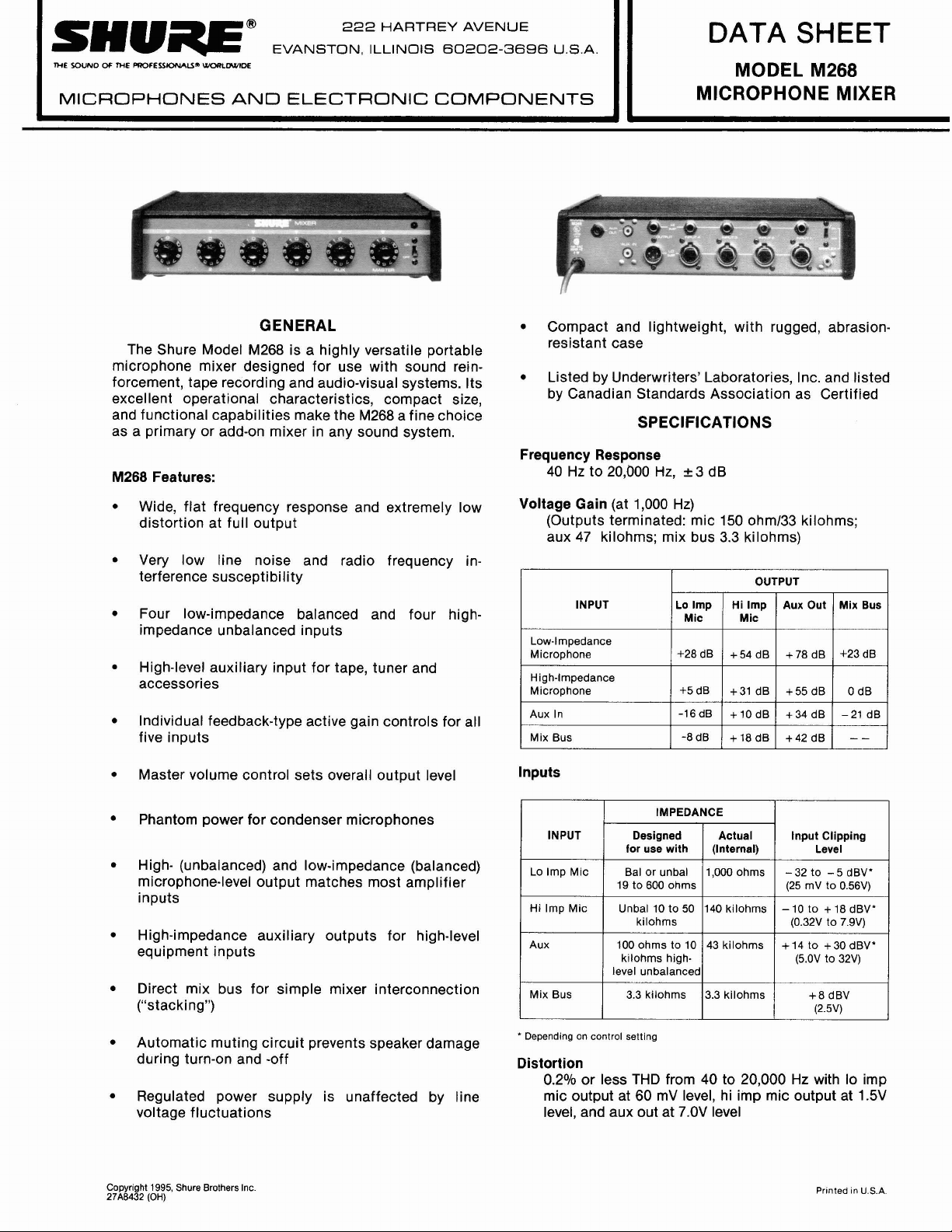
Outputs
OUTPUT
Low Imp
Mic
High Imp
Mic
Aux
Mix Bus
IMPEDANCE
Designed for
Use W
ith
Any low imp
(19 to 600
mic circuit
Unbal 10 to
50 k
10 k
greater
unbalanced
high-level cir-
mic
circuit
cuits
3.3 k
)
or
Actual
(Internal)
120
5 k
2.5 k
3.3 k
Output
Clipping Level
–22 dB
(10
0 m
V)
+4.5 dBV
(1.7 V)
18 dBV
(7.9 V)
–8 dBV
(0.4 V)
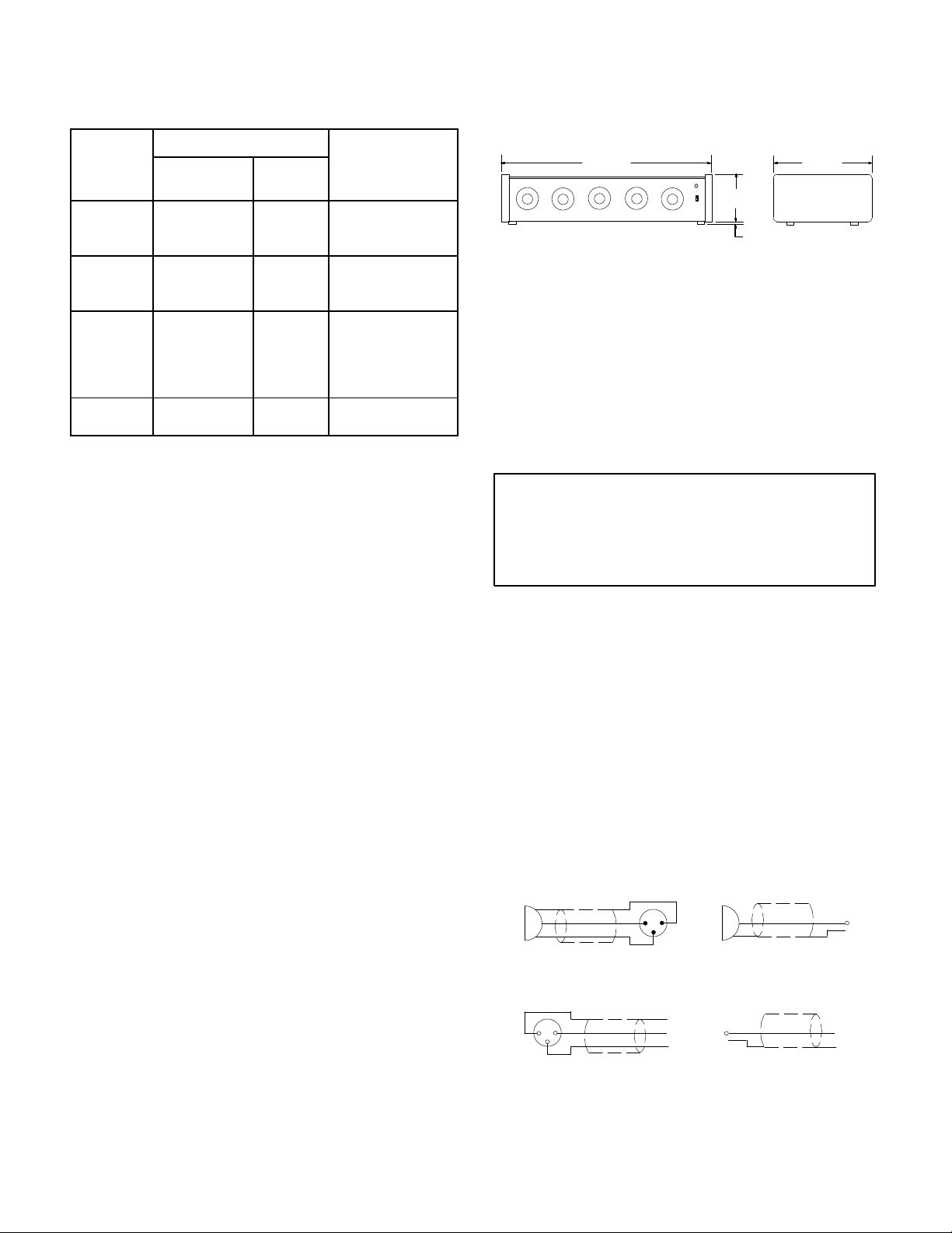
Dimensions
See Figure 1.
309
mm
(12 5/32 in.)
68.8mm
(2 23/
in.)
32
6.3
(1/4 in. )
mm
229 mm
(9 in.)
FIGURE 1
Weight
Net: 1.8
Packaged:
kg (4 lb 1 oz)
2.8 kg (6 lb 1 oz)
Certifications
Listed by Underwriters’ Laboratories, Inc., and listed
Canadian Standards Association as Certified
by
Noise
Equivalent
mic
150 - 300-20,000 Hz) at full gain
Input Noise:
–128
dBV (low impedance
Equivalent Input Hum and Noise: –125 dBV (low
impedance
mic 150 - 20-20,000 Hz) at full gain
Output Noise: –90 dBV (master control down). –65
(
maste
r up), (
inpu
t c
ontrol
s d
own
, 3
own
maste
, 2
00-20,00
r d
0-20,00
dBV
Output
Hum and N
oise
dBV (master up) (inpu
: –82 dBV (
t c
ontrol
s d
Common Mode Rejection
65 dB minimum with 100 mV input at 100 Hz
Control Interaction
Less than 1 dB with any control combination
Phase
All microphone inputs and outputs in phase; tips of
high-impedance
pin
3; aux input in phase with aux outputs and pin 2
inputs
and mix bus jack in phase with
Phantom Power
own)
0 H
0 H
, –
z)
60
CONTROLS AND CONNECT
ORS
WARNING
This
apparatus must be earthed (grounded)!
M268
power supply is energized when the unit
connected to an ac source; disconnect mains
(power)
z)
Inputs
A
m
ribbon
plug from supply when not in use.
aximu
m o
f four low- and four h
o
r c
ondense
r m
icrophone
s can b
igh-impedanc
e c
onnecte
tacles marked INPUT 1, INPUT 2, INPUT 3, and INPUT 4.
The
i
nput
s are d
esigne
d for l
ow-impedanc
e m
19 to 600 impedance, or high-impedance microphones.
Both
low- and h
multaneously .
igh-impedance microphone
Crysta
l o
r c
erami
c m
icrophone
s can b
mended. The input receptacles are professional three-pin
XLR
A
udio-typ
e c
onnectors
, and 1/
p
hon
4
e j
ure 2 for low- and high-impedance connections to inputs.
Note that some condenser microphones produce very high
output
s
ignal
s w
hic
h may o
verloa
d the i
nput
s o
the M268’s feedback-type active gain controls virtually elimi nate th
e n
eed fo
r i
n-lin
e a
ttenuator
s t
o c
ompensat
“hot” microphones.
SHIELD
2
1
3
The
e d
d t
icrophone
e used s
s are not r
acks
. See F
f many m
e for t
SHIELD
is
ynamic,
o r
eceps w
ecom-
ixers;
hese
ith
i-
ig-
30 Vdc open circuit, 3.3 k series resistance
Operating V
120
for
oltage
or 240 volts ±10%, 50/60 Hz, 5W
120 V
ac operation (see Service section
operation)
Temperature
Range
Operating: –18o to 57o C (0o to 135o F)
Storage: –29o to 74oC (–20o to 165o F)
, supplied wired
for 240 V
ac
LOW IMPEDANCE OUTPUT
2
MICROPHONE
1
2
3
(BALANCED LINE)
MIXER
LOW IMPEDANCE
(BALANCED LINE)
MICROPHONE OUTPUT PLUG CONNECTIONS
INPUT
MICROPHONE INPUT CONNECTIONS
SHIELD
HIGH IMPEDANCE OUTPUT
FIGURE 2
MICROPHONE
HIGH IMPEDANCE
MIXER INPUT
SHIELD
Page 3

The rear-panel phone jack marked AUX IN will accept
from a high-impedance, high-level source such as
output
a tape recorder or am-fm tuner.
Outputs
connectors
The
marked LOW IMP OUTPUT and HI IMP
OUTPUT are the “mixed” output of all the input sources
and
are designed to work into a balanced (low impedance
only)
or unbalanced 150- to 600- microphone line or into
a high-impedance unbalanced amplifier or tape recorder
microphone input. The output connectors are a professional three-pin XLR audio connector and a
jack.
See Figure 2 for output connector configurations.
The
phone and phono jacks marked AUX OUT are highimpedance,
marily
high-level, unbalanced outputs designed pri
to feed a power amplifier requiring 0.1 to 2 volts in
1
/4I phone
put, or the auxiliary or tuner input of an amplifier or tape
recorder. Interconnecting cables should be limited to a
maximum
length of about 25m (75 ft).
Controls
In
a
dditio
n t
o the p
owe
r O
N/OF
F s
witc
h (an a
djacen
t L
ED
indicates
five
AUX,
put.
panel
p
ower-on in a
i
ndividua
and a M
l i
npu
ASTE
Note that the i
d
irectl
y b
ehin
c o
peration)
t gain c
ontrol
R gain c
npu
d t
ontrol fo
t c
onnectors ar
heir correspondin
s d
esignate
, the f
r the t
e l
ron
t p
ane
d 1 t
hroug
ota
l p
ocate
d o
g gain c
l c
ontains
h 4 a
rogra
n the r
ontrols.
m o
nd
ut-
ear
The M268 has feedback-type active gain controls for
lower
noise and greater dynamic range. In general, the in
dividual gain control should be set to 5 or higher (clockwise),
and
the MASTER control adjusted for the required
output.
If overload
high-level
sources, reduce the individual gain control set
distortion (clipping) occurs when using
tings. Unused individual gain controls should be kept at
the
minimum setting (counterclockwise).
Mix Bus
The rea
r p
ane
l MIX BUS p
hon
o jack f
acilitate
s the “
stacking” of mixers to obtain additional inputs without using any
of th
e M268 i
for
i
nstance
ing
two i
amplifiers
gain
will b
adversely
nections
the M26
nputs
. C
, d
irectl
ndependen
with 1
0 i
ndividuall
e r
educe
a
ffecte
d b
can also b
7 and the M
onnectin
y c
onnect
s t
t m
aste
r c
ontrol
y c
d b
y 6 dB, but n
y this i
nterconnection
e made with o
67.
g the mix b
hei
r m
ixin
s and two i
ontrolle
ois
the
d i
e s
r S
uses of two M
g s
ystems
solate
, p
d o
268s,
rovid-
nputs. Note that t
pecification
. Mix bus i
hur
e m
ixer
s are n
ntercon-
s such a
utput
he
ot
Phantom Power
The
M268 provides power for condenser microphones
such as the Shure SM81 and SM85. The rear-panel
PHANTOM OFF/ON switch controls the application of
phantom voltage to all low-impedance inputs. With the
PHANTOM
switch on, +30 Vdc is applied to pins 2 and 3
of each LO IMP connector. Series current-limiting resistance
is 3.3 k for each input. When using other condens
er
microphones with the M268, verify that the voltage and
resistance
are compatible.
Balanced low-impedance microphones (dynamic, rib-
bon,
self-powered condensers) can be used in combina
tion with phantom-powered condenser microphones.
IMPORTANT: Do not turn on the PHANT
OM switch
using unbalanced low-impedance microphones: objec-
tionable hum will result. Turn off the PHANTOM switch
condenser microphones are not being used.
when
Use only high-quality cable, as intermittent shorts between broken shied wires and balanced conductors will
cause
of
fensive noise transients in the system.
ACCESSORIES
Model A268R
The
x 89 mm (19 in. x 31/2 in.) precut rack panel and
-
hardware for rack mounting the M268 in a standard 483
-
mm
(19 in.) rack panel.
Rack Panel Kit consists of a 483 mm
The Model RKC169 Rack Panel Bracket Kit enables
users of the Shure A68R Rack Panel Kit (originally designed
the
for the Shure M67 and M68 Mixers) to rack-mount
M268 with the A68R.
SERVICE
WARNING
V
oltages in this equipment are hazardous.
Refer servicing to qualified service personnel.
Operation at 210-250 V
The M268 is supplied wired for operation at 105-125
T
o rewire the M268 for operation at 210-250 V
Vac.
ceed
-
as follows:
1. Disconnect the M268 from the ac line
2. Remove end caps and cover
3. Locate
Power Transformer T106 at right center of
printed circuit board. Remove two jumpers between
holes
marked “120V ONLY.” Add jumper between
marked
4. Replace
Vac
“230V ONL
ac connector with one designed for 210-250
source. If
M268 is to be used outside U.S. and Can
ada, local regulations may require replacing line cord
with
one having wire insulation colors as follows:
s
U.S., Canada
Europe Brown Blue Green/
5.
R
eplace Fus
e F101 (
0.05A, 250V, time lag unit (Shure 80C380, Schurter
034.3104) using supplied fuse clips (Shure 80A8008,
O
G 7
-
Schurter
6. Replace
panel
to reflect new operating voltage range.
51.0052).
cover and end caps. Affix new label to rear
ac
.
Y” at right of T206.
“Live” or
Neutral
“Hot”
Black White Green
presentl
y 0
.1A
, 2
50V
, s
necessary
ac, pro
Earth or
Ground
Yellow
low-blow
when
holes
) w
ith
-
-
-
3
Page 4

Page 5

Page 6

 Loading...