

Page 1
GENERAL
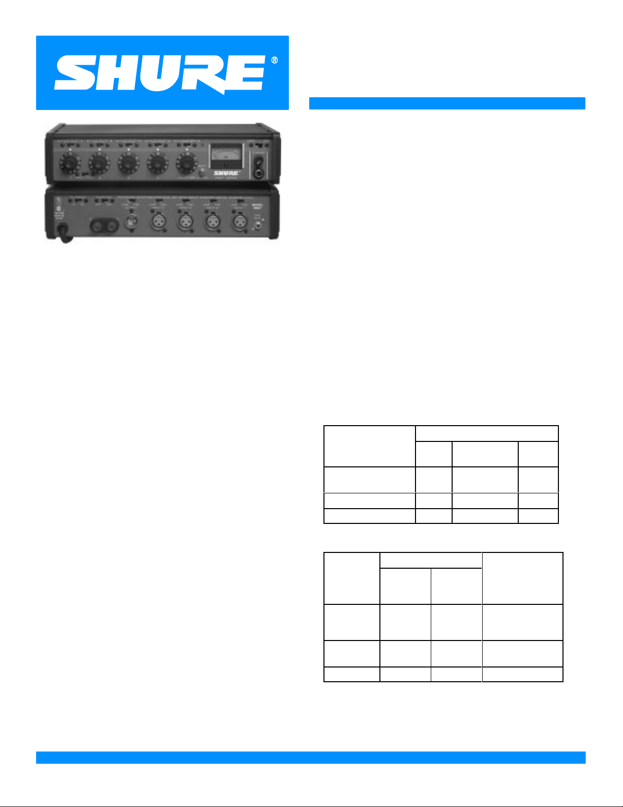
The Shure Model M267 is a microphone mixer-remote
amplifier specifically designed for professional applications.
The excellent performance, versatility and features of this
complete, compact console make it an ideal choice for studio, remote, or sound reinforcement use, and as an add-on
mixer for expanding existing facilities. It is also ideally suited
for use with audio and video tape recorders to provide multiple microphone inputs.
Features:
S Wide, flat frequency response and extremely low dis-
tortion up to +18 dBm output
S Extremely low noise and RF susceptibility
Four switchable microphone- or line-level balanced-line
S
inputs with individual gain controls and low-frequency
rolloff switches. MUMETAL shielding on input transformers
S Feedback-type input gain controls for maximum clip-
ping levels and dynamic range
S Output switchable for line or microphone level
S Built-in switchable peak limiter cuts output overload
distortion, adapts to power supply voltage
S LED indicator shows limiter operation or overload with
limiter defeated
S Externally adjustable limiter threshold (–4 to +18 dBm)
S VU meter calibrated for +4 and +8 dBm with range
switch. Illuminated with ac operation
S Ac or built-in battery operation. Noiseless automatic
switchover to battery in case of ac line failure. Battery
test without program interruption
S Front-panel headphone level control and monitor jack
drives almost any stereo or mono headphones; output
can be additional unbalanced line feed to drive a tape
recorder or power amplifier
Shure Brothers Incorporated
222 Hartrey Avenue
Evanston IL 60202-3696 U.S.A.
Model M267 User Guide
S Direct mix bus for stacking units
S Automatic muting prevents speaker damage during
turn-on and -off
S Low distortion, high-stability tone oscillator for line test
and level checks
S All connections phased. Line output terminals phase-
indicated
S Compact and lightweight, with rugged, abrasion-resis-
tant case
S Internally selectable 120 or 240 V ac, 50/60 Hz opera-
tion
S Underwriters’ Laboratories Listed and Canadian Stan-
dards Association listed as Certified
SPECIFICATIONS
Frequency Response
30 Hz to 20,000 Hz, ±2 dB
Voltage Gain (at 1,000 Hz)
(Outputs terminated: line 600 W, microphone 150 W, mix
bus 3.3 kW, headphone 200
sleeve )
Input
Low-Impedance
Microphone (150
Line 40 dB –9 dB –27 dB
Mix Bus 55 dB 5 dB – –
Line Microphone Mix
91 dB 41 dB 24 dB
Ω)
Inputs
IMPEDANCE
Designed
Input
Microphone 19 to
Line Less
Mix Bus
∗Depending on input control setting
for Use
With
600 Ω
than10 kΩ
3.5 kΩ 3.5 kΩ
(Internal)
W, tip-sleeve and ring-
OUTPUT
Actual
1 kΩ
66 kΩ
Input
Clipping Level
–32 dBV to
–5 dBV∗
(25 mV to 0.56 V)
+20 dBV
+7 dBV (2.2 V)
Bus
E1999, Shure Brothers Incorporated
27A8376 (SE)
Printed in U.S.A.
Page 2
Outputs
Headphone Output Clipping Level
IMPEDANCE
Designed for
Output
Microphone Any low imped-
Mix Bus
Headphones
Line
∗∗Depending on level control setting
Use With
ance microphone
input
3.5 kΩ 3.5 kΩ
8 - 2000 Ω
200 Ω
recommended
600Ω 150Ω
Actual
(Internal)
0.5 –34 dB
400 Ω to
3 kΩ∗∗
Clipping Level
(400 mV)
+18 dBm
Output
(2 0 mV)
–8 dBV
+10 dBV
(3.3 V)
(6.2 V)
Noise
Equivalent Input Hum and Noise: –126 dBV (low im-
pedance microphone, 150 Ω - 20-20,000 Hz) into a
600 Ω load at full gain
Output Noise: –75 dBV (master control fully counter clockwise), –53 dBV (master fully clockwise), (input controls down, 300-20,000 Hz)
Output Hum and Noise: –70 dBV (master control
down), –51 dBV (master control up) (input controls
down, 20-20,000 Hz)
3.16V (+10 dBV) into 200 Ω
Tone Oscillator
1,000 Hz, 1.5% or less THD
Phantom Power
30 Vdc open-circuit, 3.3 kΩ series resistance, input
switches in MIC position only
Operating Voltage
Ac Operation: 120 or 240 volts ±10%, 50/60 Hz,
9.5W, internally switchable[
Dc Operation: 27 volts nominal at 15 mA typical no-
signal, 18 mA typical at 0 VU (+4 dBm) output with
headphone load; 21.5 volts minimum
Battery life: approximately 20 hours with alkaline batteries at +4 dBm output in continuous use; three 9-volt
batteries, type NEDA 1604A (Duracell MN1604 recommended)
[ Supplied wired for 120 V ac operation (See Service section for 240
Vac operation)
Distortion
0.35% or less THD from 30 to 20,000 Hz at +15 dBm
output; 0.5% or less IM distortion up to +15 dBm output
level
Common Mode Rejection
65 dB minimum with input of –20 dBV at 100 Hz
Control Interaction
Less than 1 dB with any control combination
Overload and Shorting Protection
Shorting the outputs, even for prolonged periods, will
cause no damage; microphone inputs will not be damaged by signals up to 3 volts
Lo-Cut Filters
6 dB/octave rolloff at 150 Hz
Limiter
Threshold: +15 dBm (line output level; adjustable
from –4 to +18 dBm)
Attack Time: 3 msec typical
Recovery Time:500 msec typical
Temperature Range
Operating: –18o to 57o C (0o to 135o F)
o
Storage: –29
to 71oC (–20o to 160o F)
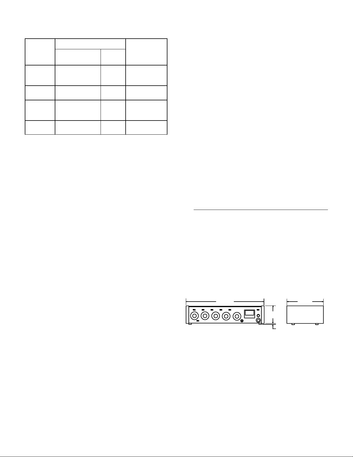
Dimensions
See Figure 1
309 mm
(12 5/
in.)
32
(2 23/32 in.)
FIGURE 1
Weight
Net: 2.3 kg (5 lb 2 oz)
Packaged: 3.2 kg (7 lb 2 oz)
Certifications
68.8mm
6.3 mm
(
1
/4 in. )
229 mm
(9 in.)
Peak Indicator
Lights 6 dB below clipping or at onset of limiter action
Listed by Underwriters’ Laboratories, Inc., and listed by
Canadian Standards Association as Certified
2
Page 3
CONTROLS AND CONNECTORS
WARNING
This apparatus must be earthed (grounded)! The
M267 power supply is energized when the unit is
connected to an ac source; disconnect mains
(power) plug from supply when not in use.
Input control 1 serves an additional function as the level
control for the tone oscillator when the INPUT 1/OCS 1
switch is in the OSC 1 position.
IMPORT ANT: For optimum signal-to-noise ratio, the individual input controls should be operated at as high a setting as possible, consistent with maintaining adequate
control range and input clipping level.
Master Gain Control
Inputs
The four inputs are professional three-pin female XLR
audio connectors located on the rear panel and designated
INPUT 1 through INPUT 4. The inputs are balanced (internal transformer, MUMETAL shielded); pins 2 and 3 are
“hot”, and pin 1 is “ground”. For microphone operation, the
switches labeled LINE/MIC (directly above the input connectors) must be in the MIC position; for line level inputs,
the switches must be in the LINE position. For impedance,
clipping and operating signal levels, refer to the SPECIFICATIONS section.
Outputs
The rear-panel connector labeled OUTPUT is a professional three-pin male XLR audio connector. With the adjacent LINE/MIC switch in the MIC position, the OUTPUT
connector is used to feed a low-impedance microphone
line or a low-impedance microphone input. With the LINE/
MIC switch in the LINE position, the OUTPUT connector
feeds the line-level input of an amplifier, tape recorder, or
another mixer. The OUTPUT connector is a balanced output with the LINE/MIC switch in either position; pin 1 is
ground, pins 2 and 3 are “hot”, and the connector is in
phase with the corresponding pins of the input connectors.
The rear-panel binding-post connector designated LINE
OUTPUT is in parallel with the OUTPUT connector and
can be used as a line-level output feed simultaneously with
the OUTPUT connector. The terminals are numbered 2
and 3 and are in phase with the corresponding pins of the
input connectors. While the line outputs can be used to
drive various impedance lines, the VU meter is calibrated
for use with a 600 Ω line.
The line output transformer will operate properly with up
to 100 mA dc in the line. This feature permits the use of
standard “dialed-up” telephone lines with dc across them.
(Since a slight distortion increase may occur at high output
levels with maximum dc current, operation with the VU
RANGE switch at +4 dBm is recommended.)
Input Gain Controls
The front-panel control designated MASTER is the master gain control which sets the overall output level of the
mixed sources (including signals applied to the MIX BUS
input).
Limiter
The front-panel LIMITER IN/OUT switch turns on a fastacting, peak-responding limiter circuit that cuts overload
distortion during loud program intervals without affecting
normal program levels. When the LIMITER switch is IN
(operating), the mixer output is limited to approximately
+15dBm. Increasing the individual or MASTER gain controls will increase the average output and the amount of
limiting. The limiter threshold can be reset to any other output between –4 and +18 dBm if desired. With the limiter
switched OUT and tone oscillator activated, adjust INPUT
1 and MASTER level controls to produce an output 0.5 dB
higher than desired. Switch the limiter IN and set the LIMITER THRESHOLD ADJUST control (accessible though
the bottom of the chassis) for the desired level.
The front-panel PEAK LED indicator shows limiter operation with the limiter in, and operates when program levels approach overload with the limiter out. The indicator is
much faster than a meter and will be activated by the shortest transient peak, but it remains on long enough to provide
easy recognition.
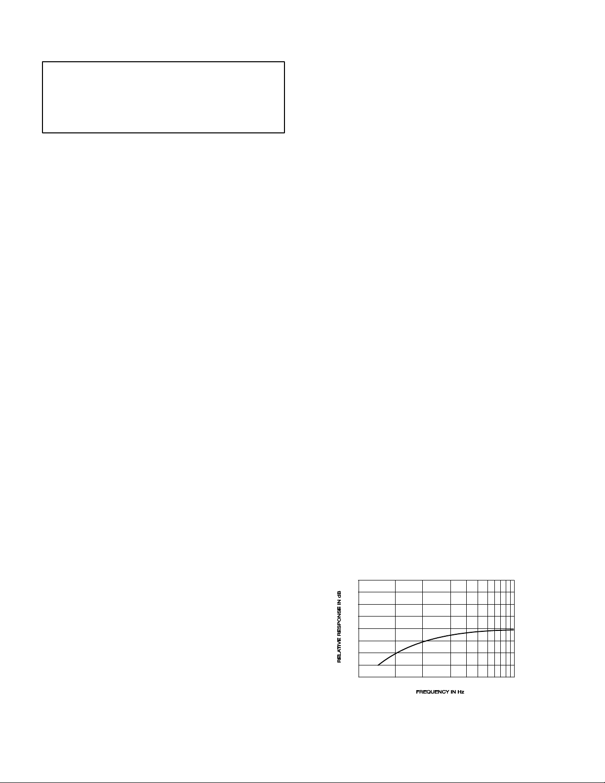
Low-Cut Filters
The low-cut filters provide a low-frequency rolloff to the
response curve as shown in Figure 2. The filters are activated by the LO-CUT IN/OUT switch above each individual
input gain control and can be used individually with each
control to reduce wind noise or undesirable low-frequency
signals such as from condenser microphones or turntable
rumble.
0
The front-panel controls designated 1 through 4 are the individual active gain controls for correspondingly numbered
inputs. Note that the input connectors are located on the rear
panel directly behind their corresponding gain control. The
controls set the preamplifier gain and provide preamplifier
output attenuation. As the gain is reduced, the preamplifier
input clipping level is increased for that channel.
–10
–20
20
100
200
500
1,00050
LOW-CUT FILTER ACTION
FIGURE 2
3
Page 4

Mix Bus
Phantom Power
Direct access to the mixing bus is provided through the
rear-panel MIX BUS phono pin jack. This provision is made
primarily to facilitate stacking or “multing” M267s to
achieve additional input capacity without losing any inputs.
With two M267s, for example, the two mixing buses are directly connected, providing two independent master gain
controls and two isolated line amplifiers with eight individually controlled inputs. Since the buses are directly paralleled, a 6 dB drop in gain will occur; and the master or input
controls must be increased to compensate. Noise specifications are not adversely affected by this interconnection.
Mix bus interconnection can also be made with other
Shure mixers, such as the M268, FP42. etc.
VU Meter
The VU meter is factory-calibrated for use with a 600 Ω
terminated line. The VU RANGE switch on the rear panel
selects either a +4 or +8 dBm output at 0 VU meter indication. (This switch changes the meter indication but does
not change the actual output level.) Microphone output
levels are 50 dB below line output. The +4 range is recommended for normal use to provide approximately 14 dB of
headroom from operating level to clipping level.
The VU meter is illuminated by two No. 86 lamps operating well under their normal ratings for a life expectancy of
greater than 10,000 hours. The lamps are only lit during
ac operation. Consequently, the illumination serves as a
visual alarm if the ac is interrupted and the unit has
switched to battery.
The VU meter is connected on the primary side of the
output transformer to assure protection from any dc level
on a telephone line.
Headphones
The headphone outlet appears at the front-panel jack
panel designated PHONES. The two-circuit phone jack
will accommodate most stereo or mono headphones. The
output level is sufficient to provide high volume for use in
noisy environments.
Note that the headphone output level is also high
enough to use as an auxiliary unbalanced line feed to drive
a tape deck or a power amplifier.
The tip and ring connections of the headphone plugs are
in phase with pin 3 of all input and output connectors, and
with the tip of the MIX BUS jack.
Tone Oscillator
The highly stable, low-distortion tone oscillator provides
for line test and level checks. The oscillator is instantly activated by the front-panel INPUT 1/OSC 1 switch; its level
can then be controlled by the INPUT 1 gain control on the
front panel. The tone oscillator frequency is 1,000 Hz, and
the signal appears on both the line and microphone outputs, as well as the headphone and mix bus connectors.
The oscillator should be switched off (INPUT 1 position)
when not in use.
The rear-panel PHANTOM OFF/ON switch controls the
application of phantom power for condenser microphones,
such as the Shure SM81 and SM87A, to all inputs. With
the switch on and the rear-panel MIC/LINE switches in the
MIC positions, +30 Vdc is applied to pins 2 and 3 of each
input connection. Series current-limiting resistance is 3.3
kΩ for each input. When using other condenser microphones with the M267, verify that the voltage and resistance requirements are compatible.
Note that the phantom power cannot normally be applied to the inputs with the MIC/LINE switches in the LINE
position.
IMPORT ANT: Do
using
unbalanced
tionable hum will result. Turn off the PHANTOM switch
when condenser microphones are not being used.
Use only high-quality cable. Intermittent shorts between
broken shield wires and balanced conductors will cause offensive noise transients in the system.
BA TTERY OPERATION AND EXTERNAL POWERING
In addition to ac operation, the M267 can be operated
from an internal battery pack. Current drain is typically 17
mA at +8 dBm output level and typically 15 mA at + 4 dBm.
Battery power is recommended both for remote, on-location operation, and as an emergency backup source in
case of failure of the ac power.
Access to the battery compartment is provided at the
bottom of the chassis. Three 9-volt alkaline batteries power the M267 at full rated output. Use alkaline batteries for
maximum life. Duracell MN1604A or Eveready 522 are
recommended. Battery life is approximately 20 hours at +4
dBm continuos use. Note that battery operation with phantom power loads and high level headphone monitoring will
increase battery drain.
With batteries in the battery compartment, the M267 will
automatically and silently switch to battery operation
should the ac voltage fall below a suitable level. If the ac
power fails completely , the VU meter lamps will go out, providing a visual indication of line failure.
Battery condition can be determined by using the BA TT
CHECK switch on the front panel. Activate the BATT
CHECK switch and observe the VU meter. A new set of
batteries will give about a +2 VU indication. Battery condition is good if the reading is above 0 VU; a lower reading
means that new batteries are required for proper operation. Note that the M267 power switch must be turned on
to check battery condition.
Telephone Interconnection
When using the M267 connected directly to a telephone
line, check to see whether the local telephone company requires an interface coupler between the M267 and the telephone line. If a coupler is required, make certain the coupler selected and the wiring arrangement are in
compliance with the telephone company regulations.
not
turn the PHANTOM switch on when
low-impedance microphones; objec-
4
Page 5

Telephone Line Surge Protection
When using the M267 connected directly to a telephone
line subject to lightning-induced voltage surges, the following commercially available part can be installed across the
LINE OUT terminals to provide additional protection for
output circuit components:
Metal Oxide Varistor, General Electric Co., Type No.
V22ZA1
ACCESSORIES
A268R Rack Panel Kit. The Model A268R Rack Panel Kit
includes a 19 in. x 3-1/2 in. (483 mm x 89 mm) precut rack
panel and necessary hardware for rack-mounting the
M267 (with its cover in place and end caps removed) in a
standard 19 in. (483 mm) rack panel.
RKC169 Rack Panel Bracket Kit. The Model RKC169
Rack Panel Bracket Kit enables owners of the Shure A68R
Rack Panel Kit (originally designed for the M67 and M68
Mixers) to rack-mount the M267 with the A68R.
SERVICE
WARNING
Voltages in this equpment are harzardous!
Refer servicing to qualified service personnel.
240 Vac Operation
To change the M267 operating voltage from 120 Vac to
240 Vac, follow these steps:
1. Disconnect the M267 from the ac line.
2. Remove the end caps and cover.
3. Locate the voltage selector switch (S201) at the right
rear of the main printed circuit board (Figure 3). Move
SD201 to the 240V position (toward the front panel).
F201
WHT
120V
T206
S201
240V
BLK
F202
T50/250V
240 V WIRING
FIGURE 3
4. Remove fuse F201 (0.1A, 250V , time lag) and replace
it with the supplied fuse F202 (0.05A, 250V , time lag).
Note that the F202 fuse holder is at right angles to the
F201 fuse holder.
5. Replace the ac line cord (if necessary) with one designed for the 240 Vac source. If the M267 is to be
used outside the U.S. and Canada, local regulations
may require replacing the line cord with one having
wire insulation colors as follows:
“Live” or
“Hot” Neutral
U.S., Canada Black White Green
Europe Brown Blue Green/
6. Replace the cover and end caps, and mark the rear
panel to reflect the new operating voltage.
Earth or
Ground
Yellow
5
Page 6

PRINTED CIRUCIT BOARDS
COMPONENT SIDE
INPUT TRANSFORMERS T201-T204
6
Page 7

Page 8

REPLACEMENT P ARTS LIST
REFERENCE
DESIGNA TION
C101,C209,
C219, C227,
C232
C115 86L628 Capacitor, Electrolytic, 250 µF , 50V Sprague
C201, C204C205, C208
C210 86M630 Capacitor , Electrolytic, 10 µF, 25V Sprague TE 1204
C212-C213 86R630 Capacitor, Electrolytic, 68 µF, 25V Sprague
C215, C218 86L626 Capacitor, Electrolytic, 470 µF , 35V Sprague
C216, C222 86A630 Capacitor, Electrolytic, 5 µF , 35V Sprague TE1303
C221, C229 86N630 Capacitor, Electrolytic, 22 µF, 35V Mallory F226KM
C223 86S628 Capacitor, Electrolytic, 1 µF , 50V Sprague TVA1300
D209,
D21 1-D214,
D222-D223,
D226-D229
D210, D217,
D230-D235
D218-D221 86A405 Diode, Germanium, 30V RCA 1N48, 1N60
D301 86F422 Diode, Light-Emitting General Instrument
F201 80F159 Fuse, Slow–Blow , 3AG, 0.1A, 250V Littlefuse 313000 Se-
F202 80C380 Fuse, Time Lag, 0.05A, 250V Schurter 034.3104
J1 95C450 Jack, Phono Switchcraft 3511A
J2A, B 90T2600 Connectors, Binding Post None
J101-J104 95B801 1 Connector , 3-Pin Female XLR Switchcraft Y3FDPC
J105 95B8012 Connector , 3-Pin Male XLR Switchcraft Y3MPC
J301 90BJ2600 Phone Jack Switchcraft L-1128PC
L101-L1 13 80A365 Ferrite Bead Ring Panasonic
M1 RKC170
MP1-MP5 90A8028 Knob, MIC 1-4, MASTER None
MP6 90A8029 Knobs, PHONE None
MP7 90A8027 Cover, Battery None
MP8-MP9 65A8008 End Cap None
PART
NUMBER DESCRIPTION
86T628 Capacitor , Electrolytic, 5 µF, 25V Sprague TVA 1303
86V628 Capacitor, Electrolytic, 22 µF , 6.3V Sprague
86A415 Diode, Silicon, Computer, 75V TI 1N4148
86A404 Silicon Rectifier, 100V , 1/2A Motorola 1N4002
Meter, 190 µA None
(95A8214)
COMMERCIAL
ALTERNATE
501D227F063PR
501D226F016LL
501D686F025MN
503D477F035QE
MV5075C
ries
Exc-ELSA35
REFERENCE
DESIGNA TION
PL301-PL302 95A8010 Lamp, 6.3V , 0.2A Sylvania 86
Q201 86A350 Transistor, NPN Motorola 2N5210
Q202, Q204 86A334 Transistor , NPN Rohm TIS92
Q203, Q205 86A348 Transistor , PNP Motorola 2N5087
Q206 86A335 Transistor, PNP Rohm TIS93
Q207 86A8302 Transistor, PNP Motorola TIP30A
R250 46A8016 Potentiometer, 100k None
R302, R306,
R310, R314
R317 46C8000 Potentiometer, 200k None
R322 46D8000 Potentiometer, 5k None
S101-S104 55B8008 Switch, Slide, 3PDT None
S105, S302, S306 55B8007 Switch, Slide, DPDT None
S106-S107, S301,
S303-S305
S201 55A8035 Switch, Slide, DPDT Switchcraft EPS1-PC1
S307 90CB2600 Switch, Pushbutton, SPDT Switchcraft 953
S308 55A8009 Switch, Slide, 3PDT None
T201-T204 95B8165 Transformer, Input None
T205 51E235A Transformer, Output None
T206 51A8021 Transformer, Power None
U201 86B808A Integrated Circuit, Quad Op Ampl
U202 86A8908 Opto-Isolator None
U203 86A811A Int eg r a t e d Ci rc u it , Dual Op Ampl Raytheon RC4559NB
U204 86A806A Integrated Circuit, Quad Comparator Raytheon LM339DB
U205 86A811A Integrated Circuit, Dual Op Ampl Raytheon RC4559NB
U206 86A803 Integrated Circuit, Dual Op Ampl Motorola MC1458C-P1
U207 86B8930 Integrated Circuit, Voltage Regulator National Semiconductor
W1 90A8045 Line Cord, AC None
Parts listed as RKC Kits should be ordered by that kit number.
PART
NUMBER DESCRIPTION
46B8000 Potentiometer, 100k None
55B8001 Switch, Slide, DPDT None
(Selected for NF)
COMMERCIAL
ALTERNA TE
Raytheon RC4156N
LM317A T
9
 Loading...